

Page 1
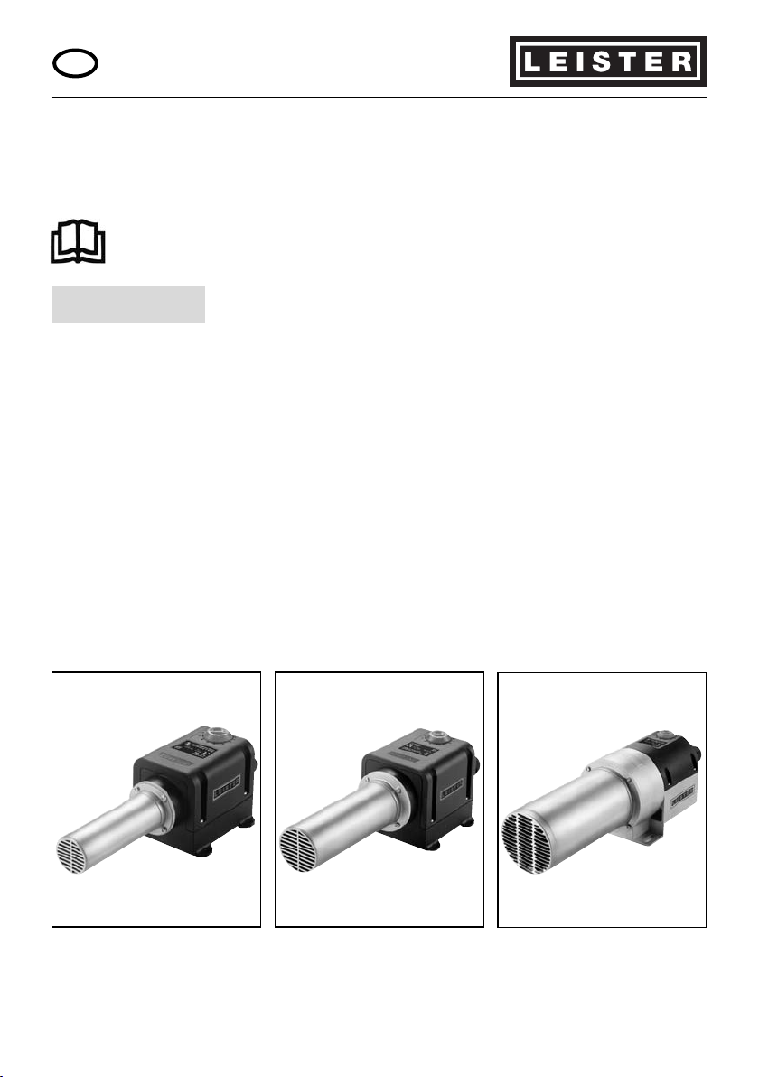
Leister LHS SYSTEM
Air Heater
Please read operating instructions carefully before use and
keep for further reference.
GB
OPERATING INSTRUCTIONS
The Leister Air Heater type LHS SYSTEM are suitable for building into machines,
installations or appliances and are designed for continuous operation.
• Drying and heating processes of various types.
• Shrinking and welding packaging films and moulded parts.
• Heating conveyor ovens or heat tunnels.
• Activating and loosening solvent free adhesives and melt adhesives.
• Sterilizing packaging materials such as bottles, corks and containers.
• Separating and fusing synthethic fibres and fabrics.
• Soldering processes on thin metal parts.
• Speeding up mixing processes and dissolving foams which can arise during
mixing and filling operations.
• Welding thermoplastic materials.
• Removing plastic mould flash.
• Putting a shine on plastic surfaces.
APPLICATION
Leister Process Technologies, Riedstrasse, CH-6060 Sarnen/Switzerland
Tel. +41 41 662 74 74 Fax +41 41 662 74 16
www.leister.com [email protected]
LHS SYSTEM 20S
LHS SYSTEM 20L
LHS SYSTEM 40S
LHS SYSTEM 40L
LHS SYSTEM 60S
LHS SYSTEM 60L
®
Page 2
Technical Data
LHS SYSTEM 20S 20L 40S 40L 60S 60L
Voltage V~ 100 – 230 200 – 230 100 – 230 3×230 – 3×440 3×230 – 3×480 3×230 – 3×480
Frequency Hz 50/60 50/60 50/60 50/60 50/60 50/60
Power
consumption kW 1.0 / 2.0 3.3 2.0 / 4.0 2.0 / 4.0 4.0 / 6.0 5.0 – 16.0
Air flow l/min. min. 100 min. 200 min. 200 min. 200 min. 300 min. 400
Temperature °C max. 650 max. 650 max. 650 max. 650 max. 650 max. 650
Ambient °C
temperature <65 <65 < 65 <65 <65 <65
Weight kg 0.55 0.65 0.85 0.95 3.15 3.65
Size mm 237×97×92 267×97×92 246×112×103 276×112×103 379×116×137 379 ×116×137
Mark of conformity ¬¬¬¬¬¬
Marl of approval ††††††
Certification scheme CCA CCA CCA CCA CCA CCA
Protection class I ‡‡
Protection class II ¶¶¶ ¶
2
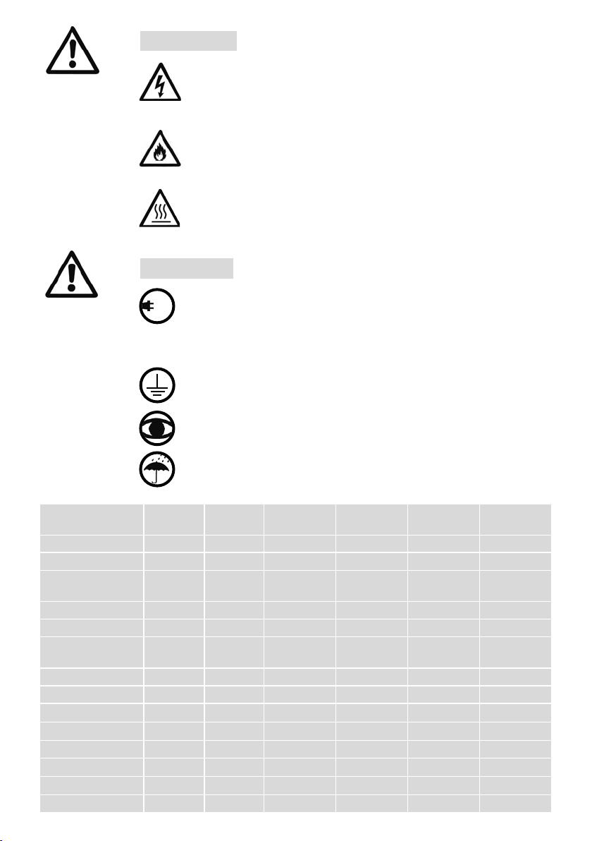
Danger! When opening up the tool, live components and
connections are exposed. The mains plug must be removed
from the main socket before opening up the tool. Caution
separate source voltage.
Incorrect installation and use of air heaters can present
a fire and explosion hazard, particularly in the proximity of
flammable materials and explosive gases.
Do not touch the element housing and nozzle when hot
as they can cause burns. Do not point the hot air flow at
people or animals.
WARNING
The tool must be operated with supervision. Warmth can
reach combustible materials, which are out of sight.
The voltage rating stated on the tool should correspond
to the mains voltage.
IEC/EN 61000-3-11; Z
max
= 0.047
Ω
+ j 0.029Ω. If necessary,
consultate supply authority.
Protect the tool from dampness and wet.
100
480
CAUTION
The tool with protection class I should be earthed using a
protective conductor.
Page 3

OPERATING Leister LHS SYSTEM
3
Installation
• When installing the tool, ensure that:
- only cold air is supplied
- no (hot air) back pressure develops
- the tool is not subjected to a hot air flow from another tool
• The tool is protected against mechanical vibration and shaking.
• Installation dimensions on pages 5, 6 and 7.
Air supply
• To protect the tool and the heat element, the stipulated minimum air flow must
under no circumstances fall short, and the maximum temperature (measured
at the hotest point 3 mm in front of the element housing) must also not be
exceeded. In the event that the minimum air flow falls short, the power must
immediately be disconnected.
• The air heater should only be supplied with air up to a max. 80°C.
• Pay attention to the direction of the airflow.
• Leister blowers must be used for the air supply (pay attention to the direction of
rotation and the electrical connection).
• For use in a dusty environment the tool should be fitted with a Leister stainless
steel filter on the air intake connection. Where a particularly critical dust problem
exists (eg metal, electrically charged or damp dust) special filters must be used to
avoid short circuiting of the tool.
Operation
• The tool must be connected by a qualified electrician in accordance with the
circuit diagram (Pages 5,6 or 7).
• Fit a nozzle appropriate to the use.
• It should be checked that the hot air can flow out freely, otherwise a back
pressure of hot air may damage the tool (danger of fire!).
• Attention: Keep to the minimum air flow according to the technical details
(Page 2).
• Switch on mains.
• Allow the tool to cool down after use.
Attention: Never operate tool without air supply!
Page 4
4
OPERATING Leister LHS SYSTEM
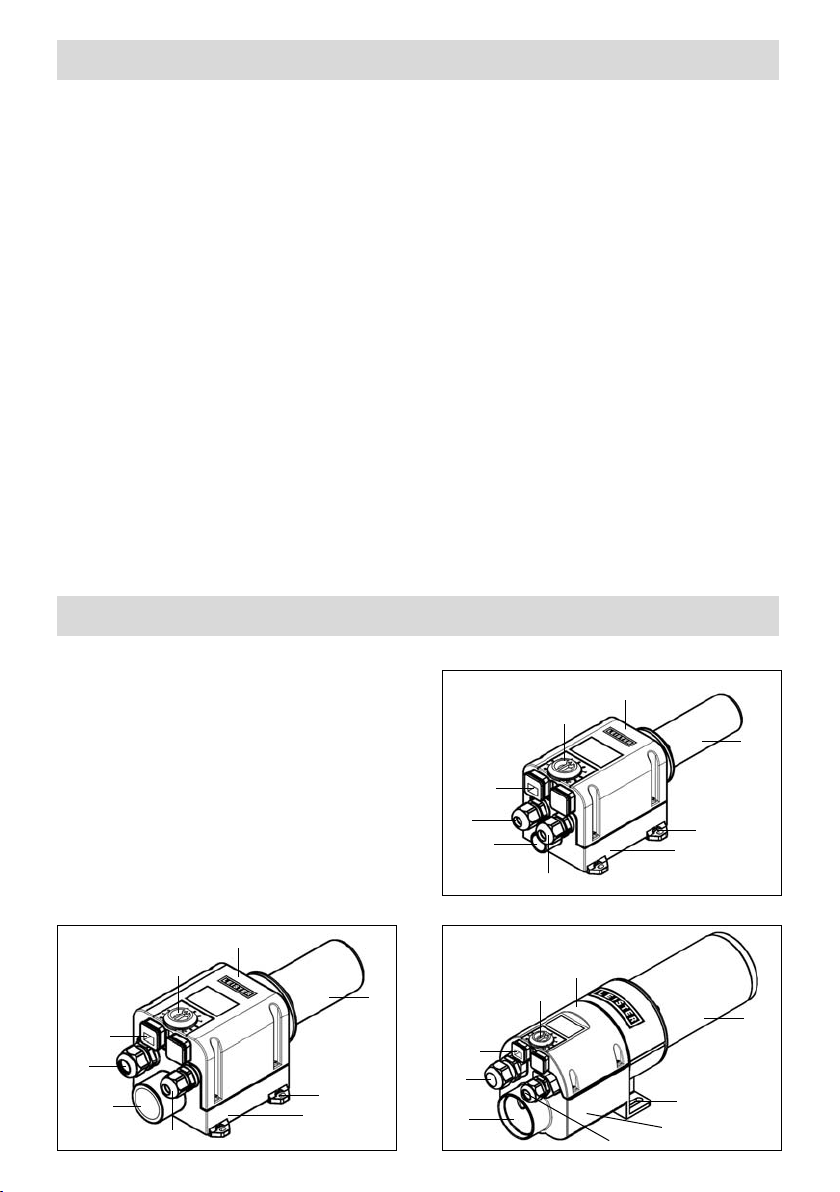
TOOL DESCRIPTION Leister LHS SYSTEM
Function: Heat element protection
If the heat element overheats, the power supply to the heat element is cut off and
the alarm relay function contact opens.
Function: Tool protection
If the tool overheats (air supply too warm or a build up of heat), the power supply for
the heat element is cut off and the alarm relay function contact opens.
Measures to be taken if the heating element or tool protection cuts out
• Check air supply.
• Check air volume.
• Check air flow.
• Re-connect tool to the mains.
6
5
2
1
1
4
7
8
3
5
2
1
4
5
2
1
4
3
LHS SYSTEM 20
LHS SYSTEM 40 LHS SYSTEM 60
1. Screw type cable fitting
2. Air intake connection
3. Power unit
4. Fitting plate
5. Element housing
6. Potentiometer for
temperature setting
7. Control unit
8. Control connection
1
1
3
6
6
7
8
7
8
Page 5
5
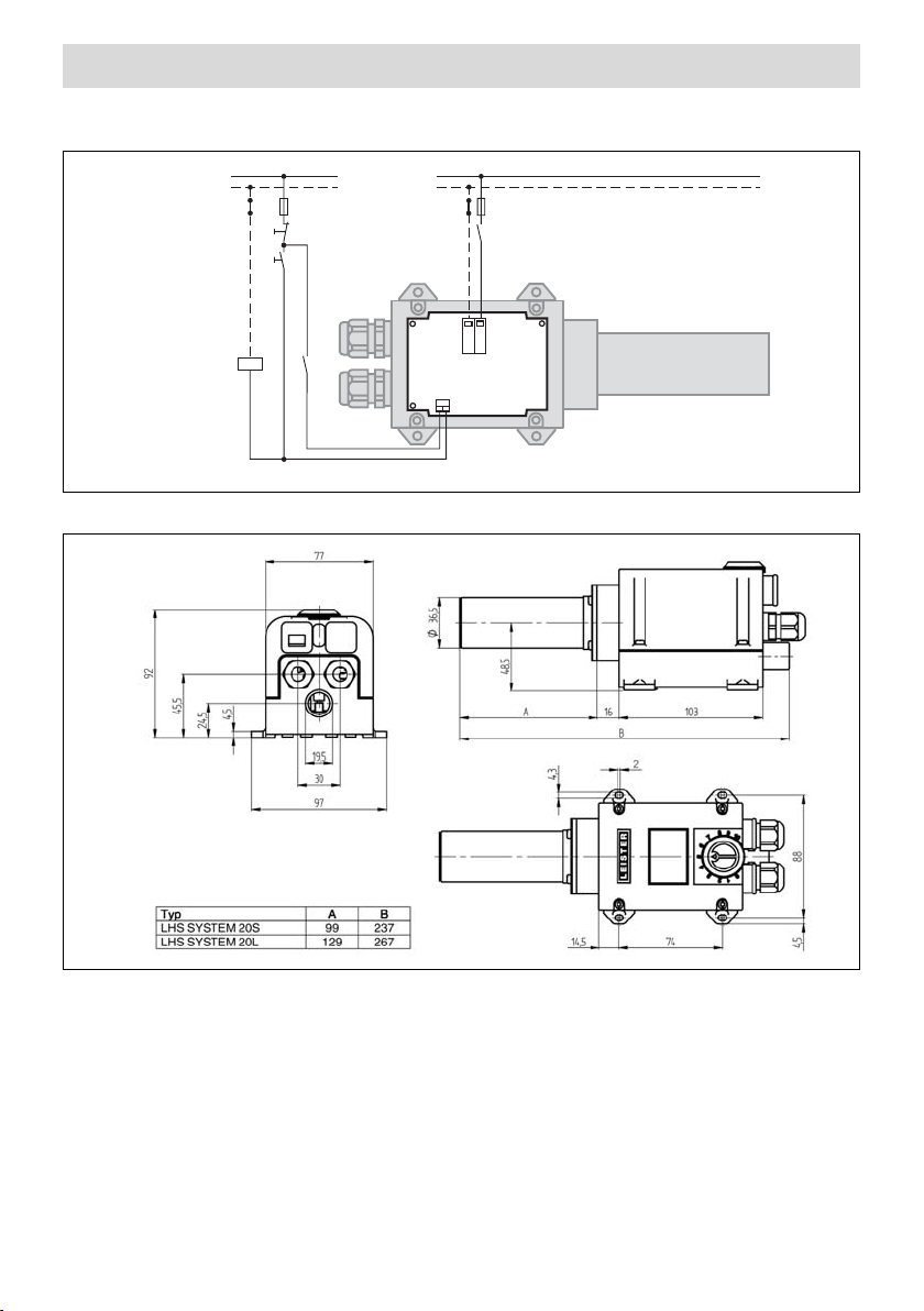
CONNECTION/INSTALLATION Leister LHS SYSTEM 20
Installation dimensions in mm
F2
Fuse
P
N
F1
Max 10A
L
N
N
L1
K1
K1
K1
S2
S1
OFF
ON
Power unit wiring diagram
20S/ 20L
Page 6
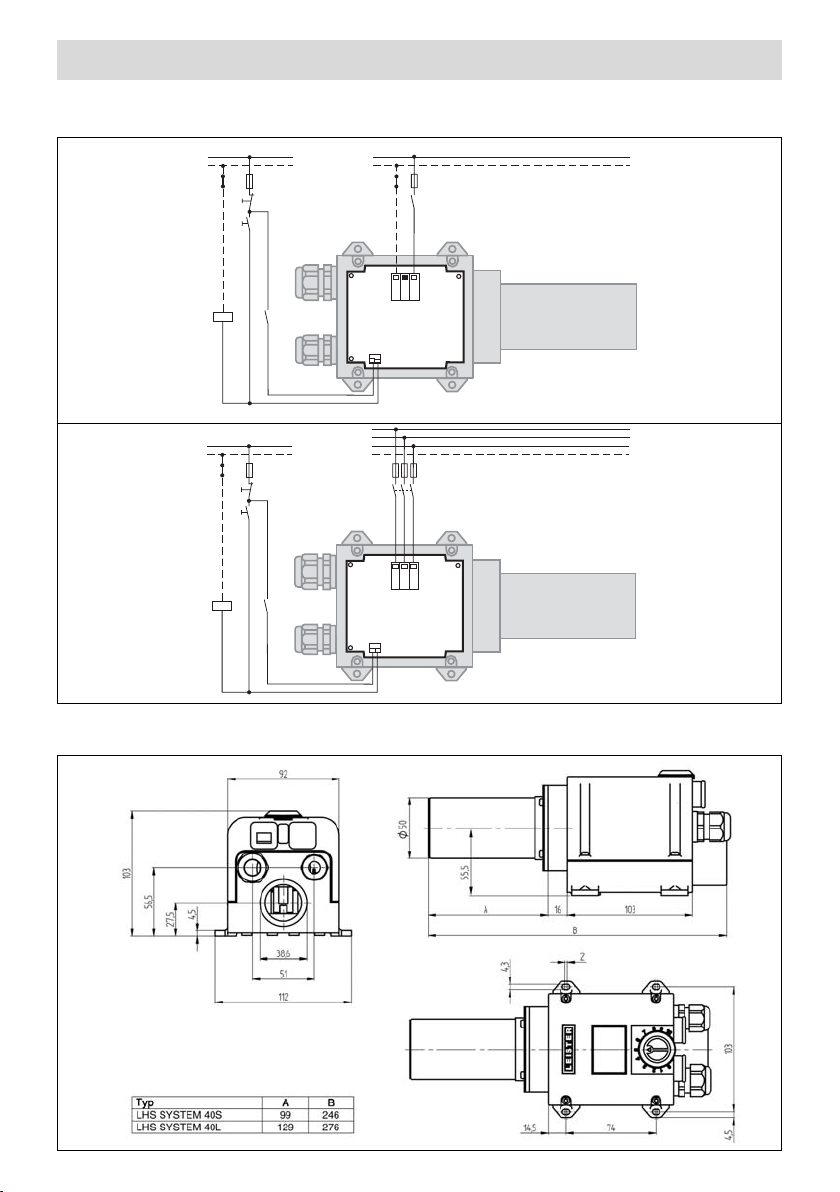
CONNECTION/INSTALLATION Leister LHS SYSTEM 40
6
Installation dimensions in mm
F2
Fuse
L1
N
K1
L3
L2
L1
L2
L3
P
N
F1
Max 10A
K1
K1
S2
S1
OFF
ON
N
L1
F2
Fuse
L
N
K1
P
N
F1
Max 10A
K1
K1
S2
S1
OFF
ON
Power unit wiring diagram
40S
40L
Page 7
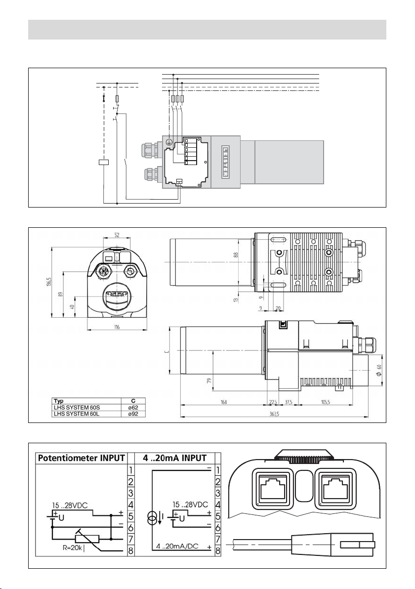
CONNECTION/INSTALLATION Leister LHS SYSTEM 60
7
Installation dimensions in mm
Power unit wiring diagram
60S / 60L
Control unit wiring diagram 20S / 20L, 40S / 40L, 60S / 60L
L3
P
N
F1
Max 10A
S1
OFF
S2
ON
K1
K1
F2
Fuse
K1
L1
L2
L3
L2
L1
N
PE
8
1
8
1
Page 8

BA LHS SYSTEM/ 05.2006/08.06
®
Leister Process Technologies, Riedstrasse, CH-6060 Sarnen/ Switzerland
Tel. +41 41 662 74 74 Fax +41 41 662 74 16
www.leister.com [email protected]
Leister Process Technologies and its authorised Service Centres offer free of charge
courses in the range of applications on page 1.
• Only Leister accessories should be used.
• Repairs should only be carried out by authorised Leister Service Centres. They
guarantee a correct and reliable repair service within 24 hours using original
spare parts in accordance with the circuit diagrams and spare parts lists.
• Guarantee and liability are in accordance with the guarantee certificate as well
as with the currently valid general business and sales conditions.
• Leister Process Technologies rejects any guarantee claims for tools which are not
in their original condition. The tools must never be altered or changed.
Technical data and specifications are subject to change without prior notice.
Your authorized Service Centre is:
GUARANTEE AND LIABILITY
SERVICE AND REPAIR
ACCESSORIES
TRAINING
 Loading...