

Leister HOTWIND PREMIUM, HOTWIND SYSTEM Operating Instructions Manual
HOTWIND
PREMIUM
HOTWIND
SYSTEM
Leister Technologies AG
Galileo-Strasse 10
CH-6056 Kaegiswil/Switzerland
Tel. +41 41 662 74 74
Fax +41 41 662 74 16
www.leister.com
sales@leister.com
®
GB I F
E P S TR
CZ CN J
D

GB
I
F
E
P
S
TR
CZ
CN
J
2
D
Size 3
Deutsch Bedienungsanleitung 4
English Operating Instructions 16
Italiano Istruzioni per l'uso 28
Français Notice d’utilisation 40
Español Instrucciones de funcionamiento 52
Português Manual de instruções 64
Svenska Bruksanvisning 76
Türkçe Kullanım Kılavuzu 88
Česky Návod k obsluze 100
ƅþ ƻǓƂ 112
日本語 取扱説明書 124
3
Type 800°C
Type 800°C
Type 800°C
Type 800°C
HOTWIND Size mm

Bedienungsanleitung
(Original-Bedienungsanleitung)
4
Heissluft-Gebläse
HOTWIND PREMIUM, HOTWIND SYSTEM
Die Heissluft-Gebläse HOTWIND PREMIUM und HOTWIND SYSTEM sind für den Dauerbetrieb ausgelegt.
Sie eignen sich hervorragend zum Einbau in Maschinen, Anlagen und Geräten oder auch als Handgeräte und
Tischgeräte.
Ihre wichtigsten Anwendungen sind zum Beispiel Trocknen und Aufheizen, Auftauen, Beschleunigen und
Auflösen, Sterilisieren, Glätten, Glänzen, Aktivieren und Lösen, Trennen und Verschmelzen, Schrumpfen,
Löten, Schweissen, Entfernen, Zünden.
Anwendung
D
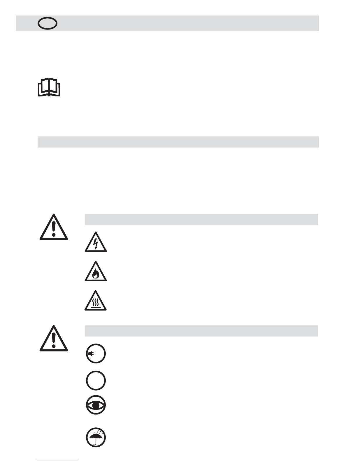
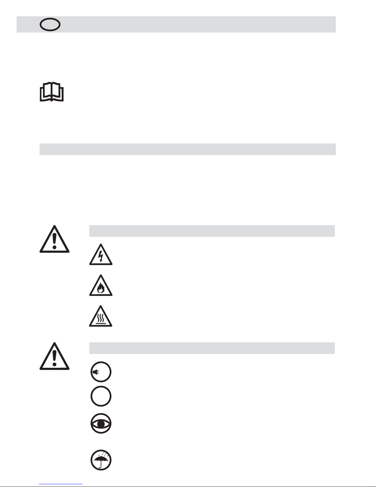
Bedienungsanleitung vor Inbetriebnahme aufmerksam
lesen und zur weiteren Verfügung aufbewahren.
Lebensgefahr beim Öffnen des Gerätes, da spannungsführende Komponenten und
Anschlüsse freigelegt werden. Vor dem Öffnen des Gerätes Netzstecker aus der
Steckdose ziehen.
Feuer- und Explosionsgefahr bei unsachgemässem Ge brauch von Heissluftgeräten, besonders in der Nähe von brennbaren Materialien und explosiven Gasen.
Verbrennungsgefahr! Heizelementrohr und Düse nicht in heissem Zustand
berühren. Gerät abkühlen lassen.
Heissluftstrahl nicht auf Personen oder Tiere richten.
Warnung
Gerät muss beobachtet betrieben werden. Wärme kann zu brennbaren Materialien
gelangen, die sich ausser Sichtweite befinden.
Gerät darf nur von ausgebildeten Fachleuten oder unter deren Aufsicht benützt
werden. Kindern ist die Benützung gänzlich untersagt.
FI-Schalter beim Einsatz des Gerätes auf Baustellen ist für den Personenschutz
dringend erforderlich.
Nennspannung, die auf dem Gerät angegeben ist, muss mit der Netzspannung
übereinstimmen. EN 61000-3-11; Z
max
= 0.053 + j 0.033 . Gegebenenfalls
Elektrizitäts-Versorgungs-Unternehmen konsultieren.
Gerät vor Feuchtigkeit und Nässe schützen.
FI
120
230
Vorsicht
Wir gratulieren Ihnen zum Kauf eines HOTWIND !
Sie haben sich für ein erstklassiges Heissluftgebläse aus dem Hause Leister entschieden, welches aus hochwertigen
Materialien besteht. Jeder HOTWIND wird einer strengen Qualitätskontrolle unterzogen bevor er das Werk in der
Schweiz verlässt.
5
(Im Sinne der EG-Maschinenrichtlinie 2006/42; Anhang II B)
Leister Technologies AG, Galileo-Strasse 10, CH-6056 Kaegiswil / Schweiz
erklärt hiermit, dass die
unvoll ständige Maschine
Bezeichnung: Heissluft-Gebläse
Typ: HOTWIND
Ausführung: PREMIUM oder SYSTEM
– soweit es vom Lieferumfang her möglich ist – den anwendbaren grundlegenden Anforderungen der EG-Maschinen richtlinie (2006/42) entspricht.
Die unvollständige Maschine entspricht überdies den Anforderungen der folgenden EG-Richtlinie(n):
EG-Richtlinie(n): Elektromagnetische Verträglichkeit
2004/108 (gültig bis 19.04.2016), 2014/30 (gültig ab 20.04.2016)
Niederspannungsrichtlinie
2006/95 (gültig bis 19.04.2016), 2014/35 (gültig ab 20.04.2016)
RoHS - Richtlinie 2011/65
Harmonisierte Normen: EN 12100, EN 55014-1, EN 55014-2, EN 61000-3-2, EN 61000-3-3,
EN 61000-3-11
(Z
max
)
, EN 62233, EN 60335-2-45, EN 50581
Ferner erklären wir, dass für diese unvollständige Maschine die speziellen technischen Unterlagen gemäss
Anhang VII (Teil B) erstellt wurden und verpflichten uns, diese auf begründetes Verlangen den Marktüberwachungsbehörden elektronisch zu übermitteln.
Name des Dokumentationsbevollmächtigten: Volker Pohl, Manager Product Conformity
Die Inbetriebnahme der unvollständigen Maschine wird so lange untersagt, bis gegebenenfalls festgestellt wurde,
dass die Maschine, in die die unvollständige Maschine eingebaut wurde, den Bestimmungen der EG-Maschinenrichtlinie (2006/42) entspricht.
Kaegiswil, 21.10.2015
Bruno von Wyl, CTO Andreas Kathriner, GM
Elektrowerkzeuge, Zubehör und Verpackungen sollen einer umweltgerechten Wiederverwertung zugeführt werden. Nur für EU-Länder: Werfen Sie Elektrowerkzeuge nicht in den Hausmüll! Gemäß der
Europäischen Richtlinie 2012/19/EU über Elektro- und Elektronik-Altgeräte und ihrer Um setzung in nationales Recht müssen nicht mehr gebrauchsfähige Elektrowerkzeuge getrennt gesammelt und einer
umweltgerechten Wiederverwertung zugeführt werden.
Entsorgung
Einbauerklärung

6
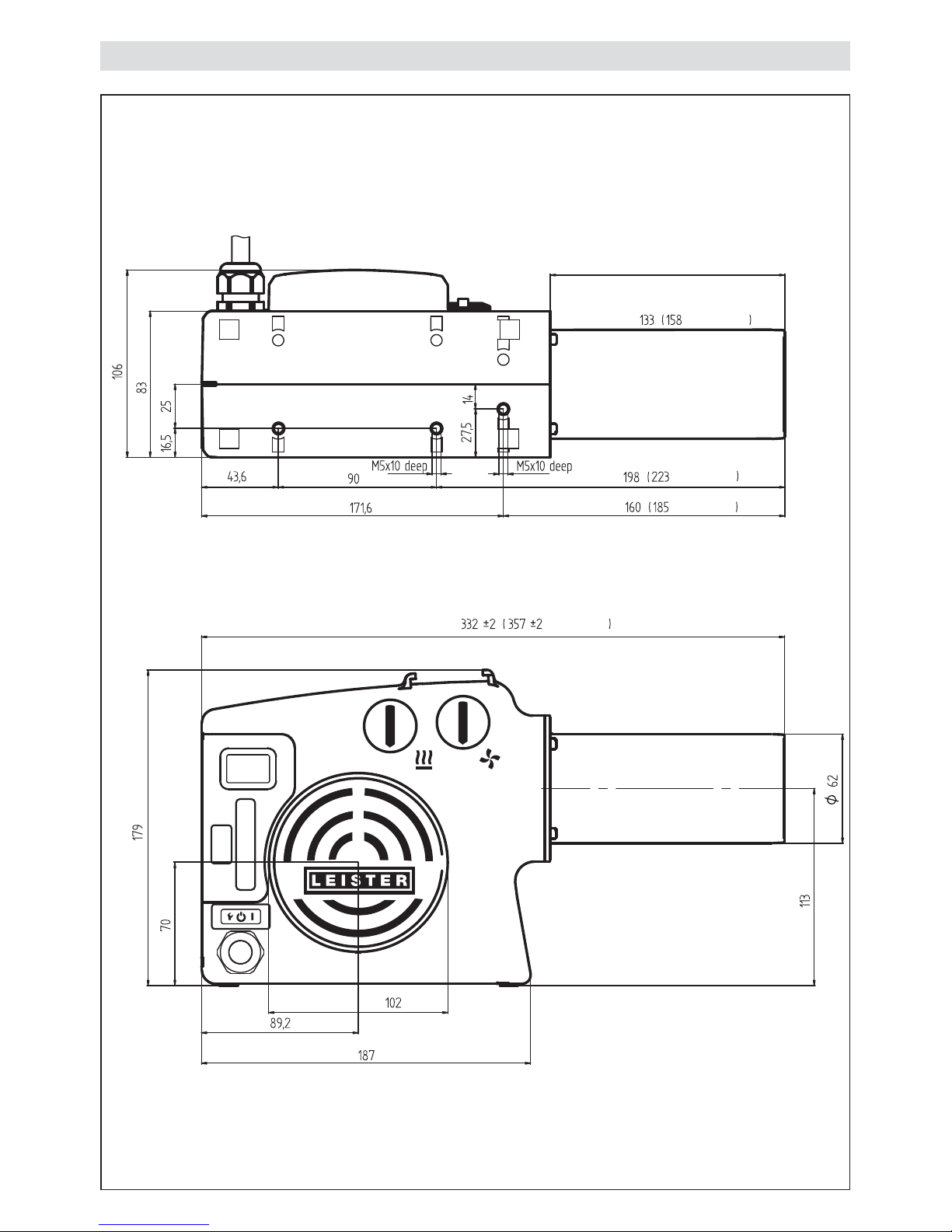
Technische Daten
Spannung V~
120 230 230 230 400
Leistung W
2300 2300 3100 3680 5400
Frequenz Hz
50/60
Max. Luftaustritts-
temperatur
°C
650 650 800 650 650
Luftmenge (20 °C) l/min.
200 – 900
Statischer Druck max. Pa
820 1050
Emissionspegel LpA(dB)
< 70
Gewicht kg
ohne Netzanschlussleitung
2.2 2.2 2.3 2.2 2.4
Masse Seite 3 (Size)
Konformitätszeichen
2
Sicherheitszeichen
3
Schutzklasse II
4
Technische Änderungen vorbehalten
Anschlussspannung nicht umschaltbar
PREMIUM SYSTEM
Heizleistung und Luftmenge mit Potentiometer stufenlos einstellbar • •
Integrierte Leistungselektronik • •
Schutz vor Heizelement- und Geräteüberhitzung • •
Alarmausgang •
Integrierter Temperaturregler •
Fernsteuer-Schnittstelle für Temperatur- oder Leistungsvorgabe •
Fernsteuer-Schnittstelle für Luftmengenvorgabe •
Integrierte Temperatursonde •
Display zur Anzeige der Soll- und Ist-Werte (°C oder °F) •

7
PREMIUM, SYSTEM
Relaisausgang
Max. Spannungen AC 250 V, DC 30 V
Max. Ströme AC 3 A, DC 3 A
Max. Kontaktwiderstand 100 m Ohm bei DC 6 V / 1 A
Kontaktart SPST - NO
Isolation IEC/EN 60065 AC 2000 V (50 - 60 Hz) 1 min
Technische Daten Schnittstelle
Open Loop oder Closed Loop
Stellfunktion Leistung
Stellgrad OFF…100 %;
1% Schritte
Reglerfunktion Temperatur
Sollwertvorgabe 50 °C…650 °C,
5 °C Schritte
Sollwertvorgabe
Potentiometer oder
Schnittstelle
Internes Potentiometer
Sollwert OFF…100 % oder
50 °C …650 °C
Externe Schnittstelle
Sollwert OFF…100 % oder
50 °C …650 °C
SYSTEM
Signaleingänge
mit Verpolungsschutz und
Nullpunktkorrektur
Isolation IEC/EN 60747-5-2
AC 1414 V Peak
Spannungseingang Uc bezogen
auf GND iso
DC 0 - 10 V
(Rippel < 0.05 V bei
5 °C Auflösung)
(Rippel < 0.1 V bei
1 % Auflösung)
Max. Eingangsspannung
DC 12 V
Nenn-Eingangswiderstand
280 kOhm
Stromeingang Ic (2 - Leiter Technik)
DC 4…20 mA
(Rippel < 0.1 mA bei
5 °C Auflösung)
(Rippel < 0.15 mA bei
1 % Auflösung)
Max. Eingangsstrom
DC 22 mA
Nenn-Eingangswiderstand
160 Ohm
Speisung
mit Verpolungsschutz
ohne Trennung von den
Signaleingängen
Betriebsspannung Us bezogen auf
GND iso
DC 15…24 V
Max. Betriebsspannung
DC 25 V
Stromaufnahme
12 mA bei DC 24 V
Potentiometer
Position
0 12345678910
Heizleistung %
OFF 10 20 30 40 50 60 70 80 90 100
Luftmenge l/min
200 270 340 410 480 550 620 690 760 830 900
Temperatur (3680 W)
bei 300 l/min °C
Umgebung 90 150 215 275 340 400 465 525 590 650
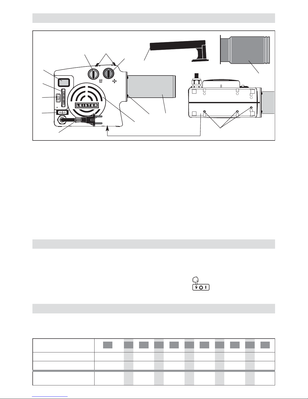
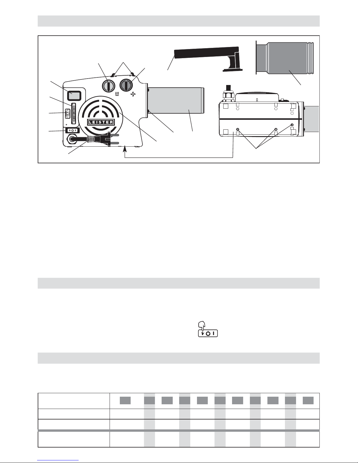
Gerätebeschreibung
HOTWIND PREMIUM oder SYSTEM
1 Netzanschlussleitung
2 Hauptschalter mit Funktionstaste
3 Potentiometer für Temperatur (rot)
4 Potentiometer für Luftmenge (blau)
5 Heizelementrohr
6 Lufteinlassflansch für Edelstahlfilter
7 Halterung für Handgriff
8 Vier Befestigungsschrauben
9 Drei Gewindeeinsätze M5 zur Befestigung
für den Einbau
HOTWIND SYSTEM
10 Display
11 Alarmkontakt
12 Schnittstelle
Handgerät HOTWIND PREMIUM oder SYSTEM
13 Handgriff
14 Schutzrohr
8
• Überhitzt das Heizelement oder Gerät (zu warme Ansaugluft oder Wärmerückstau), wird die Leistungszufuhr
zum Heizelement unterbrochen und der Arbeitskontakt des Alarmrelais geöffnet.
Sprechen Heizelementschutz oder Geräteschutz an, ist aus Sicherheitsgründen ein Rückstellen (Reset) des
HOTWIND’ nötig. Dies geschieht durch Drücken der Funktionstaste (2) während drei Sekunden.
Ansaugluft überprüfen (siehe Einbau).
Funktion Heizelement- und Geräteschutz
10
9
8
7
6
5
4
3
2
1
0
10
9
8
7
6
5
4
3
2
1
0
1
2
9
5
4
3
10
6
11
12
7
14
13
8
• Die interne Elektronik begrenzt die maximale Luftaustrittstemperatur auf 650 °C.
• Es sind Richtwerte welche aufgrund der Umgebungsbedingungen und Bauteiltoleranzen abweichen können.
Einstellwerte Potentiometer
9
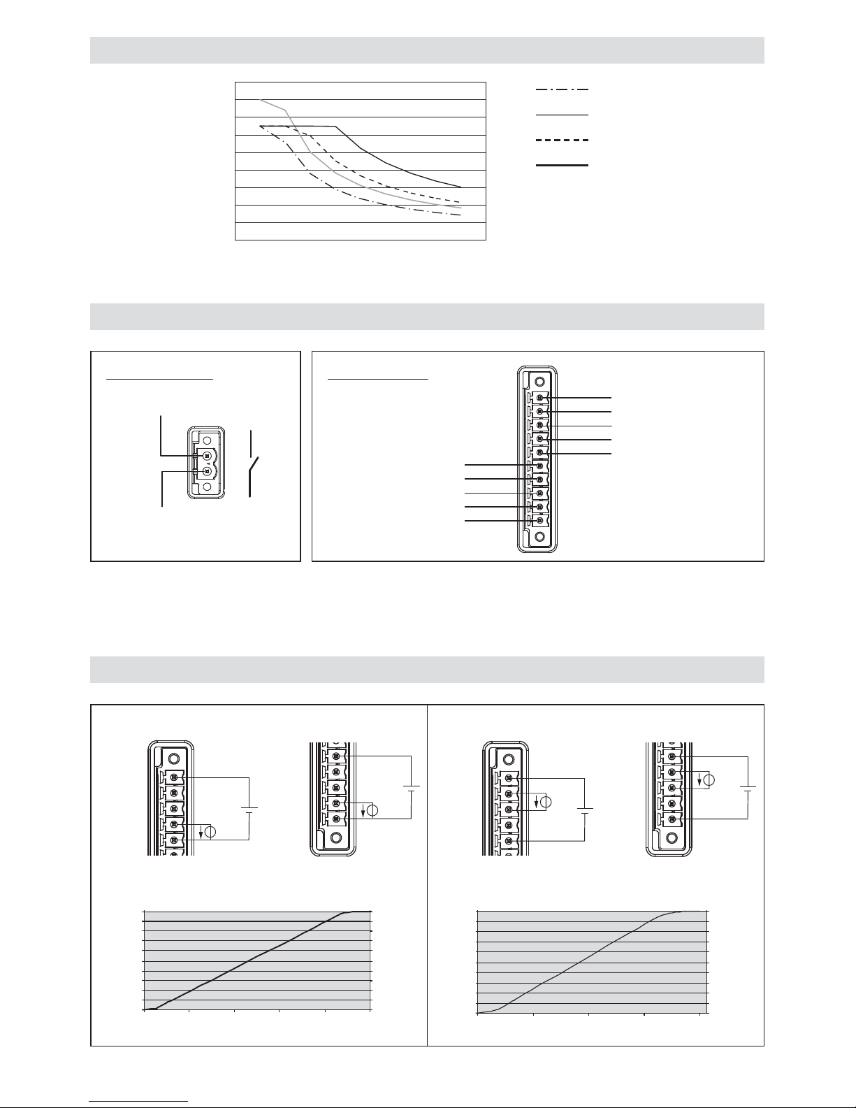
HOTWIND SYSTEM Schnittstelle
11 Alarmkontakt 12 Schnittstelle
Heizleistung
15 - 24 VDC
4 - 20 m A –
4 - 20 m A +
0 -10 V
GND
COM
NO
Im Netzanschluss muss eine geeignete Vorrichtung zur allpoligen Trennung vom Netz mit einem Kontaktabstand
von 3 mm vorhanden sein.
Alarmkontakt: SPST–NO 250 VAC / 30 VDC, 3 A cos = 1
Luftmenge
15 - 24 VDC
4 - 20 m A –
4 - 20 m A +
0 -10 V
GND
Temperatur- / Luftmengen-Diagramm
Temperatur °C
Luftmenge l/min
2300 W
3100 W
3680 W
5400 W
0
100
200
300
400
500
600
700
800
900
0 100 200 300 400 500 600 700 800 900 1000
Achtung: Bei 0 % Luftmenge ca. 200 l/min
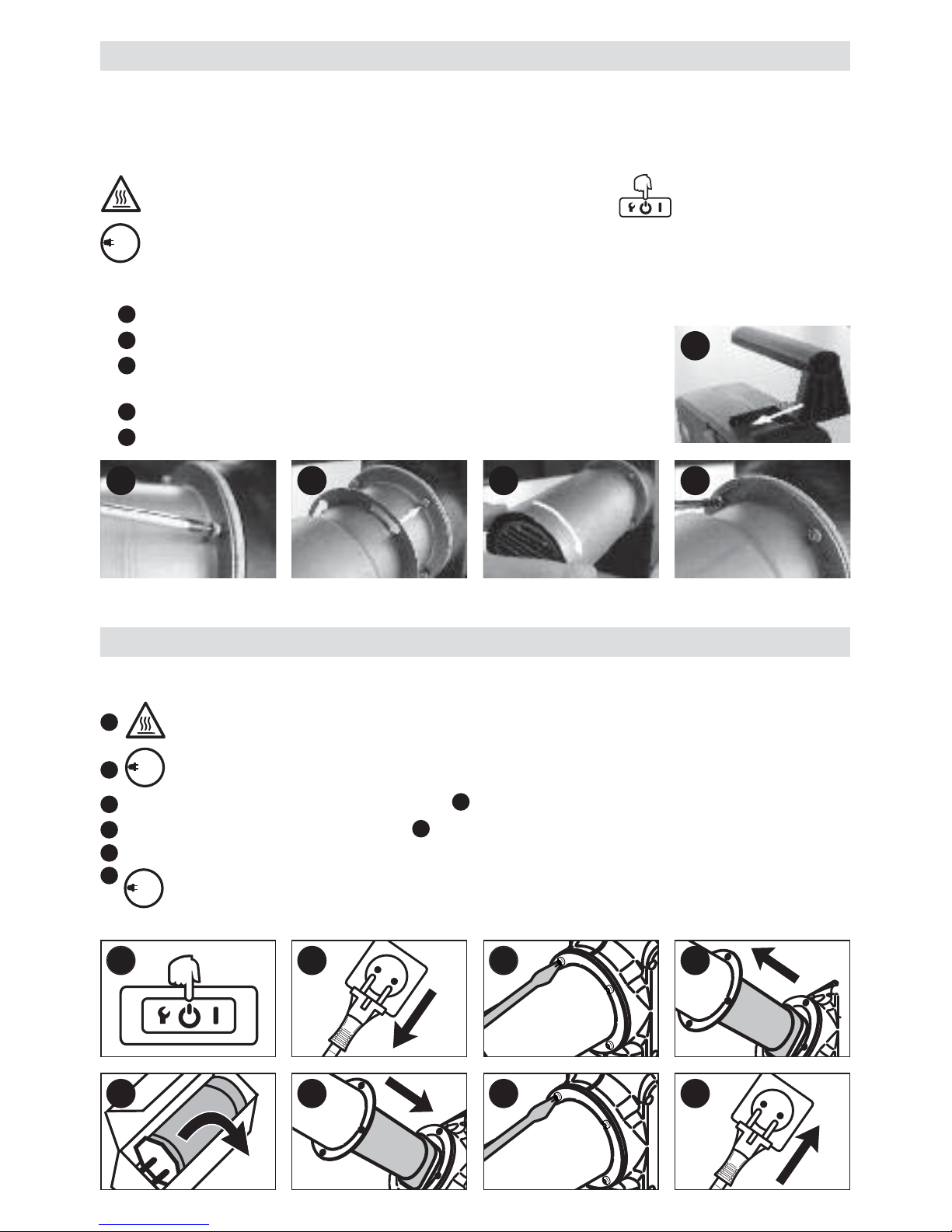
HOTWIND SYSTEM Ansteuerung
Input 0 – 10 V
Us
U
c
0
-
10V
4
-20
m
A –
2
4VDC
4-20mA
+
GND
U
s
Uc
0-10V
4
-20mA –
24VDC
4
-20mA +
G
ND
100
90
80
70
60
50
40
30
20
10
0
0
2
4
6
8
10
100
90
80
70
60
50
40
30
20
10
0
Leistung f (Steuerspannung)
Spannung [V]
Heizleistung [%]
Luftmenge [%]
100
90
80
70
60
50
40
30
20
10
0
4
8
12
16
20
100
90
80
70
60
50
40
30
20
10
0
Leistung f (Steuerstrom)
Strom 4 – 20 [mA]
Heizleistung [%]
Luftmenge [%]
Heizleistung Luftmenge
Input 4 – 20 mA
0-10V
4
-20
mA –
24
VDC
4-20mA
+
GND
Us
Ic
0
-1
0V
4-20mA
–
24VDC
4
-20
mA +
GN
D
Us
Ic
Heizleistung
Luftmenge
10
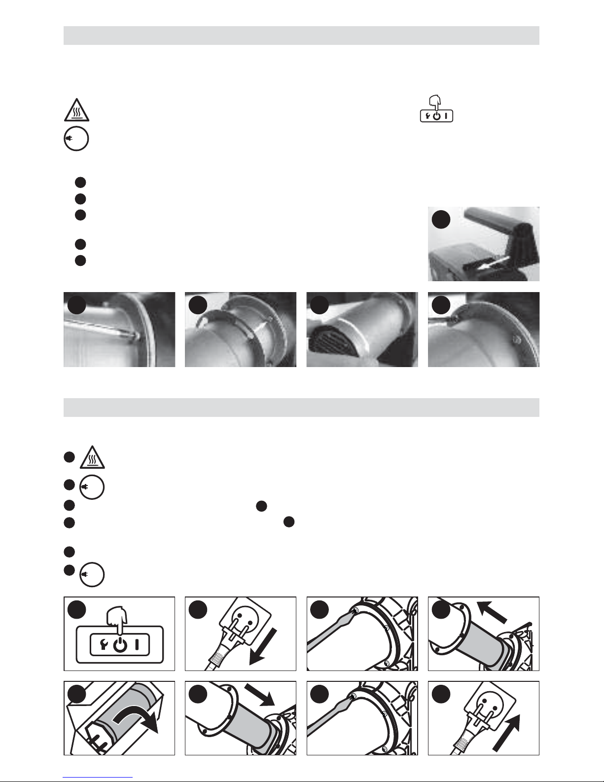
Handle Kit
• Die Montage des Handle Kit darf nur von ausgebildeten Fachleuten oder unter deren Aufsicht vorgenommen
werden.
• Handgriff (13) und Schutzrohr (14) sind im Lieferumfang nicht inbegriffen (siehe Zubehör).
Vor der Montage des Handle Kit das Gerät mittels Hauptschalter (2) ausschalten und abkühlen
lassen. Gerät schaltet automatisch ab.
Netzanschlussleitung (1) vom elektrischen Netz trennen.
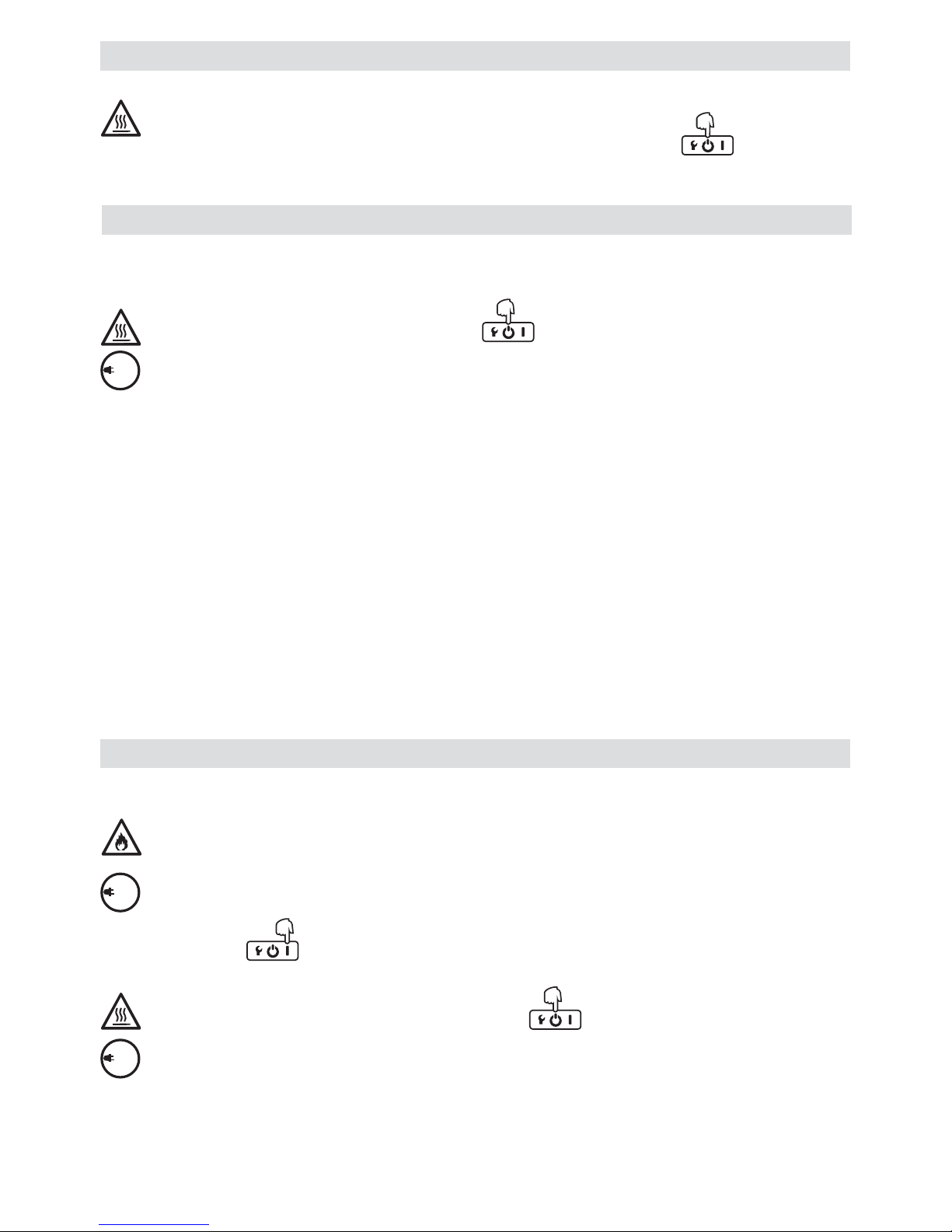
• Montage Handle Kit
Handgriff (13) auf die Halterung (7) schieben.
Die vier Befestigungsschrauben (8) lösen (nicht entfernen).
Schutzrohr (14) auf Heizelementrohr (5) schieben und in die Öffnung für
Befestigungsschrauben (8) einfahren.
Schutzrohr (14) bis zum Anschlag drehen.
Die vier Befestigungsschrauben (8) festziehen.
2 3 4 5
1 2 3 4
Heizelement-Wechsel
1
2
3
4
5
5 6 7 8
•
De
r He
ize
lem
en
t-W
ech
se
l da
rf n
ur v
on
au
sge
bild
ete
n F
ach
leu
ten
od
er u
nte
r d
ere
n A
ufs
icht
vo
rge
nom
m
en
we
rde
n.
Ha
up
tsc
hal
ter
(2)
au
ssc
ha
lten
un
d G
erä
t a
bkü
hle
n l
ass
en.
Ge
rät
sch
alt
et a
uto
ma
tisc
h a
b.
N
etz
an
sch
lus
sle
itu
ng
(1)
vo
m
elek
tris
ch
en
Net
z tr
enn
en
.
Die
vi
er
Bef
est
igu
ng
ssc
hra
ub
en
(8)
en
tfe
rne
n.
He
ize
lem
e
ntro
hr
(5)
un
d H
eiz
ele
me
nt e
ntf
ern
en.
Hei
zele
me
nt
aus
de
r V
erp
ack
un
g n
ehm
en
.
Hei
zel
eme
nt
mo
ntie
ren
un
d
He
izel
em
en
tro
hr (
5)
auf
sch
ieb
en.
He
ize
lem
en
tro
hr
(5)
mi
t vi
er
Bef
es
tigu
ng
sch
ra
ube
n (
8)
mo
ntie
ren
.
N
etz
ans
ch
lus
sle
itu
ng
(1)
an
da
s e
lek
tris
che
N
etz
an
sch
lies
se
n. N
en
ns
pan
nu
ng,
die
au
f d
em
Ger
ät
ang
eg
ebe
n i
st,
mu
ss
mi
t de
r N
etz
sp
ann
un
g ü
ber
ein
stim
m
en
.
1
2
3
4
5
6
7
1
8
120
230
120
230
120
230
11
• Gerät darf nur von ausgebildeten Fachleuten eingebaut werden.
• Einbaumasse siehe Seite 3, Masse / Size.
Vor dem Einbau Gerät mittels Hauptschalter (2) ausschalten und abkühlen lassen.
Gerät schaltet automatisch ab.
Netzanschlussleitung (1) vom elektrischen Netz trennen.
• Es muss sichergestellt sein, dass die Anschlussleitungen das Heizelementrohr nicht berühren und nicht dem
Heissluftstrahl ausgesetzt sind.
• Gerät muss mit drei M5-Schrauben an den Gewindeeinsätzen (9) befestigt werden.
• Der Einbau muss gewährleisten, dass
– nur kalte Luft zugeführt wird
– kein (Wärme-) Rückstau entsteht
– das Gerät nicht vom Heissluftstrahl eines anderen Gerätes angeströmt wird.
• Bei staubhaltiger Luft Leister-Edelstahlfilter (siehe Zubehör) verwenden und auf den Lufteinlassflansch (6) schieben.
• Bei besonders kritischen Stäuben (z.B. Metall-, elektrisch leitende, oder feuchte Stäube) müssen spezielle Filter
verwendet werden, um Kurzschlüsse im Gerät zu vermeiden.
• Das Gerät vor mechanischen Vibrationen und Erschütterungen schützen.
Einbau
Betrieb
• Nach Bedarf entsprechende Düse oder Reflektor montieren.
Es muss darauf geachtet werden, dass die Heissluft frei ausströmen kann, da ansonsten durch Wärmerückstau das Gerät Schaden erleiden kann (Brandgefahr !).
Netzanschlussleitung (1) an das elektrische Netz anschliessen. Nennspannung, die auf dem Gerät
angegeben ist, muss mit der Netzspannung übereinstimmen.
• Hauptschalter (2) einschalten
Gerät nach dem Heizbetrieb mittels Hauptschalter (2) ausschalten und abkühlen lassen.
Gerät schaltet automatisch ab.
Netzanschlussleitung (1) vom elektrischen Netz trennen.
• ACHTUNG: Bei Verwendung als Einbaugerät muss im Netzanschluss eine geeignete Vorrichtung zur allpoligen
Trennung vom Netz mit einem Kontaktabstand von 3 mm vorhanden sein.
120
230
120
230
120
230
Verbrennungsgefahr! Heizelementrohr und Düse nicht in heissem Zustand berühren.
Beim Wechseln der Düse oder Reflektor zuvor Gerät mittels Hauptschalter (2) ausschalten und
abkühlen lassen. Gerät schaltet automatisch ab.
Düsen- / Reflektor-Wechsel
12
Im Menü Setup entsprechende Einstellungen vornehmen (siehe Seite 13).
• Interne Regelung (Closed Loop)
– Temperatur mit rotem Potentiometer (3) einstellen.
– Luftmenge mit blauem Potentiometer (4) einstellen.
• Externe Regelung (Closed Loop)
– Temperatur mittels externem Regler einstellen.
– Luftmenge mittels externem Regler einstellen.
• Interne Steuerung (Open Loop)
– Leistungs-Sollwert mit rotem Potentiometer (3) für
Temperatur einstellen.
– Luftmengen-Sollwert mittels blauem Potentiometer (4)
für Luftmenge einstellen.
• Externe Steuerung (Open Loop)
– Leistungs-Sollwert mittels externem Regler für
Temperatur einstellen.
– Luftmengen-Sollwert mittels externem Regler
für Luftmenge einstellen.
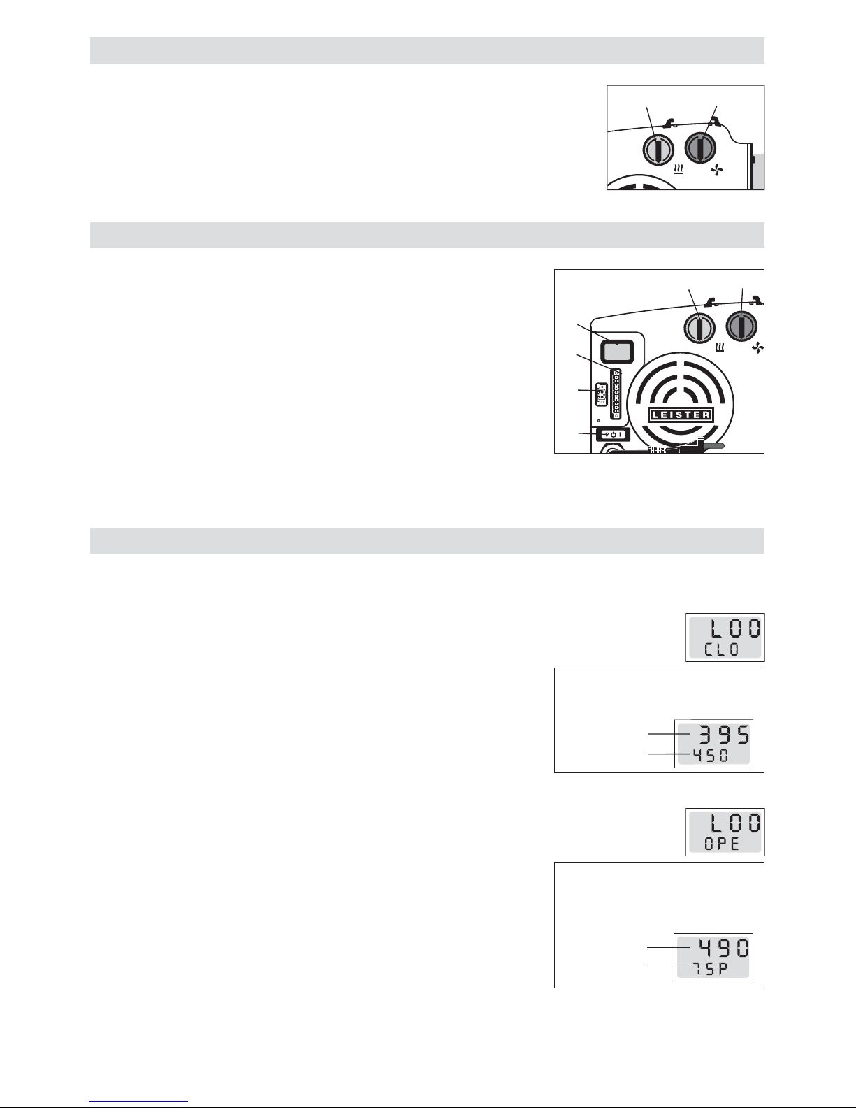
Display (10) HOTWIND SYSTEM
• Temperatur mit rotem Potentiometer (3) einstellen.
• Luftmenge mit blauem Potentiometer (4) einstellen.
Bedienung HOTWIND PREMIUM
Potentiometer
• Temperatur mit rotem Potentiometer (3) einstellen.
• Luftmenge mit blauem Potentiometer (4) einstellen.
Systemschnittstelle
• Die Temperatur und Luftmenge kann über die Systemschnittstelle (12)
gesteuert werden. Der Alarm kann über den Alarm- Relaisausgang (11)
des Gerätes angeschlossen werden.
Das Potentiometer für Temperatur (3) und das Potentiometer für
Luftmenge (4) haben keine Funktion mehr.
• Für Umstellung zwischen Potentiometer oder Schnittstelle siehe Konfiguration Seite 13.
Bedienung HOTWIND SYSTEM
10
9
8
7
6
5
4
3
2
1
0
10
9
8
7
6
5
4
3
2
1
0
43
10
9
8
7
6
5
4
3
2
1
0
10
9
8
7
6
5
4
3
2
1
0
4
3
2
10
11
12
°C
Istwert
Sollwert
°C
Istwert
Sollwert %
Das Display zeigt Ist- und
Sollwert der Temperatur an
Das Display zeigt den
Leistungssollwert in % und den
Istwert der Temperatur an
°C
Closed Loop
Open Loop
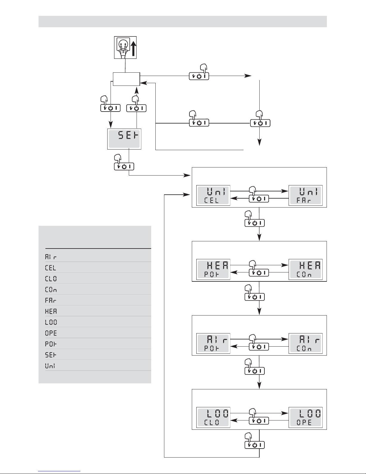
13
Funktionstaste (2)
3 Sekunden drücken
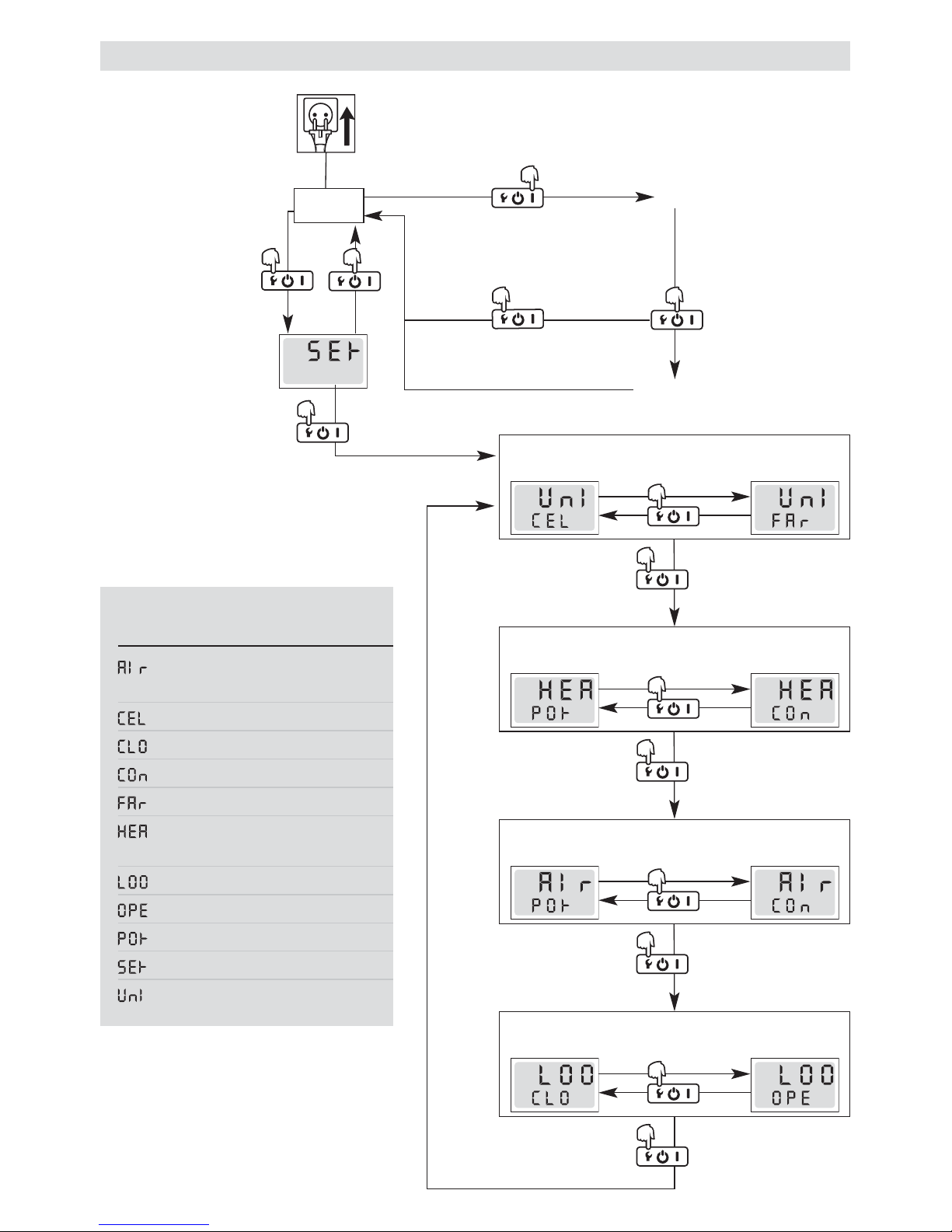
Menü Setup
Netzanschlussleitung (1)
an das elektrische Netz an-
schliessen
Stand by
Hauptschalter (2)
EIN
Heizung
Cool Down
3 Minuten
Funktionstaste (2)
3 Sekunden drücken
Konfiguration und Bedienung HOTWIND SYSTEM
Funktionstaste (2)
1 x kurz drücken
Funktionstaste (2)
3 Sekunden drücken
Funktionstaste (2)
1 x kurz drücken
°C
°F
Funktionstaste (2)
3 Sekunden drücken
Funktionstaste (2)
1 x kurz drücken
Funktionstaste (2)
3 Sekunden drücken
Funktionstaste (2)
1 x kurz drücken
Funktionstaste (2)
3 Sekunden drücken
Funktionstaste (2)
1 x kurz drücken
°C
L e g e n d e
Anzeige Beschreibung
(Air) Sollwert Luftmenge
(°C) Celsius
(Closed Loop) Geregelt
(Connector) Schnittstelle
(°F) Fahrenheit
(Heater) Sollwert Heizung
(Loop) Regelung
(Open Loop) Gesteuert
(Pot) Potentiometer
(Setup) Konfiguration
(Unit) Einheit
Wird im Menü Setup 10 Sekunden die
Funktionstaste (2) nicht gedrückt schaltet
das Gerät automatisch auf Stand by
14
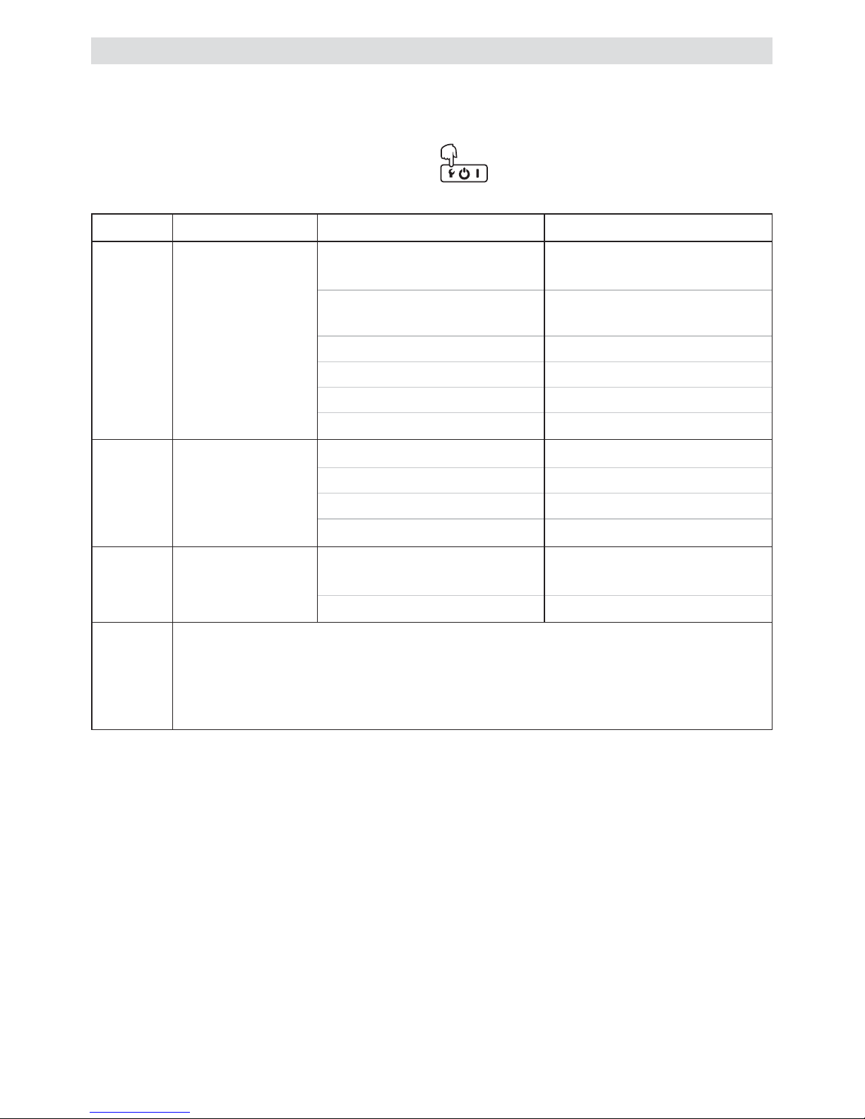
•
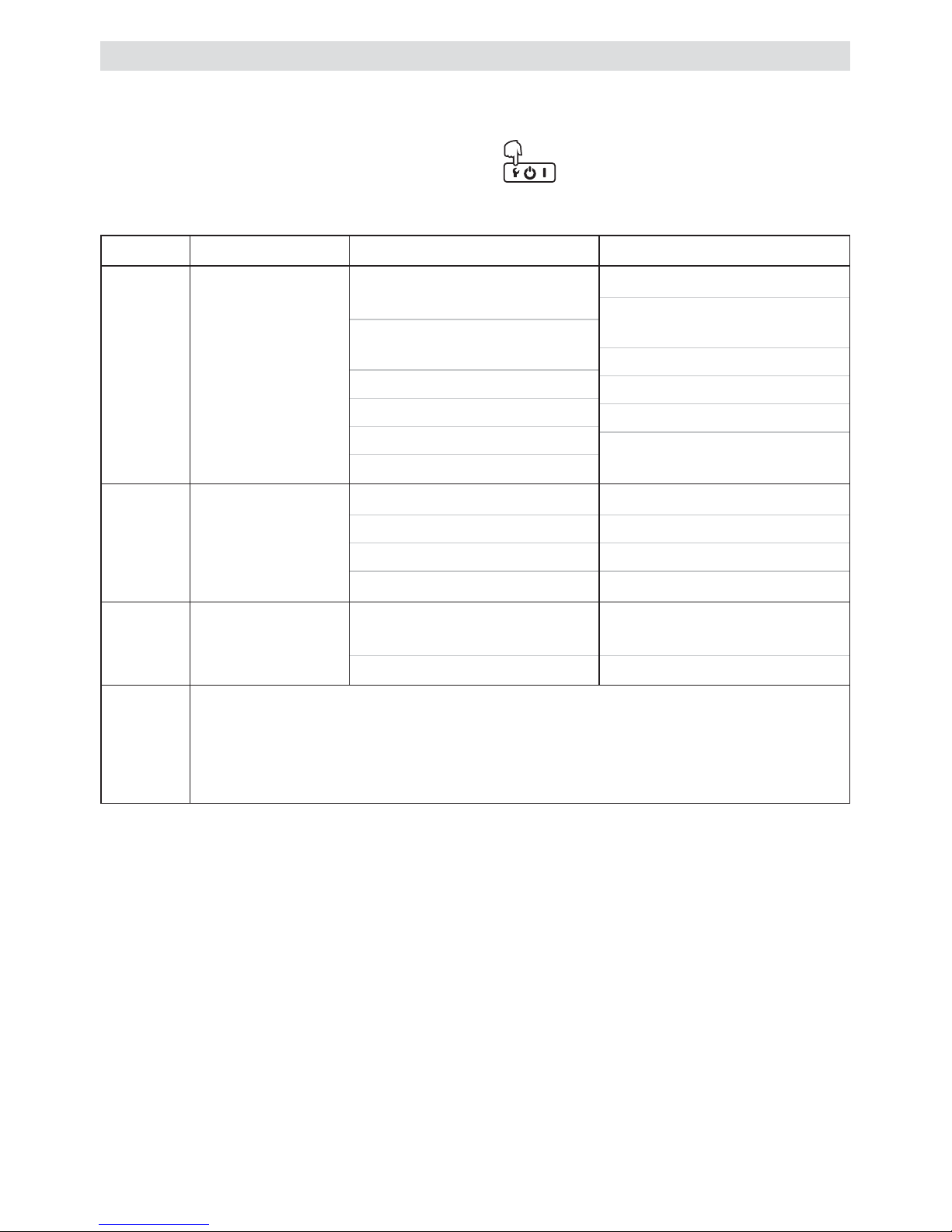
Wenn eine Fehlfunktion des Gerätes auftritt, erscheint auf dem Display (10) eine Meldung, welche zu sätzlich
mit einem Error-Code versehen ist. Dieser Code steht für eine genauere Um schreibung des Fehlers (siehe Tabelle).
• Ein Error kann durch Drücken der Funktionstaste (2) während drei Sekunden zurückgesetzt werden
(Reset).
Error
Display
Bezeichnung Fehlerursache Fehlerbehebung
Err 01 Gerätetemperatur
zu hoch
Umgebungstemperatur grösser als
spezifiziert
Zulufttemperatur grösser als
spezifiziert
Lufteinlass blockiert
Edelstahlfilter blockiert
Luftauslass blockiert
Falsche Düse montiert
Umgebungstemperatur
reduzieren
Zulufttemperatur reduzieren
Lufteinlass überprüfen
Edelstahlfilter reinigen
Luftauslass überprüfen
Düse kontrollieren
Err 02 Heizelement -
temperatur zu
hoch
Lufteinlass blockiert
Edelstahlfilter blockiert
Luftauslass blockiert
Falsche Düse montiert
Lufteinlass überprüfen
Edelstahlfilter reinigen
Luftauslass überprüfen
Düse wechseln
Err 03 Temperatursonde Anschluss Temperatursonde
fehlerhaft
Temperatursonde defekt
Anschluss der Temperatursonde
kontrollieren
Leister Service-Stelle kontaktieren
Err 04
Err 05
Err 06
Err 07
Err 08
Leister Service-Stelle kontaktierten

15
• Es darf nur Leister-Zubehör verwendet werden !
Handle Kit Artikel No. 141.723
Edelstahl Filter Artikel No. 107.248
• Weitere Zubehör unter www.leister.com
• Leister Technologies AG und deren autorisierte Service-Stellen bieten kostenlos Schweiss kurse und Einschulungen
an. Informationen unter www.leister.com.
• Der Lufteinlass (6) ist bei Verschmutzung mit einem Pinsel zu reinigen
• Netzanschlussleitung (1) und Stecker auf elektrische und mechanische Beschädigungen
überprüfen
• Reparaturen sind ausschliesslich von autorisierten Leister-Service-Stellen ausführen zu lassen. Diese gewähr-
leisten innert nützlicher Frist einen fachgerechten und zuverlässigen Reparatur-Service mit Original-Ersatzteilen
gemäss Schaltplänen und Ersatzteillisten.
• Für dieses Gerät gelten die vom direkten Vertriebspartner/Verkäufer gewährten Garantie- oder Gewährleistungsrechte
ab Kaufdatum. Bei einem Garantie- oder Gewährleistungsanspruch (Nachweis durch Rechnung oder Lieferschein)
werden Herstellungs- oder Verarbeitungsfehler vom Vertriebspartner durch Ersatzlieferung oder Reparatur beseitigt.
Heizelemente sind von der Gewährleistung oder Garantie ausgeschlossen.
• Weitere Garantie- oder Gewährleistungsansprüche werden im Rahmen des zwingenden Rechts ausgeschlossen.
• Schäden, die auf natürliche Abnutzung, Überlastung oder unsachgemässe Behandlung zurückzuführen sind, werden
von der Gewährleistung ausgeschlossen.
• Keine Garantie- oder Gewährleistungsansprüche bestehen bei Geräten, die vom Käufer umgebaut oder verändert
wurden.
Gewährleistung
Schulung
Service und Reparatur
Wartung
Zubehör
Operating Instructions
(Translation of the original operating instructions)
16
Hot air blower
HOTWIND PREMIUM, HOTWIND SYSTEM
The HOTWIND PREMIUM hot air blower and HOTWIND SYTEM are designed for continuous operation.
They are ideally suited for installation in machines, systems and devices or even as hand devices and table
top units.
Their most important applications include; drying and heating, thawing, accelerating and removal,
sterilising, smoothing, polishing, activation and dissolving, separating and fusing, shrinking, soldering,
welding, removal, kindling..
Application
GB
Please read operating instructions carefully before use
and keep for future reference.
Danger to life when opening the device as live components and connections are
exposed. Unplug the line/mains plug from the plug socket before opening the device.
Incorrect use of the hot air blower can present a fire and explosion hazard
especially near combustable materials and explosive gases.
Danger – can cause burns! Do not touch the heating element tube and nozzle
while they are hot. Allow the device to cool. Do not direct hot-air stream towards
people or animals.
Warning
The device must not be left unattended when in use.
Heat can reach combustible materials which are out of sight. The device may only
be used by trained personnel or under their supervision. Children may not use
the device under any circumstances.
For personal protection, we strongly recommend the tool be connected to an
RCCB (Residual Current Circuit Breaker) before using it on construction sites.
The nominal voltage indicated on the device must correspond to the mains
voltage. EN 61000-3-11; Z
max
= 0.053 + j 0.033 .
If necessary, consult your
electricity supply utility.
Keep away from wet and damp areas.
FI
120
230
Caution
Congratulations on purchasing a HOTWIND !
You have chosen a top-class hot air blower by Leister, made from high-quality materials. Every HOTWIND
undergoes stringent quality checks before leaving the factory in Switzerland.

17
(in terms of the EC machinery directive 2006/42; Appendix II B)
Leister Technologies AG, Galileo-Strasse 10, CH-6056 Kaegiswil/Switzerland hereby declares the partly
completed machinery
Designation: Hot air blower
Type: HOTWIND
Option: PREMIUM or SYSTEM
– as far as it is possible from the scope of supply – fulfills the applicable essential requirements of the EC ma-
chinery directive (2006/42).
The partly completed machinery furthermore complies with the provisions of the following EC directive(s):
EC directive(s): Electromagnetic Compatibility
2004/108 (valid until 19.04.2016), 2014/30 (valid from 20.04.2016)
Low Voltage Directive
2006/95 (valid until 19.04.2016), 2014/35 (valid from 20.04.2016)
RoHS Directive 2011/65
Harmonised standards: EN 12100, EN 55014-1, EN 55014-2, EN 61000-3-2, EN 61000-3-3,
EN 61000-3-11
(Z
max
)
, EN 62233, EN 60335-2-45, EN 50581
In addition, we declare the relevant technical documentation for this partly completed machinery is compiled
in accordance with Annex VII (part B) and will be electronically transmitted to national authorities in response
to a reasoned request. Authorised documentation representative: Volker Pohl, Manager Product Conformity
The partly completed machine must not be put into service until the final machinery into which it is to be
incorporated has been declared in conformity with the provisions of the EC machinery directive (2006/42),
where appropriate.
Kaegiswil, 21.10.2015
Bruno von Wyl, CTO Andreas Kathriner, GM
Power tools, accessories and packaging should be recycled. For EU countries only: do not dispose
of power tools in your household rubbish! According to the European Directive 2012/19/EU on
waste electrical and electric equipment and its implementation in national law, power tools which
can no longer be used must be collected separately and recycled.
Disposal
Installation declaration

18
Technical Data
Voltage V~
120 230 230 230 400
Power consumption W
2300 2300 3100 3680 5400
Frequency Hz
50/60
Max. air outlet
temperature
°C
650 650 800 650 650
Air volume (20 °C) l/min.
200 – 900
Max. static pressure Pa
820 1050
Emission level LpA(dB)
< 70
Weight kg
without power supply cord
2.2 2.2 2.3 2.2 2.4
Dimensions Page 3 (Size)
Mark of conformity
2
Approval mark
3
Protection class II
4
Technical data and specifications are subject to change without prior notice
Mains voltage cannot be switched over
PREMIUM SYSTEM
Heat output and air volume steplessly adjustable with potentiometer • •
Integrated power electronics • •
Protection against heating element or device overheating • •
Alarm output •
Integrated temperature control •
Remote control interface for temperature or power set point •
Remote control interface for air volume adjustment •
Integrated temperature probe •
Display for showing the setpoint and actual values (°C or °F) •

19
PREMIUM, SYSTEM
Relay output
Max. voltages AC 250 V, DC 30 V
Max. currents AC 3 A, DC 3 A
Max. contact resistance 100 m Ohm at DC 6 V / 1 A
Relay contact SPST - NO
Insulation IEC/EN 60065 AC 2000 V (50 - 60 Hz) 1 min
Technical data for interface
Open loop or closed loop
Power setting function
setting level OFF…100 %;
1% steps
Temperature control function
setpoint value specification
50 °C…650 °C, 5 °C steps
Setpoint entry
Potentiometer or interface
Internal potentiometer
setpoint
value OFF…100 % or
50 °C …650 °C
Interface
setpoint
value OFF…100 % or
50 °C …650 °C
SYSTEM
Signal inputs
with reverse polarity protection
and zero point correction
Insulation IEC/EN 60747-5-2
AC 1414 V Peak
Voltage input Uc in relation to GND
iso
DC 0 - 10 V
(Ripple < 0.05 V at
5 °C resolution)
(Ripple < 0.1 V at
1 % resolution)
Max. input voltage
DC 12 V
Nominal input resistance
280 kOhm
Current input Ic (2 - conductor
technology)
DC 4…20 mA
(Ripple < 0.1 mA at
5 °C resolution)
(Ripple < 0.15 mA at
1 % resolution)
Max. input current
DC 22 mA
Nominal input resistance
160 Ohm
Supply
with reverse polarity protection
without separation of the
signal inputs
Operating voltage Us in relation to
GND iso
DC 15…24 V
Max. operating voltage
DC 25 V
Power consumption
12 mA at DC 24 V
Potentiometer
Position
0 12345678910
Heating power %
OFF 10 20 30 40 50 60 70 80 90 100
Air volume l/min
200 270 340 410 480 550 620 690 760 830 900
Temperature (3680 W)
at 300 l/min °C
Environment 90 150 215 275 340 400 465 525 590 650
Device Description
HOTWIND PREMIUM or SYSTEM
1 Power supply cord
2 Main switch with function button
3 Potentiometer for temperature (red)
4 Potentiometer for air volume (blue)
5 Heating element tube
6 Air inlet flange for stainless steel filter
7 Holder for handle
8 Four fastening screws
9 Three M5 thread inserts for fastening
for installation
HOTWIND SYSTEM
10 Display
11 Alarm contact
12 Interface
HOTWIND PREMIUM hand device or SYSTEM
13 Handle
14 Protective tube
20
• If the heating element or device overheats (too hot inlet air or excess heat reside), the power supply to the
heating element will be interrupted and the working contact of the alarm relay opened.
If the heating element or device protection responds, it will be necessary to reset the HOTWIND for reasons
of safety. This occurs by pressing the function button (2) for three seconds. Check inlet air (see
installation).
Function of heating element and device protection
10
9
8
7
6
5
4
3
2
1
0
10
9
8
7
6
5
4
3
2
1
0
1
2
9
5
4
3
10
6
11
12
7
14
13
8
• The internal electronics regulates the maximum outlet air temperature to 650 °C.
• The reference values can be deviated from due to ambient conditions and component tolerances.
Adjustable potentiometer

21
HOTWIND SYSTEM Interface
11 Alarm contact 12 Interface
Heating power
15 - 24 VDC
4 - 20 m A –
4 - 20 m A +
0 -10 V
GND
COM
NO
A suitable device for full disconnection from the mains with a contact distance of 3 mm must be provided in the
mains connection.
Alarm contact: SPST–NO 250 VAC / 30 VDC, 3 A cos = 1
Air volume
15 - 24 VDC
4 - 20 m A –
4 - 20 m A +
0 -10 V
GND
Temperature / air volume diagram
Temperature °C
Air volume l/min
2300 W
3100 W
3680 W
5400 W
0
100
200
300
400
500
600
700
800
900
0 100 200 300 400 500 600 700 800 900 1000
Achtung: Bei 0 % Luftmenge ca. 200 l/min
HOTWIND SYSTEM control
Input 0 – 10 V
Us
U
c
0
-
10V
4
-20
m
A –
2
4VDC
4-20mA
+
GND
U
s
Uc
0-10V
4
-20mA –
24VDC
4
-20mA +
G
ND
100
90
80
70
60
50
40
30
20
10
0
0
2
4
6
8
10
100
90
80
70
60
50
40
30
20
10
0
Power f (control voltage)
Voltage [V]
Heating power [%]
Air volume [%]
100
90
80
70
60
50
40
30
20
10
0
4
8
12
16
20
100
90
80
70
60
50
40
30
20
10
0
Power f (control current)
Current 4 – 20 [mA]
Heating powe [%]
Air volume [%]
Heating power Air volume
Input 4 – 20 mA
0-10V
4
-20
mA –
24
VDC
4-20mA
+
GND
Us
Ic
0
-1
0V
4-20mA
–
24VDC
4
-20
mA +
GN
D
Us
Ic
Heating power Air volume
22
Handle Kit
• The assembly of the handle kit may only be used by trained personnel or under their supervision.
• Handle (13) and protective tube (14) are not included in the scope of supply (see accessories).
Prior to assembly of the handle kit, switch off the unit by the main switch (2) and allow the device
to cool down. Machine switches off automatically.
Disconnect power supply cord (1) form the line/mains.
• Handle kit assembly
Push handle (13) onto the holder (7).
Loosen the four fastening screws (8) (do not remove).
Push the protective tube (14) onto the heating element tube (5)
and move in the opening for fastening screws (8).
Turn the protective tube (14) as far as it will go.
Tighten the four fastening screws (8).
Changing the heating element
1
2
3
4
5
•
C
han
gin
g t
he
hea
tin
g e
lem
en
t m
ay
onl
y be
ca
rri
ed
out
by
tra
ine
d p
ers
onn
el
or u
nd
er t
hei
r su
pe
rvis
ion
.
S
wi
tch
off
th
e m
ain
sw
itc
h
(2)
and
al
low
th
e u
nit
to
coo
l d
ow
n. M
ac
hin
e s
wit
ch
es
off
aut
om
atic
all
y.
D
is
con
ne
ct p
ow
er
su
pp
ly c
ord
(1
) f
orm
th
e l
ine
/ma
ins
.
R
em
ove
th
e fo
ur
fas
ten
ing
sc
re
ws
(8)
.
Re
mo
ve
the
he
ati
ng
ele
me
nt
tub
e (
5)
and
he
ati
ng
ele
me
nt.
T
ake
th
e h
eat
ing
ele
me
nt
out
of
its
pa
cka
gin
g.
A
sse
mb
le
the
he
ati
ng
ele
me
nt a
nd
pu
sh
on
the
he
atin
g
el
em
ent
tu
be
(5)
.
A
sse
mb
le
the
he
ati
ng
ele
me
nt
tub
e (
5)
wit
h fo
ur
fas
ten
in
g s
cre
ws
(8)
.
C
onn
ec
t p
ow
er s
up
ply
co
rd
(1)
to
the
el
ect
rica
l m
ain
s.
The
no
mi
nal
vo
ltag
e i
ndi
cat
ed
on
the
de
vic
e
m
us
t c
orre
sp
ond
to
th
e m
ain
s v
olta
ge
.
1
2
3
4
5
6
7
8
120
230
120
230
120
230
2 3 4 5
1
1 2 3 4
5 6 7 8
23
• The device may only be installed by trained personnel.
• For installation dimensions, see page 3, dimensions/size.
Prior to installation of the device, switch off the unit by the main switch (2) and allow the device
to cool down. Machine switches off automatically.
Disconnect power supply cord (1) form the line/mains.
• It must be ensured that the connection lines do not come into contact with the heating element tube and are not
exposed to the hot air jet.
• The device must be fastened with three M5 screws to the thread inserts.
• The installation must ensure that
– only cold air is supplied
– no excess (heat) residue builds up
– the device is not subject to jets of hot air from another device.
• If the air contains dust use a Leister stainless steel filter (see accessories) and push it on the air inlet flange (6).
• In the case of particularly critical dusts (e.g. metal, electrically conductive or damp dusts), special filters must be
used to avoid short-circuits in the device.
• Protect the device from mechanical vibrations and shocks.
Installation
Operation
• Mount corresponding nozzle or reflector, if required.
It must be ensured that the hot air can flow out freely, as otherwise the device can be damaged by the
excess heat building up (risk of fire !).
Connect power supply cord (1) to the electrical mains. The nominal voltage indicated on the device
must correspond to the mains voltage.
• Switch on main switch (2)
After heating mode, switch off the unit by the main switch (2) and allow the device to cool down.
Machine switches off automatically.
Disconnect power supply cord (1) form the line/mains.
• WARNING: When using as a built-in unit, a suitable device for full disconnection from the mains with a contact
distance of 3 mm must be provided in the mains connection.
120
230
120
230
120
230
Danger – can cause burns ! Do not touch the heating element tube and nozzle while they are hot.
Switch off the main switch (2) and allow the unit to cool down before replacing the nozzle or
reflector.
Machine switches off automatically.
Changing the nozzle or reflector

24
Corresponding settings can be changed via the setup menu (see page 25).
• Internal control (closed loop)
– Set the temperature using the red potentiometer (3).
– Set the air volume using the blue potentiometer (4).
• External control (closed loop)
– Set the temperature using the external controller.
– Set the air volume using the external controller..
• Internal control (open loop)
– Set the power set-point using the red potentiometer (3) for
the temperature.
– Set the air volume set-point using the blue potentiometer (4)
for air volume.
• External control (open loop)
– Set the power set-point using the external controller for
temperature.
– Set air volume set-point using the external controller
for air volume.
HOTWIND SYSTEM display (10)
• Set the temperature using the red potentiometer (3).
• Set the air volume using the blue potentiometer (4).
HOTWIND PREMIUM operation
Potentiometer
• Set the temperature using the red potentiometer (3).
• Set the air volume using the blue potentiometer (4).
System interface
• The temperature and the air volume can be controlled via the system in-
terface (12). The alarm can be connected via the units’ alarm relay
output (11).
The potentiometer for temperature (3) and the potentiometer for
air volume (4) no longer function.
• For switching between potentiometer or interface, see configuration, page 25.
HOTWIND SYSTEM operation
10
9
8
7
6
5
4
3
2
1
0
10
9
8
7
6
5
4
3
2
1
0
43
10
9
8
7
6
5
4
3
2
1
0
10
9
8
7
6
5
4
3
2
1
0
4
3
2
10
11
12
°C
Actual value
Set point value
°C
Actual value
Set point value %
The display shows the actual and
set point of the temperature
The display shows the capacity
set point in % and the actual value
of the temperature
°C
Closed Loop
Open Loop
25
Function button (2)
Press for 3 seconds-
Set up menu
Establish power supply
cord (1) to the electrical
mains.
Stand by
Function button (2)
ON
Heating
Cool Down
3 minutes
Function button (2)
Press for 3 seconds
HOTWIND SYSTEM configuration and operation
Function button (2)
1 x short press
Function button (2)
Press for 3 seconds
Function button (2)
1 x short press
°C
°F
Function button (2)
Press for 3 seconds
Function button (2))
1 x short press
Function button (2)
Press for 3 seconds
Function button (2)
1 x short press
Function button (2)
Press for 3 seconds
Function button (2)
1 x short press
°C
L e g e n d
Display Description
(Air) Set point value –
air volume
(°C) Celsius
(Closed Loop) Regulated
(Connector) Interface
(°F) Fahrenheit
(Heater) Set point value –
heating
(Loop) Control
(Open Loop) Controlled
(Pot) Potentiometer
(Setup) Configuration
(Unit) Unit
If in the set up menu the function button (2)
is not pressed for 10 seconds, the unit
automatically switches to stand by
26
• If a malfunction occurs in the unit, a message accompanied by an error code will appear on the display (10).
This code stands for a more precise definition of the error (see table)
• An error can be reset by pressing the function button (2) for 3 seconds.
Error
Display
Designation Cause of error Troubleshooting
Err 01 Unit temperature too
high
Ambient temperature higher than
specified
Inlet air temperature higher than
specified
Air inlet blocked
Stainless steel filter blocked
Air outlet blocked
Incorrect nozzle installed
Reduce ambient temperature
Reduce inlet air temperature
Check air inlet
Clean stainless steel filter
Check air outlet
Monitor nozzle
Err 02 Heating element
temperature
too high
Air inlet blocked
Stainless steel filter blocked
Air outlet blocked
Incorrect nozzle installed
Check air inlet
Clean stainless steel filter
Check air outlet
Replace nozzle
Err 03 Temperature probe Temperature probe connection
faulty
Temperature probe defective
Monitor the connection of the
temperature probe
Contact Leister service point
Err 04
Err 05
Err 06
Err 07
Err 08
Contact Leister service point

27
• Only Leister accessories should be used
Handle kit Article no. 141.723
Stainless steel filter Article no. 107.248
• Further accessories at www.leister.com
•
Leister Technologies AG and its authorised Service Centres offer free welding courses and training.
Informationen below www.leister.com.
• The air inlet (6) must be cleaned with a brush if soiled
• Check power supply cord (1) and plug for electrical and mechanical damage.
• Repairs should only be carried out by authorised Leister Service Centres. They guarantee a correct and reliable
repair service within reasonable period, using original spare parts in accordance with the circuit diagrams and
spare parts lists.
• For this tool, the guarantee or warranty rights granted by the relevant distributor/seller shall apply. In case of guarantee or warranty claims any manufacturing or workmanship defects will either be repaired or replaced by the
distributor at its discretion. Warranty or guarantee rights have to be verified by an invoice or a delivery document.
Heating elements shall be excluded from warranty or guarantee.
• Additional guarantee or warranty claims shall be excluded, subject to mandatory provisions of law.
• Warranty or guarantee shall not apply to defects caused by normal wear and tear, overload or improper handling.
• Warranty or guarantee claims will be rejected for tools that have been altered or changed by the purchaser.
Warranty
Training
Service and Repairs
Maintenance
Accessories
Istruzioni per l'uso
(Traduzione del manuale di istruzioni originale)
28
Soffiatrice di aria calda
HOTWIND PREMIUM, HOTWIND SYSTEM
La soffiatrice di aria calda HOTWIND PREMIUM e la soffiatrice HOTWIND SYSTEM sono progettate per garantire il
funzionamento continuo. Si adattano alla perfezione all'installazione in macchine, impianti e apparecchiatura o
anche come dispositivi portatili e strumentazioni da banco.
Le sue più importanti applicazioni sono ad esempio essiccazione e riscaldamento, scongelamento, accelerazione e miscelazione, sterilizzazione, levigatura, lucidatura, attivazione e allentamento, separazione e fusione, termoretrazione, saldatura, rimozione ed accensione.
Aplication
I
Prima dell'attivazione leggere con attenzione le istruzioni
per l'uso e conservarle per ulteriori consultazioni.
Aprendo l'apparecchio è presente il pericolo di morte perché vengono esposti
componenti e collegamenti sotto tensione. Estrarre la spina elettrica prima di
procedere all'apertura dell'apparecchio.
È presente il pericolo di incendio e di esplosione in caso di utilizzo non conforme
degli apparecchi ad aria calda, in particolare nelle vicinanze di materiali infiammabili
e gas esplosivi.
Pericolo di ustione! Non toccare il tubo della resistenza e l'ugello quando
sono ancora ad alte temperature. Lasciar raffreddare l'apparecchio.
Non orientare il getto di aria calda verso persone o animali.
Avvertenze
È necessario mantenere l'apparecchio sotto controllo durante il funzionamento. Il
calore può raggiungere materiali infiammabili che si trovano fuori dal campo visivo.
L'impiego dell'apparecchio è consentito esclusivamente a personale specializzato
o sotto il monitoraggio di quest'ultimo. È tassativamente vietato l'impiego da parte
dei bambini.
Se si utilizza l'apparecchio in cantiere, sono tassativamente necessari gli interruttori
per correnti di guasto per garantire la tutela del personale.
La tensione nominale specificata sull'apparecchio deve coincidere con la tensione
di rete. EN 61000-3-11; Z
max
= 0.053 + j 0.033 . In caso di necessità
consultare l'azienda addetta all'erogazione della corrente elettrica.
Proteggere l'apparecchio da umidità e da ambienti bagnati.
FI
120
230
Cautela
Congratulazioni per l’acquisto di HOTWIND !
È stato scelta un'eccellente soatrice d'aria calda di Leister realizzata con materiali di alta qualità. Prima di uscire
dallo stabilimento in Svizzera, tutti i modelli di HOTWIND sono sottoposti ad un rigoroso controllo di qualità.
29
(ai sensi della direttiva CE in materia di macchinari 2006/42, nota integrativa II B)
Con il presente documento
Leister Technologies AG, Galileo-Strasse 10, CH-6056 Kaegiswil / Svizzera
dichiara che la macchina incompleta
Descrizione: Hot air blower
Modello: HOTWIND
Versione: PREMIUM o SYSTEM
– soddisfa i requisiti fondamentali applicabili della direttiva in materia di macchinari CE (2006/42), a seconda delle
possibilità previste dalla fornitura.
La macchina incompleta soddisfa inoltre i requisiti della/e direttiva/e CE riportata/e di seguito:
Direttiva/e CE: compatibilità elettromagnetica
2004/108 (scade 19.04.2016), 2014/30 (valido dal 20.04.2016)
direttiva in materia di basse tensioni
2006/95 (scade 19.04.2016), 2014/35 (valido dal 20.04.2016)
RoHS direttiva 2011/65
Normative armonizzate: EN 12100, EN 55014-1, EN 55014-2, EN 61000-3-2, EN 61000-3-3,
EN 61000-3-11
(Z
max
)
, EN 62233, EN 60335-2-45, EN 50581
Inoltre si dichiara di aver prodotto la documentazione tecnica speciale ai sensi della nota integrativa VII (sez.
B) per la presente macchina incompleta con l'obbligo di fornirla su espressa richiesta in formato elettronico
alle autorità competenti del monitoraggio del mercato.
Nominativo del responsabile della documentazione: Volker Pohl, Manager Product Conformity
L'attivazione della macchina incompleta è vietata fino quando non sia stato eventualmente stabilito che la macchina, in cui è stata installata la macchina incompleta, soddisfi le disposizioni della direttiva in materia di macchinari
CE (2006/42).
Kaegiswil, 21.10.2015
Bruno von Wyl, CTO Andreas Kathriner, GM
Gli apparecchi elettrici, gli accessori e gli imballaggi devono essere riciclati nel rispetto dell'ambiente.
Solo per i paesi UE: non smaltire gli apparecchi elettrici insieme ai rifiuti domestici. Ai sensi
della Direttiva Europea 2012/19/EU in materia di apparecchi elettrici ed elettronici usati e della
relativa implementazione nella legislazione nazionale, è necessario raccogliere separatamente gli apparecchi elettrici non più utilizzabili e introdurli in un sistema di riciclaggio a basso impatto ambientale.
Smaltimento
Dichiarazione per l'installazione

30
Specifiche tecniche
Tensione V~
120 230 230 230 400
Potenza W
2300 2300 3100 3680 5400
Frequenza Hz
50/60
Temperatura max.
dell'aria in uscita
°C
650 650 800 650 650
Portata d'aria (20 °C) l/min.
200 – 900
Pressione statica max. Pa
820 1050
Livello di emissioni acustiche
LpA(dB)
< 70
Peso kg
senza linea di allacciamento alla rete
2.2 2.2 2.3 2.2 2.4
Dimensioni Pagina 3 (Size)
Marchio di conformità
2
Marchio di sicurezza
3
Classe di protezione II
4
Con riserva di modifiche tecniche
Tensione di allacciamento non commutabile
PREMIUM SYSTEM
Possibilità di regolazione in modo continuo della potenza di riscaldamento e
della portata d'aria con il potenziometro
• •
Impianto elettronico integrato della potenza • •
Protezione dal surriscaldamento della resistenza e dell'apparecchio • •
Uscita d'allarme •
Termostato integrato •
nterfaccia di controllo a distanza per la preimpostazione della temperatura e
della potenza
•
Interfaccia remota per la preimpostazione della portata d'aria •
Sonda termica integrata •
Display di visualizzazione dei valori nominali e reali (°C o °F) •
 Loading...