

Page 1

®
Hand
grooving tool
GROOVY
D
E
GB I
RUS
TR
F
CN
Leister Technologies AG
Galileo-Strasse 10
CH-6056 Kaegiswil/Switzerland
Tel. +41 41 662 74 74
Fax +41 41 662 74 16
www.leister.com
[email protected]
Page 2

Deutsch Bedienungsanleitung 3
D
English Operating Instructions 9
GB
Italiano Istruzioni per l‘uso 15
I
Français Notice d’utilisation 21
F
Español Instrucciones de funcionamiento 27
E
Türkçe Kullanım Kılavuzu 33
TR
RUS
Русский Инструкция по эксплуатации 39
中文 使用手册 45
CN
Page 3

Bedienungsanleitung (Original-Bedienungsanleitung)
Bedienungsanleitung vor Inbetriebnahme aufmerksam
lesen und zur weiteren Verfügung aufbewahren.
Handfugenhobel GROOVY
Anwendung
• Fugenvorbereitung ohne Fräsen
• Fugenhobel bis zum Wandabschluss
• Sauberer Übergang von maschinell gefräster Fuge zum Abschluss
• Ideal für kleine und schwer zugängliche Flächen
• Genaues Arbeiten dank Rollenführung und verstellbarer Fugentiefe
Warnung
Verletzungsgefahr: Das Berühren der Fugenklinge des Handfugenhobel
GROOVY kann zu Schnittverletzungen führen.
Vorsicht
D
Gerät darf nur von ausgebildeten Fachleuten oder unter deren Aufsicht benützt
werden. Kindern ist die Benützung gänzlich untersagt.
Handfugenhobel GROOVY vor Schmutz und Nässe schützen.
Der Handfugenhobel GROOVY darf nur mit der im Lieferumfang enthaltenen
Fugenklinge eingesetzt werden.
Technische Daten
Fugenbreite 3.5 mm (0.14 inch) U-Form
Fugentiefe max. 3 mm
Material PVC und Linoleum
Technische Änderungen vorbehalten
3
Page 4

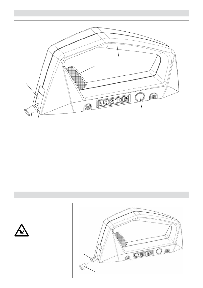
Gerätebeschreibung
6
32
Vorbereitung
1. Handgri
2. Schutzkappe
3. Fugenklinge
4
4. Einstellrad Fugentiefe
5. Ersatz-Schutzkappe
6. Klingenhalter
1
5
Schutzkappe (2) vorsichtig
entfernen.
ACHTUNG!
Die Fugenklinge (3) nicht berühren. Dies kann zu Verletzungen führen.
4
3
2
Page 5

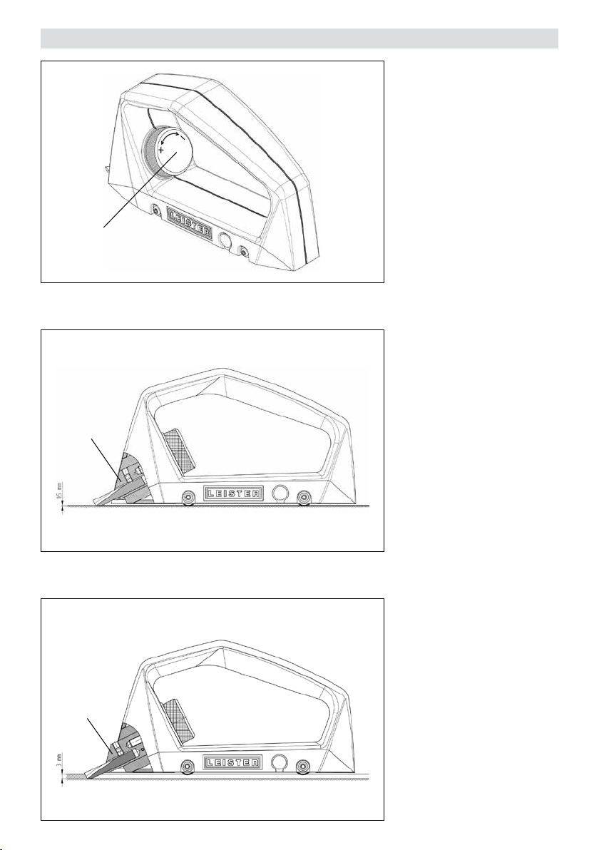
Einstellung Fugentiefe
4
6
Die Fugentiefe ist auf das zu
schweissende Material abzustimmen.
Drehen des Einstellrades (4) im
Gegenuhrzeigersinn ergibt eine
tiefere Fuge (+), Drehen des Ein-
stellrades (4) im Uhrzeigersinn
ergibt eine weniger tiefe Fuge
(-). Eine Umdrehung ergibt eine
Tiefen änderung von ca. 0,35 mm.
Ist der Klingenhalter (6) bündig
mit dem Gehäuse, erreicht die
Klinge eine Schnitt-Tiefe von ca.
0,5mm.
Ist der Klingenhalter (6) ganz
ausgefahren und am Anschlag,
erreicht die Klinge eine maximale
Schnitt-Tiefe von ca. 3,0 mm.
6
5
Page 6

Anwendung
Das Gerät wird mit Hilfe der integrierten Führungsrollen in der bereits geschnittenen Fuge geführt.
Ausführen sauberer Fugen bis
zum Wandabschluss.
Genaues Arbeiten dank Rollenführung und verstellbarer Fugentiefe.
6
Page 7

Wartung
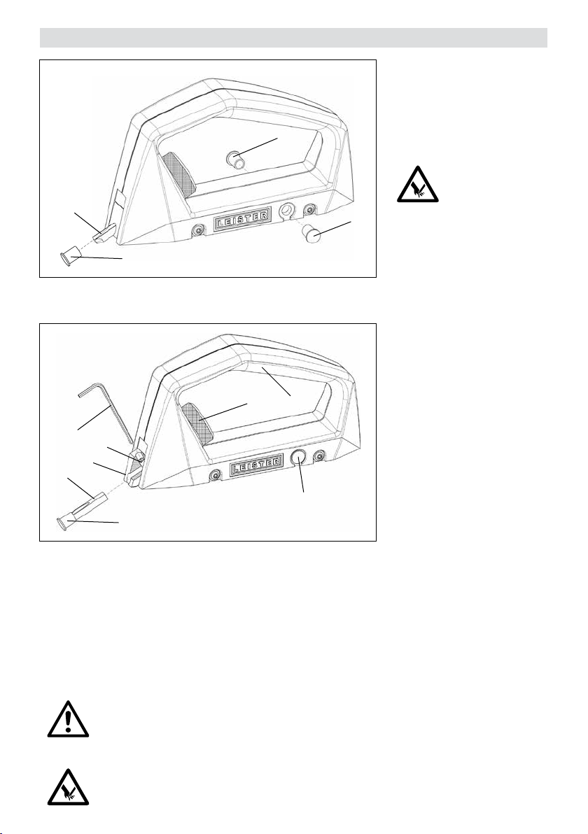
Eine verloren gegangene oder
stark abgenutzte Schutzkap-
pe(2) muss mit einer der beiden
Ersatz-Schutzkappen (5) ersetzt
5
werden.
Die Schutzkappen sind auch als
Ersatzteil erhältlich.
3
2
8
7
6
3
2
1. Handgri
2. Schutzkappe
3. Fugenklinge
4. Einstellrad Fugentiefe
5
4
1
5
5. Ersatz-Schutzkappe
6. Klingenhalter
7. Klemmschraube
8. 2 mm-Sechskant-Stiftschlüssel
ACHTUNG!
Bei Nichtgebrauch muss die Fugenklinge (3) wegen Verletzungs-
gefahr immer mit der Schutzkappe (2) gesichert werden.
Um die Klinge zu ersetzen, muss
der Klingenhalter (6) bis zum Anschlag herausgefahren werden.
Dazu muss das Einstellrad (4) im
Gegenuhrzeigersinn (+) gedreht
werden. Diese Einstellung legt die
Klemmschraube (7) frei. Dann
Klemmschraube (7) ¼-Umdre-
hung lösen und Fugenklinge (3)
herausnehmen. Neue Fugenklin-
ge (3) einsetzen, flachen Anschli
bündig zur Schraubenachse ausrichten und mit Klemmschrau-
be (7) festschrauben.
ACHTUNG!
Damit eine präzise, qualitativ erstklassige Fuge gewährleistet werden kann, muss die Fugenklinge (3)
rechtzeitig ersetzt werden. Dies vermindert auch die von einer stumpfen Fugenklinge (3) ausgehende
Verletzungsgefahr.
ACHTUNG!
Der Handfugenhobel GROOVY darf nur mit der im Lieferumfang enthaltenen Fugenklinge eingesetzt
werden.
ACHTUNG!
Beim Hantieren mit der Fugenklinge (3) muss die Schutzkappe (2) aufgesteckt sein.
7
Page 8

Service und Reparatur
• Reparaturen sind ausschliesslich von autorisierten Leister Service-Stellen ausführen zu lassen. Diese gewährleisten einen fachgerechten und zuverlässigen Reparatur-Service mit Original-Ersatzteilen.
Gewährleistung
• Für dieses Gerät gelten die vom direkten Vertriebspartner/Verkäufer gewährten Garantie- oder Gewährleistungsrechte ab Kaufdatum. Bei einem Garantie- oder Gewährleistungsanspruch (Nachweis durch Rechnung oder
Lieferschein) werden Herstellungs- oder Verarbeitungsfehler vom Vertriebspartner durch Ersatzlieferung oder
Reparatur beseitigt.
• Weitere Garantie- oder Gewährleistungsansprüche werden im Rahmen des zwingenden Rechts ausgeschlossen.
• Schäden, die auf natürliche Abnutzung, Überlastung oder unsachgemässe Behandlung zurückzuführen sind,
werden von der Gewährleistung ausgeschlossen.
• Keine Garantie- oder Gewährleistungsansprüche bestehen bei Geräten, die vom Käufer umgebaut oder verändert
wurden.
8
Page 9

Operating manual (Translation of the original operating instructions)
Read the operating manual carefully before commissioning
and keep it on hand for later consultation.
Grooving tool GROOVY
Application
• Groove preparation without milling
• Groove gouging up to connecting walls
• Clean transition from machine-milled groove to the closure
• Ideal for surfaces that are small and dicult of access
• Precise working thanks to roller guide and adjustable groove depth
Warning
The GROOVY gouging tool may be used only with the groove blade included in the scope
of delivery.
GB
Caution
Device is not permitted to be operated unsupervised.
Device may be used only by trained specialists or under their supervision.
Children are not permitted to operate the equipment under any circumstances.
Do not touch the groove blade of the GROOVY gouging tool. Doing so could lead
to injuries.
Protect the GROOVY gouging tool against dirt and moisture.
Technical data
Groove width 3.5 mm (0.14 inch) U-shape
Groove depth max. 3 mm
Material PVC and Linoleum
We reserve the right to make technical changes
9
Page 10

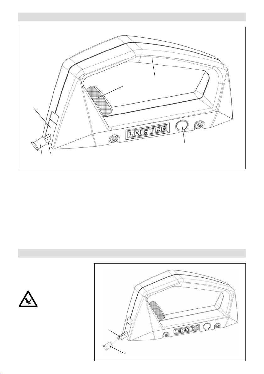
Device description
6
Preparation
32
1. Handle
2. Protective cap
3. Groove blade
4
1
4. Adjustment wheel, groove depth
5. Replacement protective cap
6. Blade holder
5
Carefully remove the protective cap (2).
CAUTION!
Do not touch the groove blade
(3). Doing so could lead to inju-
ries.
10
3
2
Page 11

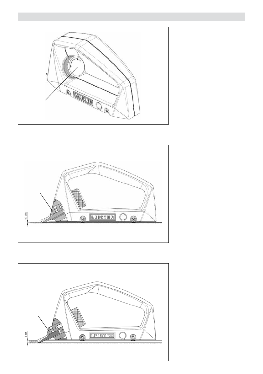
Adjustment, groove depth
4
6
The groove depth is to be tailored to the material to be welded.
Rotating the adjustment wheel
(4) counterclockwise yields a
deeper groove (+), rotating the
adjustment wheel (4) clockwise
yields a groove of lesser depth
(-). Each revolution results in a
change of depth of around 0.35
mm.
If the blade holder (6) is flush
with the housing, then the blade
will achieve a cutting depth of
around 0.5mm.
If the blade holder (6) is completely extended, then the blade
will achieve a maximum cutting
depth of around 3.0mm.
6
11
Page 12

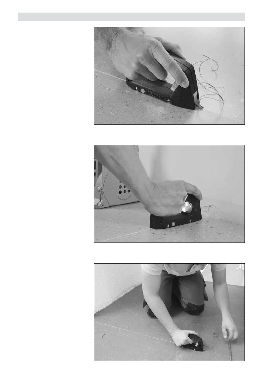
Application
The device is guided along the
groove that has already been cut
with the help of the integrated
guide rollers.
Executing clean grooves up to
connecting walls.
Precise working thanks to roller guide and adjustable groove
depth.
12
Page 13

Maintenance
A protective cap (2) that has
been lost or which exhibits great
wear must be replaced with one
of the two replacement protec-
5
tive caps (5).
The replacement caps are also
available as spare parts.
3
2
8
7
6
3
2
1. Handle
2. Protective cap
3. Groove blade
4. Adjustment wheel, groove depth
5
4
1
5
5. Replacement protective cap
6. Blade holder
7. Clamping screw
8. 2 mm hexagon wrench key
CAUTION!
If not used, the groove blade (3)
must always be secured with the
protective cap (2) because of the
danger of injury.
To replace the blade, the blade
holder (6) must be extended out
to the stop. To accomplish this,
the adjustment wheel (4) must
be rotated counterclockwise (+).
This setting exposes the clamp-
ing screw (7). Then loosen the
clamping screw (7) with a ¼
revolution and remove the groove
blade (3). Insert new groove
blade (3), align flat polish sec-
tion flush with the screw axis and
screw tightly with the clamping
screw (7).
CAUTION!
In order to be able to ensure a precise, high-quality joint, the groove blade (3) must be replaced
when it is time to do so. This also reduces the danger of injury arising from a blunt groove blade (3).
CAUTION!
When handling the groove blade (3), the protective cap (2) must be fitted.
13
Page 14

Service and repair
• Repairs shall be assigned exclusively to authorized Leister Service points. These guarantee a professional and
reliable repair service with original spare parts in accordance with circuit diagrams and spare parts lists.
Warranty
• For this tool, the guarantee or warranty rights granted by the relevant distributor/seller shall apply. In case of
guarantee or warranty claims any manufacturing or workmanship defects will either be repaired or replaced by
the distributor at its discretion. Warranty or guarantee rights have to be verified by an invoice or a delivery document. Heating elements shall be excluded from warranty or guarantee.
• Additional guarantee or warranty claims shall be excluded, subject to mandatory provisions of law.
• Warranty or guarantee shall not apply to defects caused by normal wear and tear, overload or improper handling.
• Warranty or guarantee claims will be rejected for tools that have been altered or changed by the purchaser.
14
Page 15

Istruzioni per l’uso (Traduzione delle istruzioni per l’uso originali)
Prima della messa in servizio leggere attentamente le presenti istruzioni per l’uso
e conservarle per una futura consultazione.
Sgorbia per fughe GROOVY
Applicazione
• Preparazione delle fughe senza fresatura
• Sgorbiatura fino alla terminazione della parete
• Transizione in completa pulizia dalla fuga eseguita con la fresatrice meccanica alla terminazione della parete
• Ideale per le superfici piccole e di dicile accesso
• Precisione operativa grazie alla guida rullo e alla profondità regolabile della fuga
Avvertenza
La sgorbia per fughe GROOVY deve essere utilizzata esclusivamente con la lama di sgorbiatura fornita in dotazione.
Attenzione
I
L’apparecchio deve essere azionato sotto controllo visivo.
L’impiego dell’apparecchio è consentito esclusivamente a personale qualificato
o sotto il monitoraggio di quest’ultimo. È tassativamente vietato l’impiego da parte
dei bambini.
Non toccare la lama di sgorbiatura della sgorbia per fughe GROOVY. Ciò potrebbe
provocare ferite.
La sgorbia per fughe GROOVY deve essere protetta da sporcizia e umidità.
Specifiche tecniche
Larghezza fuga 3,5 mm (0,14 pollici), a forma di U
Profondità fuga max. 3 mm
Materiali PVC e linoleum
Modifiche tecniche riservate
15
Page 16

Descrizione dell’apparecchio
6
32
1. Impugnatura
2. Cappuccio protettivo
3. Lama di sgorbiatura
Operazioni preliminari
4
4. Ghiera di regolazione profondità fuga
5. Cappuccio protettivo sostitutivo
6. Portalama
1
5
Rimuovere con attenzione
il cappuccio protettivo (2).
ATTENZIONE!
Non toccare la lama di sgorbiatura (3). Ciò potrebbe provocare
ferite.
16
3
2
Page 17
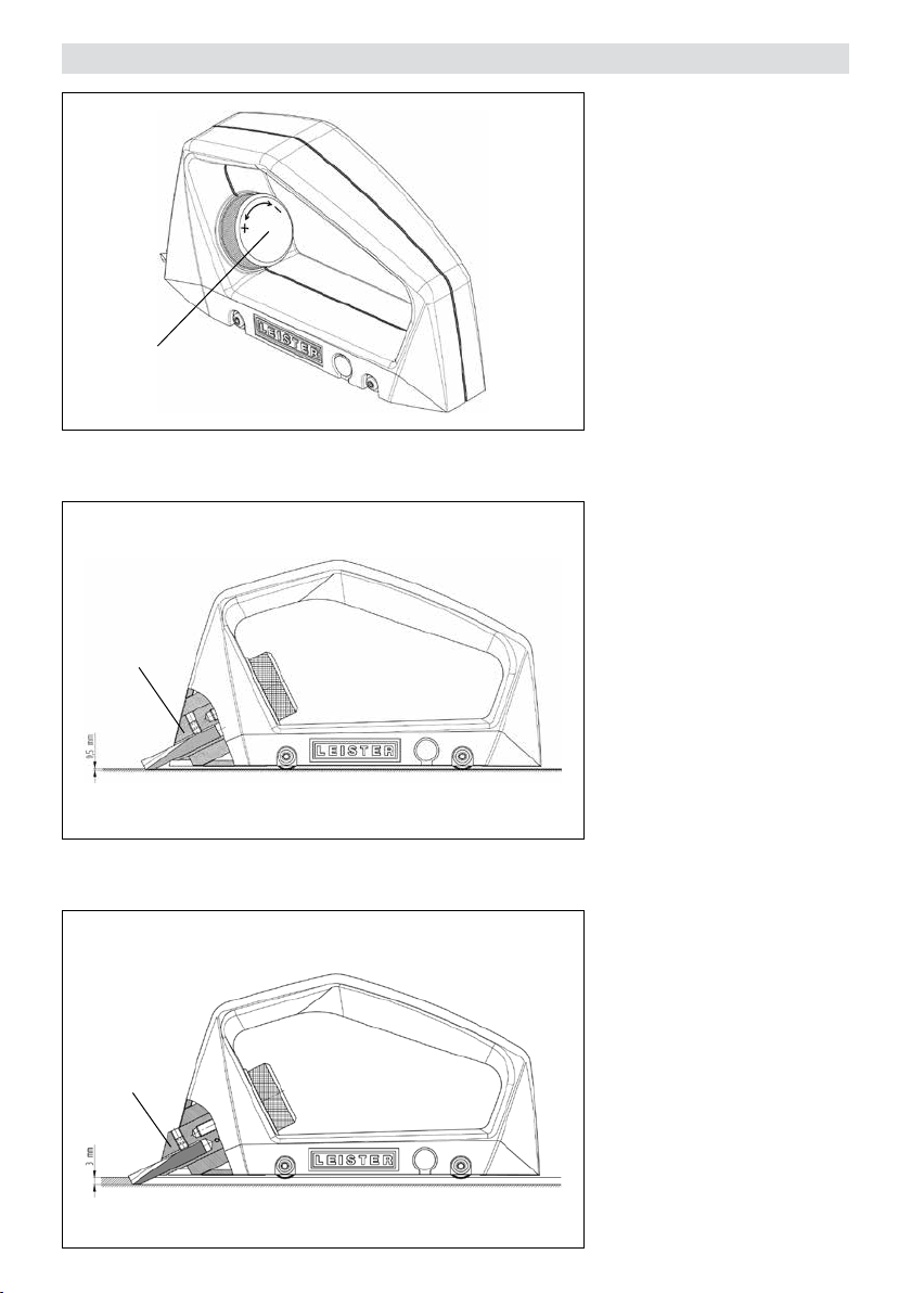
Regolazione della profondità della fuga
4
6
La profondità della fuga deve
essere dimensionata in base al
materiale da saldare.
Se la ghiera di regolazione (4)
è ruotata in senso antiorario, la
fuga risulterà più profonda (+);
se la ghiera di regolazione (4)
è ruotata in senso orario, la fuga
risulterà meno profonda (-). Una
rotazione completa produce una
variazione di profondità pari a circa 0,35mm.
Se il portalama (6) è in linea con
l’alloggiamento, la lama raggiunge una profondità di taglio di circa
0,5mm.
Se il portalama (6) è completamente estratto e in battuta, la
lama raggiunge una profondità di
taglio di circa 3,0mm.
6
17
Page 18
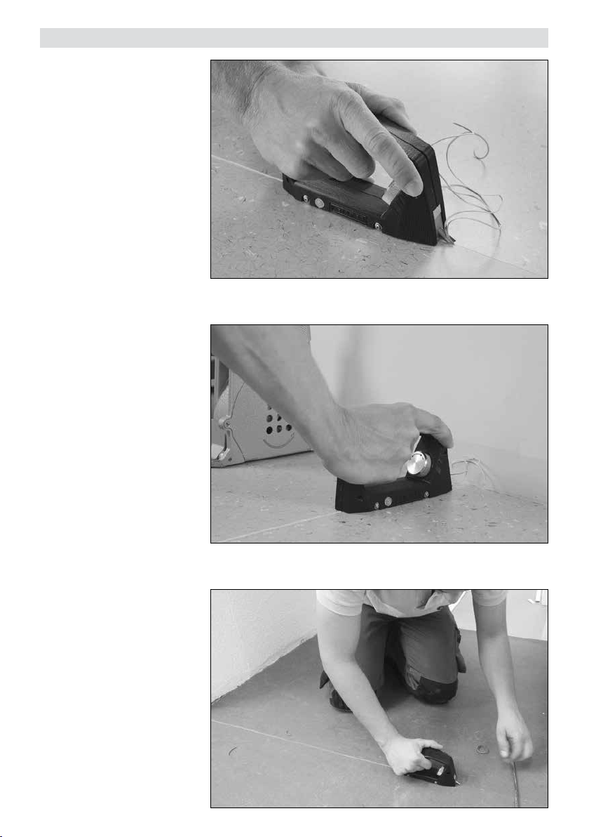
Applicazione
L’apparecchio viene guidato nella
fuga già realizzata mediante gli
appositi rulli di guida integrati.
Esecuzione pulita delle fughe fino
alla terminazione della parete.
Precisione operativa grazie alla
guida rullo e alla profondità regolabile della fuga.
18
Page 19
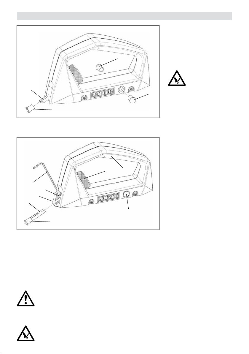
Manutenzione
I cappucci protettivi(2) smar-
riti o molto usurati devono essere
sostituiti con uno dei due cap-
pucci protettivi sostitutivi (5).
5
È possibile ordinare altri cappucci protettivi come parti di
ricambio.
3
2
8
7
6
3
2
1. Impugnatura
2. Cappuccio protettivo
3. Lama di sgorbiatura
4. Ghiera di regolazione
profondità fuga
4
1
5
5. Cappuccio protettivo sostitutivo
6. Portalama
7. Vite di fermo
8. Chiave esagonale da 2mm
5
ATTENZIONE!
Per prevenire eventuali lesioni, quando la lama di sgorbiatura (3) non è
in uso, deve essere sempre coperta
con il cappuccio protettivo (2).
Per sostituire la lama, il portala-
ma (6) deve essere estratto fino
alla battuta. A tale scopo, ruotare
la ghiera di regolazione (4) in
senso antiorario (+). Questa impostazione consente di svincolare
la vite di fermo (7). Allentare
quindi la vite di fermo (7) di ¼
di giro ed estrarre la lama di
sgorbiatura (3). Inserire la nuova
lama di sgorbiatura (3), allinea-
re la superficie piana alata con
l’asse della vite e serrare agendo
sulla vite di fermo (7).
ATTENZIONE!
Per ottenere fughe perfette e di qualità superiore, la lama di sgorbiatura (3) deve essere sostituita
regolarmente. Una puntuale sostituzione riduce anche il rischio di lesioni procurato da lame di sgor-
biatura (3) smussate.
ATTENZIONE!
Durante la manipolazione della lama di sgorbiatura (3) il cappuccio protettivo (2) deve essere
sempre applicato.
19
Page 20

Assistenza e riparazioni
• Le riparazioni devono essere eseguite esclusivamente dai centri di assistenza autorizzati da Leister. Questi
ultimi assicurano riparazioni sicure e adabili, con parti di ricambio originali come da schemi elettrici ed elenchi
parti di ricambio.
Garanzia legale
• A questo prodotto si applicano i diritti previsti per la garanzia concessi dal partner di distribuzione/rivenditore diretto, a partire dalla data di acquisto. In caso di ricorso alla garanzia (fanno fede la fattura o la bolla di consegna),
sono previste la fornitura sostitutiva o la riparazione di difetti di fabbricazione o di lavorazione a cura del partner
di distribuzione. La garanzia non si applica agli elementi riscaldanti.
• È esclusa qualsiasi ulteriore garanzia non espressamente prevista dalle vigenti norme di diritto cogente.
• Sono esclusi dalla garanzia i danni riconducibili alla naturale usura, al sovraccarico o alla scorretta manipolazione.
• Il ricorso alla garanzia decade per gli apparecchi sottoposti a modifiche o alterazioni da parte dell’acquirente.
20
Page 21
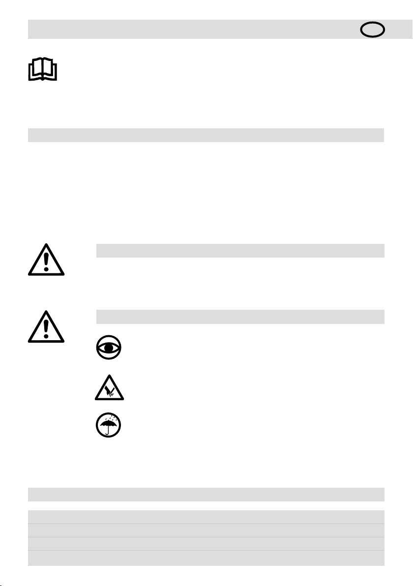
Notice d’utilisation (traduction de la notice d’utilisation d’origine)
Lire attentivement la présente notice d’utilisation avant la mise en service
et la conserver pour consultation ultérieure.
Gougeur à main GROOVY
Application
• Préparation des joints sans fraise
• Rognage des joints jusqu’au raccord avec le mur
• Transition impeccable entre le joint fraisé mécaniquement et le raccord
• Idéal pour les surfaces de dimensions réduites et dicilement accessibles
• Travail précis grâce au guidage par rouleaux et à la profondeur de joint réglable
Avertissement
Le gougeur à main GROOVY ne doit être utilisé qu’avec la lame coupe-joint fournie à la
livraison.
F
Prudence
L’appareil ne doit pas être utilisé sans surveillance.
L’appareil doit uniquement être utilisé par des spécialistes qualifiés ou sous leur
surveillance. L’utilisation de l’appareil par des enfants est absolument interdite.
Ne pas toucher la lame coupe-joint du gougeur à main GROOVY. Risque de blessure.
Protéger le gougeur à main GROOVY de la saleté et de l’humidité.
Caractéristiques techniques
Largeur de joint 3,5mm (0,14pouce), en forme deU
Profondeur de joint max. 3mm
Matériau PVC et linoléum
Sous réserve de modifications techniques
21
Page 22
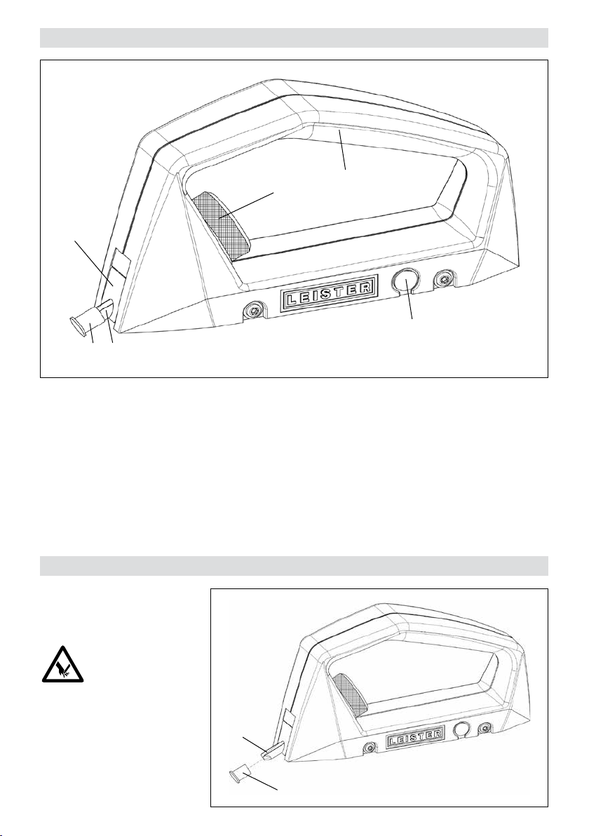
Description de l’appareil
6
1. Poignée
2. Capuchon de protection
3. Lame coupe-joint
Préparation
4
32
4. Molette de réglage de la profondeur de joint
5. Capuchon de protection de rechange
6. Support de lame
1
5
Retirer avec précaution le capuchon de protection(2).
ATTENTION!
Ne pas toucher la lame coupe-joint(3). Risque de blessure.
22
3
2
Page 23
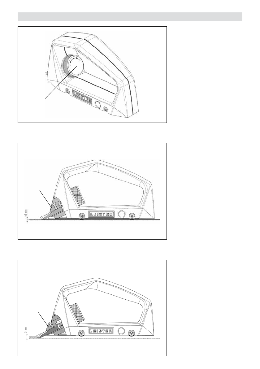
Réglage de la profondeur de joint
4
6
La profondeur de joint doit être
adaptée au matériau à souder.
Tourner la molette de réglage (4) dans le sens inverse des
aiguilles d’une montre pour obtenir un joint plus profond(+). Tourner la molette de réglage (4)
dans le sens des aiguilles d’une
montre pour réduire la profondeur
du joint(-). Un tour correspond à
une modification de la profondeur
de 0,35mm environ.
Si le support de lame(6) aeure
le boîtier, la lame atteint une profondeur de découpe de 0,5 mm
environ.
Si le support de lame (6) est
entièrement sorti et en butée, la
lame atteint une profondeur de
découpe maximale de 3,0 mm
environ.
6
23
Page 24
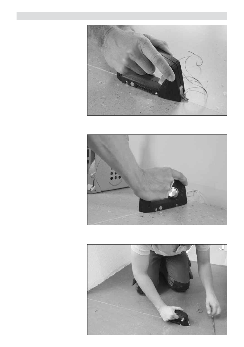
Application
L’appareil est guidé dans le joint
déjà découpé à l’aide des rouleaux de guidage intégrés.
Les joints sont réalisés impeccablement jusqu’au raccord avec le
mur.
Le travail est précis grâce au guidage par rouleaux et à la profondeur de joint réglable.
24
Page 25
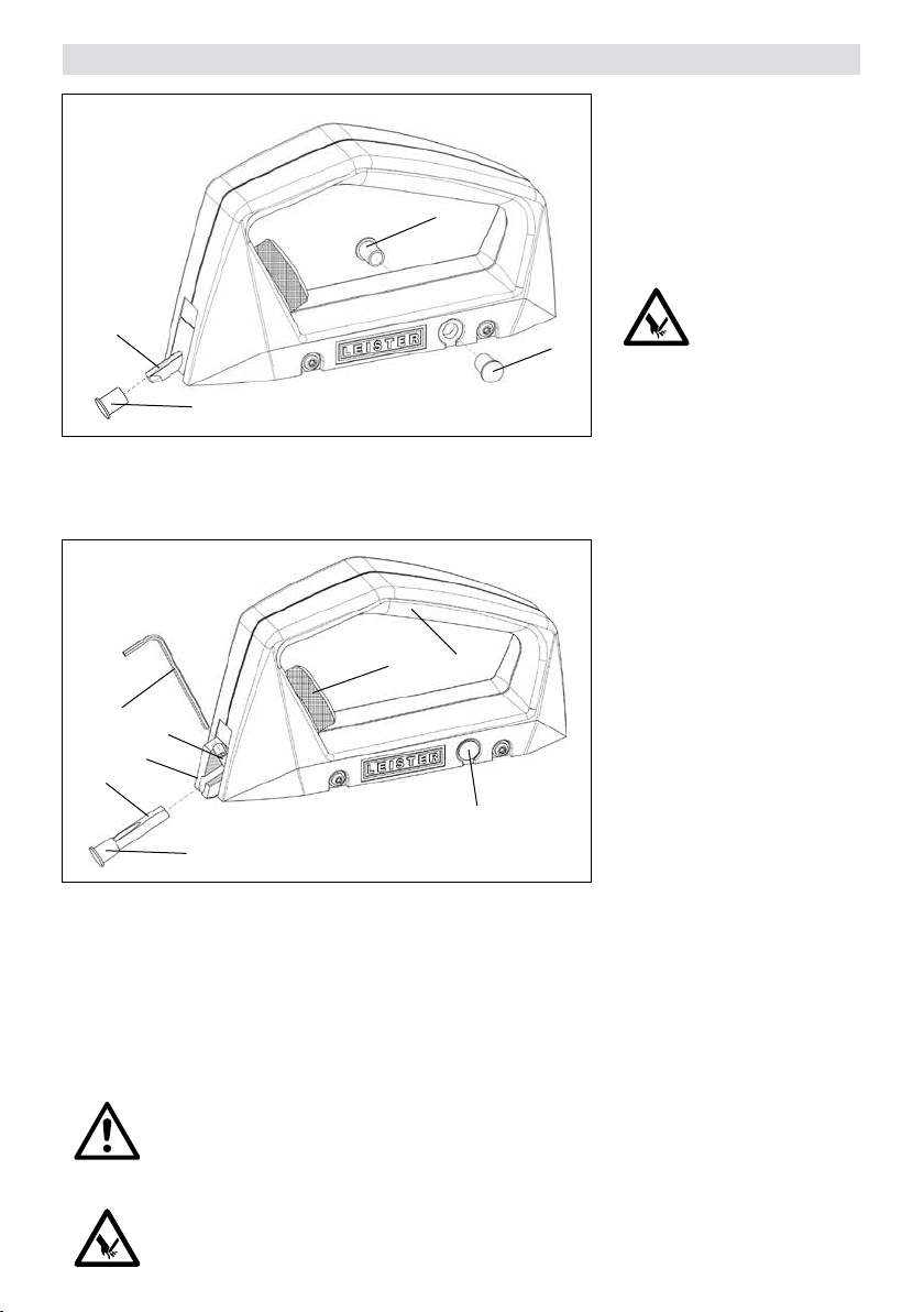
Entretien
3
2
8
7
6
3
2
1. Poignée
2. Capuchon de protection
3. Lame coupe-joint
4. Molette de réglage de
la profondeur de joint
5
4
1
5
5. Capuchon de protection de
rechange
6. Support de lame
7. Vis de blocage
8. Clé Allen 2mm
Si le capuchon de protection(2)
est perdu ou fortement usé, il doit
être remplacé par l’un des deux
capuchons de protection de
rechange(5).
Les capuchons de protection sont
également disponibles en tant que
pièces de rechange.
5
ATTENTION!
Si l’appareil n’est pas utilisé, la
lame coupe-joint (3) doit toujours être protégée avec le capuchon de protection (2), en
raison du risque de blessure.
Pour remplacer la lame, le sup-
port de lame (6) doit être sorti
jusqu’en butée. Pour ce faire, la
molette de réglage (4) doit être
tournée dans le sens inverse
des aiguilles d’une montre (+).
Ce réglage libère la vis de blo-
cage (7). Desserrer ensuite la
vis de blocage(7) d’¼ de tour
et retirer la lame coupe-joint(3).
Insérer une lame coupe-joint(3)
neuve, aligner la partie polie plate
de sorte qu’elle aeure l’axe de
la vis et serrer fermement avec la
vis de blocage (7).
ATTENTION!
Pour garantir des joints précis et d’excellente qualité, la lame coupe-joint (3) doit être remplacée en
temps voulu. Cela réduit également le risque de blessure lié à l’utilisation d’une lame coupe-joint (3)
émoussée.
ATTENTION!
Lors de la manipulation de la lame coupe-joint(3), le capuchon de protection(2) doit être en place.
25
Page 26

Service et réparations
• Les réparations doivent uniquement être eectuées par des centres de service Leister agréés. Ils garantissent
un service de réparation professionnel et fiable, avec des pièces de rechange d’origine conformes aux schémas
de connexion et listes de pièces de rechange.
Garantie
• Les droits de garantie fabricant et de garantie légale accordés par le partenaire commercial ou vendeur direct
s’appliquent à cet appareil à compter de la date d’achat. En cas de recours à la garantie (justificatif par la facture
ou le bordereau de livraison), les défauts de fabrication ou d’usinage seront supprimés par le partenaire commercial qui procédera à une fourniture en remplacement ou à une réparation. Les éléments chauants sont exclus
de la garantie.
• Toute autre prétention à la garantie fabricant ou à la garantie légale dans le cadre du droit en vigueur est exclue.
• Les dommages résultant d’une usure naturelle, d’une surcharge ou d’un traitement non conforme sont exclus de
la garantie.
• Aucun droit à revendication n’est accordé pour les appareils qui auront été transformés ou modifiés par l’acheteur.
26
Page 27
Instrucciones de servicio (Traducción de las instrucciones de servicio originales)
Leer las instrucciones de servicio con atención antes de la puesta en servicio
y conservarlas para futuras consultas.
Cepillo acanalador manual GROOVY
Aplicación
• Preparación de juntas sin fresas
• Cepillo acanalador hasta la terminación de pared
• Desplazamiento limpio de las juntas fresadas mecánicamente hasta la terminación
• Ideal para superficies reducidas y de difícil acceso
• Trabajo preciso gracias a los rodillos guía y a la profundidad ajustable de las juntas
Advertencia
El cepillo acanalador manual GROOVY solo puede utilizarse con la cuchilla contenida en el
volumen de suministro.
E
Precaución
El dispositivo debe operarse con supervisión.
El equipo solo lo puede manejar personal especializado formado o personas
que estén bajo su supervisión. Los niños no están autorizados a emplear el equipo
bajo ningún concepto.
No toque la cuchilla del cepillo acanalador GROOVY. Podría provocar lesiones.
Proteger el cepillo acanalador GROOVY de la suciedad y la humedad.
Datos técnicos
Ancho de las juntas 3,5 mm (0,14 pulgadas) Forma de U
Profundidad de las juntas máx. 3 mm
Material PVC y linóleo
Sujeto a modificaciones técnicas
27
Page 28
Descripción del equipo
6
32
1. Mango
2. Casquete protector
3. Cuchilla
Preparación
4
4. Rueda de ajuste de la profundidad de las juntas
5. Casquete protector de repuesto
6. Soporte de la cuchilla
1
5
Quite el casquete protector (2)
con cuidado.
ATENCIÓN
No toque la cuchilla (3). Podría
provocar lesiones.
28
3
2
Page 29
Ajuste de la profundidad de las juntas
4
6
La profundidad de las juntas
debe coincidir con el material
a soldar.
Girar la rueda de ajuste (4) en
sentido antihorario proporciona
una junta más profunda (+), girar
la rueda de ajuste (4) en sentido
horario proporciona una junta menos profunda (-). Cada vuelta proporciona una modificación de la
profundidad de aprox. 0,35 mm.
Si el soporte de la cuchilla (6)
está al ras de la carcasa, la cuchilla realizará un corte de aprox.
0,5mm de profundidad.
Si el soporte de la cuchilla (6)
está completamente extendido
y al tope, la cuchilla realizará un
corte de máximo 3,0 mm de profundidad.
6
29
Page 30
Aplicación
El equipo se llevará hasta la junta
ya cortada con ayuda de los rodillos guía integrados.
Sellado de juntas limpias hasta la
separación de pared.
Trabajo preciso gracias a los rodillos guía y a la profundidad ajustable de las juntas.
30
Page 31
Mantenimiento
Si el casquete protector (2) se
ha perdido o está muy desgastado, hay que cambiarlo con uno de
los dos casquetes protectores
5
de repuesto (5).
Puede obtener casquetes protectores como piezas de repuesto.
3
2
8
7
6
3
2
1. Mango
2. Casquete protector
3. Cuchilla
4. Rueda de ajuste de la
profundidad de las juntas
5
4
1
5
5. Casquete protector de repuesto
6. Soporte de la cuchilla
7. Tornillo de fijación
8. Llave hexagonal de 2 mm
ATENCIÓN
Cuando no se utilice, hay que proteger la cuchilla (3) para evitar
lesiones utilizando siempre el
casquete protector (2).
Para sustituir la cuchilla, hay que
sacar el soporte de la cuchilla
(6) hasta el tope. Para ello, hay
que girar la rueda de ajuste (4)
en sentido antihorario (+). Este
ajuste deja al descubierto el tor-
nillo de fijación (7). Después,
aflojar el tornillo de fijación (7)
¼ de vuelta y sacar la cuchilla
(3). Colocar la nueva cuchilla (3),
alinear la parte afilada al ras del
eje helicoidal y atornillarlo con el
tornillo de fijación (7).
ATENCIÓN
Para garantizar una junta precisa y de primera calidad, hay que sustituir a tiempo la cuchilla(3). Esto
reduce también los riesgos de lesión que podría provocar una cuchilla (3) desafilada.
ATENCIÓN
Al trabajar con la cuchilla (3), el casquete protector (2) debe estar quitado.
31
Page 32

Asistencia y reparaciones
• Solo el servicio técnico de Leister está autorizado a realizar reparaciones en el dispositivo. Este garantiza un
servicio de reparación profesional y de confianza con piezas de repuesto originales conformes a los esquemas
de conexiones y a las listas de piezas de repuesto.
Garantía
• Para este dispositivo tienen validez los derechos de garantía comercial o legal concedidos por el socio de distribución directo/el vendedor a partir de la fecha de compra. En caso de que exista derecho de garantía comercial
o legal (certificación mediante factura o albarán de entrega), el socio de distribución subsanará los daños de
fabricación o tratamiento con una entrega de reposición o una reparación. Las resistencias están excluidas de la
garantía.
• Cualquier otro derecho de garantía comercial o legal se excluirá en el marco del derecho imperativo.
• Los daños provocados por el desgaste natural del equipo, sobrecarga o manejos inadecuados quedan excluidos
de la garantía.
• No habrá ningún derecho de garantía comercial o legal en el caso de los dispositivos que hayan sido alterados o
modificados por el comprador.
32
Page 33
Kullanım Kılavuzu (Orijinal Kullanım Talimatlarının Çevirisidir)
İşletime almadan önce kullanım kılavuzunu dikkatli bir şekilde
okuyun ve ileride başvurmak için saklayın.
Derz oyma aleti GROOVY
Kullanım
• Frezesiz derz hazırlama
• Duvar bitişine kadar derz oyma
• Mekanik frezelenmiş derzin bitişe kadar temiz geçişi
• Küçük ve zor erişilen alanlar için ideal
• Makaralı kılavuz ve ayarlanabilir derz derinliği sayesinde hassas çalışma
İkaz
Derz oyma aleti GROOVY sadece teslimat kapsamında bulunan derz bıçağı ile kullanılabilir.
TR
Uyarı
Cihaz gözetimli olarak kullanılmalıdır.
Cihaz sadece eğitim almış uzmanlar tarafından veya onların gözetimi altında
kullanılmalıdır. Cihazın çocuklar tarafından kullanılması tamamen yasaktır.
GROOVY derz oyma aletinin derz bıçaklarına dokunmayın. Bu, yaralanmalara yol
açabilir.
GROOVY derz oyma aletini kir ve neme karşı koruyun.
Teknik veriler
Derz genişliği 3.5 mm (0.14 inç) U biçimi
Derz derinliği maks. 3 mm
Malzeme PVC ve linolyum
Teknik değişiklik yapma hakkı mahfuzdur
33
Page 34
Cihaz tanımı
6
Hazırlık
32
1. Tutamak
2. Koruyucu başlık
3. Derz bıçağı
4
1
4. Derz derinliği ayar çarkı
5. Yedek koruyucu başlık
6. Bıçak tutucu
5
Koruyucu başlığı (2) dikkatlice
çıkarın.
DİKKAT!
Derz bıçağına (3) dokunmayın.
Bu, yaralanmalara yol açabilir.
34
3
2
Page 35
Derz derinliği ayarı
4
6
Derz derinliği, kaynak edilecek
malzemeye uyarlanmalıdır.
Ayar çarkının (4) saat yönünün
tersine döndürülmesi daha derin
bir derz (+), ayar çarkının (4)
saat yönünde döndürülmesi daha
az derinlikte bir derz (-) oluşturur.
Bir tur yakl. 0,35 mm derinlik değişimi sağlar.
Bıçak tutucu (6) gövdeyle aynı
hizadaysa bıçak yakl. 0,5mm kesim derinliğine ulaşır.
Bıçak tutucu (6) tamamen dışarı
çıkmış ve dayanak noktasında gelmişse bıçak yakl. 3,0mm maksimum kesim derinliğine ulaşır.
6
35
Page 36
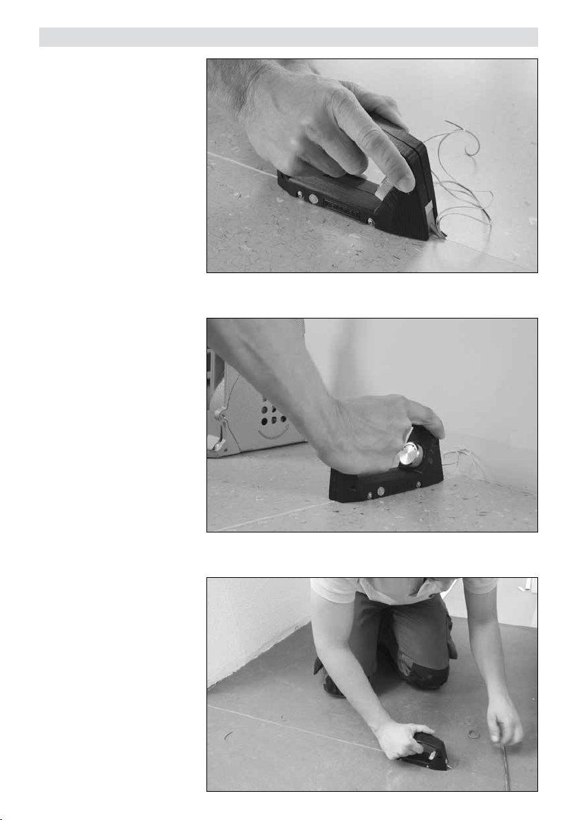
Kullanım
Bu alet, kesilmiş derz içinde entegre kılavuz makaralar üzerinden
yürütülür.
Duvar bağlantısına kadar temiz
derz oluşturma.
Makaralı kılavuz ve ayarlanabilir
derz derinliği sayesinde hassas
çalışma.
36
Page 37
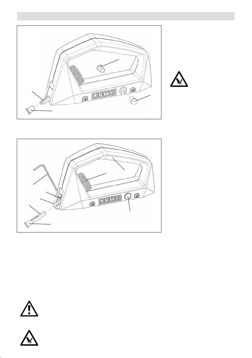
Bakım
Koruyucu başlığın (2) kaybol-
ması veya güçlü şekilde aşınmış
olması durumunda iki yedek ko-
ruyucu başlıktan (5) birinin de-
5
ğiştirilmesi gerekir.
Koruyucu başlıklar yedek parça
olarak da temin edilebilir.
3
2
8
7
6
3
2
1. Tutamak
2. Koruyucu başlık
3. Derz bıçağı
4. Derz derinliği ayar çarkı
4
1
5
5. Yedek koruyucu başlık
6. Bıçak tutucu
7. Sıkma vidası
8. 2 mm altıgen anahtar
5
DİKKAT!
Kullanılmadığı durumda derz
bıçağının (3) yaralanma tehli-
kesi nedeniyle daima koruyucu
başlıkla (2) emniyete alınmalıdır.
Bıçağı değiştirmek için bıçak tutucunun (6) dayanak noktasına
kadar dışarı çıkarılması gerekir.
Bunun için ayar çarkının (4) saat
yönünün tersi yönde (+) döndürülmesi gerekir. Bu ayar, sıkma vi-
dasını (7) boşa çıkarır. Ardından
sıkma vidasını (7) ¼ tur çözün
ve derz bıçağını (3) dışarı çıkarın.
Yeni derz bıçağını (3) takın, yassı
sırtı vida eksenine hemyüz olarak
hizalayın ve sıkma vidasıyla (7)
iyice sıkın.
DİKKAT!
Hassas, birinci kalite bir derz sağlanabilmesi için derz bıçağının (3) zamanında değiştirilmesi gerekir.
Bu ayrıca kör bir derz bıçağından (3) kaynaklanan yaralanma tehlikesini de azaltır.
DİKKAT!
Derz bıçağını (3) kullanırken koruyucu başlığın (2) takılı olması gerekir.
37
Page 38

Servis ve Bakım
• Onarımların sadece yetkili Leister servis merkezlerine yaptırılması gerekmektedir. Bu servis merkezleri size
uzman ve güvenilir bir onarım hizmeti vermeyi ve devre şemaları ile yedek parça listelerine uygun orijinal yedek
parça sağlamayı garanti ederler.
Garanti
• Bu cihaz için doğrudan satış acentesi/satıcı tarafından sağlanan teminat ve garanti hakları satış tarihinden itibaren geçerlidir. (Sevk irsaliyesi ve faturayla belgelendirilmiş olmak kaydıyla) Teminat veya garanti talebinde üretim
veya işleme hataları distribütör tarafından, cihazı yenisi ile değiştirme veya onarma suretiyle giderilir. Isıtma
elemanları teminat veya garanti kapsamı dışındadır.
• Ek teminat veya garanti talepleri zorunlu kanun kapsamı dışındadır.
• Normal aşınma, aşırı yüklenme veya yanlış kullanım nedeniyle oluşan hasarlar garanti kapsamı dışındadır.
• Üzerinde satın alan tarafından değişiklik veya tadilat yapılmış olan cihazlar teminat veya garanti kapsamı dışındadır.
38
Page 39
Руководство по эксплуатации
(перевод оригинального руководства по эксплуатации)
RUS
Перед вводом в эксплуатацию следует внимательно прочитать данное
руководство по эксплуатации и сохранить его для дальнейшего
использования.
Ручной прибор для расшивки швов GROOVY
Использование
• Подготовка шва без фрезерования
• Расшивка швов вплотную к стене
• Чистый переход от шва, расшитого фрезой, к стене
• Идеально подходит для небольших и трудно доступных поверхностей
• Точность выполнения работ благодаря направляющим роликам и возможности регулирования глубины
расшивки
Предупреждение
Ручной прибор для расшивки швов GROOVY можно использовать только с лезвием,
входящим в комплект поставки.
Внимание
Прибор должен эксплуатироваться под контролем.
Прибор разрешается использовать только квалифицированным
специалистам или под их надзором. Данный прибор категорически
запрещено использовать детям.
Не касаться лезвия ручного прибора для расшивки швов GROOVY. В противном случае существует опасность получения травм.
Обеспечить защиту ручного прибора для расшивки швов GROOVY от грязи
и влаги.
Технические характеристики
Ширина расшивки 3,5мм (0,14дюйма) U-образная форма
Глубина расшивки макс. 3мм
Материал ПВХ и линолеум
Право на внесение технических изменений сохранено
39
Page 40
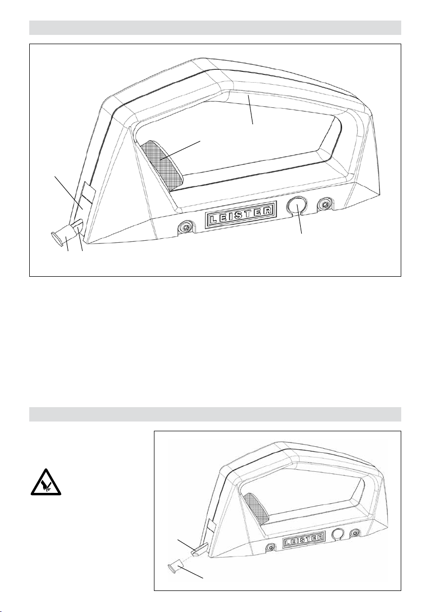
Описание прибора
6
32
1. Рукоятка
2. Защитный колпачок
3. Лезвие
Подготовка
4
4. Установочное колесико для глубины расшивки
5. Запасной защитный колпачок
6. Держатель лезвия
1
5
Защитный колпачок(2) осто-
рожно снять.
ВНИМАНИЕ!
Не касаться лезвия (3). В
противном случае существует
опасность получения травм.
40
3
2
Page 41
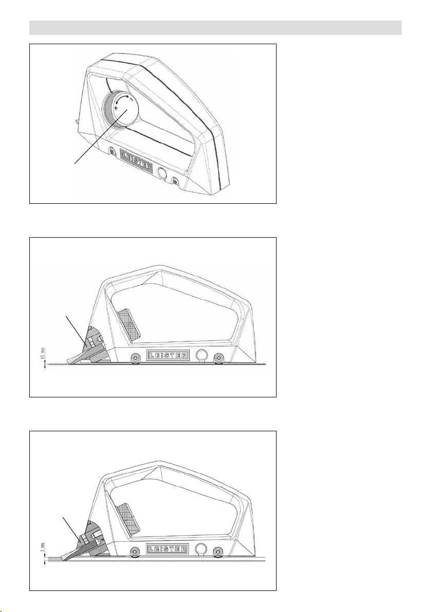
Настройка глубины расшивки
4
6
Глубина расшивки
настраивается в зависимости
от свариваемого материала.
При повороте установочного
колесика (4) против часовой
стрелки глубина шва увеличивается (+), при повороте
установочного колесика (4)
по часовой стрелке глубина
шва уменьшается (-). При полном обороте колесика глубина
изменяется прибл. на 0,35мм.
Если держатель лезвия(6) находится вровень с корпусом, то
глубина шва составляет прибл.
0,5мм.
Если держатель лезвия (6)
выдвинут полностью до упора, то глубина шва достигает
максимального размера прибл.
3,0мм.
6
41
Page 42
Использование
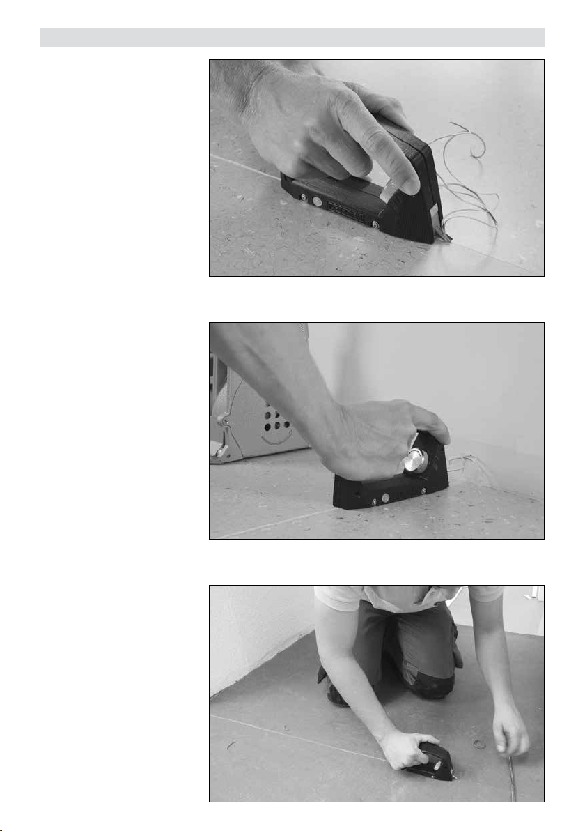
Ход прибора с помощью встроенных направляющих роликов
осуществляется в предварительно сделанном шве.
Расшивка швов вплотную к стене.
Точность выполнения работ
благодаря направляющим роликам и возможности регулирования глубины расшивки.
42
Page 43
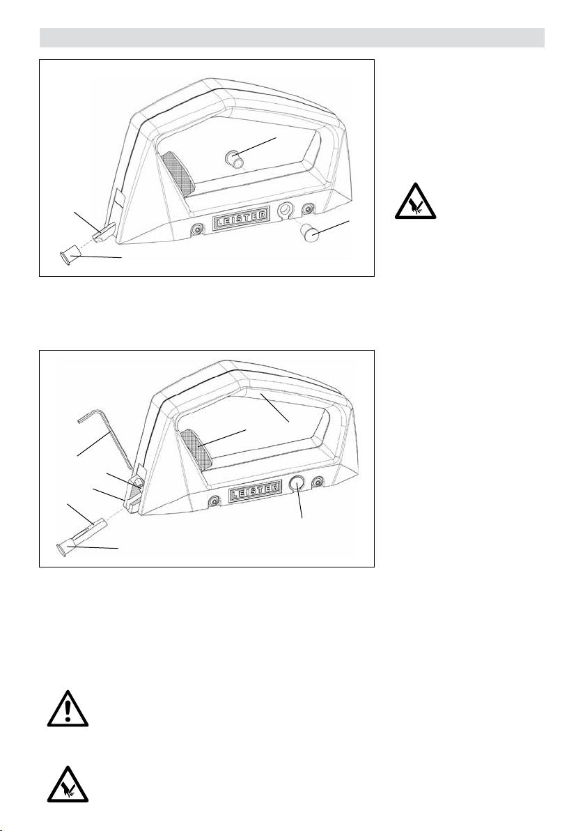
Техническое обслуживание
3
2
8
7
6
3
2
1. Рукоятка
2. Защитный колпачок
3. Лезвие
4. Установочное колесико
для глубины расшивки
Утерянный или сильно изношенный защитный колпа-
чок (2) необходимо заменить
одним из запасных колпач-
5
5
4
1
5
5. Запасной защитный колпачок
6. Держатель лезвия
7. Зажимный винт
8. Торцовый ключ для внутренних
шестигранников 2мм
ков(5).
Защитные колпачки можно
приобрести также в качестве
запасной части.
ВНИМАНИЕ!
В случае неиспользования
прибора лезвие (3) из-за
опасности получения травм
необходимо всегда закрывать
защитным колпачком(2).
Чтобы заменить лезвие, необходимо полностью выдвинуть держатель лезвия (6)
до упора. Для этого следует
повернуть установочное ко-
лесико (4) против часовой
стрелки (+). Такое положение
открывает доступ к зажим-
ному винту (7). Ослабить за-
жимный винт(7) на ¼ оборота
и снять лезвие (3). Вставить
новое лезвие(3), плоский срез
выровнять по оси винта и зафиксировать зажимным вин-
том(7).
ВНИМАНИЕ!
Для обеспечения точной, высококачественной расшивки необходимо своевременно менять
лезвие (3). Это сведет к минимуму опасность травмирования, которая можеть быть вызвана
затуплением лезвия (3) .
ВНИМАНИЕ!
Во время манипуляций с лезвием(3) защитный колпачок(2) должен быть надет.
43
Page 44

Сервисное обслуживание и ремонт
• Поручать проведение ремонтных работ только авторизованным сервисным центрам компании Leister.
Вы можете полагаться на их квалифицированных сотрудников, которые выполнят все необходимые
сервисные работы с использованием оригинальных запасных частей согласно схемам электрических
соединений и спецификациям запасных частей.
Гарантия
• На данное устройство, начиная с даты покупки, распространяются гарантийные обязательства или поручительство прямого дистрибьютора/продавца. При получении претензий по гарантии или поручительству
(с предоставлением счета или квитанции о поставке) производственные дефекты или дефекты обработки устраняются посредством ремонтных работ или замены устройства. Данная гарантия или поручительство не распространяется на нагревательные элементы.
• Другие претензии по гарантии или обязательству исключаются на основании императивных правовых
норм.
• Данная гарантия не распространяется на неполадки, возникшие в результате естественного износа, перегрузки или ненадлежащего использования.
• Гарантия или поручительство теряет свою силу, если покупатель переоборудовал устройство или внес в
него изменения.
44
Page 45
操作说明书
(
操作说明原件的翻译
)
投入运行之前请认真阅读操作说明书
并妥善保存以备继续使用。
开槽机 GROOVY
应用
• 不用铣切工具完成开槽准备工作
• 开槽一直延伸到压边条
• 规整地从机器开槽过渡到压边条
• 用于狭小、不易触及表面的理想工具
• 滚轮导引器和可调开槽深度使得操作更为精确
警告
开槽机 GROOVY 只能结合供货范围内含的开槽刀片使用。
CN
小心
仪器必须在照管下投入使用。
仅可由经培训的专业人员或在其监督下使用本设备。儿童绝对不
可使用。
请勿触碰 GROOVY 开槽机的开槽刀片。这可能导致受伤。
请保护 GROOVY 开槽机不受脏污和潮气侵入。
技术数据
开槽宽度 3.5 mm (0.14 英寸) U 形
开槽深度 最大 3 mm
材料 PVC 和油毡
保留技术更改权
45
Page 46
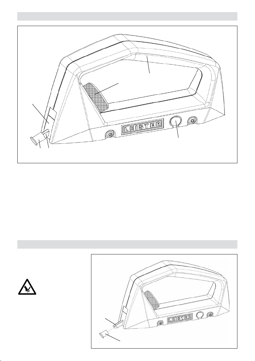
设备说明
6
准备
32
1. 手柄
2. 保护帽
3. 开槽刀片
4
1
4. 开槽深度调节滚轮
5. 备用保护帽
6. 刀片架
5
小心地除下保护帽 (2)。
注意!
请勿触摸开槽刀片 (3)。这
可能导致受伤。
46
3
2
Page 47
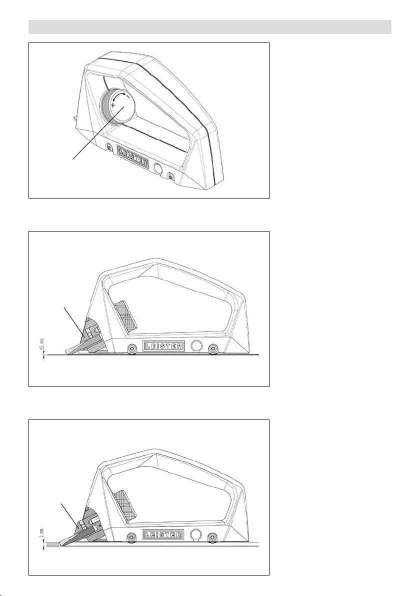
开槽深度的设定
4
6
开槽深度取决于需要焊接
的材料。
逆时针旋转 调节轮 (4) 会增
加开槽深度 (+),顺时针旋
转 调节轮 (4) 则减少开槽深
度 (-)。旋转一周产生的深
度变化约为 0.35 mm。
如果刀片架 (6) 与机身对
其,刀片达到的切割深度
约为 0.5 mm。
如果刀片架 (6) 完全推出并
至止档位,刀片达到的切
割深度约为 3.0 mm。
6
47
Page 48
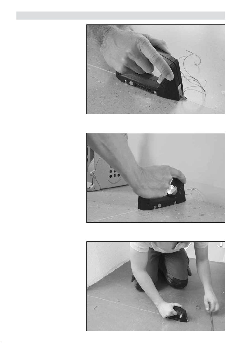
应用
仪器会借助内置的导向滚
轮沿着已切割的开槽线导
引。
制作出规整的开槽,一直
延伸到压边条。
滚轮导引器和可调开槽深
度使得操作更为精确。
48
Page 49
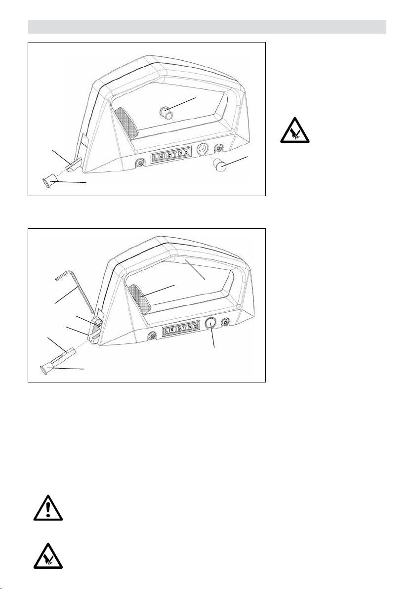
维修保养
丢失或者严重磨损的保护
帽 (2) 必须用两个备用保护
帽 (5) 之一替代。
保护帽可作为备件供应。
5
3
2
8
7
6
3
2
1. 手柄
2. 保护帽
3. 开槽刀片
4. 开槽深度调节滚轮
4
1
5
5. 备用保护帽
6. 刀片架
7. 夹紧螺丝
8. 2 mm 六角平头销钉
5
注意!
不使用时开槽刀片(3) 因伤
害危险必须一直 用保护帽
(2) 保护。
为了更换刀片,必须将刀
片架 (6) 驶出直至止档位。
为此须将调节轮 (4) 逆时针
(+) 旋转。这一设置使得夹
紧螺丝 (7) 露出。然后将夹
紧螺丝 (7) 旋转 ¼ 圈卸下
并取出开槽刀片 (3)。装入
新的开槽刀片 (3),扁平磨
面与螺丝轴对齐并用夹紧
螺丝 (7) 拧紧。
注意!
为了保证精准、高质量一流的开槽工作,必须适时更换开槽刀片 (3) 。这也避免了
因钝化的开槽刀片 (3) 导致的受伤危险。
注意!
操作 开槽刀片 3 时必须套上保护帽 (2) 。
49
Page 50

服务和维修
• 仅可由授权的莱丹服务部门进行维修。这样可确保按照电路图和备件列表使用原装备件提
供专业且可靠的维修服务。
保修
•此设备自购买之日起适用直销代理/销售商提供的担保或保修权利。若因生产或加工问题提
出担保或保修要求(通过账单或供货单证明),此类问题将由经销商通过更换备件或维修
予以排除。加热元件不属于担保或保修范围。
•其他担保或保修要求均依照强制性法规予以排除。
•由正常磨损、过载或不当操作造成的损坏不可享受保修服务。
•若购买者对设备进行改装或更改,则不再享受担保或保修服务。
50
Page 51

Page 52

®
Your authorised Service Centre is:
© Copyright by Leister
Leister Technologies AG
Galileo-Strasse 10
CH-6056 Kaegiswil/Switzerland
Tel. +41 41 662 74 74
Fax +41 41 662 74 16
www.leister.com
[email protected]
BA Handfugenhobel GROOVY / 09.1997 / 08.2019
Art. 153.104
 Loading...