

Page 1
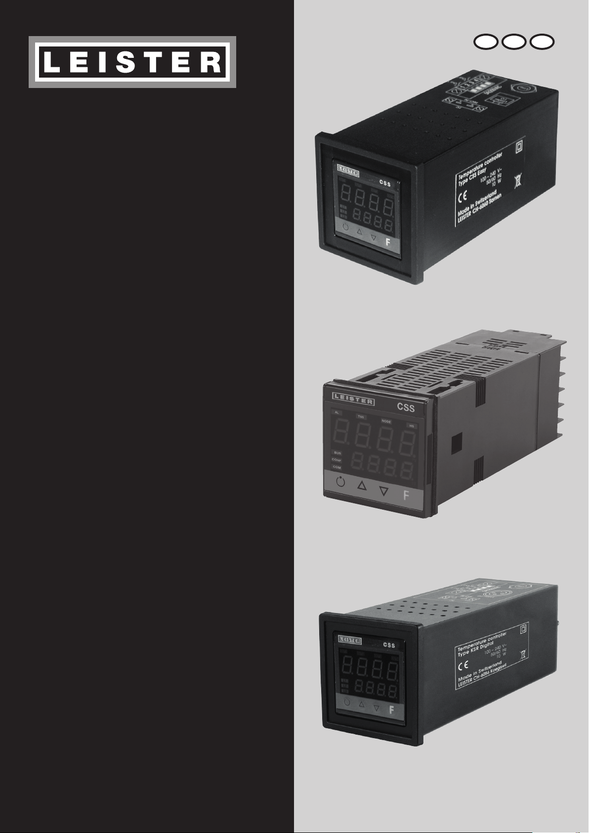
CSS EASY
CSS
®
D GB F
KSR DIGITAL
Leister Technologies AG
Galileo-Strasse 10
CH-6056 Kaegiswil/Switzerland
Tel. +41 41 662 74 74
Fax +41 41 662 74 16
www.leister.com
[email protected]
Page 2

Deutsch Bedienungsanleitung 3
Englisch Operating Instructions 14
Français Instructions d’utilisation 24
2
Page 3
Bedienungsanleitung
(Original-Bedienungsanleitung)
Bedienungsanleitung vor Inbetriebnahme aufmerksam lesen und zur weiteren Verfügung
aufbewahren.
Leister CSS EASY / CSS / KSR DIGITAL
Temperaturregler
Warnung
Lebensgefahr beim Önen des Gerätes, da spannungsführende Komponenten und Anschlüsse
freigelegt werden. Vor dem Öffnen des Gerätes muss dieses allpolig vom Netz getrennt werden.
Vorsicht
D
100
230
Service und Reparatur
Reparaturen sind ausschliesslich von autorisierten Leister-Service-Stellen ausführen zu lassen. Diese gewährleisten innert
24 Stunden einen fachgerechten und zuverlässigen Reparatur-Service mit Original-Ersatzteilen gemäss Schaltplänen und
Ersatzteillisten.
Gewährleistung
Nennspannung, die auf dem Gerät angegeben ist, muss mit der Netzspannung übereinstimmen.
Gerät vor Feuchtigkeit und Nässe schützen.
• Für dieses Gerät gelten die vom direkten Vertriebspartner/Verkäufer gewährten Garantie- oder Gewährleistungsrechte
ab Kaufdatum. Bei einem Garantie- oder Gewährleistungsanspruch (Nachweis durch Rechnung oder Lieferschein) werden
Herstellungs- oder Verarbeitungsfehler vom Vertriebspartner durch Ersatzlieferung oder Reparatur beseitigt. Heizelemente
sind von der Gewährleistung oder Garantie ausgeschlossen.
• Weitere Garantie- oder Gewährleistungsansprüche werden im Rahmen des zwingenden Rechts ausgeschlossen.
• Schäden, die auf natürliche Abnutzung, Überlastung oder unsachgemässe Behandlung zurückzuführen sind, werden von
der Gewährleistung ausgeschlossen.
• Keine Garantie- oder Gewährleistungsansprüche bestehen bei Geräten, die vom Käufer umgebaut oder verändert wurden.
3
Page 4

Einbauerklärung
(Im Sinne der EG-Maschinenrichtlinie 2006/42; Anhang II B)
Leister Technologies AG, Galileo-Strasse 10, CH-6056 Kaegiswil/Schweiz erklärt hiermit, dass die unvoll ständige
Maschine
Bezeichnung: Temperaturregler
Typ: CSS; CSS EASY; KSR DIGITAL
– soweit es vom Lieferumfang her möglich ist – den anwendbaren grundlegenden Anforderungen der EG-Maschinen richtlinie
(2006/42) entspricht.
Die unvollständige Maschine entspricht überdies den Anforderungen der folgenden EG-Richtlinie(n):
EG-Richtlinie(n): 2014/30, 2014/35, 2011/65
Harmonisierte Normen: EN 61326-1:2013, EN 61010-1:2010, EN 50581:2012
Ferner erklären wir, dass für diese unvollständige Maschine die speziellen technischen Unterlagen gemäss Anhang VII
(Teil B) erstellt wurden und verpflichten uns, diese auf begründetes Verlangen den Marktüberwachungsbehörden elektronisch
zu übermitteln.
Name des Dokumentationsbevollmächtigten: Volker Pohl, Manager Product Conformity
Die Inbetriebnahme der unvollständigen Maschine wird so lange untersagt, bis gegebenenfalls festgestellt wurde, dass die
Maschine, in die die unvollständige Maschine eingebaut wurde, den Bestimmungen der EG-Maschinenrichtlinie (2006/42)
entspricht.
Kaegiswil, 17.11.2017
Bruno von Wyl, CTO Christoph Baumgartner, GM
Entsorgung
Elektrogeräte, Zubehör und Verpackungen sollen einer umweltgerechten Wiederverwertung zugeführt werden. Nur für
EU-Länder: Werfen Sie Elektrogeräte nicht in den Hausmüll!
4
Page 5
INSTALLATION
48
70
63
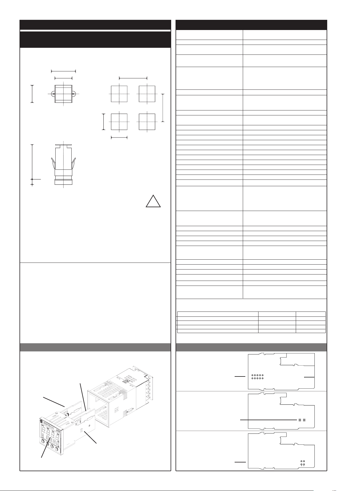
Außen- und Ausschnittmaße; Schalttafeleinbau
48
45
99
10
70
45
!
Für eine einwandfreie
Installation sind
die Hinweise der
Bedienungsanleitung zu
befolgen.
Schalttafeleinbau:
Zur Befestigung des Instruments die beiliegenden Befestigungselemente benutzen. Zur Befestigung
mehrerer Geräte neben- oder untereinander Ausschnittsmaße aus oberer Abbildung entnehmen.
ANWENDUNG: Der Regler ist für Anwendungen im Industriebereich nach EN 61000-6-2 und EN 610006-4 vorgesehen.
WARTUNG: Das Gerät ist wartungsfrei.
Das Gehäuse nicht mit Lösemitteln auf Kohlenwasserstobasis (Trichlorethylen, Benzin usw.) reinigen,
da andernfalls die mechanische Zuverlässigkeit des Geräts beeinträchtigt werden könnte. Zum
Reinigen der Außenflächen aus Kunststo ein sauberes, mit Ethylalkohol oder Wasser angefeuchtetes
Tuch verwenden.
TECHNISCHER KUNDENDIENST: LEISTER bietet mit einer eigenen Kundendienstabteilung technische
Unterstützung an.
TECHNISCHE DATEN
Anzeige
Tasten 4 Tasten (Man/Auto., Auf, Ab, F)
Genauigkeit
Haupteingang
(einstellbarer Digitalfilter)
Typ
Thermoelemente (ITS90)
Kompensationsfehler 0,1° / °C
Typ des RTD. (Skala im angegebenen Bereich einstellbar,
mit und ohne Dezimalpunkt)
Max. Leitungswiderstand für RTD
PTC / NTC 990Ω 25°C / 1KΩ 25°C
Sicherheit
C° / F° Umschaltung über Tastenfeld konfigurierbar
Lineare Skalenbereiche -1999 ... 9999, mit konfigurierbarem Dezimalpunkt
Regelungsfunktionen PID, Optimierungen, EIN/AUS
pb - dt - it 0,0...999,9 % - 0,00...99,99 min - 0,00...99,99 min
Regelungstypen Heizen
Ausgangsfunktionen EIN/AUS, stetig
Begrenzung der max. Leistung Heizen
Zykluszeit 0...200 s
Regelungsausgang Relais, Logik, stetig (0....10V / 4...20mA)
Softstart 0,0...500,0 min
Stellgradbegrenzung bei Fehlfunktion des Fühlers
Standby-Funktion
3 Konfigurierbare Alarme
Alarmsonderfunktionen
Relaiskontakt
Logik-Ausgang für Halbleiterrelais 24V ±10% (10V min zu 20mA)
Sensorspeisung 15/24VDC, max 30mA, kurzschlussfest
Analogausgang 10V/20mA Rlast max 720Ω Auflösung 12 Bit
Spannungsversorgung
(Weitbereichsschaltnetzteil)
Schutzart Bedienfront IP65
Betriebs-/Lagertemperatur 0...50°C / -20...70°C
Relative Luftfeuchtigkeit 20...85% nicht kondensierend
Klimabedingungen sie des Gebrauches für nur internen Gebrauch, Höhe bis bis 2000m
Installation Schalttafeleinbau, von vorn herausnehmbar
Gewicht CSS EASY
CSS
KSR Digital
FUNKTION KABELTYP KABELLÄNGE
Anschlussleitung 1 mm2 1 m
Drähte Relaisausgang 1 mm2 3,5 m
Fühler Eingang Thermoelement 0,8 mm2 kompensiert 5 m
Fühler Eingang Widerstandsthermometer PT100 1 mm2 3 m
(ITS90)
Die EMV-Konformität wurde mit folgenden Verbindungen geprüft:
2 x 4-stellige 7-Segment-LED Anzeige, Ziernfarbe
grün, Ziernhöhe 10 und 7 mm
0,2% vom Skalenendwert ± 1 digit bei
Umgebungstemperatur 25°C
TC, RTD, PTC, NTC
60mV, 1V Ri≥1MΩ; 5V, 10V Ri≥10kΩ; 20mA Ri=50Ω
Abtastrate 120 ms
Typ Thermoelemente: J, K, R, S, T, (IEC 584-1,
CEI EN 60584-1, 60584-2) die kundenspezifische
Linearisierung ist möglich. B, E, N, L GOST, U, G, D, C
seien Sie vorhanden, indem Sie die kundenspezifische
Linearisation verwenden.
DIN 43760 (Pt100), JPT100
20Ω
Kurzschluss- und Fühlerbrucherkennung,
Plausibilitätsalarm, Heizstromalarm
0,0...100,0 %
0,0…100,0 %
Istwertanzeige, Regelung deaktiviert
Bis zu 3 Alarm-Funktionen, die konfiguriert und einem
Ausgang zugeordnet werden können;
Typ: Höchstwert, Mindestwert, symmetrische Werte,
Absolut-/Relativwerte, Plausibilitätsalarm, Heizstromalarm
- Unterdrückung während der Einschaltphase
- Zurücksetzen des Alarmspeichers über Taste oder
Digitaleingang
Schließer 5A, 250V/30Vdc cosϕ=1
100… 240 V AC ±10%
50/60 Hz, max. 8VA
450 g
200 g
450 g
Leiterplatten Aufbau des Instruments
POWER- Karte
OUT4
CPU
Wahl der
TransmitterVersorgungsspannung
OUT4-Karte
15V
10V5V1,23V
24V
S oen:
Strom-Ausgangssignal
S geschlossen
Spannung-Ausgangssignal
S
CPU- Karte
POWER
+VT
DISPLAY
5
Wahl des Signals an
Kontakt 3
PT100
Page 6
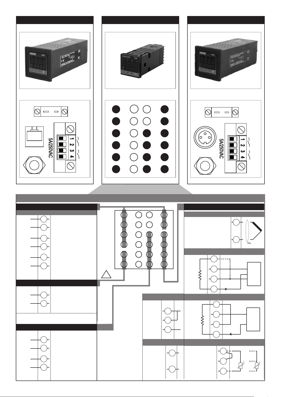
CSS CSS EASY KSR DIGITAL
TC
K
+
NiCr-Ni
Leister
I/O
Line
Alarmausgang 1 + 2 / Logikausgang
Konfigurierbarer Ausgang
-
Out2
+
Out1
Out3
19
- Logik 24V, 10V zu 20mA
20
21
- Relais 5A zu 250Vac/30Vdc
(Alarmausgang 1)
22
6
- Relais 5A zu 250Vac/30Vdc
(Alarmausgang 2)
5
Stromversorgung
PWR
~
~
23
100 ... 240 VAC ± 10%
24
Ausgänge
+
OUTPWR
-
-
Out4
+
9
- Speisespannung 24 VDC für LeisterSYSTEM -Elektronik
10
11
- Ausgangssignal 4 – 20 mA
(0 – 20 mA / 0 – 10 VDC)
12
Out 1
Out 3
19
20
21
22
23
24
18
17
16
15
14
13
7
8
9
10
11
12
Anschlussbelegung CSS
19
20
21
22
23
24
18
17
16
15
14
13
7
8
9
10
11
12
!
• Linearsignal (I)
Eingang
für lineares
Gleichst-
romsignal
20mA,
Ri = 50Ω
• Linearsignal (V)
Eingang für
lineares
Gleichspannungs-
signal
60mV, 1V
Ri > 1MΩ
5V, 10V
Ri > 10KΩ
6
K
+
5
4
3
2
1
Leister I/O
Line
NiCr-Ni
Out 1
Out 3
Eingänge
TC
6
5
4
3
2
1
Verfügbare Thermoelemente
J, K, R, S, T
(B, E, N, L, U, G, D, C kundenspezifische
Linearisation ist vorhanden)
- Polarität beachten
- Für Leitungsverlängerungen eine für das
Thermoelement geeignete Kompensationsleitung
verwenden.
• Lineareingang für 3-Leiter-Transmitter
Ri = 50Ω
• Lineareingang für 2-Leiter-Transmitter
-
4
2
+
1
-
2
+
1
Ri = 50Ω
Drähte mit
angemessenen
Querschnitt verwenden
(min. 1mm2)
PT100, JPT100,
PTC, NTC
• TC
:
Verbindung für 20 mA Eingang herstellen.
4
VT
+ 24V o 15V
3
-
2
+
1
4
+ 24V o 15V
VT
3
-
2
4...20mA
+
1
• Pt100 / PTC / NTC
3
2
1
PTC / NTC / Pt100
2
1
2 leiter
+
S
+
-
T
-
+
-
T
Pt100 3 leiter
6
Page 7
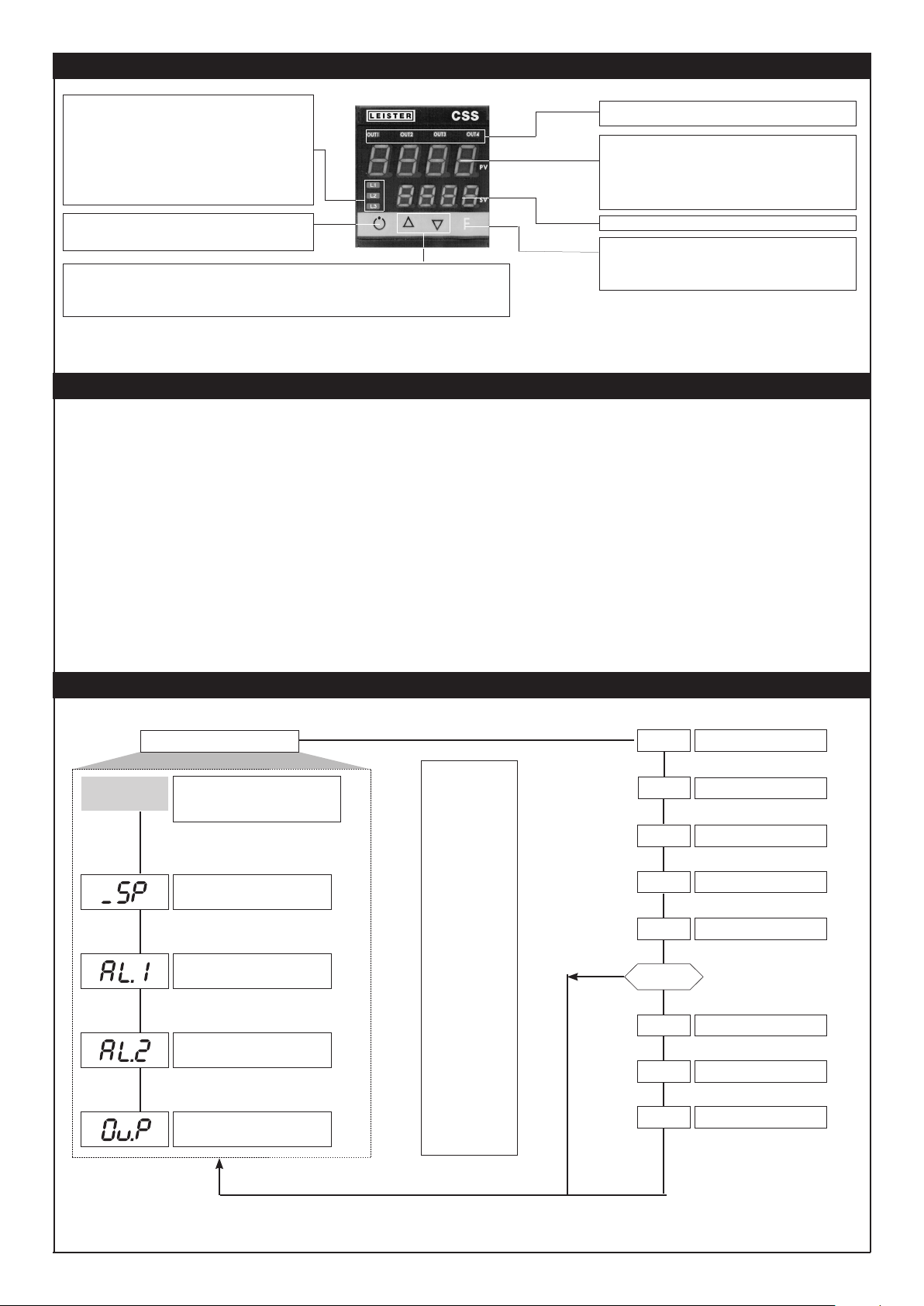
BEDIEN- UND ANZEIGEELEMENTE
Sie signalisieren die Betriebsart des Instruments:
L1 MAN/AUTO = AUS (automatische Regelung)
EIN (manuelle Steuerung)
L2 SETPONT1/2 = AUS (IN1= AUS - interner Sollwert 1)
EIN (IN1= EIN - interner Sollwert 2)
L3 SELFTUNING = EIN (Self aktiviert)
AUS (Self deaktiviert)
Wahl der automatische Regelung / manuellen Steuerung:
Nur aktiv, wenn die PV-Anzeige den Istwert anzeigt
Mit diesen Tasten werden numerische Parameter verändert •• Die Geschwindigkeit der Veränderung ist proportional zur Dauer der
Betätigung der Taste •• Der Vorgang ist nicht zyklisch, d.h. nach Erreichen des Min.- bzw. Max. Wertes eines Parameters ändert sich
dieser nicht mehr, auch wenn weiterhin die Taste gedrückt wird.
Funktionsanzeige
Taste „Auto/Man“
Tasten „Auf“ und „Ab“
Für den Zugri auf die verschiedenen Konfigura-tionsparameter •• Zum Bestätigen
der eingegebenen Parameter und Weitersprung zum nächsten Parameter. Bei
gleichzeitiger Betätigung der Taste Auto/Man zum Zurückspringen zum vorherigen
Parameter.
Zustandsanzeige der Ausgänge
OUT 1 (AL 1); OUT 2 (Main); OUT 3 (AL 2); OUT 4
PV-Anzeige: Istwert
Fehleranzeige: LO, HI, Sbr, Err
LO = der Istwert unterschreitet die Skalengrenze (LO_S)
HI = der Istwert überschreitet die Skalengrenze (HI_S)
Err = dritter Leiter bei PT100/PTC unterbrochen
Sbr = Sensorbruch
SV-Anzeige: Sollwert
Funktionstaste F
SOFTWARE EINSTELLUNG
Die Temperaturregler werden von Leister Technologies AG mit vorprogrammierter Grundeinstellung
ausgeliefert. Diese Einstellungen können nach Bedarf vom Nutzer verstellt werden (Temperatureingang,
Regelverhalten etc.).
Die Werte der Grundeinstellung sind jeweils unter dem dazugehörigen Menü-Punkt vermerkt und gelten für
alle CSS- EASY und CSS.
KSR-DIGITAL haben typenspezifische Einstellungen, welche bei Leister Technologies AG angefragt werden
können.
PROGRAMMIERUNG und KONFIGURATION
Informationsdisplay
Kundenspezifisches Menü
Eingangskonfiguration
Ausgangskonfiguration
Passwort
Zugriscode
Hardware-Konfiguration
Kundenspezifische Kalibration
P.V. / S.V.
Default: 650
Default: 650
ANZEIGEEBENE 1
Istwert (PV-Anzeige)
Sollwert (SV-Anzeige) oder Stellgröße bei
Handbetrieb des Reglers
Sollwert
Alarmwert 1
Alarmwert 2
Stellgrad (in %)
F-Taste tippen um
einzelne Parameter eines
Menüs zu erreichen.
F-Taste gedrückt halten
um Menü zu verlassen.
F-Taste lösen um das
gewünschte Menü zu
aktivieren.
Auto/Man und F-Taste
tippen um sich rückwärts
im Menü zu bewegen.
F-Taste und Auto/Man
Taste für ca. 2s. gedrückt
halten, um in die PV/
SV-Anzeige zu gelangen.
Durch Drücken der
Tasten Auto/Man + F in
einem beliebigen Menü
kann man direkt zum
vorherigen Parameter
springen.
NEIN
INF
CFG
InP
Out
PAS
PAS = 99
Pro
Hrd
U.CA
Hinweis: Die für eine spezifische Konfiguration nicht benötigten Parameter, werden in den Menüs ausgeblendet.
7
Page 8
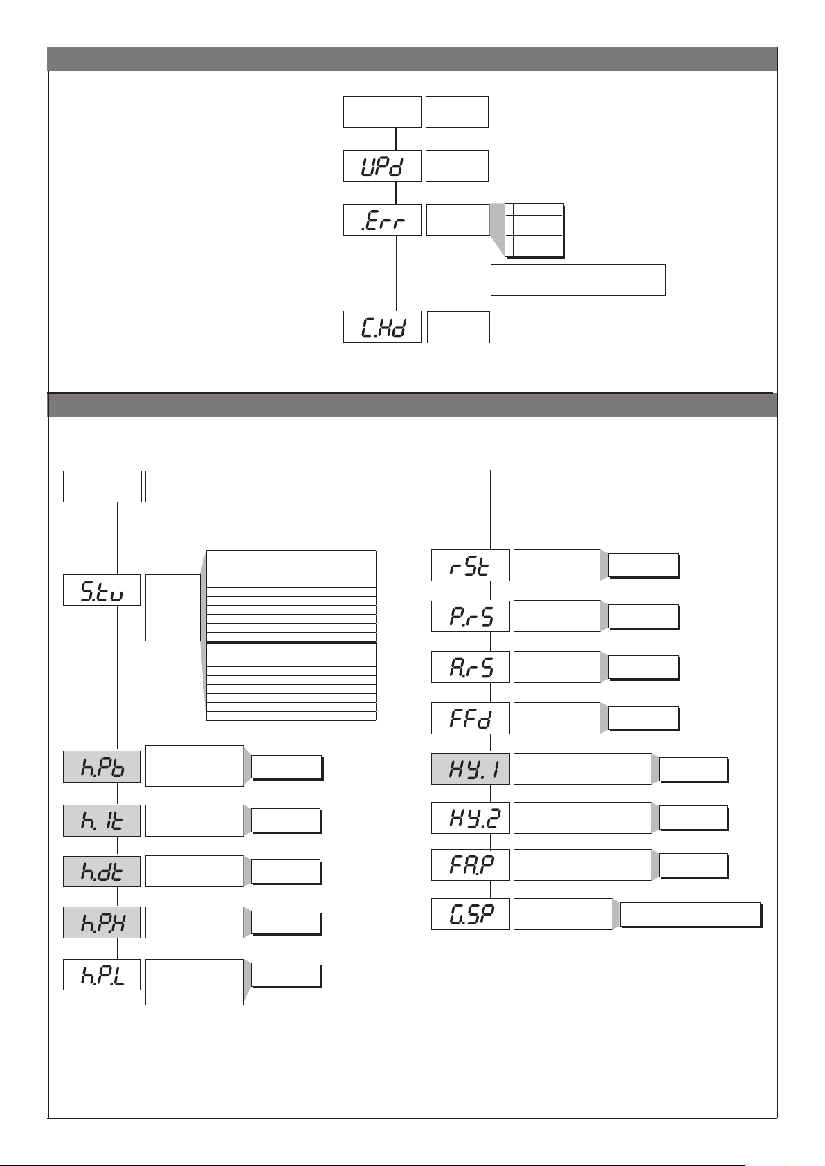
Informationsmenü
CFG
Regelparameter
Default: 3.10
Default: 4
Default: 213
INF
CFG Menü
Informations-
menü
Software-Version
Fehleranzeige
Konfiguration hrd
0 No Error
1 Lo
2 Hi
3 ERR
4 SBR
+8 Fehler Erkennung Karte OUT2
+16 Fehler Erkennung Karte OUT3
Default: 0
Default: 30
Default: 0.2
Default: 0.01
Default: 100
Default: 0
S.tun
Aktivierung
Selbstoptimie-
rung,
Autooptimie-
rung,
Softstart
Proportionalbereich
Heizen oder Hysteresis in
vorgeschriebenem AN/AUS
Obere Stellgradbegrenzung
Untere Stellgradbegrenzung
(nicht verfügbar für doppelte
Wirkungsweise Heizen/Kühlen)
0 NEIN NEIN NEIN
1 YA NEIN NEIN
2 NEIN YES NEIN
3 YES YES NEIN
4 NEIN NEIN YA
5 YA NEIN YA
6 - - 7 - - -
S.tun
8 WAIT NEIN NEIN
9 GO NEIN NEIN
10 WAIT YA NEIN
11 GO YA NEIN
12 WAIT NEIN YA
13 GO NEIN YA
Integralzeit
für Heizen
Dierentialzeit
für Heizen
für Heizen
für Heizen
Continuous
autotuning
Autotuning
one shot
0 ... 999.9% v.Ew.
0.00 ... 99.99 min
0.00 ... 99.99 min
Selftuning Softstart
Selftuning Softstart
0.0 ... 100.0%
0.0 ... 100.0%
Default: 0
Default: 0
Default: 0
Default: 0
Default: -1
Default: -1
Default: 0
Default: 0
Manuelles Zurücksetzen
Proportionalbandver-
schiebung
Antireset
Vorausregelung
Hysterese für Alarm 1
Hysterese für Alarm 2
Stellgradbegrenzung bei Fühlerdefekt
Sollwertgradient
(siehe Anwendungshinweise)
Skaleneinheiten
-100.0 ... 100.0%
Skaleneinheiten
-100.0 ... 100.0%
-999 ... 999
0 ... 9999
± 999
Skaleneinheiten
± 999
Skaleneinheiten
-100.0 ... 100.0%
ON / OFF
0,0...999,9 Skaleneinheiten/min.
(Skaleneinheiten / s siehe SP.ty)
8
Page 9
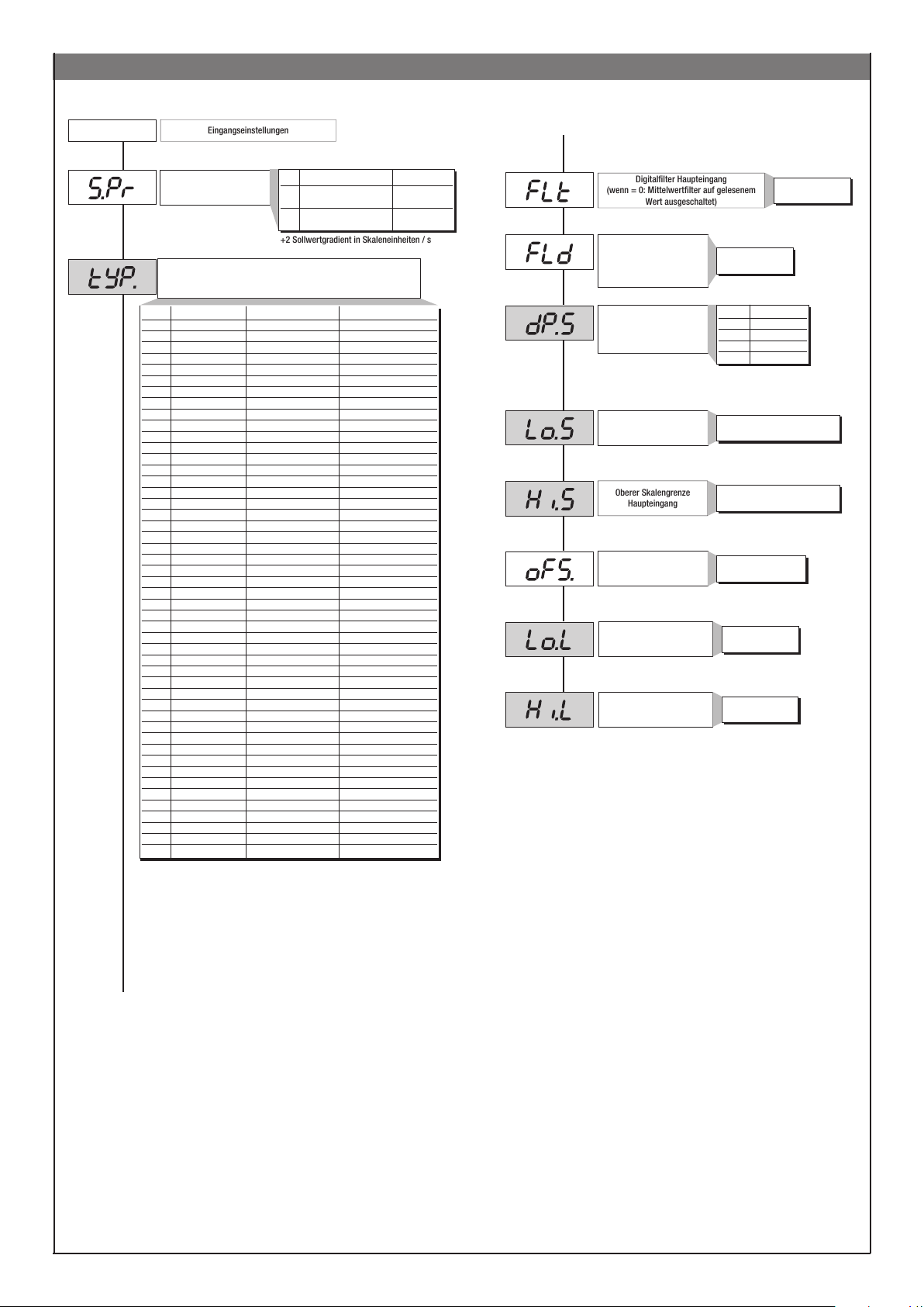
InP
Eingangseinstellungen
+2 Sollwertgradient in Skaleneinheiten / s
Digitalfilter Haupteingang
(wenn = 0: Mittelwertfilter auf gelesenem
Wert ausgeschaltet)
Oberer Skalengrenze
Haupteingang
InP Menü
Default: 0
Default: 2
Def. externer Sollwert
Fühlertyp, Signal, Aktivierung der Kundenspezifischen Linearisierung
Type Fühlertyp Ohne Dezimalpunkt Mit Dezimalpunkt
Sensore: TC
0 TC J °C 0/1000 0.0/999.9
1 TC J °F 32/1832 32.0/999.9
2 TC K °C 0/1300 0.0/999.9
3 TC K °F 32/2372 32.0/999.9
4 TC R °C 0/1750 0.0/999.9
5 TC R °F 32/3182 32.0/999.9
6 TC S °C 0/1750 0.0/999.9
7 TC S ° F 32/3182 32.0/999.9
8 TC T °C -200/400 -199.9/400.0
9 TC T °F -328/752 -199.9/752.0
28 TC CUSTOM CUSTOM
29 TC CUSTOM CUSTOM
30 PT100 °C -200/850 -199.9/850.0
31 PT100 °F -328/156 2 -199.9/999.9
32 JPT100 °C -200/600 -199.9/600.0
33 JPT100 °F -328/1112 -199.9/999.9
34 PTC °C -55/120 -55.0/120.0
35 PTC °F -67/248 -67.0/248.0
36 NTC °C -10/70 -10.0/70.0
37 NTC °F 14/158 14.0/158.0
38 0...60 mV -1999/9999 -199.9/999.9
39 0...60 mV
40 12...60 mV -1999/9999 -199.9/999.9
41 12...60 mV
42 0...20 mA -1999/9999 -199.9/999.9
43 0...20 mA
44 4...20 mA -1999/9999 -199.9/999.9
45 4...20 mA
46 0...10 V -1999/9999 -199.9/999.9
47 0...10 V
48 2...10 V -1999/9999 -199.9/999.9
49 2...10 V
50 0...5 V -1999/9999 -199.9/999.9
51 0...5 V
52 1...5 V -1999/9999 -199.9/999.9
53 1...5 V
54 0...1 V -1999/9999 -199.9/999.9
55 0...1 V
56 200mv..1V -1999/9999 -199.9/999.9
57 200mv..1V
58 Cust10 V-20mA -1999/9999 -199.9/999.9
59 Cust10 V-20mA
60 Cust 60mV -1999/9999 -199.9/999.9
61 Cust 60mV
62 PT100-JPT CUSTOM CUSTOM
63 PTC CUSTOM CUSTOM
64 NTC CUSTOM CUSTOM
und Skala des Haupteingangssignals
Val. Typ externer Sollwert Absolut/Relativ
0 Digital Absolut
(über serielle Schnittstelle)
1 Digital relativ zum
(über serielle Schnittstelle) internen Sollwert
kundenspez. Linearisierung kundenspez. Linearisierung
kundenspez. Linearisierung kundenspez. Linearisierung
kundenspez. Linearisierung kundenspez. Linearisierung
kundenspez. Linearisierung kundenspez. Linearisierung
kundenspez. Linearisierung kundenspez. Linearisierung
kundenspez. Linearisierung kundenspez. Linearisierung
kundenspez. Linearisierung kundenspez. Linearisierung
kundenspez. Linearisierung kundenspez. Linearisierung
kundenspez. Linearisierung kundenspez. Linearisierung
kundenspez. Linearisierung kundenspez. Linearisierung
kundenspez. Linearisierung kundenspez. Linearisierung
kundenspez. Linearisierung kundenspez. Linearisierung
Default: 0.1
Default: 0.5
Default: 0
Default: 0
Default: 1300
Default: 0
Default: 0
Default: 650
Digitalfilter auf Anzeige des
Eingangs
Dezimalpunkt für
Haupteingangsskala
Untere Skalengrenze
Haupteingang
Korrekturoset Haupteingang
Unterer Grenzwert für die
Einstellung des Sollwerts und
der absoluten Alarme
Oberer Grenzwert für die
Einstellung des Sollwerts und
der absoluten Alarme
0.0 ... 20.0 s
0 ... 9.9
Skaleneinheiten
dP_S Format
0 xxxx
1 xxx.x
2 xx.xx (*)
3 x.xxx (*)
(*) Bei den Skalen für TC,
Widerstandsthermometer, PTC und
RTC nicht verfügbar.
Min. ... Max. der Skala des in tyP
gewählten Eingangs
Min. ... Max. der Skala des in tyP
gewählten Eingangs
-999 ... 999
Skaleneinheiten
Lo.S ... Hi.S
Lo.S ... Hi.S
Zur kundenspezifischen Linearisierung:
- Die LO - Signalisierung geschieht mit Variablen, deren Werte unterhalb von Lo.S oder
des minimalen Kalibrationswerts liegen
- Die HI - Signalisierung geschieht mit Variablen, deren Werte oberhalb von Lo.S oder des
maximalen Kalibrationswerts liegen
9
Page 10
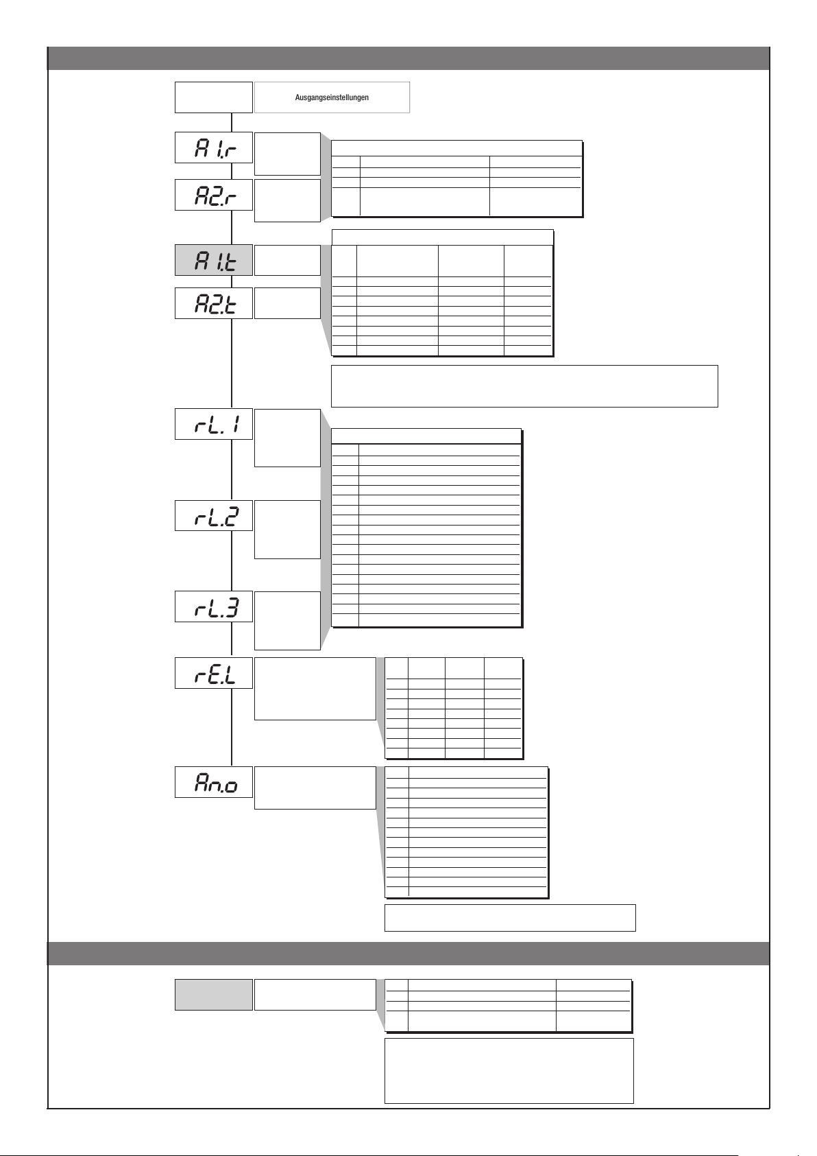
Out
Ausgangseinstellungen
Out Menü
Default: 0
Default: 0
Default: 0
Default: 0
Default: 2
Default: 5
Default: 3
Default: 0
Default: 5
Wahl der
Bezugsgrö-ßen
Alarm 1
Wahl der
Bezugsgrö-ßen
Alarm 2
Typ Alarm 1
Typ Alarm 2
Out1
Vereinbarung der
Ausgangsfunktion
Out2
Vereinbarung der
Ausgangsfunktion
Out3
Vereinbarung der
Ausgangsfunktion
Ausgangsverhalten im falle von
Fühlerbruch Fühlerschluss oder
Fühlerverpolung. Funktion lediglich
für Alarme. Err, Sbr
Funktionsvereinbarung für den
AL.x.r Zu vergleichende Größe Bezugsschwellwert
0 PV (Istwert) AL
1 SSP (aktiver Sollwert) AL (nur absolut)
2 PV (Istwert) AL (nur relativ und
bezogen auf SP1
mit Multiset-Funktion)]
AL.x.t Direkt (Überschreitung) Absolut oder Normal oder
Invers (Unterschreitung) Relativ zum Symmetrisch
aktiven Sollwert (Fenster)
0 direkt absolut normal
1 invers absolut normal
2 direkt relativ normal
3 invers relativ normal
4 direkt absolut
5 invers absolut
6 direkt relativ
7 invers relativ
+8 zur Deaktivierung während der Einschaltphase.
+16 zum Aktivieren des Alarmspeichers
+ 32 Hys wird Verzögerung bei Alarmauslösung (0...999 s) (ausgenommen absoluter symmetrischer Alarm)
+ 64 Hys wird Verzögerung bei Alarmauslösung (0...999 min.) (ausgenommen absoluter symmetrischer Alarm)
Val Funktion
0 Heizen (Regelungsausgang Heizen)
1 Kühlen (Regelungsausgang Kühlen)
2 AL1 - Alarm 1
3 AL2 - Alarm 2
4 AL3 - Alarm 3
5 AL.HB - Alarm HB
6 LBA - Alarm LBA
7 IN - Zustand logischer Eingang
8 Wiederholung Taste but (wenn but = 8)
9 AL1 oder AL2
10 AL1 oder AL2 oder AL3
11 AL1 und AL2
12 AL1 und AL2 und AL3
13 AL1 oder ALHB
14 AL1 oder AL2 oder ALHB
15 AL1 und ALHB
16 AL1 und AL2 und ALHB
+ 32 für invertierten Ausgang, ausgenommen Kodes 0…1 mit stetigem Ausgang
Out W
Analogausgang
AL.1.r, AL.2.r
AL.1.t, AL.2.t
symmetrisch
symmetrisch
symmetrisch
symmetrisch
rL.o.1, rL.o.2, rL.o.3, rL.o.4
_rEL. Alarm Alarm Alarm
1 2 3
0 OFF OFF OFF
1 ON OFF OFF
2 OFF ON OFF
3 ON ON OFF
4 OFF OFF ON
5 ON OFF ON
6 OFF ON ON
7 ON ON ON
Val Bezugsgröße
0 PV - Istwert
1 SSP - aktiver Sollwert
2 SP - interner Sollwert
3 4 Sollwertabweichung (SSP-PV)
5 Heizen
6 Kühlen
7 AL1 (Schwellwert)
8 AL2 (Schwellwert)
9 AL3 (Schwellwert)
10 11
Über serieller Schnittstelle erfasster Wert (*)
16 für Kode 0, wenn Eingang im Fehlerzustand Err - Sbr nimmt
der Ausgang den niedrigsten Einstellwert an.
Pro
Zugangssperre
(PAS 99)
Prot Menü (PAS)
Prot Anzeige Änderung
0 SP, In2, alarme, OuP, INF SP, alarme
1 SP, In2, alarme, OuP, INF SP
2 SP, In2, OuP, INF
+4 zum Sperren von InP, Out
+8 zum Sperren von CFG, Ser
+16 zum Sperren der Software Geräteabschaltung
+32 zum Sperren der Speicherung der manuellen Stellgradvorgabe
+64 zum Sperren der Änderung der manuellen Stellgradvorgabe
+128 Freigabe der erweiterten Konfiguration
10
Page 11
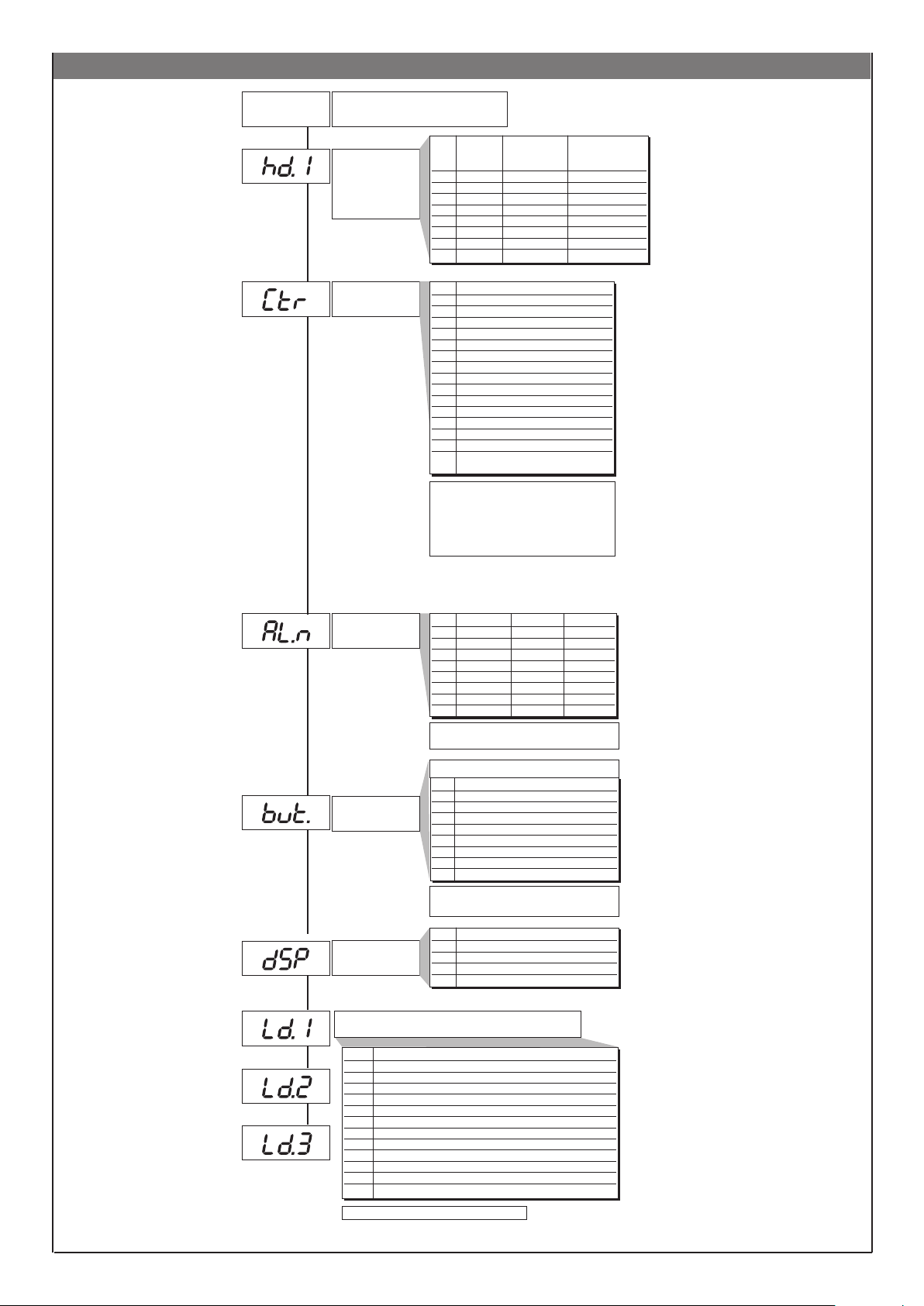
Hrd Menü
Default: 0
Default: 70
Hrd
Hardware-Konfiguration
Freigabe Multiset
Steuerung der
Geräte über serielle
Schnittstelle
Regelungstyp
Val Multiset Status LED Gerätesteuerung
(2 SP) invertiert über serielle
Schnittstelle
0
1 x
2 x
3 x x
4 x
5 x x
6 x x
7 x x x
Val Regelungstyp
0 P heizen
1 P kühlen
2 P heizen / kühlen
3 PI heizen
4 PI kühlen
5 PI heizen / kühlen
6 PID heizen
7 PID kühlen
8 PID heizen / kühlen
9 ON-OFF heizen
10 ON-OFF kühlen
11 ON-OFF heizen / kühlen
12 PID heizen + ON-OFF kühlen
13 ON-OFF heizen + PID kühlen
14
PID heizen + kühlen mit Relativver-
stärkung (siehe Parameter C.MEd)
Wahl der Dierenzierzeit:
+0 Abtastung 1 s
+16 Abtastung 4 s
+32 Abtastung 8 s
+64 Abtastung 240 ms
Default: 3
Default: 1
Default: 0
Wahl der Anzahl der
freigegebenen Alarme
Funktion der MAN /
AUTO Taste
Definition der
Anzeigefunktion SV
Anmerkung: Bei der EIN-AUS-Regelung ist der
LbA-Alarm nicht aktiviert.
AL.nr Alarm 1 Alarm 2 Alarm 3
0 gesperrt gesperrt gesperrt
1 freigegeben gesperrt gesperrt
2 gesperrt freigegeben gesperrt
3 freigegeben freigegeben gesperrt
4 gesperrt gesperrt freigegeben
5 freigegeben gesperrt freigegeben
6 gesperrt freigegeben freigegeben
7 freigegeben freigegeben freigegeben
+8 zum Freigeben von Alarm HB.
+16 zum Freigeben von Alarm LBA.
b u t t
0 Keine Funktion (Taste gesperrt)
1 MAN/AUTO Umschaltung
2 LOC / REM Auswahl
3 HOLD
4 Alarmspeicher zurücksetzen
5 Wahl SP1 / SP2
6 Start / Stop Selbstoptimierung
7 Start / Stop Autooptimierung
8 Set / Reset Ausgänge 1 ... 4
+ 16 deaktiviert die Funktion „back menu“ (Tasten
Auto/Man + F) im Konfigurationsmenü
diSP Funktion der unteren Anzeige (SV)
0 SSP - aktiver Sollwert
1 InP.2 - Hilfseingang
2 Stellgrad
3 Regelabweichung (SSP - PV)
Funktion der LED´s
Default: 1
Default: 10
Default: 20
Val. Funktion
0 keine Funktion
1 MAN/AUTO Umschaltung
2 LOC / REM
3 HOLD
4 Selbstoptimierung aktiviert
5 Autooptimierung aktiviert
6 Digitaleingang IN1 aktiv
7 Datenaustausch über serielle Schnittstelle in Betrieb
8 Anstehender Fehlerzustand
9 Softstart in Betrieb
10 Anzeige SP1...SP2
11 Sollwertgradient in Ausführung
+ 16 LED blinkt, wenn aktiv
11
Page 12
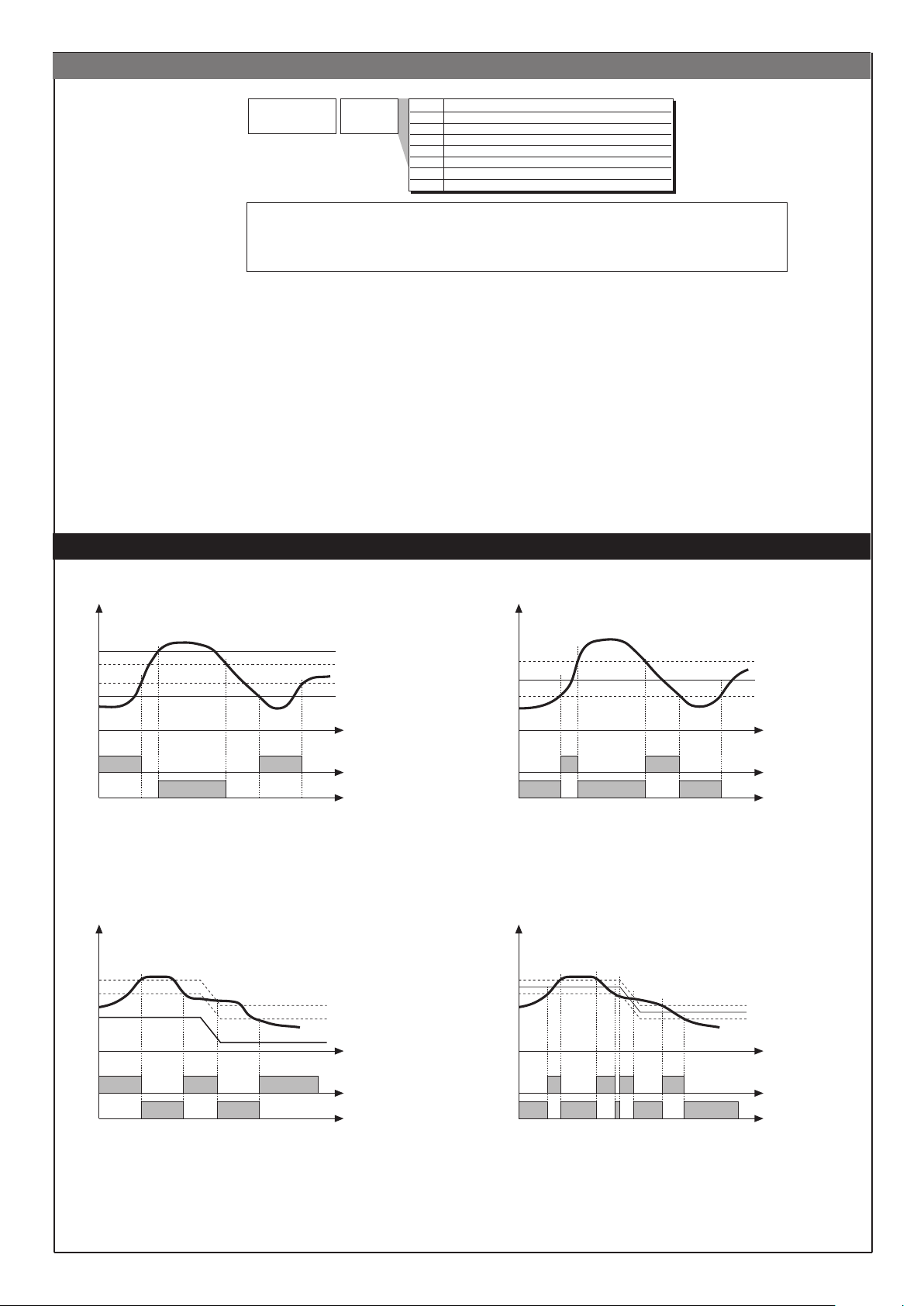
U.CAL Menü
Val Funktion
1 Analoger Ausgang (1)
2 Eingang 1 – kundenspezifisch 10V / 20mA
3 Haupteingang - Fühler kundenspezifisch 60 mV
4 Fühler kundenspezifisch RTD
5 Kundenspezifische PT100 / J PT100
6 Fühler kundenspezifisch NTC
7 Haupteingang 2 - Fühler kundenspezifisch TA (2)
Default: 0
U.CA
Kalibration
durch
Benutzer
(1) Der Analogausgang mit 20mA ist mit einer Genauigkeit besser als 0,2% v. Ew. kalibriert.
Bei Umwandlung in Ausgang 10V Kalibration durchführen.
(2) Die Genauigkeit ohne Kalibration ist besser als 1% v. Ew.; die Kalibration nur durchführen,
wenn eine höhere Genauigkeit erforderlich ist.
ALARME
Absolutalarm Symmetrischer Absolutalarm
AL2
AL1
alarm 1
alarm 2
Für AL1 = inverser absoluter Alarm (Unterschreitung) mit positiver Hysterese Hyst 1, AL1
t = 1
(*) = Aus, wenn während der Einschaltphase aktiviert.
Für AL2 = direkter absoluter Alarm (Überschreitung) mit negativer Hysterese Hyst 2, AL2
t = 0
SP+AL1
(*)
Relativalarm Symmetrischer Relativalarm
SP
AL2 + Hyst2
AL1 + Hyst1
Zeit
Hyst1
AL1 + [ Hyst1 * ]
AL1
AL1 - [ Hyst1 * ]
Zeit
invers
direkt
Für AL1 = absoluter inverser symmetrischer Alarm mit Hysterese Hyst 1, AL1 t = 5
Für AL1 = absoluter direkter symmetrischer Alarm mit Hysterese Hyst 1, AL1 t = 4
* Minimum Hysterese = 2 Skaleneinheiten
SP+AL1
SP
SP-AL1
Zeit
invers
direkt
Für AL1 = relativer inverser Alarm mit negativer Hysterese Hyst 1, AL1 t = 3
Für AL1 = relativer direkter Alarm mit negativer Hysterese Hyst 1, AL1 t = 2
Zeit
invers
direkt
Für AL1 = relativer inverser symmetrischer Alarm mit Hysterese Hyst 1, AL1 t = 7
Für AL1 = relativer direkter symmetrischer Alarm mit Hysterese Hyst 1, AL1 t = 6
12
Page 13
HINWEISE ZU DEN REGELUNGSPARAMETERN
Proportionale Regelung:
ist die Bezeichnung für den Wert, dessen Einfluss auf den Ausgang proportional zum Unterschied zwischen Soll- und Istwert ist.
Integrale Regelung:
ist die Bezeichnung für den Wert, dessen Einfluss auf den Ausgang proportional zum Integral der Sollwertdierenz über die Zeit ist.
Vorhalteregelung:
ist die Bezeichnung für den Wert, dessen Einfluss auf den Ausgang proportional zur Änderungsgeschwindigkeit des Istwertes ist.
Einfluss der Proportionalen, Vorhalte- und Integralen Regelung auf die Regelung
* Eine Vergrößerung des Proportionalbandes verringert die Schwingungen, vergrößert aber den durch den I- und den D- Anteil zu korrigierende Regelabweichung.
* Eine Verkleinerung des Proportionalbandes verringert die Regelabweichung, verursacht aber Oszillieren, d.h. Schwankungen der geregelten Variablen (wenn der
Wert des Proportionalbandes zu klein ist, tendiert das System zur Instabilität).
* Eine verstärke Integralregelung, die einer Verkürzung der Nachstellzeit entspricht, trägt dazu bei, die Regelabweichung zu beseitigen, wenn das System sich
stabilisiert hat.
* Eine Erhöhung der Vorhaltezeit verringert die Regelabweichung und die Oszillationsneigung, jedoch nur bis zu einem kritischen Wert, bei dessen Überschreitung
die Regelabweichung anwächst und längeres Oszillieren auftritt.
Wenn der Wert der Nachstellzeit zu groß ist (schwaches Integralverhalten), kann sich eine ständige Regelabweichung bilden.
Wenn das der Fall ist, sollte das Proportionalband verkleinert und die Vorhalte- und Nachstellzeit zur Erzielung eines besseren Ergebnissen vergrößert werden.
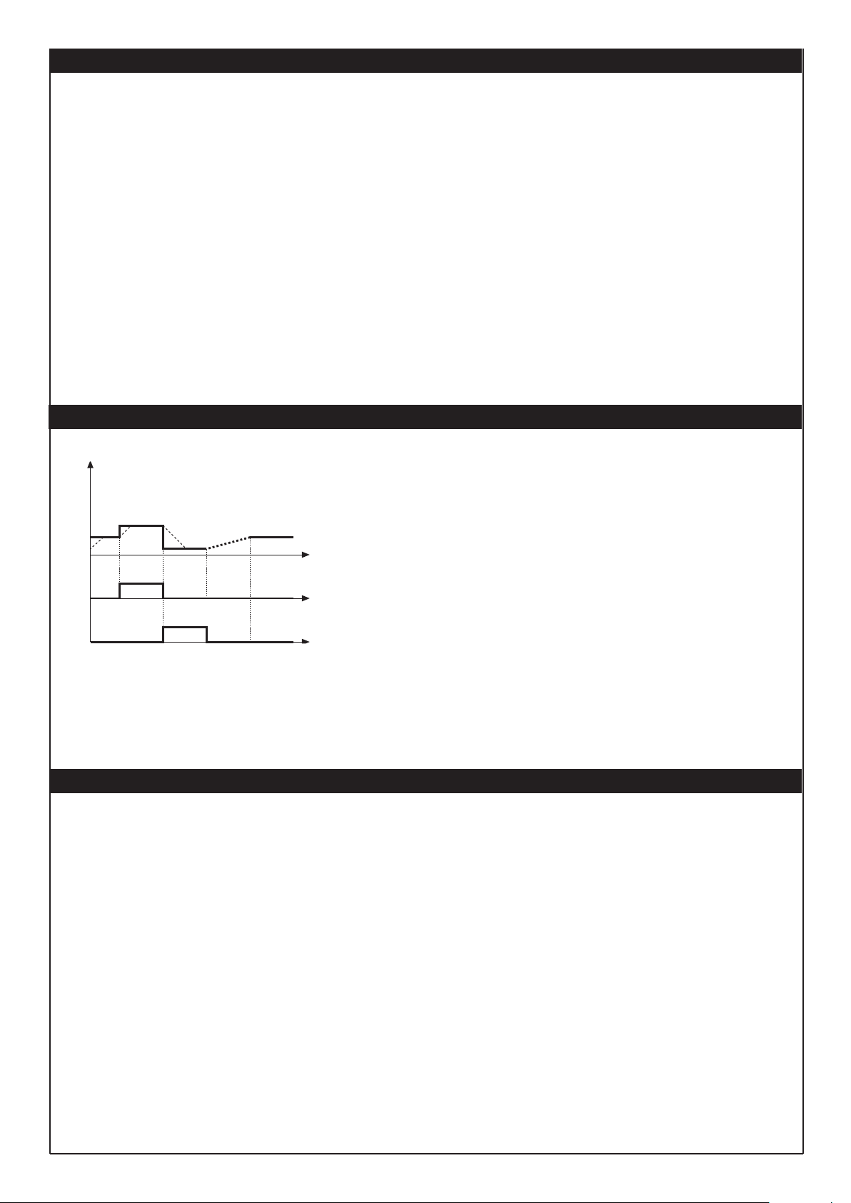
FUNKTION MULTISET, SOLLWERTGRADIENT
Die Multiset-Funktion wird bei hd.1 aktiviert.
Die Funktion Gradient ist immer aktiviert.
Die Wahl zwischen Sollwert 1 und Sollwert 2 kann mit dem Tastenfeld auf der Bedienfront
oder über den digitalen Eingang erfolgen.
Die Wahl zwischen Sollwert 1 und 2 kann mit LED signalisiert werden.
SOLLWERTGRADIENT: Wird ein Sollwertgradient π 0 eingegeben, wird beim Einschalten
oder beim Übergang von Automatik auf Handbetrieb zunächst der Sollwert gleich dem
Istwert gesetzt; anschließend wird der interne oder gewählte Sollwert in Abhängigkeit vom
t
eingegebenen Sollwertgradienten angefahren.
Bei jeder Sollwertänderung erfolgt die Anpassung mit einem Sollwertgradienten.
Der Sollwertgradient ist beim Einschalten gesperrt, wenn die Selbstoptimierung aktiviert
t
ist.
Wird ein Sollwertgradient π 0 eingegeben, dann hat er auch für die nur im zugehörigen
t
SP-Menü einstellbaren Änderungen des internen Sollwerts Wirkung.
Der Regelsollwert wird mit der durch den Gradienten festgelegten Geschwindigkeit
angefahren.
LOC/REM
SP
IN1
SP1
SP2
SPrem
ON
ON
(*) wenn der Sollwertgradient
eingegeben wurde
SP1
(*)
GERÄTE AKTIVIERUNG DEAKTIVIERUNG MITTELS SOFTWARE
Ausschalten: Durch gleichzeitige Betätigung der „F“ und „Ab“ Taste, Betätigungsdauer länger als 5 Sekunden, kann das Instrument deaktiviert werden. Das Gerät
versetzt sich selbst in den Zustand AUS, wobei die Netzversorgung aufrechterhalten wird. Während dieses Phase wird die untere Anzeige (SV) deaktiviert. Alle
Ausgänge (Alarmausgänge sowie Regelausgänge)
nehmen den Zustand AUS an (Logikausgänge auf 0 oder Relais abgefallen). Alle Gerätefunktionen bis auf die Istwerterfassung und Darstellung sowie der
Einschaltfunktion sind deaktiviert.
Einschalten: Durch Betätigung der „F“ Taste, Betätigungsdauer länger als 5 Sekunden. Das Gerät wechselt vom Zustand AUS in den Zustand EIN. Wenn während der
Ausschaltphase die Stromversorgung unterbrochen wird, kehrt er bei
Wiedereinschalten der Regler in den Zustand „AUS“ zurück. Bei der Standardauslieferung ist die EIN / AUS Funktion freigegeben. Sie kann deaktiviert werden,
indem der Parameter Pro wie folgt eingestellt wird: Pro = Prot + 16.
Diese Funktion kann einem Digitaleingang zugeordnet werden.
13
Page 14
Operating Instructions
Please read operating instructions carefully before use and keep for further reference.
Leister CSS EASY / CSS / KSR DIGITAL
Temperature controller
Warning
Danger! When opening up the tool, live components and connections are exposed. The mains plug must be
removed from the main socket before opening up the tool. Caution separate source voltage.
Caution
GB
100
230
Service and Repair
Repairs should only be carried out by authorised Leister Service Centres. They guarantee
within 24 hours using original spare parts in accordance
Warranty
For this tool, we generally provide a warranty of one (1) year from the date of purchase (verified by invoice or delivery document).
Damage that has occurred will be corrected by replacement or repair..
Additional claims shall be excluded, subject to statutory regulations.
Damage caused by normal wear, overloading or improper handling is excluded from the guarantee.
Guarantee claims will be rejected for tools that have been altered or changed by the purchaser.
Declaration of incorporation
(As defined by the EC Machinery Directive 2006/42; Annex II B)
Leister Technologies AG, Galileo-Strasse 10, CH-6056 Kaegiswil/Switzerland hereby declares that the incomplete machine
Designation: Temperature controller
Type: CSS; CSS EASY; KSR DIGITAL
– insofar as is possible from the scope of supply – corresponds to the applicable fundamental requirements of the EC Machinery Directive
(2006/42).
The incomplete machine furthermore corresponds to the requirements of the following EC directive(s):
EC directive(s): 2014/30, 2014/35, 2011/65
Harmonised standards: EN 61326-1:2013, EN 61010-1:2010, EN 50581:2012
We furthermore declare that the special technical documents pursuant to Annex VII (Part B) have been compiled for this
incomplete machine and that we are committed to communicate these electronically to the market surveillance authorities upon
justified request.
Name of the documentation ocer: Volker Pohl, Manager Product Conformity
The commissioning of the incomplete machine is prohibited until it may be determined that the machine in which the incomplete
machine has been installed corresponds to the provisions of the EC Machinery Directive (2006/42).
Kaegiswil, 17.11.2017
The voltage rating stated on the tool must correspond to the mains voltage.
Protect tool from damp and wet.
a correct and reliable repair service
with the circuit diagrams and spare parts lists.
Bruno von Wyl, CTO Christoph Baumgartner, GM
Disposal
Electrical equipment, accessories and packaging should be recycled in an environmentally friendly way. For EU countries
only: Do not dispose of electrical equipment with household refuse!
14 14
Page 15
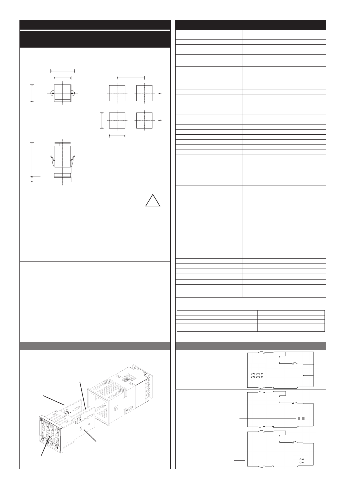
INSTALLATION
Dimensions and cut-out; panel mounting
63
48
45
45
99
10
TECHNICAL SPECIFICATIONS
Display
Keys 4 mechanical keys (Man/Aut, INC, DEC, F)
Accuracy
Main input
(settable digital filter)
70
Type TC Thermocouples
(ITS90)
Cold junction error 0,1° / °C
RTD type (scale configurable within indicated range,
with or without decimal point)
70
Max line resistance for RTD
PTC / NTC 990Ω 25°C / 1KΩ 25°C
Safety
°C / °F selection configurabile da tastieraconfigurable from faceplate
Linear scale ranges -1999 to 9999 with configurable decimal point position
Controls PID, Self-tuning, on-o
pb - dt - it 0,0...999,9 % - 0,00...99,99 min - 0,00...99,99 min
Action Heat
Control outputs on / o, continuous
Maximum power limit heat 0,0...100,0 %
Cycle time 0...200 sec
Main output type relay, logic, continuous (0....10V / 4...20mA)
Softstart 0,0...500,0 min
Fault power setting
Standby-funktion
3 Configurable alarms
(ITS90)
!
2 x 4 digits, 7-segment-LED display, green,
height 10 and 7mm
0.2% full scale ± 1 digit at
25°C room temperature
TC, RTD, PTC, NTC
60mV,1V Ri≥1M
Sampling time 120 msec.
Type TC Thermocouples : J,K,R,S,T (IEC 584-1, CEI EN
60584-1, 60584-2) ; custom linearization is available
/ types B,E,N,L GOST,U,G,D,C are available by using the
custom linearization.
DIN 43760 (Pt100), JPT100
20Ω
detection of short-circuit or opening of probes,
LBA alarm, HB alarm
0,0…100,0 %
Actual value display, controller deactivated
Up to 3 alarm functions assignable to an output,
configurable as: maximum, minimum, symmetrical,
absolute/deviation, LBA, HB
Ω
; 5V,10V Ri≥10KΩ; 20mA Ri=50Ω
For correct and safe
installation, follow the
instructions and observe
the warnings contained
in this manual.
PANEL MOUNTING:
To fix the unit, insert the brackets provided into the seats on either side of the case.
To mount two or more units side by side, respect the cut-out dimensions shown in the drawing.
APPLICATION: The regulator is intended for industrial applications compliant with EN 61000-6-2
and EN 61000-6-4.
MAINTENANCE: The device is maintenance-free.
Do not clean the case with hydrocarbon-based solvents (Petrol, Trichlorethylene, etc.).Use of these
solvents can reduce the mechanical reliability of the device. Use a clothdampened in ethyl alcohol or
water to clean the external plastic case.
SERVICE: LEISTER has its own service department.
OUT4
Alarm masking
Type of relay contact
Logic output for static relays 24V ±10% (10V min zu 20mA)
Transmitter power supply 15/24VDC, max 30mA short-circuit protection
Analogue retransmission signal 10V/20mA Rload max 720Ω resolution 12 Bit
Power supply (switching type)
Faceplate protection IP65
Working / Storage temperature range 0...50°C / -20...70°C
Relative humidity 20...85% nicht kondensierend
Environmental conditions of use for internal use only, altitude up to 2000m
Installation Panel, plug-in from front
Weight CSS EASY
CSS
KSR Digital
EMC conformity has been tested with the following connections
FUNCTION CABLE TYPE CABLE LENGTH
Power supply cable 1 mm2 1 m
Relay output cable 1 mm2 3,5 m
TC input 0,8 mm2 compensated 5 m
Pt100 input 1 mm2 3 m
- exclusion during warm up
- latching reset from faceplate or external contact
NO (NC), 5A, 250V/30Vdc cosϕ=1
100… 240 V AC ±10%
50/60 Hz, max. 8VA
450 g
200 g
450 g
Identification of boardsDevice structure
POWER- board
15V
10V5V1,23V
Select transmitter
voltage
24V
CPU
OUT4-board
S open
Power output signal
S closed
Voltage output signall
S
CPU- board
POWER
+VT
DISPLAY
15
Select signal at
contact 3
PT100
15
Page 16
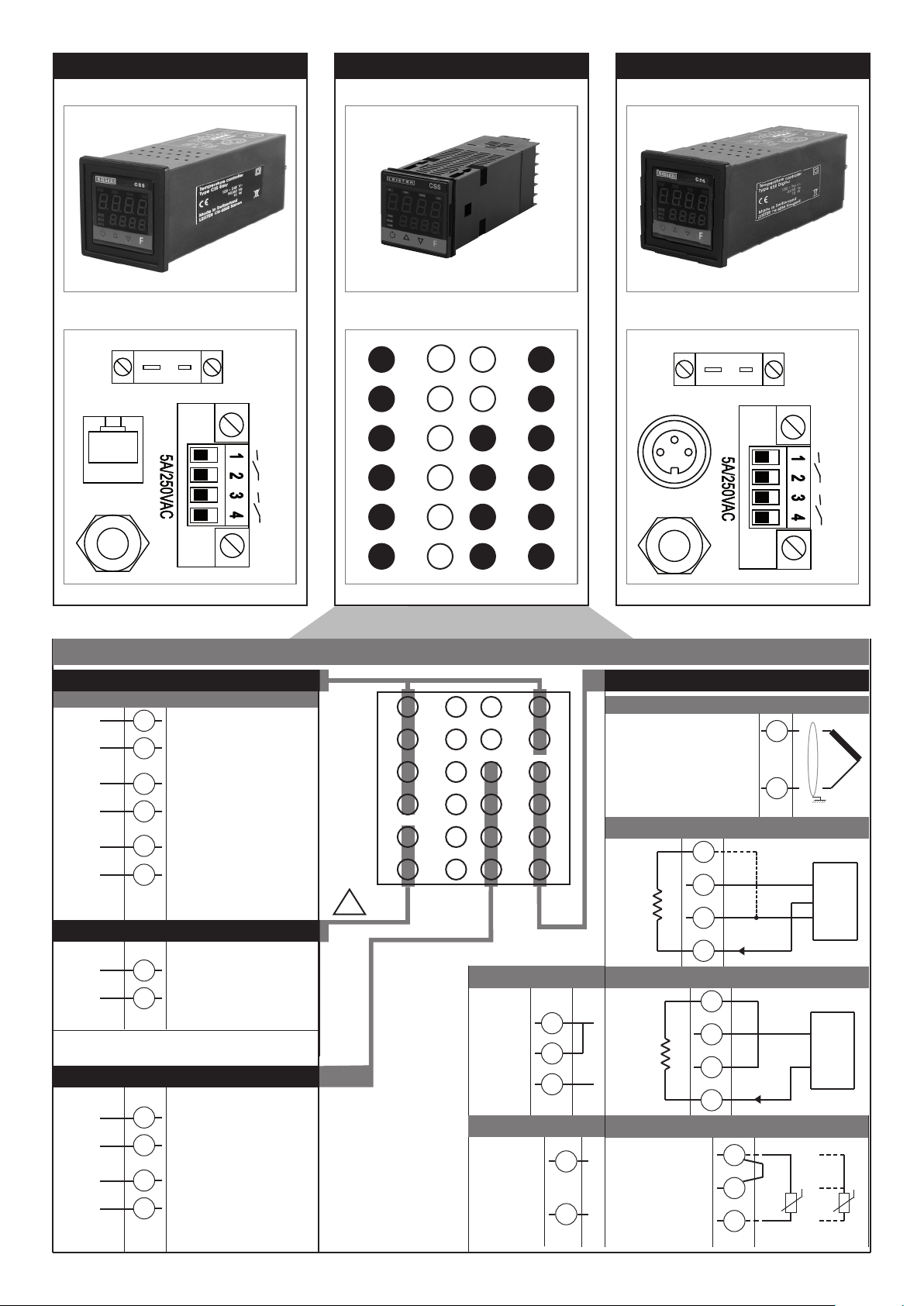
CSS CSS EASY KSR DIGITAL
16
TC
K
+
NiCr-Ni
Leister
I/O
Line
Alarm output 1 + 2 / Logic output
Configurable output
-
Out2
+
Out1
Out3
19
- Logic 24V, 10V zu 20mA
20
21
- Relais 5A zu 250Vac/30Vdc
(Alarm output 1)
22
6
- Relais 5A zu 250Vac/30Vdc
(Alarm output 2)
5
Power Supply
PWR
~
~
23
100 ... 240 VAC ± 10%
24
outputs
+
OUTPWR
-
-
Out4
+
9
- Feeding voltage 24 VDC for LeisterSYSTEM -Elektronik
10
11
- Output signal 4 – 20 mA
(0 – 20 mA / 0 – 10 VDC)
12
Out 1
Out 3
19
20
21
22
23
24
18
17
16
15
14
13
7
8
9
10
11
12
6
5
4
3
2
1
Connector pin assignment CSS
19
20
21
22
23
24
18
17
16
15
14
13
7
8
9
10
11
12
6
5
4
3
2
1
!
• Linear signal (I)
Linear
input in dc
current
20mA,
Ri = 50Ω
• Linear signal (V)
Linear input in dc
voltagel
60mV, 1V
Ri > 1MΩ
5V, 10V
Ri > 10KΩ
4
2
1
2
1
Leister I/O
Line
Available thermocouples:
J, K, R, S, T
(B, E, N, L, U, G, D, C custom
linearization is available)
- Observe polarities
- For extensions, use the correct
compensating cable for the type of
TC used
• Linear input for 3-wire transmitter
Ri = 50Ω
• Linear input for 3-wire transmitter
-
+
-
+
Ri = 50Ω
Use wires of adequate
diameter
(min. 1mm2)
PT100, JPT100,
PTC, NTC
TC
K
+
NiCr-Ni
Inputs
• TC
Connect at 20mA input
4
VT
+ 24V o 15V
3
-
2
+
1
4
+ 24V o 15V
VT
3
-
2
4...20mA
+
1
• Pt100 / PTC / NTC
3
2
1
PTC / NTC / Pt100
2
1
2 leiter
+
S
-
+
-
T
Out 1
Out 3
-
+
T
Pt100 3 wires
16
Page 17
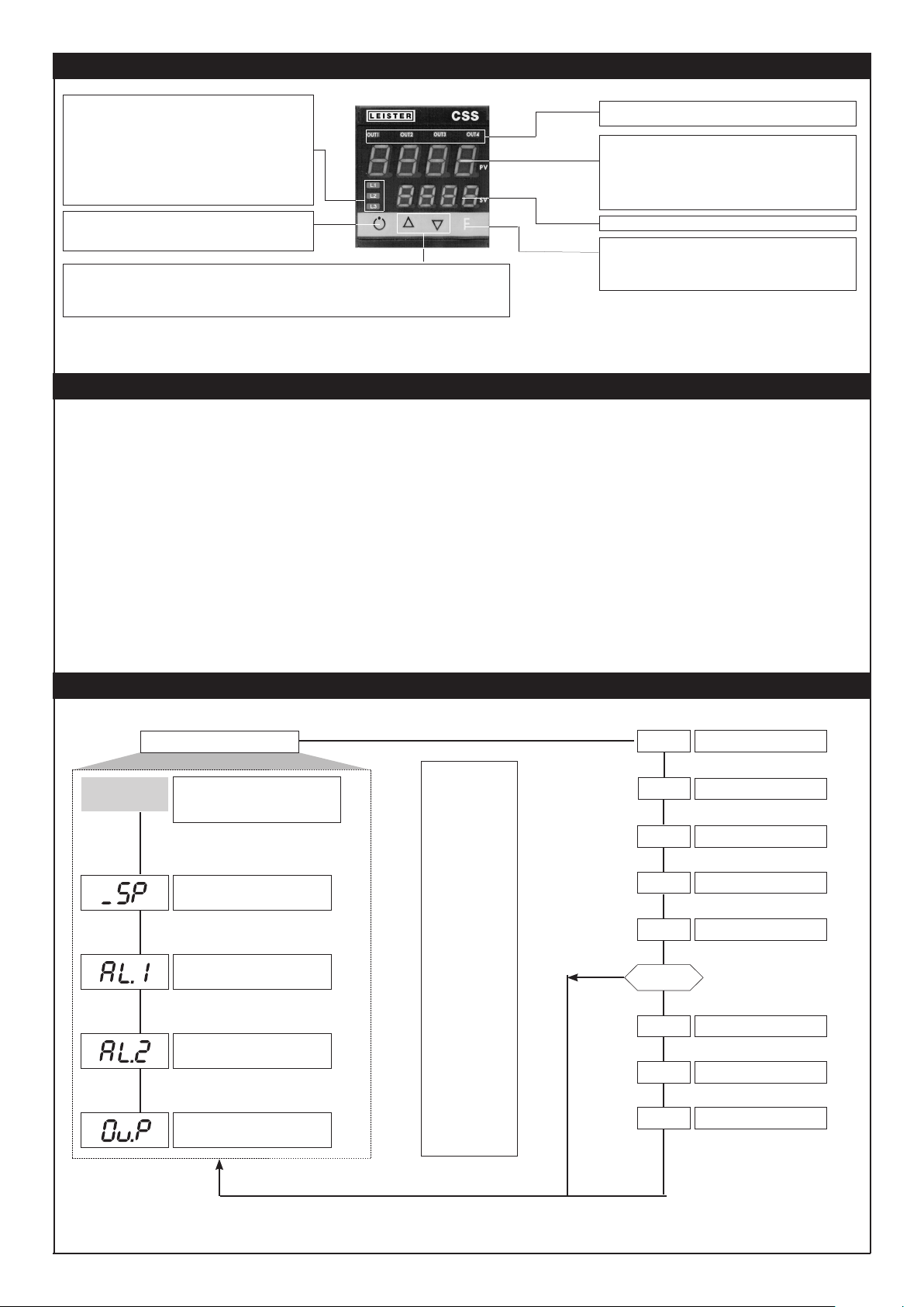
DESCRIPTION OF FACEPLATE
Indicates modes of operation
L1 MAN/AUTO = OFF (automatic control)
L2 SET SETPONT1/2 = OFF (IN1 = OFF - local Setpoint 1) ON
L3 SELFTUNING = ON (enabled Self)
Active only when PV display visualises the process variable
Press to increment (decrement) any numerical parameter •• Increment (decrement) speed is proportional to time key stays pressed
•• The operation is not cyclic: once the maximum (minimum) value of a field is reached, the value will not change even if the key
remains pressed.
Function indicator
ON (manual control)
(IN1 = ON - local Setpoint 2)
OFF (disabled Self)
“Auto/Man” key
Automatic/Manual adjustment selection
“Inc” and “Dec” key
Indication of output states
OUT 1 (AL 1); OUT 2 (Main); OUT 3 (AL 2); OUT 4
PV Display: Indication of process variable
Error Indication: LO, HI, Sbr, Err
LO = the value of process variable is < di LO_S
HI = the value of process variable is > di HI_S
Sbr = faulty sensor or input values higher than max. limits
Err = PT100 third wire opened for PT100, PTC or input values lower than min.
Gives access to the various configuration phases •• Confirms change of
set parameters and browses next or previous parameter (if Auto/Man key
is pressed)
limits (i.e.: TC wrong connection)
SV display: Indication of setpoint
Function key
F
SOFTWARE ADJUSTMENT
The temperature regulator is supplied by Leister Technologies AG with pre-programmed default settings.
These settings can be adjusted by the user if required (temperature input, control behaviour, etc.).
The values of the default settings are noted under the relevant menu item and apply to all CSS EASY and CSS.
KSR-DIGITAL have type-specific settings that can be requested from Leister Technologies AG.
P.V. / S.V.
Default: 650
Default: 650
PROGRAMMING and CONFIGURATION
LEVEL 1 MENU
P.V. / S.V.
Process variable (PV display)
Work Setpoint (SV display) or control output value
with controller in manual
Nominal value
Alarm value 1
Alarm value≤ 2
Control output value (in %)
Release the F key to
select the displayed
menu
Hold the F key down to
exit the menu.
Keep the F key pressed
to scroll the menus
Press the Auto/Man and
F key to go back in the
menu.
Keep F + Auto/Man keys
pressed for 2 sec. on any
menu to go immediately
to level 1 display
Pressing the Auto/Man
+ F keys on any menu
immediately returns
you to the previous
parameter.
INF
CFG
InP
Out
PAS
NO
PAS = 99
Pro
Hrd
U.CA
Information display
Custom menu
Input settings
Output settings
Password
Protection code
Hardware configuration
User calibration
N.B.: Once a particular configuration is entered, all unnecessary parameters are no longer displayed
17
17
Page 18
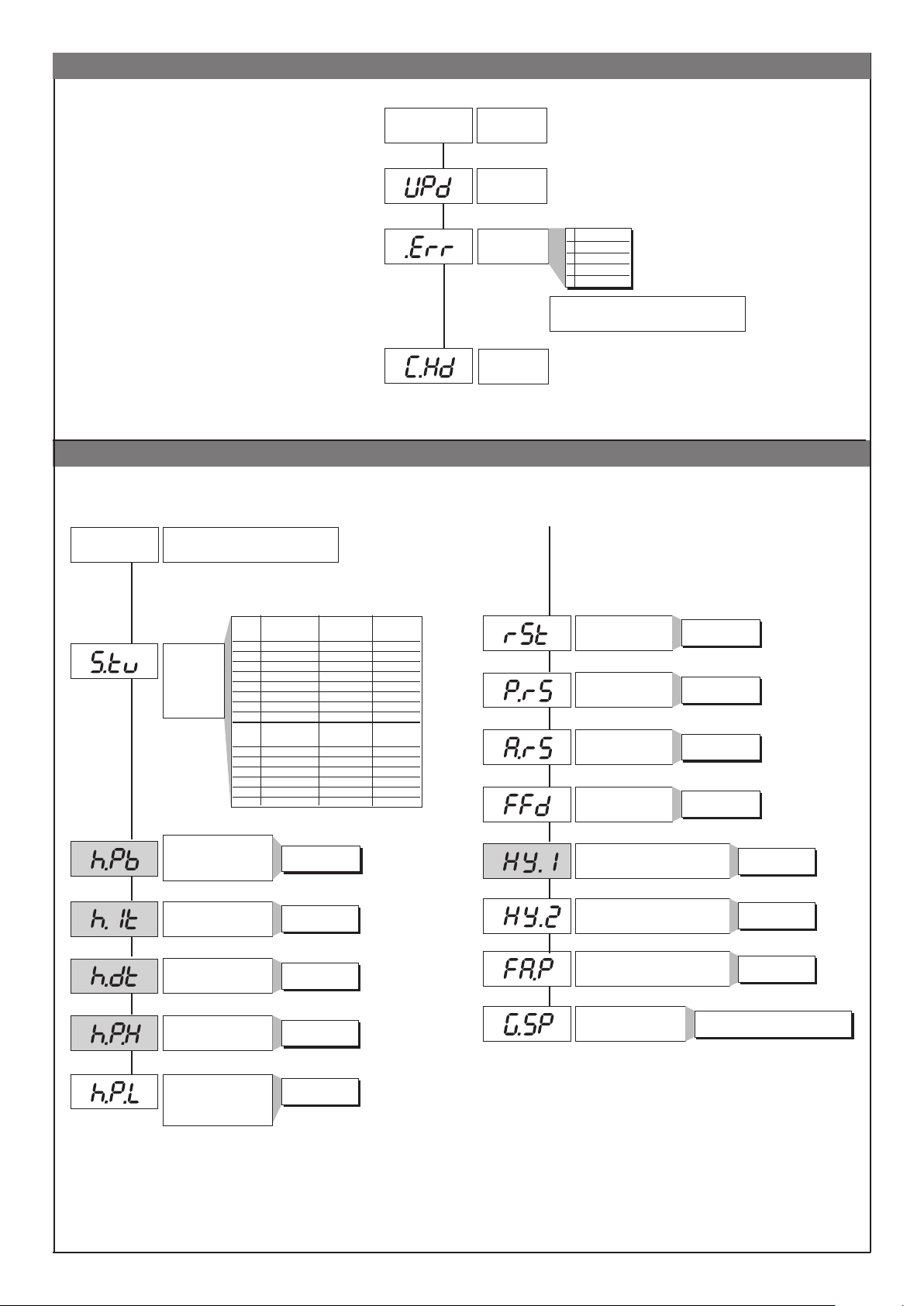
Information menu
CFG
Regelparameter
Default: 3.10
Default: 4
Default: 213
INF
CFG menu
Informations-
menu
Software-Version
Error display
Configuration hrd
0 No Error
1 Lo
2 Hi
3 ERR
4 SBR
+8 error OUT2 card recognition
+16 error OUT3 card recognition
Default: 0
Default: 30
Default: 0.2
Default: 0.01
Default: 100
Default: 0
S.tun Continuous Sel-ftuning Softstart
autotuning
0 NO NO NO
1 YES NO NO
Enabling
self-tuning,
autotuning,
softstart
Proportional band for heating
or hysteresis in regulation
Integral time for heating
Derivative time for heating
Maximum power limit for
Minimum power limit
(not available for double heat/
2 NO YES NO
3 YES YES NO
4 NO NO YES
5 YES NO YES
6 - - 7 - - -
S.tun Autotuning Selftuning Softstart
one shot
8* WAIT NO NO
9 GO NO NO
10* WAIT YES NO
11 GO YES NO
12* WAIT NO YES
13 GO NO YES
ON/OFF
heating
for heating
cool action)
0 ... 999.9% v.Ew.
0.00 ... 99.99 min
0.00 ... 99.99 min
0.0 ... 100.0%
0.0 ... 100.0%
Default: 0
Default: 0
Default: 0
Default: 0
Default: -1
Default: -1
Default: 0
Default: 0
Manual reset
Reset power -100.0 ... 100.0%
Antireset
Feedforward
Alarm 1 hysteresis
Alarm 2 hysteresis
Power output in fault condition
(when probe is faulty)
Set gradient
(see applicable note)
-999 ... 999
scale points
0 ... 9999
scale points
-100.0 ... 100.0%
± 999
scale points
± 999
scale points
-100.0 ... 100.0%
ON / OFF
0.0...999.9 digit/min.
(digit / sec see SP.r)
18
18
Page 19
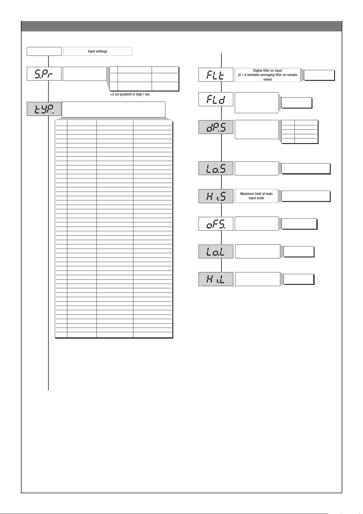
InP
Input settings
+2 set gradient in digit / sec
Digital filter on input
(if = 0 excludes averaging filter on sample
value)
Maximum limit of main
input scale
InP Menu
Default: 0
Default: 2
Def. remote setpoint
Probe type, signal, enable custom linearization,
Type Probe type without decimal point with decimal point
Sensore: TC
0 TC J °C 0/1000 0.0/999.9
1 TC J °F 32/1832 32.0/999.9
2 TC K °C 0/1300 0.0/999.9
3 TC K °F 32/2372 32.0/999.9
4 TC R °C 0/1750 0.0/999.9
5 TC R °F 32/3182 32.0/999.9
6 TC S °C 0/1750 0.0/999.9
7 TC S ° F 32/3182 32.0/999.9
8 TC T °C -200/400 -199.9/400.0
9 TC T °F -328/752 -199.9/752.0
28 TC CUSTOM CUSTOM
29 TC CUSTOM CUSTOM
30 PT100 °C -200/850 -199.9/850.0
31 PT100 °F -328/156 2 -199.9/999.9
32 JPT100 °C -200/600 -199.9/600.0
33 JPT100 °F -328/1112 -199.9/999.9
34 PTC °C -55/120 -55.0/120.0
35 PTC °F -67/248 -67.0/248.0
36 NTC °C -10/70 -10.0/70.0
37 NTC °F 14/158 14.0/158.0
38 0...60 mV -1999/9999 -199.9/999.9
39 0...60 mV Custom scale Custom scale
40 12...60 mV -1999/9999 -199.9/999.9
41 12...60 mV Custom scale Custom scale
42 0...20 mA -1999/9999 -199.9/999.9
43 0...20 mA Custom scale Custom scale
44 4...20 mA -1999/9999 -199.9/999.9
45 4...20 mA Custom scale Custom scale
46 0...10 V -1999/9999 -199.9/999.9
47 0...10 V Custom scale Custom scale
48 2...10 V -1999/9999 -199.9/999.9
49 2...10 V Custom scale Custom scale
50 0...5 V -1999/9999 -199.9/999.9
51 0...5 V Custom scale Custom scale
52 1...5 V -1999/9999 -199.9/999.9
53 1...5 V Custom scale Custom scale
54 0...1 V -1999/9999 -199.9/999.9
55 0...1 V Custom scale Custom scale
56 200mv..1V -1999/9999 -199.9/999.9
57 200mv..1V Custom scale Custom scale
58 Cust10 V-20mA -1999/9999 -199.9/999.9
59 Cust10 V-20mA Custom scale Custom scale
60 Cust 60mV -1999/9999 -199.9/999.9
61 Cust 60mV Custom scale Custom scale
62 PT100-JPT CUSTOM CUSTOM
63 PTC CUSTOM CUSTOM
64 NTC CUSTOM CUSTOM
Val. Type of remote setpoint Absolute Relative
0 Digital Absolute
(from serial line)
1 Digital Reletive to
(from serial line) local setpoint
and main input scale
Default: 0.1
Default: 0.5
Default: 0
Default: 0
Default: 1300
Default: 0
Default: 0
Default: 650
Digital filter on input display
Decimal point position for
input scale
Minimum limit of main input
scale
Oset correction
of main input
Lower limit for setting SP and
absolute alarms
Upper limit for setting SP and
absolute alarms
0.0 ... 20.0 s
0 ... 9.9
scale points
dP_S Format
0 xxxx
1 xxx.x
2 xx.xx (*)
3 x.xxx (*)
(*) not available for TC, RTD, PTC
and NTC scales
min...max input range selected
in tyP
min...max input range selected
in tyP
-999 ... 999
scale points
Lo.S ... Hi.S
Lo.S ... Hi.S
For custom linearization:
- LO signal is generated with variable below Lo.S or at minimum calibration value
- HI signal is generated with variable above Lo.S or at maximum calibration value
19
19
Page 20
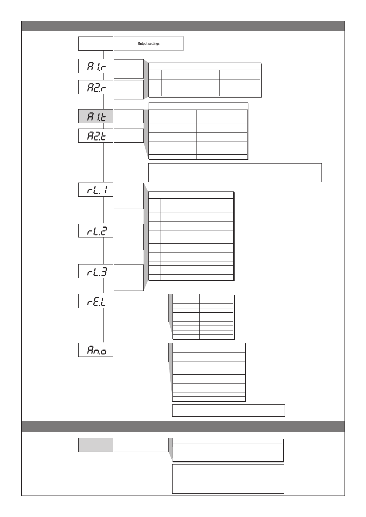
Out
Output settings
Out Menu
Default: 0
Default: 0
Default: 0
Default: 0
Default: 2
Default: 5
Default: 3
Default: 0
Default: 5
Select reference
signal for
alarm 1
Select reference
signal for
alarm 2
Alarm type 1
Alarm type 2
Out 1
Allocation of
reference signa
Out 2
Allocation of
reference signal
Out 3
Allocation of
reference signal
Fault action (sets state in case of
Assignment of signal or reference
AL.x.r Variable to be compared Reference setpoint
0 PV (Process variable) AL
1 SSP (active setpoint) AL (only absolute)
2 PV (process variable) AL (only relative and
referred to SP1 with
multiset function)]
AL.x.t Direct (high limit) Absolute or Normal
Inverse (low limit) relative to
active setpoint (window)
0 direct absolute normal
1 inverse absolute normal
2 direct relative normal
3 inverse relative normal
4 direct absolute
5 inverse absolute
6 direct relative
7 inverse relative
+8 to disable on power up until first interception
+16 to latch alarm
+ 32 Hys becomes delay time when alarm trips (0...999 sec.) (excluding symmetrical absolute)
+ 64 Hys becomes delay time when alarm trips (0...999 min.) (excluding symmetrical absolute)
Val Function of main output relay/logic (OUT1)
0 HEAT (control output for heating)
1 COOL (control output for cooling)
2 AL1 - alarm 1
3 AL2 - alarm 2
4 AL3 - alarm 3
5 AL.HB - alarm HB
6 LBA - alarm LBA
7 IN1 - repetition of logic input
8 Repeat but key (if but = 8)
9 AL1 or AL2
10 AL1 or AL2 or AL3
11 AL1 and AL2
12 AL1 and AL2 and AL3
13 AL1 or ALHB
14 AL1 or AL2 or ALHB
15 AL1 and ALHB
16 AL1 and AL2 and ALHB
+ 32 for denied logic level at output, except codes 0…1 with continuous output
probe fault)
Err, Sbr
Out W
value
AL.1.r, AL.2.r
AL.1.t, AL.2.t
Symmetrical
symmetrical
symmetrical
symmetrical
symmetrical
rL.o.1, rL.o.2, rL.o.3, rL.o.4
_rEL. Alarm Alarm Alarm
1 2 3
0 OFF OFF OFF
1 ON OFF OFF
2 OFF ON OFF
3 ON ON OFF
4 OFF OFF ON
5 ON OFF ON
6 OFF ON ON
7 ON ON ON
Val Reference value
0 PV - process variable
1 SSP - active setpoint
2 SP - local setpoint
3 4 Deviation (SSP-PV)
5 HEAT (*)
6 COOL (*)
7 AL1 (alarm point)
8 AL2 (alarm point)
9 AL3 (alarm point)
10 11 Value acquired from serial line (*)
16 for code 0 if input is in error status Err – Sbr output assumes minimum
trimming value.
Prot menu (PAS)
Pro
Protection code
(PAS 99)
20 20
Prot Display Modification
0 SP, In2, alarms, OuP, INF SP, alarms
1 SP, In2, alarms, OuP, INF SP
2 SP, In2, OuP, INF
+ 4 to disable InP, Out
+ 8 to disable CFG, Ser,
+ 16 to disable SW “power-up - power down”
+ 32 disable manual power latching
+ 64 to disable manual power modification
+128 enables full configuration
Page 21
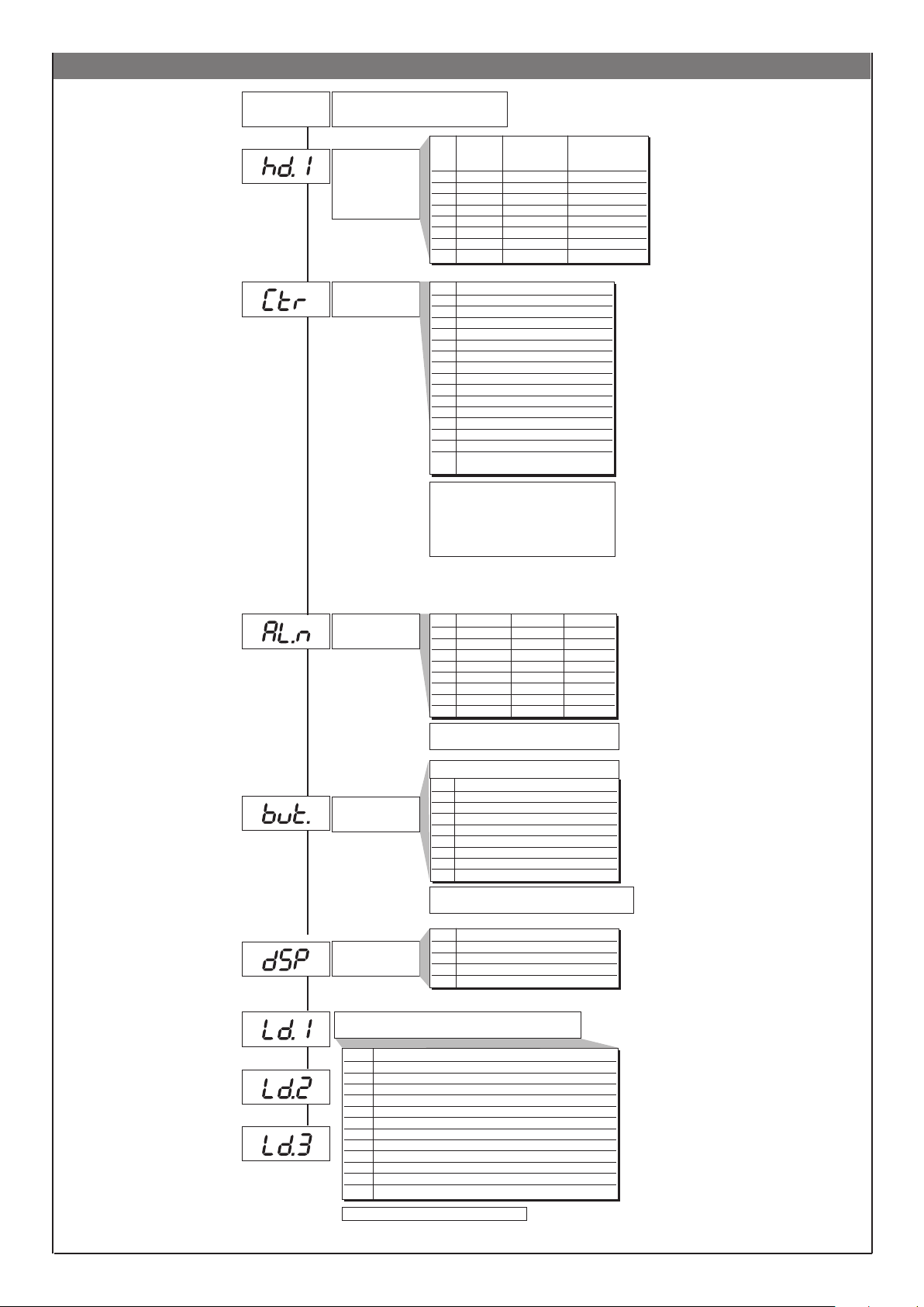
Hrd menu
Default: 0
Default: 70
Hrd
Hardware configuration
Enable multiset
instrument control
by serial
Control type
Val Multiset Reversed LED Instrument
(2 SP) state control by
serial
0
1 x
2 x
3 x x
4 x
5 x x
6 x x
7 x x x
Val Control type
0 P heat
1 P cool
2 P heat / cool
3 PI heat
4 PI cool
5 PI heat / cool
6 PID heat
7 PID cool
8 PID heat / cool
9 ON-OFF heat
10 ON-OFF cool
11 ON-OFF heat / cool
12 PID heat + ON-OFF cool
13 ON-OFF heat + PID cool
14 PID heat + cool with relative gain
(see C.MEd parameter)
Selection of derivative action sampling time:
+ 0 sample 1 sec.
+ 16 sample 4 sec.
+ 32 sample 8 sec.
+ 64 sample 240 msec.
Default: 3
Default: 1
Default: 0
Select number of
enabled alarms
Function of M/A keys
Definition der
Anzeigefunktion SV
Note: LbA alarm is not enabled with ON/OFF type
control
AL.nr Alarm 1 Alarm 2 Alarm 3
0 disabled disabled disabled
1 enabled disabled disabled
2 disabled enabled disabled
3 enabled enabled disabled
4 disabled disabled enabled
5 enabled disabled enabled
6 disabled enabled enabled
7 enabled enabled enabled
+ 8 to enable HB alarm
+ 16 to enable LBA alarm
b u t t
0 No function (key disenabled)
1 MAN / AUTO controller
2 LOC / REM
3 HOLD
4 Alarms memory reset
5 SP1 / SP2 Selection
6 Start / Stop selftuning
7 Start / Stop autotuning
8 Set / Reset outputs Out 1... Out 4
+ 16 disables the „back menu“ function (Auto/Man + F
keys) in the configuration menus
diSP Lower display (SV) function
0 SSP - setpoint enabled
1 InP.2 - aux input
2 Control output value
3 Deviation (SSP - PV)
Default: 1
Default: 10
Default: 20
Function of LEDs
Val. Function
0 none
1 MAN/AUTO controller
2 LOC / REM
3 HOLD
4 Selftuning enabled
5 Autotuning enabled
6 IN1 repetition
7 Enable serial dialogue
8 Error present
9 Softstart running
10 SP1...SP2 Indication
11 Set point gradient running
+ 16 LED flashes if active
2121
Page 22
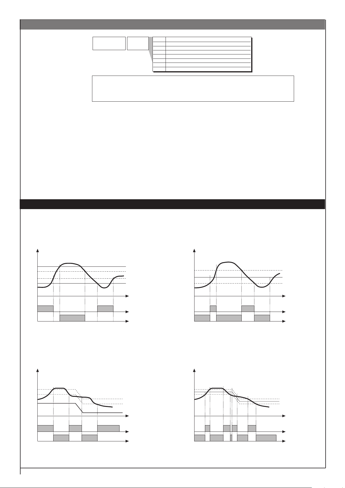
U.CAL menu
Val Function
1 Analogue output (1)
2 Input 1 – custom 10V / 20mA
3 Input 1 - custom 60mV
4 Custom PT100 / J PT100
5 Custom PTC
6 Custom NTC
7 Input 2 - custom TA (2)
Default: 0
U.CA
User
calibration
(1) The analog output in 20mA is calibrated with accuracy higher than 0.2 % f.s.; calibrate when
converting to 10V output.
(2) In the absence of calibration, accuracy is higher than 1% f.s.; calibrate only if higher
accuracy is required.
ALARMS
Normal absolute alarm Symmetrical absolute alarm
AL2
AL1
alarm 1
alarm 2
For AL1 = reverse absolute alarm (low) with positive Hyst1, AL1 t = 1
(*) = OFF if disabled on power-up
For AL2 = direct absolute alarm (high) with negative Hyst2, AL2 t = 0
SP+AL1
(*)
Deviation alarm Symmetrical deviation Alarm
SP
AL2 + Hyst2
AL1 + Hyst1
time
Hyst1
AL1 + [ Hyst1 * ]
AL1
AL1 - [ Hyst1* ]
time
reverse alarm
direct alarm
For AL1 = symmetrical Lo absolute alarm with Hyst1, AL1 t = 5
For AL1 = symmetrical Hi absolute alarm with Hyst1, AL1 t = 4
* Minimum hysteresis = 2 scale points
SP+AL1
SP
SP-AL1
reverse
alarm
direct
alarm
For AL1 = Lo deviation alarm with negative Hyst 1, AL1 t = 3
For AL1 = Hi deviation alarm with negative Hyst 1, AL1 t = 2
time
reverse alarm
direct alarm
For AL1 = Symmetrical Lo deviation alarm with Hyst 1, AL1 t = 7
For AL1 = Symmetrical Hi deviation alarm with Hyst 1, AL1 t = 6
time
22 22
Page 23
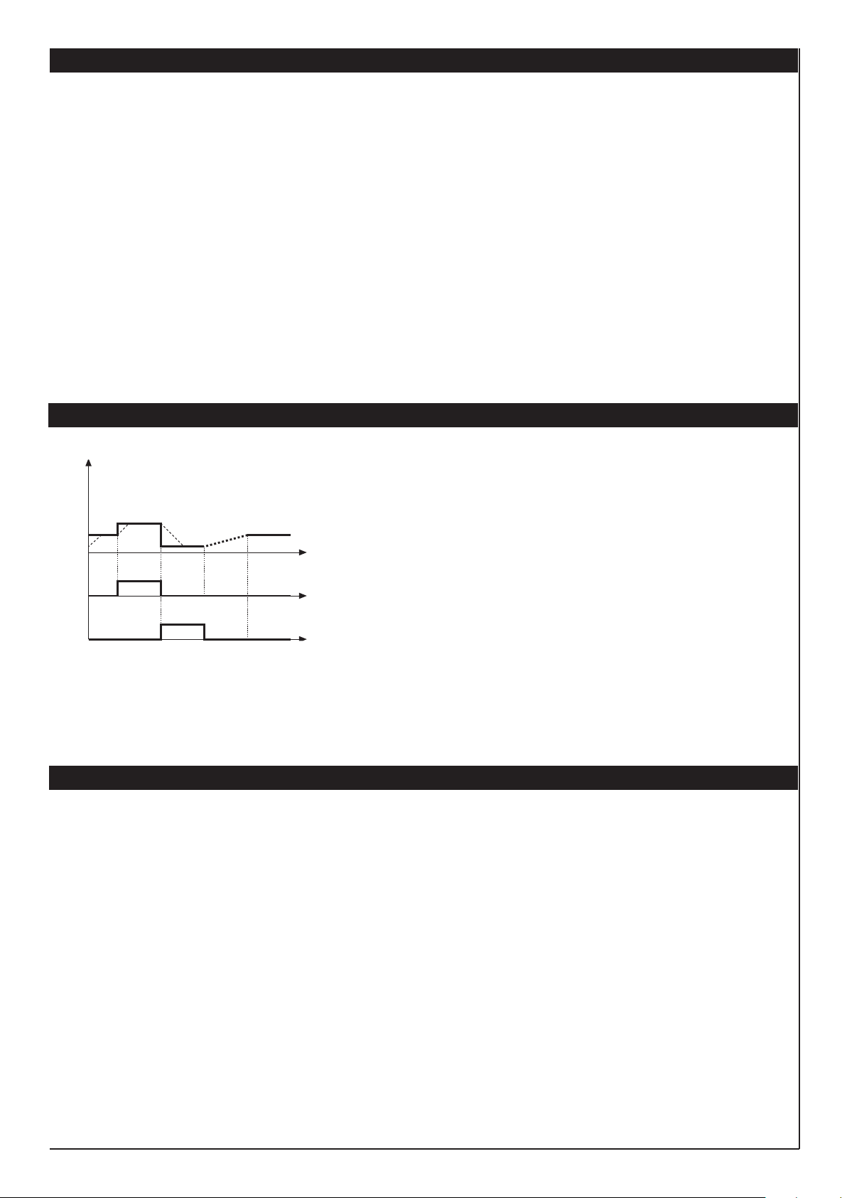
CONTROL ACTIONS
Proportional Action:
action in which contribution to output is proportional to deviation at input (deviation = dierence between controlled variable and setpoint).
Derivative Action:
action in which contribution to output is proportional to rate of variation input deviation.
Integral Action:
action in which contribution to output is proportional to integral of time of input deviation.
Influence of Proportional, Derivative and Integral actions on response of process under control
* An increase in P.B. reduces oscillations but increases deviation.
* A reduction in P.B. reduces the deviation but provokes oscillations of the controlled variable (the system tends to be unstable if P.B. value is too low).
* An increase in Derivative Action corresponds to an increase in Derivative Time, reduces deviation and prevents oscillation up to a critical value of Derivative Time,
beyond which deviation increases and prolonged oscillations occur.
* An increase in Integral Action corresponds to a reduction in Integral Time, and tends to eliminate deviation between the controlled variable and the setpoint when
the system is running at rated speed.
If the Integral Time value is too long (Weak integral action), deviation between the controlled variable and the setpoint may persist.
Contact GEFRAN for more information on control actions.
MULTISET FUNCTION, SET GRADIENT
SP
The gradient function is always enabled.
You can select between setpoint 1 and setpoint 2 with the faceplate key or with digital
The multiset function is enabled in hd.1.
input.
You can display the setpoint 1-2 selection by means of LED.
SET GRADIENT: if set to ≠0, the setpoint is assumed equal to PV at power-on and auto/
man switchover. With gradient set, it reaches the local setpoint or the one selected.
t
SP1
SP2
SPrem
SP1
(*)
Every variation in setpoint is subject to a gradient.
IN1
ON
The set gradient is inhibited at power-on when self-tuning is engaged.
t
If the set gradient is set to ≠0, it is active even with variations of the local setpoint,
settable only on the relative SP menu.
LOC/REM
ON
(*) if the set gradient is set
The control setpoint reaches the set value at the speed defined by the gradient.
t
SOFTWARE ON / OFF SWITCHING FUNCTION
How to switch the unit OFF: hold down the “F” and “Raise” keys simultaneously for 5 seconds to deactivate the unit, which will go to the OFF state while keeping
the line supply connected and keeping the process value displayed. The SV display is OFF.
All outputs (alarms and controls) are OFF (logic level 0, relays de-energized) and all unit functions are disabled except the switch-on function and digital
communication.
How to switch the unit ON: hold down the “F” key for 5 seconds and the unit will switch OFF to ON. If there is a power failure during the OFF state, the unit will
remain in OFF state at the next power-up (ON/OFF state is memorized).
The function is normally enabled, but can be disabled by setting the parameter Prot = Prot +16. This function can be assigned to a digital input (d.i.G) and excludes
deactivation from the keyboard.
2323
Page 24
F
Instructions d‘utilisation
(Traduction de la notice d’utilisation originale)
Instructions d’utilisation à lire trés attentivement avant mise en
marche et à conserver pour besoins ultérieurs
Leister CSS EASY / CSS / KSR DIGITAL
Régulateur de température
VERSION LOGICIEL 3.10
Édition instructions d’utilisation 05.2008
Avertissement
Danger de mort à l’ouverture de l’appareil, car des composants et des liaisons sous tension sont
découverts. Avant d‘ouvrir l‘appareil, débranchez-le du secteur sur tous les pôles.
Vorsicht
100
230
Maintenance et réparation
Les réparations doivent être réalisées exclusivement par les SAV Leister compétents. Ils garantissent un service de réparation
approprié et fiable avec des pièces d’origine, conformément aux schémas de câblage et aux listes des pièces de rechange.
Garantie
L’appareil est couvert par une garantie de base d’un (1) an à compter de la date d’achat (prouvée grâce à la facture ou au bon de
livraison). Une livraison de remplacement ou des réparations permettent de corriger les dommages survenus.
•
Toute autre prétention est exclue, sous réserve des dispositions légales applicables.
• Les dommages imputables à l’usure naturelle, à une surcharge ou à une manipulation non conforme sont exclus de la
garantie.
Toute prétention est exclue pour les appareils qui ont été transformés ou modifiés par l’acheteur.
•
Conformité
Leister Technologies AG, Galileo-Strasse 10, 6056 Kaegiswil/Suisse
confirme que ce produit correspond, en ce qui concerne la conception et le modèle type dans la version commercialisée par notre
entreprise, aux réglementations figurantdans les directives européennes désignées ci-dessous.
Directives: 2004/108, 2006/95
Normes harmonisées:
La tension nominale indiquée sur l’appareil doit correspondre à la tension du secteur.
Protégez l’appareil de l’humidité et de la pluie.
EN 61326-1:2013, EN 61010-1:2010, EN 50581:2012
Kaegiswil, 17.11.2017
Bruno von Wyl, CTO
Elimination de déchets
Les appareils électroniques, les accessoires et les emballages doivent être recyclés en respectant l’environnement. Pour les
pays de l’UE uniquement: ne pas jeter les appareils électroniques avec les déchets ménagers!
2424
Christoph Baumgartner, GM
Page 25
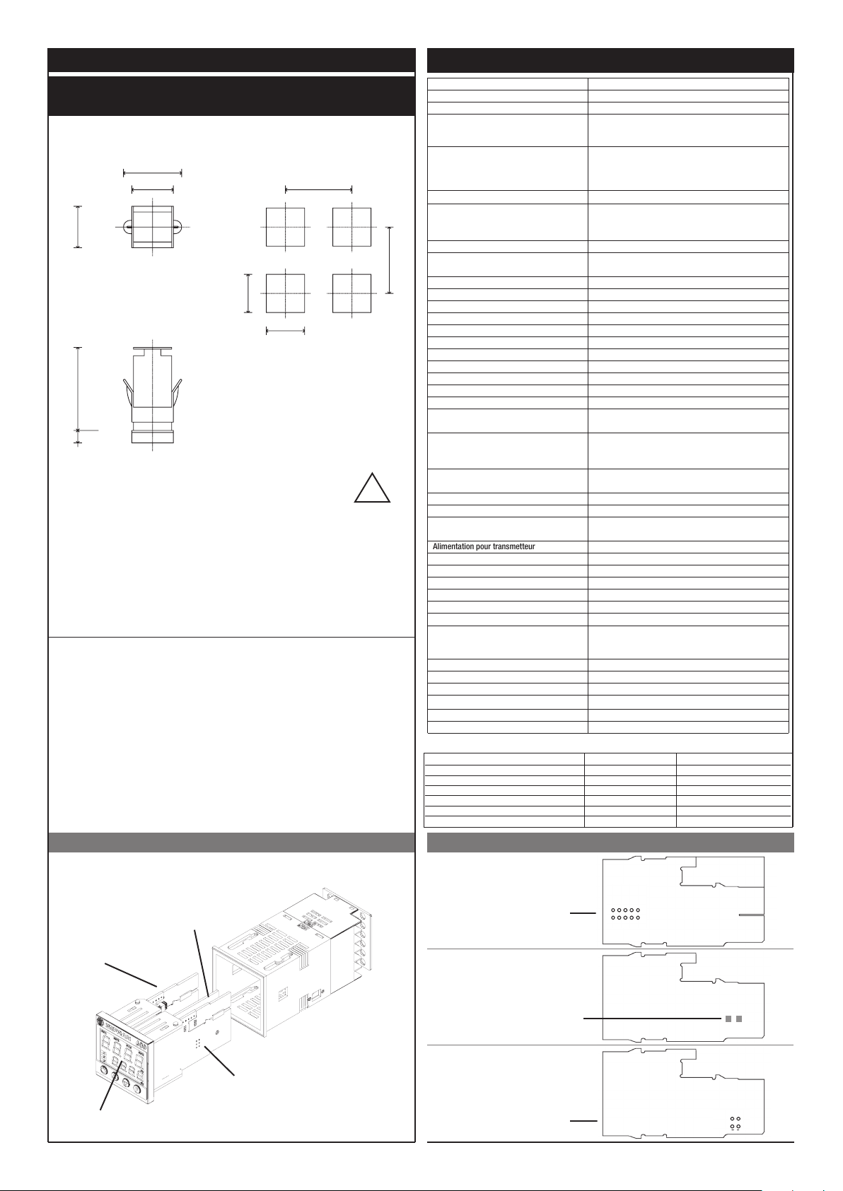
INSTALLATION
Alimentation pour transmetteur
• Dimensions d’encombrement et de découpe;
montage sur panneau
63
48
45
99
10
70
70
45
!
Pour une installation
correcte, lire les
instructions contenues
dans ce manuel
Bloquer les instruments à l’aide de la patte prévue à cet eet avant d’eectuer les raccordements électriques.
Pour monter deux instruments, ou plus, côte à côte, respecter pour la découpe les mesures indiquées sur le
dessin.
MARQUAGE CE: Conformité CEM (compatibilité électromagnétique) dans le respect de la Directive 89/336/
CEE par référence aux Normes génériques CEI- EN61000-6-2 (immunité en milieu industriel) et EN50081-1
(émission en milieu résidentiel). Conformité BT (basse tension) dans le respect de la Directive 73/23/CEE
modifiée par la Directive 93/68.
Entretien: L’appareil est sans entretien.
Ne pas nettoyer le boîtier avec des solvants dérivés d’hydrocarbures (trichloréthylène, essence, etc.). L’emploi
de ces solvants compromettrait la fiabilité mécanique de l’instrument. Pour nettoyer les parties extérieures en
plastique, utiliser un chion propre humecté d’alcool éthylique ou d’eau.
ASSISTANCE TECHNIQUE: Leister met à disposition un service d’assistance technique.
Montage sur panneau
CARACTÉRISTIQUES TECHNIQUES
Acheur 2 x 4 digits, vert, hauteur chires 10 et 7 mm
Touches 4 du type mécanique (Man/Aut, HAUT, BAS, F)
Précision
Entrée principale (filtre numérique
programmable)
Type TC Thermocouples
(ITS90)
Erreur comp. soudure froide
Type RTD (échelle programmable dans la
plage indiquée, avec ou sans point décimal)
(ITS90)
Résistance maxi de ligne pour RTD
Type PTC / Type NTC 990Ω, 25°C / 1KΩ, 25°C
Sécurité
Sélection °C/°F configurable à l’aide des touches
Plage échelles linéaires -1999 … 9999 point décimal programmable
Actions de contrôle PID, Autoréglage, ON-OFF
pb - dt - it 0,0...999,9 % - 0,00...99,99 min - 0,00...99,99 min
Action
Sorties de contrôle ON / OFF, continue
Limitation puissance maxi chaud / froid 0,0...100,0 %
Temps de cycle 0...200 s
Type de sortie principale relais, logique, continue (0....10 V / 4...20 mA)
Softstart (rampe de démarrage) 0,0...500,0 min
Programmation puissance de sécurité
Fonction arrêt
Alarmes configurables
Masquage alarmes
Type de contact relais NO (NF), 5A, 250V/30Vdc cosϕ=1
Sortie logique pour relais statiques 24Vc.c. ±10% (10V min à 20mA)
Sortie Triac
Retransmission analogique 10 V/20 mA Rcharge maxi 500 Ω résolution 12 bits
Entrée logique
Interface série RS485, isolée
Débit en bauds 1200, 2400, 4800, 9600, 19200
Protocole Gefran CENCAL / MODBUS
Option entrée de courant T.A. 50mAac, 50/60Hz, Ri = 10Ω
Alimentation (type à découpage)
Protection façade IP65
Température de travail / stockage 0...50°C / -20...70°C
Humidité relative 20 ... 85%, sans condensation
Conditions environnementales de l‘utilisation pour l‘usage interne, altitude jusque à 2000m
Installation
Poids 160 g en version complète
La conformité CEM a été vérifiée avec les raccordements suivants
FONCTION TYPE DE CÂBLE LONGUEUR EMPLOYÉE
Câble d’alimentation 1 mm2 1 m
Fils sortie relais 1 mm2 3,5 m
Câble raccordement série 0,35 mm2 3,5 m
Fil raccordement T.I. 1,5 mm2 3,5 m
Capteur entrée thermocouple 0,8 mm2 compensé 5 m
Capteur entrée thermorésistance “PT100” 1 mm2 3 m
TC, RTD, PTC, NTC
60mV, 1V Ri≥1 MΩ; 5V, 10V Ri≥10KΩ; 20mA Ri=50 Ω
Temps d‘acquisition 120 ms
Type TC Thermocouples: J, K, R, S, T, (IEC 584-1,
CEI EN 60584-1,60584-2) Possibilité de linéarisation personnalisée
B, E, N, L GOST, U, G, D, C soyez disponible en employant la
linéarisation custom
DIN 43760 (Pt100), JPT100
20Ω
détection court-circuit ou rupture capteur, alarme LBA, alarme
HB
Maintient l’achage de PV (variable de process), possibilité de
désactivation
Jusqu’à 3 fonctions d’alarme associables à une sortie et
configurables du type: maxi, mini, symétriques, absolues/
asservies, LBA, HB
- exclusion à la mise en marche
- reset mémoire via les touches et/ou un contact
20...240Vac ±10%, 1A max
Snubberless, charge inductive et résistive I2t = 128A2s
15/24 V c.c., 30 mA maxi protection court-circuit
Ri = 4,7KΩ (24V, 5mA) ou par contact libre de potentiel
CPU
DISPLAY
OUT4
POWER
Carte POWER
Carte OUT4
S oen:
Strom-Ausgangssignal
S geschlossen
Spannung-Ausgangssignal
Carte CPU
Sélection signal sur
contact 3
Sélection tension
d’alimentation
transmetteur
Leiterplatten Aufbau des Instruments
15V
10V5V1,23V
24V
S
+VT
PT100
2525
Page 26
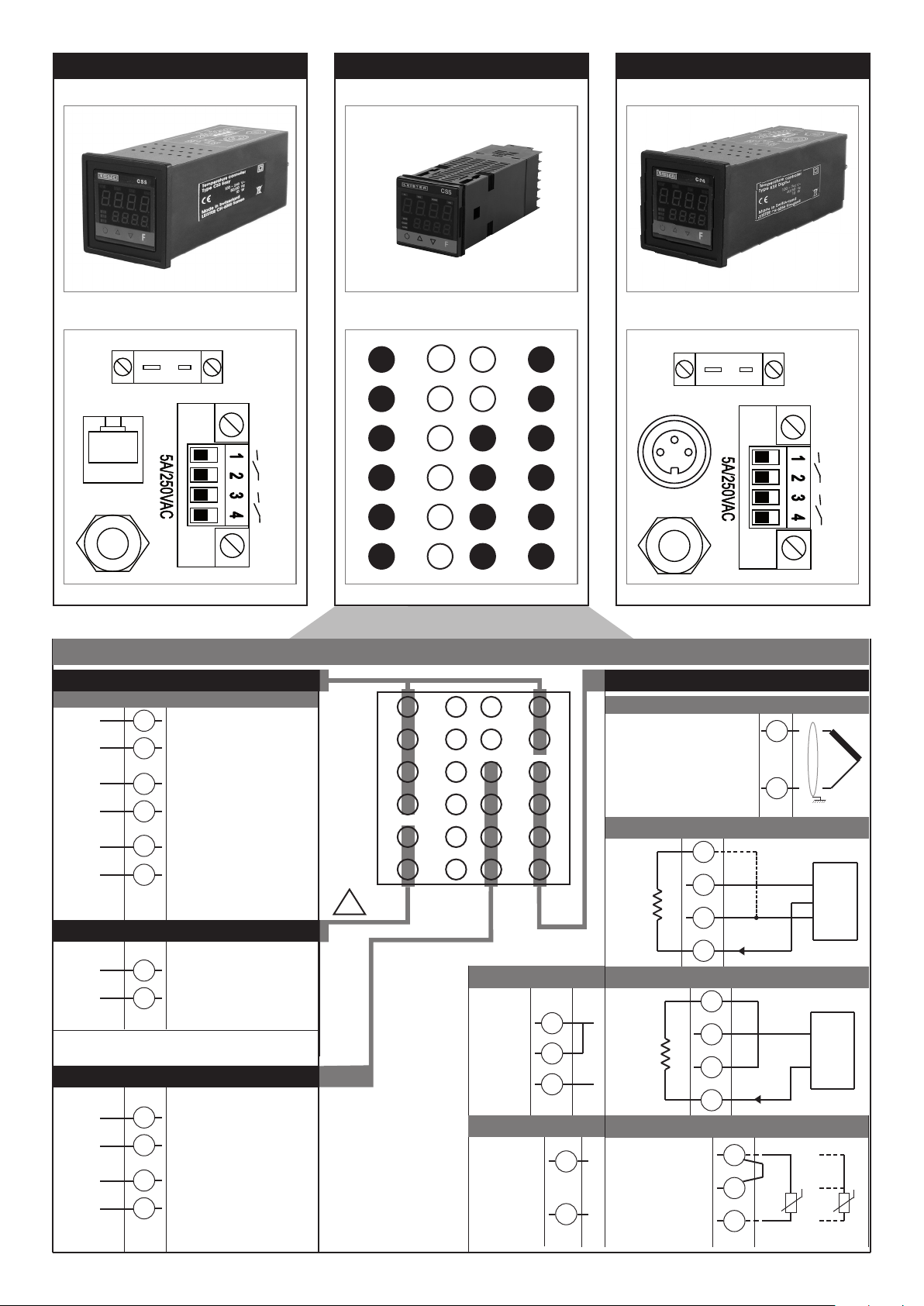
CSS CSS EASY KSR DIGITAL
Leister
I/O
Line
TC
K
NiCr-Ni
19
+
20
21
Out 1
Out 3
22
23
24
18
17
16
15
14
13
7
8
9
10
11
12
6
5
4
3
2
1
Leister I/O
Line
TC
K
NiCr-Ni
+
Out 1
Out 3
Connexions CSS
Sortie d‘alarme 1 + 2 / Sortie logique
Sorties d’emploi générique configurables par l’utilisateur
-
Out2
+
Out1
Out3
19
- Logique 24V, 10V à 20mA
20
21
- Relais 5A à 250Va.c./30Vc.c.
(Sortie d’alarme 1)
22
6
- Relais 5A
(Sortie d’alarme 2)
5
à 250Va.c./30Vc.c.
19
20
21
22
23
24
18
17
16
15
14
13
7
8
9
10
11
12
!
6
5
4
3
2
1
Thermocouples disponibles:
J, K, R, S, T (B, E, N, L, U, G, D, C la
linéarisation faite sur commande est
disponible)
- Respecter la polarité.
- Pour des extensions, utiliser un câble
compensé adapté au type de TC employé.
• Entrée linéaire avec transmetteur 3 fils
Ri = 50Ω
Alimentation
~
PWR
~
+
OUTPWR
-
-
Out4
+
2626
23
100 ... 240 VAC ± 10%
24
Sorties
9
- Tension d’alimentation 24 VDC
Leister-SYSTEM -électronique
10
11
- Le signal de sortie 4 – 20 mA
(0 – 20 mA / 0 – 10 VDC)
12
pour
• Entrée linéaire (I)
Entrée
linéaire en
courant
continu
20mA,
Ri = 50Ω
• Linearsignal (V)
Entrée linéaire en
tension continue
60mV, 1V
Ri > 1MΩ
5V, 10V
Ri > 10KΩ
• Entrée linéaire avec transmetteur 2 fils
-
4
2
+
1
-
2
+
1
Ri = 50Ω
Utiliser des fils d’une
section appropriée
(min. 1mm2)
PT100, JPT100,
PTC, NTC
Entrées
• TC
4
3
2
1
• Pt100 / PTC / NTC
Raccorder pour entrée 20 mA
VT
+ 24V o 15V
-
+
4
+ 24V o 15V
VT
3
-
2
4...20mA
+
1
3
2
1
PTC / NTC / Pt100
2 fils
-
+
+
S
-
+
-
T
T
Pt100 3 fils
2
1
Page 27
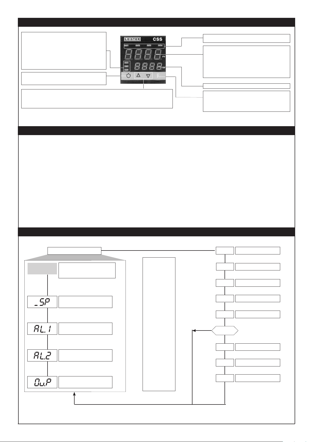
DESCRIPTION FAÇADE INSTRUMENT
Signalent le type de fonctionnement de l’instrument:
L1 MAN/AUTO = OFF (réglage automatique)
ON (réglage manuel)
L2 SETPONT1/2 = OFF (IN1= OFF - Consigne locale 1)
ON (IN1= ON - Consigne locale 2)
L3 SELFTUNING = ON (Self activé)
OFF (Self désactivé)
Active uniquement quand l’acheur PV visualise la mesure
Permettent d’incrémenter ou de décrémenter un quelconque paramètre numérique •• La vitesse d’incrémentation ou de décrémentation est proportionnelle
à la durée de la pression sur la touche •• L’opération n’est pas cyclique, c’est-à-dire qu’une fois qu’on a atteint le maximum ou le minimum d’une
Indicateurs de fonction:
Touche „Auto/Man“
Sélection réglage Automatique/Manuel:
Touches «HAUT» et «BAS»
plage de progr ammation, la fonc tion incrémentation/décrémentation se bloque même si on maintient la pression sur la touche.
Err = troisième fil interrompu pour PT100/PTC ou valeurs de
Permet d’accéder aux diverses phases de configuration •• Valide la modification des
paramètres programmés et passe au paramètre suivant ou précédent si on appuie en
même temps sur la touche Auto/Man
Indication état des sorties:
OUT 1 (AL 1); OUT 2 (Main); OUT 3 (HB); OUT 4
Acheur PV: Indication de la variable de process
Achage erreurs: LO, HI, Sbr, Err
LO = valeur de la variable de process < LO_S
HI = valeur de la variable de process > HI_S
Sbr = capteur interrompu ou valeurs de l’entrée audelà
Acheur SV: indication Consigne de régulation
des limites maxi
(ex. pour TC avec raccordement incorrect)
Touche fonction F:
l’entrée
inférieures aux limites mini
CONFIGURATION DE SOFTWARE
Les régulateurs de températures de Leister Technologies AG sont livre avec une ajustements prédéfinie. Ces
ajustements peuvent être modifié au besoin par l’utilisateur (par exemple: entrée de température, mode de régulation).
Les valeurs du ajustements de base sont notées sous le menu pertinent et sont valent pour tous les CSS-EASY et CSS.
Les KSR-DIGITAL sont programmé dépendant les types de chaue-air et les ajustement peuvent être demandes chez
Leister Technologies AG.
P.V. / S.V.
Default: 650
Default: 650
PROGRAMMATION ET CONFIGURATION
AFFICHAGE NIVEAU 1
P.V. / S.V. Mesure (acheur PV)
Consigne de travail (acheur SV) ou valeur sortie
de régulation avec régulateur en manuel
Consigne
Valeur d’alarme 1
Valeur d’alarme 2
Valeurs sorties de régulation (%)
Pour sélectionner le
menu aché, lâcher la
touche.
Pour quitter n‘importe quel
menu, garder la touche F
appuyée.
Pour faire défiler les
menus, garder la touche F
appuyée.
Pour accéder aux
paramètres, appuyer sur la
touche F.
Dans n‘importe quel menu,
en gardant les touches
F + Auto/Man appuyées
pendant
2 s, on passe
immédiatement à
l‘achage de
niveau 1.
Dans n‘importe quel
menu, appuyer sur les
touches Auto/Man + F pour
retourner immédiatement
au paramètre précédent.
NON
INF
CFG
InP
Out
PAS
PAS = 99
Pro
Hrd
U.CA
Achage informations
Menu personnalisé
Configurations entrées
Configurations sorties
Mot de passe
Code de protection
Configuration matériel
Étalonnage utilisateur
Nota: Tous les paramètres qui ne sont pas nécessaires, en raison de la configuration particulière, ne sont pas visualisés.
2727
Page 28
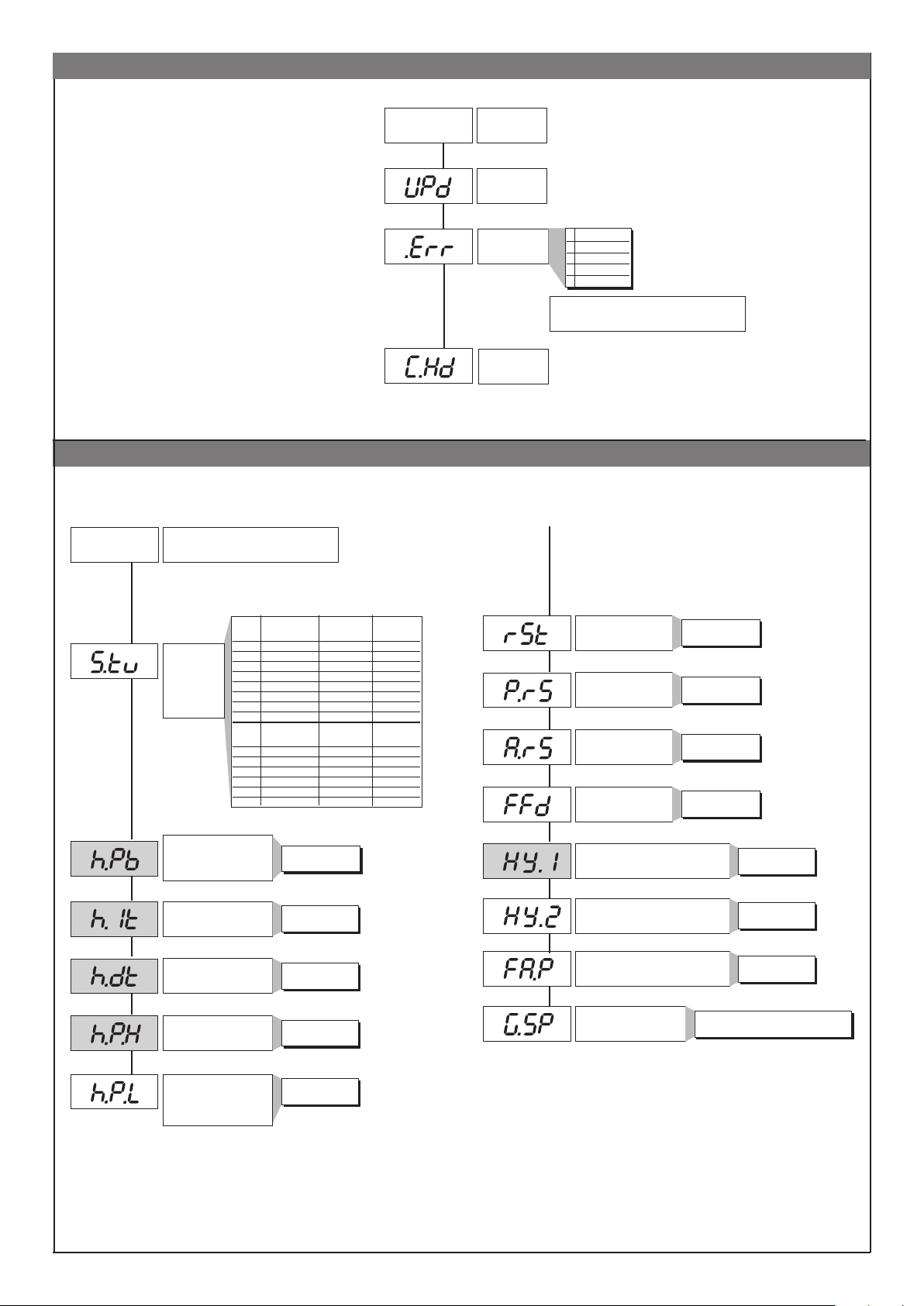
Achage InFo
CFG
Paramètres de réglage
Default: 3.10
Default: 4
Default: 213
INF
CFG
Achage
informations
Version logiciel
Code erreur
autodiagnostic
Configuration
hardware
0 No Error
1 Lo
2 Hi
3 ERR
4 SBR
+8 erreur reconnaissance carte OUT2
+16 erreur reconnaissance carte OUT3
Default: 0
Default: 30
Default: 0.2
Default: 0.01
Default: 100
Default: 0
S.tun
continu
0 NEIN NEIN NEIN
1 YA NEIN NEIN
Validation
autoadaptativité,
autoréglage,
softstart
Bande proportionnelle
de chauage ou hystérésis dans
„MARCHE/ARRÊT“ réglementaire
Temps d’intégrale de chauage
Temps de dérivée de chauage
Limite maxi puissance de
Limite mini puissance de
(non disponible pour double action
2 NEIN YES NEIN
3 YES YES NEIN
4 NEIN NEIN YA
5 YA NEIN YA
6 - - 7 - - -
S.tun
one shot
8 WAIT NEIN NEIN
9 GO NEIN NEIN
10 WAIT YA NEIN
11 GO YA NEIN
12 WAIT NEIN YA
13 GO NEIN YA
chauage
chauage
chaud/froid)
Autoréglage
Sel-ftuning Softstart
Autoréglage
Selftuning Softstart
0 ... 999.9%
pleine échelle
0.00 ... 99.99 min
0.00 ... 99.99 min
0.0 ... 100.0%
0.0 ... 100.0%
Default: 0
Default: 0
Default: 0
Default: 0
Default: -1
Default: -1
Default: 0
Default: 0
Reset manuel
Puissance de reset -100.0 ... 100.0%
Antireset
Feedforward (régulation
avec action anticipatrice)
Hystérésis pour alarme 1
Hystérésis pour alarme 2
Puissance de sécurité
(fournie dans des conditions de capteur défectueux)
Gradient de consigne
(cf. remarques d’application)
-999 ... 999
points d’échelle
0 ... 9999
points d’échelle
-100.0 ... 100.0%
±999
points d’échelle
±999
points d’échelle
-100.0 ... 100.0%
ON / OFF
0.0...999.9 digits/min.
(digits/s voir SP.r)
2828
Page 29
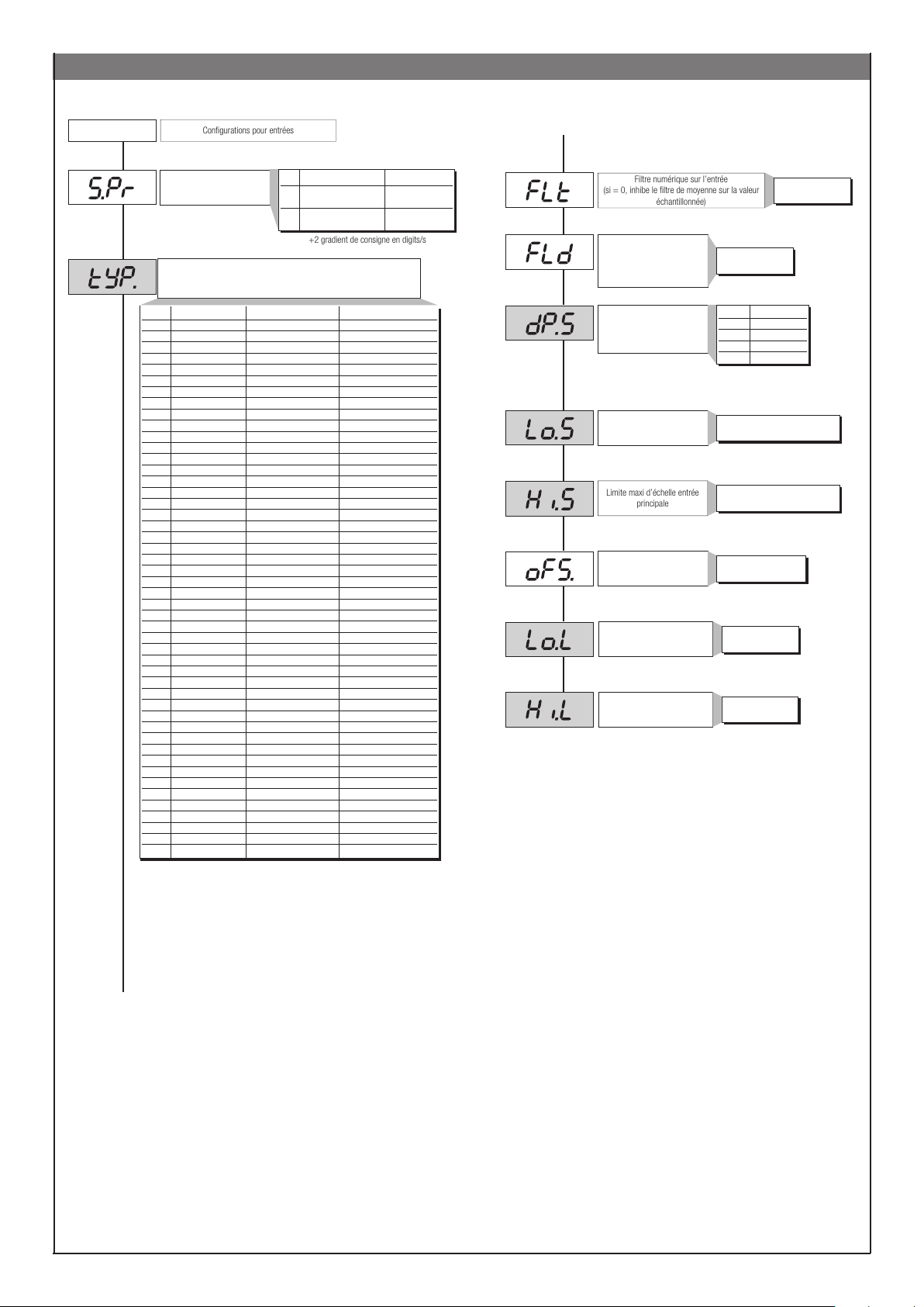
InP
Configurations pour entrées
+2 gradient de consigne en digits/s
Filtre numérique sur l’entrée
(si = 0, inhibe le filtre de moyenne sur la valeur
échantillonnée)
Limite maxi d’échelle entrée
principale
InP
Default: 0
Default: 2
Déf. Consigne externe:
Type de capteur, signal, validation linéarisation personnalisée et échelle entrée
ype Type sonde Sans point décimal Avec point décimal
Sensore: TC
0 TC J °C 0/1000 0.0/999.9
1 TC J °F 32/1832 32.0/999.9
2 TC K °C 0/1300 0.0/999.9
3 TC K °F 32/2372 32.0/999.9
4 TC R °C 0/1750 0.0/999.9
5 TC R °F 32/3182 32.0/999.9
6 TC S °C 0/1750 0.0/999.9
7 TC S ° F 32/3182 32.0/999.9
8 TC T °C -200/400 -199.9/400.0
9 TC T °F -328/752 -199.9/752.0
28 TC CUSTOM CUSTOM
29 TC CUSTOM CUSTOM
30 PT100 °C -200/850 -199.9/850.0
31 PT100 °F -328/156 2 -199.9/999.9
32 JPT100 °C -200/600 -199.9/600.0
33 JPT100 °F -328/1112 -199.9/999.9
34 PTC °C -55/120 -55.0/120.0
35 PTC °F -67/248 -67.0/248.0
36 NTC °C -10/70 -10.0/70.0
37 NTC °F 14/158 14.0/158.0
38 0...60 mV -1999/9999 -199.9/999.9
39 0...60 mV
40 12...60 mV -1999/9999 -199.9/999.9
41 12...60 mV
42 0...20 mA -1999/9999 -199.9/999.9
43 0...20 mA
44 4...20 mA -1999/9999 -199.9/999.9
45 4...20 mA
46 0...10 V -1999/9999 -199.9/999.9
47 0...10 V
48 2...10 V -1999/9999 -199.9/999.9
49 2...10 V
50 0...5 V -1999/9999 -199.9/999.9
51 0...5 V
52 1...5 V -1999/9999 -199.9/999.9
53 1...5 V
54 0...1 V -1999/9999 -199.9/999.9
55 0...1 V
56 200mv..1V -1999/9999 -199.9/999.9
57 200mv..1V
58 Cust10 V-20mA -1999/9999 -199.9/999.9
59 Cust10 V-20mA
60 Cust 60mV -1999/9999 -199.9/999.9
61 Cust 60mV
62 PT100-JPT CUSTOM CUSTOM
63 PTC CUSTOM CUSTOM
64 NTC CUSTOM CUSTOM
Val. Type consigne externe Absolue/Asservie
0 numérique absolue
(par ligne série)
1 numérique asservie à la
(par ligne série) consigne locale
principale
linéarisation personnalisée linéarisation personnalisée
linéarisation personnalisée linéarisation personnalisée
linéarisation personnalisée linéarisation personnalisée
linéarisation personnalisée linéarisation personnalisée
linéarisation personnalisée linéarisation personnalisée
linéarisation personnalisée linéarisation personnalisée
linéarisation personnalisée linéarisation personnalisée
linéarisation personnalisée linéarisation personnalisée
linéarisation personnalisée linéarisation personnalisée
linéarisation personnalisée linéarisation personnalisée
linéarisation personnalisée linéarisation personnalisée
linéarisation personnalisée linéarisation personnalisée
Default: 0.1
Default: 0.5
Default: 0
Default: 0
Default: 1300
Default: 0
Default: 0
Default: 650
Filtre numérique sur l’achage
de l’entrée
Position point décimal pour
l’échelle entrée
Limite mini d’échelle entrée
principale
Oset de correction entrée
principale
Limite basse réglage SP et
alarmes absolues
Limite haute réglage SP et
alarmes absolues
0.0 ... 20.0 s
0 ... 9.9
points d’échelle
dP_S Format
0 xxxx
1 xxx.x
2 xx.xx (*)
3 x.xxx (*)
(*) non disponible pour échelle TC,
RTD et PTC.
mini...maxi échelle de l’entrée
sélectionnée dans tyP
mini...maxi échelle de l’entrée
sélectionnée dans tyP
-999 ... 999
points d’échelle
Lo.S ... Hi.S
Lo.S ... Hi.S
Pour linéarisation personnalisée:
- on a l’indication LO avec variable à des valeurs inférieures à Lo.S ou à la valeur minimale de
calibration
- on a l’indication HI avec variable à des valeurs supérieures à Lo.S ou à la valeur maximale de
calibration
2929
Page 30
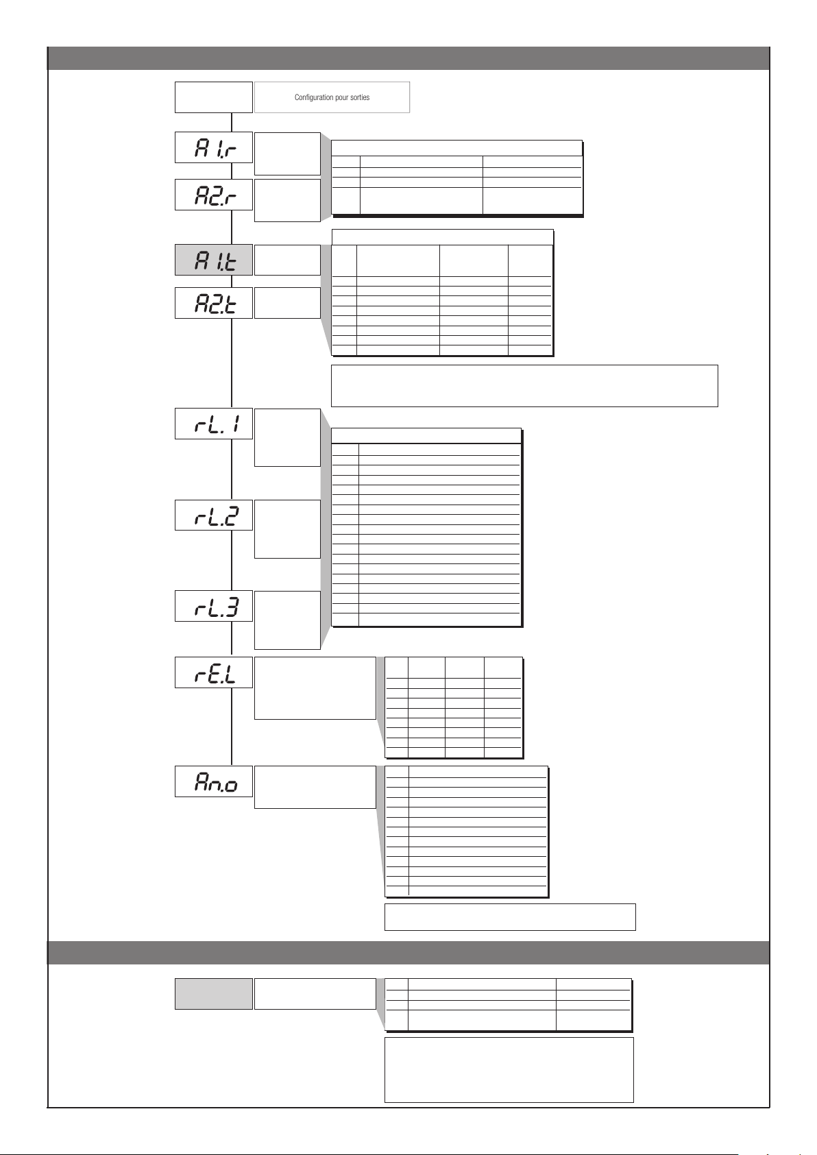
Out
Configuration pour sorties
Out
Default: 0
Default: 0
Default: 0
Default: 0
Default: 2
Default: 5
Default: 3
Default: 0
Default: 5
Sélection grandeurs
référence
alarme 1
Sélection grandeurs
référence
alarme 2
Type alarme 1
Type alarme 2
Out 1
Attribution signal de
référence
Out 2
Attribution signal de
référence
Out 3
Attribution signal de
référence
(définition état en cas de capteur
Attribution signal ou valeur de référence:
AL.x.r Variable à comparer Seuil de référence
0 PV (variable de process) AL
1 SSP (consigne active) AL (absolue uniquement)
2 PV (mesure) AL (uniquement asservie
et rapportée à SP1 avec
fonction multiset)]
AL.x.t Directe (détection haute) Absolue Normal
Inverse (détection basse) Asservie Symétrique
à la consigne active (bande)
0 directe absolute normal
1 inverse absolute normal
2 directe relativo normal
3 inverse relativo normal
4 directe absolute
5 inverse absolute
6 directe relativo
7 inverse relativo
+8 pour inhiber à la mise en marche jusqu’au premier dépassement du seuil
+16 pour valider la mémorisation de l’alarme
+ 32 Hys devient le temps de retard à l‘activation de l‘alarme (0...999 s) (absolue symétrique exclue)
+ 64 Hys devient le temps de retard à l‘activation de l‘alarme (0...999 mn) (absolue symétrique exclue)
Val Fonction
0 CHAUD (sortie régulation chauage)
1 FROID (sortie régulation refroidissement)
2 AL1 - alarme 1
3 AL2 - alarme 2
4 AL3 - alarme 3
5 AL.HB - alarme HB
6 LBA - alarme LBA
7 IN - Répétition entrée logique
8 Répétition touche but (si but = 8)
9 AL1 ou AL2
10 AL1 ou AL2 or AL3
11 AL1 et AL2
12 AL1 et AL2 et AL3
13 AL1 ou ALHB
14 AL1 ou AL2 ou ALHB
15 AL1 et ALHB
16 AL1 et AL2 et ALHB
+ 32 pour niveau logique nié en sortie sauf codes 0…1 avec sortie continue
Défaut
défectueux)
Err, Sbr
Out W
AL.1.r, AL.2.r
AL.1.t, AL.2.t
symétrique
symétrique
symétrique
symétrique
rL.o.1, rL.o.2, rL.o.3, rL.o.4
_rEL. Alarme Alarme Alarme
1 2 3
0 OFF OFF OFF
1 ON OFF OFF
2 OFF ON OFF
3 ON ON OFF
4 OFF OFF ON
5 ON OFF ON
6 OFF ON ON
7 ON ON ON
Val Grandeur de référence
0 PV - mesure
1 SSP - consigne active
2 SP - consigne locale
3 4 Écart (SSP-PV)
5 CHAUD (*)
6 FROID (*)
7 AL1 (seuil)
8 AL2 (seuil)
9 AL3 (seuil)
10 11 Valeur acquise de la liaison série (*)
16 pour la valeur 0 si l‘entrée est en condition d‘erreur Err – Sbr
la sortie prend la valeur minimale de trimming
3030
Pro
Code de protection
(PAS 99)
Prot (PAS)
Prot Achage Modification
0 SP, In2, alarmes, OuP, INF SP, alarmes
1 SP, In2, alarmes, OuP, INF SP
2 SP, In2, OuP, INF
+4 inhibition InP, Out
+8 inhibition CFG, Ser
+16 inhibition «marche - arrêt» par voie logicielle
+32 inhibe la mémorisation de la puissance manuelle
+64 inhibe la modification de la valeur de la puissance manuelle
+128 valide la configuration étendue
Page 31
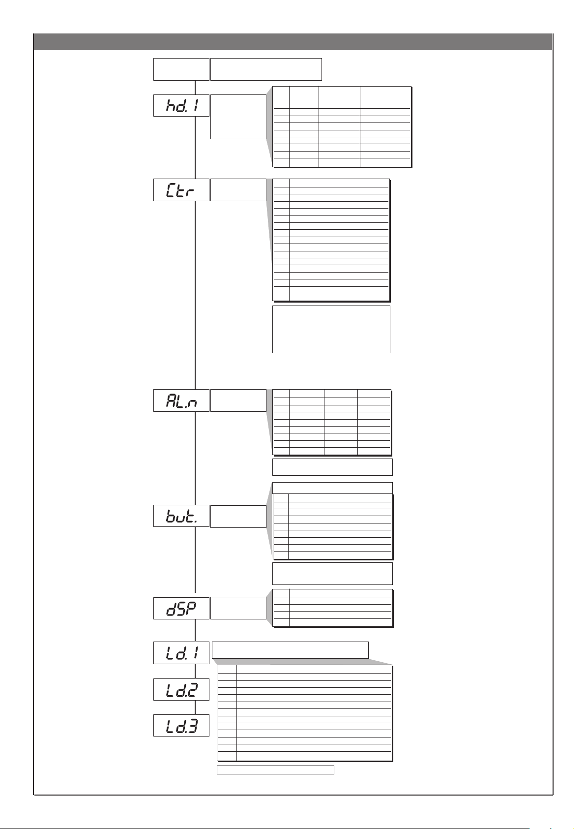
Hrd
Default: 0
Default: 70
Hrd
Configuration matériel (hardware)
Validation multiset
gestion appareils par
liaison série
Type de régulation
Val Multiset État voyants Gestion
(2 SP) inversés appareil par
liaison série
0
1 x
2 x
3 x x
4 x
5 x x
6 x x
7 x x x
Val Type de contrôle
0 P chaud
1 P froid
2 P chaud / froid
3 PI chaud
4 PI froid
5 PI chaud / froid
6 PID chaud
7 PID froid
8 PID chaud / froid
9 ON-OFF chaud
10 ON-OFF froid
11 ON-OFF chaud / froid
12 PID chaud + ON-OFF froid
13 ON-OFF chaud + PID froid
14 PID chaud + froid avec gain relatif
(cf. paramètre C.MEd)
Sélection temps d’échantillonnage de l’action dérivée:
+0 échantillonnage 1 s
+16 échantillonnage 4 s
+32 échantillonnage 8 s
+64 échantillonnage 240 ms
Default: 3
Default: 1
Default: 0
Sélection alarmes
validées
Fonction des touches
M/A
Définition fonction
acheur SV
Nota: En régulation du type ON-OFF, l’alarme LbA
est inhibée.
AL.nr Alarme 1 Alarme 2 Alarme 3
0 inhibée inhibée inhibée
1 validée inhibée inhibée
2 inhibée validée inhibée
3 validée validée inhibée
4 inhibée inhibée validée
5 validée inhibée validée
6 inhibée validée validée
7 validée validée validée
+8 pour valider l’alarme HB.
+16 pour valider l’alarme LBA.
b u t t
0 aucune fonction (touche inhibée)
1 MAN / AUTO régulateur
2 LOC / REM
3 HOLD
4 Reset mémorisation alarmes
5 Sélection SP1 / SP2
6 Start / Stop autoadaptativité
7 Start / Stop autoréglage
8
Activation / Désactivation sorties Out 1... Out 4
+ 16 exclut la fonction „back menu“ (touches Auto/Man
+ F) à l‘intérieur des menus de configuration
diSP Fonction acheur inférieur (SV)
0 SSP - consigne active
1 InP.2 - entrée auxiliaire
2 Valeur sortie de régulation
3 Écart (SSP - PV)
Default: 1
Default: 10
Default: 20
Fonction led
Val. Fonction
0 Aucune fonction
1 MAN/AUTO régulateur
2 LOC / REM
3 HOLD
4 Autoréglage actif
5 Autoadaptativité active
6 Répétition IN1
7 Validation communication série
8 Erreur présente
9 Softstart en exécution
10 Indication SP1...SP2
11 Gradient du point de consigne en cours d‘exécution
+ 16 Si le voyant est allumé, il clignote
3131
Page 32
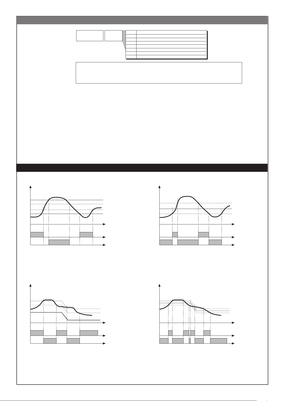
U.CAL
Val Fonction
1 Sortie analogique (1)
2 Entrée 1 – personnalisée 10V/ 20mA
3
Entrée 1 - capteur personnalisé 60 mV
4 Personnalisée PT100 / J PT100
5 Personnalisé PTC
6 Personnalisé NTC
7 Entrée 2 - personnalisé TA (2)
Default: 0
U.CA
Étalonnage
utilisateur
(1) La sortie analogique en 20 mA est calibrée avec une précision meilleure que 0,2% p.e., procéder à la calibration si
on désire la convertir en sortie 10 V.
(2) La précision en l’absence de calibration est meilleure que 1% p.e., procéder à la calibration uniquement pour des
exigences de précision supérieure
ALARMES
Alarme absolue du type normal Alarme absolue du type symétrique
AL2
AL1
alarme 1
alarme 2
Pour AL1 alarme absolue inverse (valeur mini) avec Hyst 1 positive, AL1 t = 1
(*) = OFF s’il existe une inhibition à la mise en marche.
Pour AL2 alarme absolue directe (valeur maxi) avec Hyst 2 négative, AL2 t = 0
SP+AL1
(*)
Alarme asservie à la consigne du type normal Alarme asservie à la consigne du type symétrique
SP
AL2 + Hyst2
AL1 + Hyst1
temps
Hyst1
AL1 + [ Hyst1 * ]
AL1
AL1 - [ Hyst1 * ]
temps
inverse
directe
Pour AL1 alarme absolue inverse symétrique avec hystérésis Hyst 1, AL1 t = 5
Pour AL1 alarme absolue directe symétrique avec hystérésis Hyst 1, AL1 t = 4
* Hystérésis minimum = 2 points d’echelle
SP+AL1
SP
SP-AL1
inverse
directe
Pour AL1 alarme asservie inverse normale avec hystérésis Hyst 1 négative, AL1 t = 3
Pour AL1 alarme asservie directe normale avec hystérésis Hyst 1 négative, AL1 t = 2
3232
temps
temps
inverse
directe
Pour AL1 alarme asservie inverse symétrique avec hystérésis Hyst 1, AL1 t = 7
Pour AL1 alarme asservie directe symétrique avec hystérésis Hyst 1, AL1 t = 6
Page 33
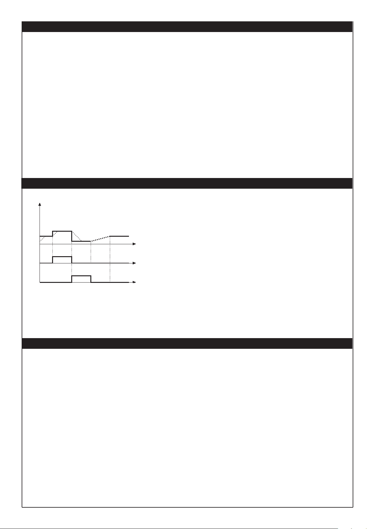
ACTIONS DE REGULATION
Action proportionnelle:
action dans laquelle la contribution sur la sortie est proportionnelle à l’écart en entrée (à savoir l’écart entre la mesure et la consigne).
Action dérivée:
action dans laquelle la contribution sur la sortie est proportionnelle à la vitesse de variation de l’écart en entrée.
Action intégrale:
action dans laquelle la contribution sur la sortie est proportionnelle à l’intégrale dans le temps de l’écart en entrée.
Influence des actions Proportionnelle, Dérivée et Intégrale sur la réponse du process à réguler
* L’augmentation de la Bande Proportionnelle réduit les oscillations mais augmente l’écart.
* La diminution de la Bande Proportionnelle réduit l’écart mais provoque des oscillations de la mesure (des valeurs trop basses de la Bande Proportionnelle
rendent le système instable).
* L’augmentation de l’Action Dérivée, correspondant à une augmentation du Temps de Dérivée, réduit l’écart et permet d’éviter les oscillations jusqu’à une
valeur critique du Temps de Dérivée au-delà de laquelle l’écart augmente et des oscillations prolongées se produisent.
* L’augmentation de l’Action Intégrale, correspondant à une diminution du Temps d’Intégrale, tend à annuler l’écart en régime entre la mesure et la consigne.
Si la valeur du Temps d’Intégrale est trop grande (Action Intégrale faible), on peut avoir une persistance de l’écart entre mesure et consigne.
Pour d’autres informations relatives aux actions de régulation, contacter GEFRAN.
FONCTION MULTISET, GRADIENT DE CONSIGNE
On valide la fonction multiset en hd.1.
La fonction gradient est toujours validée.
La sélection entre consigne 1 et consigne 2 peut être eectuée par touche frontale ou entrée
logique.
On peut visualiser la sélection entre consignes 1 / 2 par LED.
GRADIENT DE CONSIGNE: s‘il est configuré π 0, à la mise en marche et au passage auto/man,
la consigne prend la valeur PV, avec gradient configuré elle atteint la consigne locale ou celle
t
sélectionnée.
Toute variation de consigne est sujette à un gradient.
Le gradient de consigne est inhibé à la mise en marche quand l‘autoadaptativité est validée.
t
Si le gradient de consigne est configuré π 0, il est actif même sur les variations de consigne
locale, programmable uniquement dans le menu SP correspondant.
La consigne de régulation atteint la valeur configurée avec une vitesse définie par le gradient.
t
LOC/REM
SP
IN1
SP1
SP2
ON
SPrem
ON
SP1
(*)
(*) lorsque le gradient de consigne
est configuré
MARCHE / ARRÊT PAR VOIE LOGICIELLE
Arrêt: par la combinaison des touches «F» et «Incrémentation» appuyées en même temps pendant 5 secondes, on peut, sans couper l’alimentation secteur, désactiver l’appareil
qui se met dans l’état «OFF» et se comporte comme un appareil éteint, l’achage de la mesure restant toutefois actif. L’acheur SV est éteint.
Toutes les sorties (régulation et alarmes) sont à l’état OFF (niveau logique 0, relais au repos) et toutes les fonctions de l’appareil sont inhibées, à l’exception de la fonction de
«MISE EN MARCHE» et de la communication série.
Mise en marche: en appuyant sur la touche «F» pendant 5 secondes, l’ appareil passe de l’état «OFF» à l’état «ON». Si, pendant l’état «OFF», la tension secteur est coupée, à la
remise en marche suivante (mise sous tension), l’ appareil se met dans le même état «OFF»; (l’état de «ON/OFF» est mémorisé). Cette fonction est normalement activée; pour la
désactiver, programmer le paramètre Prot = Prot +16. Cette fonction peut être associée à une entrée logique (d.i.G.) et interdit la désactivation par le clavier.
3333
Page 34

34
Page 35

35
Page 36

®
Your authorised Service Centre is:
© Copyright by Leister
Leister Technologies AG
Galileo-Strasse 10
CH-6056 Kaegiswil/Switzerland
Tel. +41-41662 74 74
Fax +41-41662 74 16
www.leister.com
[email protected]
CSS EASY / CSS / KSR DIGITAL / 06.2007 / 01.2018
 Loading...