

Page 1
Page 2
CONTE NTS and STANDAR DS
ii
SUPERJIG-12-18-24 User Guide
Your New Leigh Dovetail Jig
Congratulations! You now own a most useful and versatile
dovetailing tool. The Leigh Superjig Dovetail Jig will help you
cut an infinite variety of joints, and all of its major functions
are described in detail in this manual, plus there's a slide-out
Quick Reference Guide underneath the jig. A very helpful
DVD is also included, but the manual is essential reading.
We recommend that you first assemble and mount the jig,
carefully following the instructions in the first section of the
manual. Then read the rest of the manual, following along
with the basic functions and principles of operation, before
you try to do any actual joinery routing. By all means, cut a
few practice joints in scrap boards before you use the jig to
rout a precious hardwood work piece!
If you have any questions that are not answered in the manual,
please call the Leigh customer support line*.
But remember: “If at first you don’t succeed, read the instructions!”
*See Appendix IV – Customer Support
Important! Inches and Millimetres
The Superjig can be ordered in inch or metric versions. They're
identical except for the calibration scales. This Leigh Englishlanguage user guide show measurements in both inches and
millimetres, with “inches” first, followed by “millimetres” in
square brackets.
Example:
3
⁄4"x 51⁄2"x8" [20x140 x 200mm]
Do not be concerned if the inch/millimetre equivalents are not
exact. Just use the dimensions which apply to your jig.
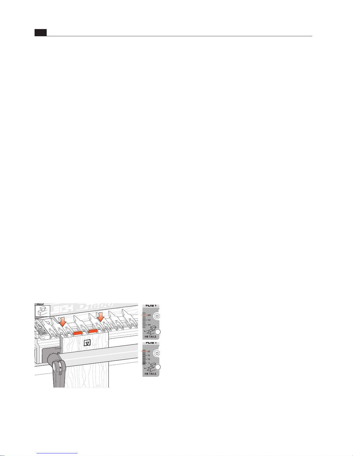
Where finger assembly scales overlay an illustration, the “inches”
scale
will be at the top, the “millimetres” scale will be at the
bottom. Only the front “active” half of the scales are illustrated.
For clarity, setting positions are indicated with a red line in the
manual only. On the jig, the lines are black.
1
2
© 2007 Leigh Industries Ltd. All rights reserved.
Page 3

iii
CONTE NTS and STANDAR DS
SUPERJIG-12-18-24 User Guide
CONTENTS and Standards ........................................................................................iii
Chapter 1 – Jig Assembly, Mounting, and Using The Clamps ..................................1
Chapter 2 – Adjusting the Finger Assembly ............................................................. 7
Chapter 3 – Guidebushes and the unique Leigh e-Bush .......................................... 9
Chapter 4 – Basic Jig Functions and Scale Modes ................................................... 11
Chapter 5 – Using Your Jig Safely ............................................................................13
Chapter 6 – Wood Preparation ................................................................................ 15
Chapter 7 – Router Preparation ............................................................................... 17
Chapter 8 – Through Dovetail Procedures .............................................................. 19
Chapter 9 – Variably Spaced Half-Blind Dovetail Procedures ................................ 29
Chapter 10 – One-Pass Half-Blind Dovetails ........................................................... 37
Chapter 11 – Rabbeted Half-Blind Dovetails .......................................................... 43
Chapter 12 – Asymmetric Dovetails ....................................................................... 45
Chapter 13 – Sliding Dovetails .................................................................................49
Chapter 14 – Box Joints ............................................................................................ 55
Chapter 15 – Hints and Tips ..................................................................................... 61
Appendix I – Attaching the Leigh e-Bush to the Router ........................................65
Appendix II – Bit Selection ....................................................................................... 67
Appendix III – Jig Parts List ...................................................................................... 73
Appendix IV – Customer Support ............................................................................ 78
© 2007 Leigh Industries Ltd. All rights reserved.
Page 4
CONTE NTS and STANDAR DS
iv
SUPERJIG-12-18-24 User Guide
1
2
1
Glossary of Symbols
To help you understand the instructions and illustrations in this
manual, we have used a number of international symbols, plus
a few special ones of our own. They are all explained below. You
needn’t worry about memorizing these symbols now, because
they are repeated quite frequently in the manual, and you will
soon get used to them.
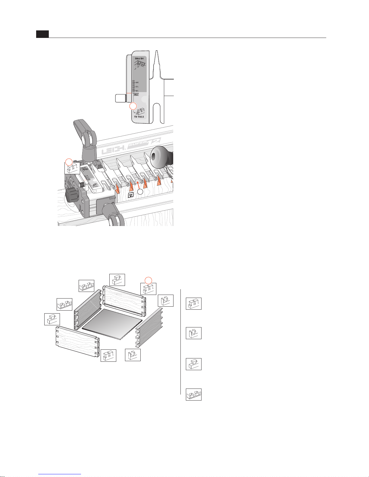
The Leigh jig’s guidefinger assembly can be in any one of four
joint modes, depending on what type of joint and which part of
the joint you are cutting. Each finger assembly scale has it’s own
mode icon
, identifying that joint part. You will also find the
joint mode icon in the top left corner of most illustrations
,
indicating which finger assembly mode to use.
Sometimes a joint mode icon will be used to identify a
board
.
These are the four joint mode icons:
TD Tails
(tails for through dovetail joints)
TD Pins
(pins for through dovetail joints)
HB Tails
(tails for half-blind dovetail joints)
HB Pins
(pins for half-blind dovetail joints)
3
© 2007 Leigh Industries Ltd. All rights reserved.
Page 5
v
CONTE NTS and STANDAR DS
SUPERJIG-12-18-24 User Guide
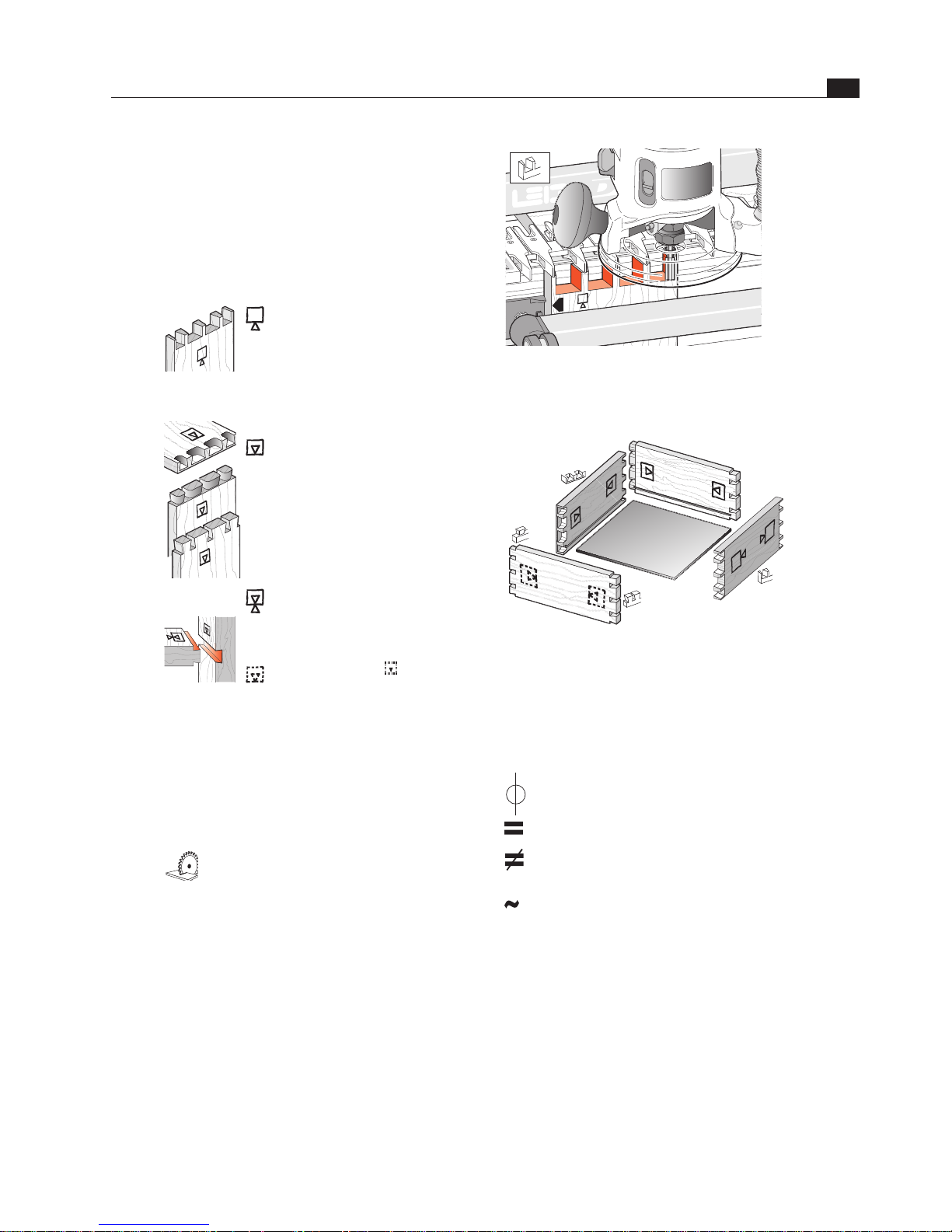
Which Way Round Should the Board Go?
As virtually all dovetail joinery is used to make boxes,
drawers and chests etc., we devised these simple (and
hopefully intuitive) icons to indicate which side of a
board faces inwards or outwards on the finished “box”,
and which side of the board faces outward (toward
you, the operator), when it is clamped in the jig.
The following symbols indicate:
This edge against sidestop
This edge against sidestop
Sawcut allowance
Caution: use special care for this
operation
Numbered References in text
This icon indicates the “outside”
of a board. All through dovetail
pin boards are mounted in the
jig with this “outside” face away
from the jig (toward you, the
operator).
This icon
indicates the “inside”
of a board. All half-blind pin and
half-blind tail boards, and through
dovetail tail boards, are mounted
in the jig with the “inside” face
away from the jig toward you,
the operator.
This icon indicates boards that
are mounted both ways e.g. sliding
dovetails and box joints.
Dotted line icons
indicate the
“other” side of the board in the
illustrations.
Centreline of board or layout
Equals
Does not equal
Approximately
© 2007 Leigh Industries Ltd. All rights reserved.
Page 6

CONTE NTS and STANDAR DS
vi
SUPERJIG-12-18-24 User Guide
© 2007 Leigh Industries Ltd. All rights reserved.
Page 7
10
1 2 3 4
5 6 7 8
9
Jig Assembly, Mounting,
and Using the Clamps
SUPERJIG - CHAPTER 1
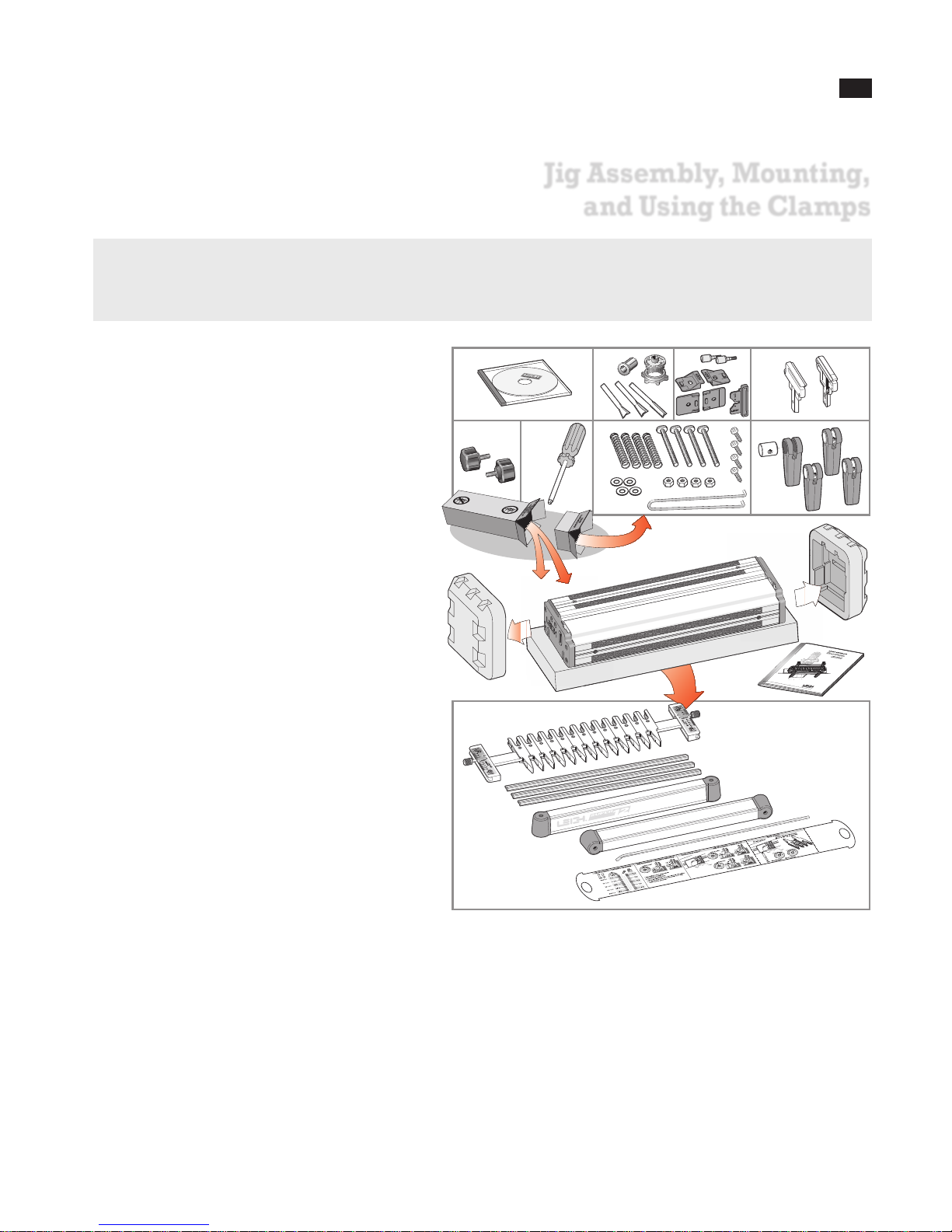
Make Sure You Have All the Parts.
Before you start to assemble your Leigh SUPERJIG, check to make sure you have received all the required parts.
The small carton you removed from the end of the main
carton contains:
1. DVD instructional video (English only)
2. 2 Dovetail bits, 1 straight bit, 1 Collet Reducer, 1
e7-Bush & Nut
3. 2 scale thumbscrews c/w nylon washers
2 each, front and rear Side Stops
1 Spacer
4. 2 support brackets
5. 2 support knobs
6. Square-head guidefinger screwdriver
7. 4 clamp springs
4 clamp T-bolts
4 flat washers
4 T-bolt nuts
4 Jig Hold-down Wood Screws No.10 x1"
1 Pin Wrench
8. 4 cam-action speed clamps
4 cam clamp pivot nuts
…and any other small optional items you may have
ordered with your new jig. Check the packing slip
for this information.
The main carton contains:
9. 1 main jig body
1 Leigh jig User Guide
The large inner box contains:
10. 1 finger assembly on a bar, complete with scales
Super12, with 13 guidefingers
Super18, with 16 guidefingers
Super24, with 19 guidefingers
2 lengths bridge material
1 cross cut fence (identical to bridge)
2 clamp bars c/w end plugs
1 Nylon Stop Rod
1 Quick Reference pull-out card
If any items are missing from your jig, contact your supplier
or Leigh Industries immediately.
Important Note
Mount your jig securely and assemble it completely before you try to use it.
Make sure you have read and understood all
the material in the Safety section of this user
guide before using the jig.
1
© 2007 Leigh Industries Ltd. All rights reserved.
Page 8
JIG ASSEMBLY, MOUNT ING, AND USING THE CLAMPS
2
Chapter 1 SUP ER JI G-12-18-24 User Guide
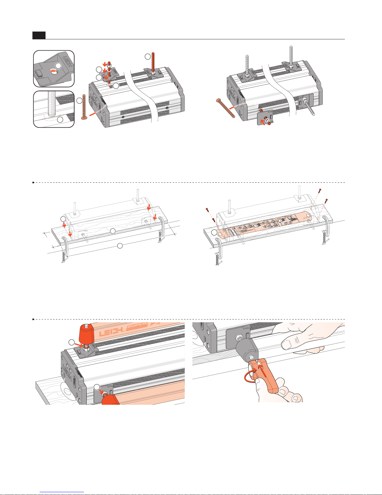
1-1 Install Side Stops Insert two clamp T-bolts through
the rear jig body holes
and place a “stepped” rear side stop over
each bolt
, using the rear part of the double-hole . Make
sure the bolt's “T” is between the extrusion ribs
. Don’t forget
the steel washer
and use a ½"[13mm] wrench to tighten the
nuts.
3
1
4
4
1
2
5
1-2 Insert the two front clamp T-bolts through the jig body
holes. Make sure the bolt's “T” is between the extrusion ribs.
Place a front side stop and steel washer over each bolt but only
finger-tighten the front nuts; you will need to index these to the
rear stops later.
1-3 Prepare a flat ¾"[20mm] mounting board (plywood or MDF),
at least 5"[125mm] wide. Length
: 26" for Super12, 32" for Super18,
40" for Super24 [660, 830 or 1000mm respectively]. Clamp it to the
front of your bench. Centre the jig on the board, front face slightly
overhanging the board edge
. Mark the four hold down screw posi-
tions. Drill small pilot holes at a slight angle
.
2
3
5"
[125mm]+
1
1-4 Quick Reference Pull-Out Decide whi ch en d
of the jig you wish to access the “Quick Reference” instruction
pull-out and place the jig over the pull-out
. Using the screws
provided; screw the jig to the board. Make sure that the pull-out
slides freely.
1
1-5 Place four springs and two clamp bars on the T-bolts.
Make sure the clamp bars move freely on the T-bolts.
1
1
1-6 Screw a clamp lever assembly onto each T-bolt.
© 2007 Leigh Industries Ltd. All rights reserved.
Page 9
3
JIG ASSEMBLY, MOUNT ING, & USING THE CLAMPS
Chapter 1SUP ER JI G-12-18-24 User Guide
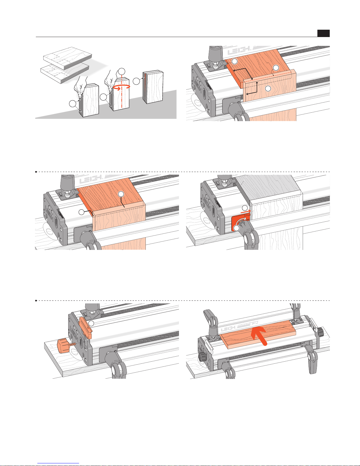
1-7 Now you need t wo boards about ¾" x 6" x 8" long
[20 x 150 x 200mm]. Both must have perfectly square ends to accu-
rately index the front and rear side stops.
D
Check for squareness: stand both pieces vertically on a flat
surface. Make sure side edges are flush at bottom and top
.
Turn one piece around on its end
. If side edges are flush top to bot-
tom
, the boards are square. If not, ; cut two that are.
90˚
90˚
90˚
90˚
1
4
2
3
1-8 Align Front Side Stops Clamp one square ended board
in the front, not touching the left side stop and with the top edge above
the top surface of the jig body
. Place the other square board in the rear
clamp, tight against the left rear side stop
, with its front edge touching
flush across the rear of the vertical board
. Tighten the rear clamp.
3
90˚
90˚
1
2
1-9 Now loosen the front clamp and position the front board so
its top end edge is perfectly flush and level with the top face of the
horizontal board
and, both boards left edges are also perfectly
flush
. Tighten the clamp.
1
2
1-10 Now push the front left side stop inwards and flush against
the vertical board
and firmly tighten the clamp bolt nut.
Repeat operations 1-8 thru 1-10 at the right side of the jig. The
front and rear side stops are now indexed to provide accurate
board alignment in all routing procedures. You may now remove
the boards.
1
2
1-11 Insert the right and left support brackets. Attach the knobs,
raise them to full height and tighten the knobs.
Note: For clarity, the set lines on support brackets are shown in
red in this user guide. The actual bracket lines are black.
1
1-12 Make up a 3⁄4"x 6"[20 x 150mm] finger support board as
shown. Lengths: 11"[280mm] for Super12, 17"[430mm] for
Super18, and 23"[600mm] for Super24. This board will support
the guidefinger assembly in all front-clamping vertical board
modes. Clamp it in the rear of the jig.
© 2007 Leigh Industries Ltd. All rights reserved.
Page 10
JIG ASSEMBLY, MOUNT ING, AND USING THE CLAMPS
4
Chapter 1 SUP ER JI G-12-18-24 User Guide
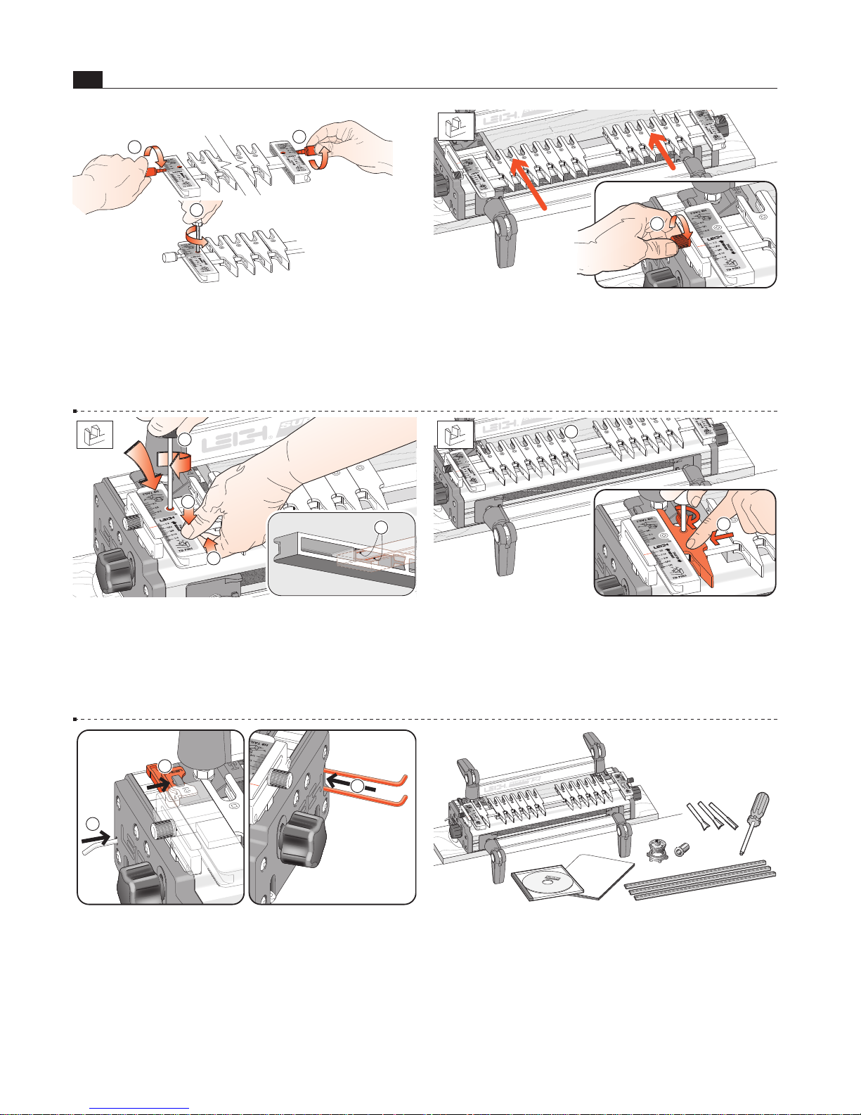
1-13 Before using the jig, the scales must be set into position on
the finger assembly. Install the two thumbscrews a few turns into
the scales
. Loosen the scale lock screw at each end by one
turn only.
1
2
1
1
1-15 Pull up on the finger bar while pushing down on the
scale
to ensure the bar is touching the two registration pads
inside the scale. Maintain pressure and tighten the scale lock-
screw
. Repeat at the other end. To maintain correct finger
assembly alignment, follow this procedure whenever you remove
the scales from the finger assembly.
3
4
2
1
1-16 With the finger assembly in +TD Pins mode , move the
outer end guidefingers to touch the scale block and lock in position
. Note: the outer end guidefingers are used for router support
only. When guidefingers are loosened, the finger assembly should
easily slide on the support brackets. If not, apply a little candle
wax to the mating surfaces.
1
2
1-17 Finally, slip the Spacer on the outside of the left rear side
stop
, the nylon stop rod through its storage hole in the left end
and the pin wrench in its slot in the right hand end housing
.
1
2
3
1-18 With Superjig assembled and mounted, you have some
items left over:
1-14 Slide the finger assembly onto the support brackets, in
the +TD Pin mode and set on the
1
⁄2"[12,7mm] setting. First,
tighten both thumbscrews
.
Do not lower the assembly onto the finger support board.
1 Leigh jig user guide
1 DVD instruction video (English only)
1 Leigh e7-Bush and nut
2 Dovetail bits
1 Straight bit
1 Collet Reducer
1 square-head screwdriver
3 bridge-piece/crosscut extrusions
© 2007 Leigh Industries Ltd. All rights reserved.
Page 11
5
JIG ASSEMBLY, MOUNT ING, & USING THE CLAMPS
Chapter 1SUP ER JI G-12-18-24 User Guide
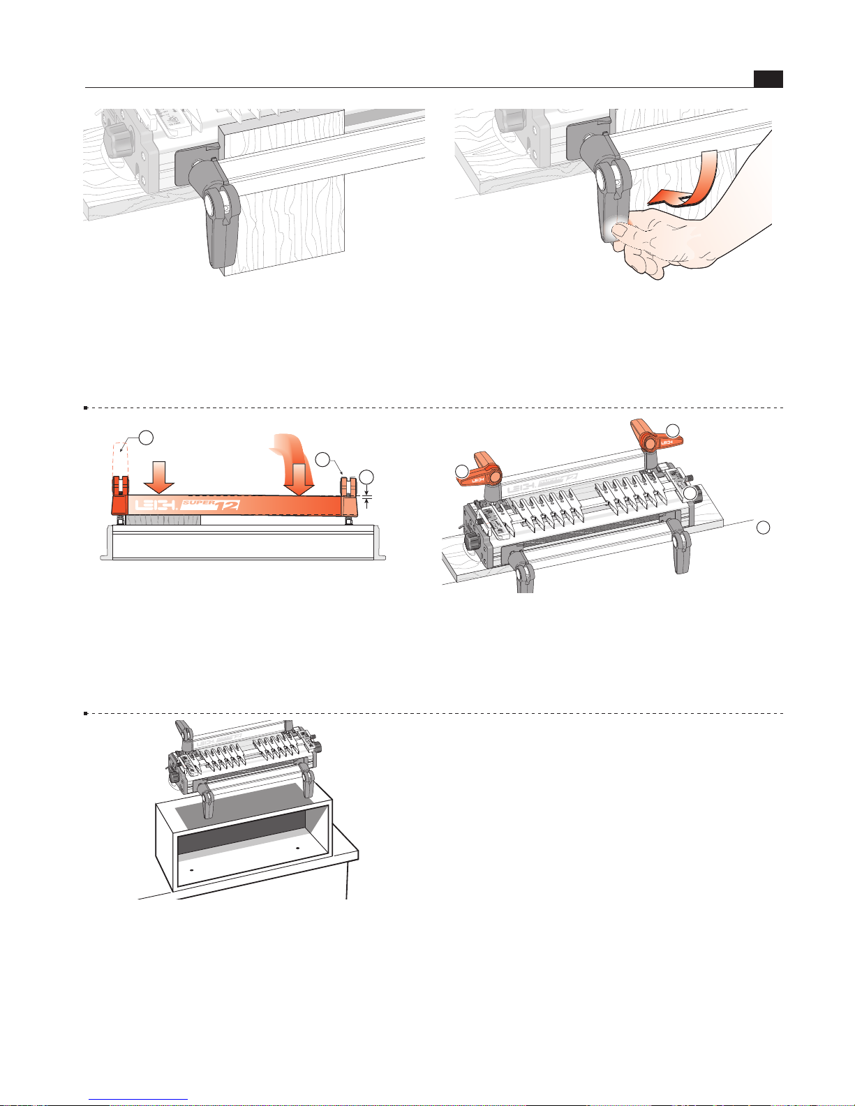
1-19 The Jig Clamps Use a piece of flat, even-thickness wood
to familiarize yourself with the jig cam clamps.
You will operate
the cam-action speed clamps every time you use the jig, so get
used to the feel of the clamps first. Do not force the cam-action
speed-clamp. It has great leverage, and excessive force may damage
the workpiece or the jig.
1-20 A smooth, firm action is enough to engage the clamp.
Rule of thumb: If you can't throw the lever by pressing the end
of it firmly with your thumb, reduce the tension. Firm thumb
pressure is about right. A few minutes of trial and error will help
you feel the right clamp tension.
1-21 For all but the wider workpieces, you need only operate the
clamp on the workpiece end of the jig to release the board
. For
narrower boards, the clamp at the free end
should be just tight
enough to bow the clamp bar about
1
⁄16"[2mm] .
1
2
3
1-22 When engaged, the front clamp levers should normally point
down and the rear levers should point away from the operator
or up to 90˚ either side as required to obtain the optimum
clamping pressure.
1
2
2
1
1-23 To gain height for a more comfortable working position
or for routing longer boards, mount the jig to a box that can be
bolted securely to a bench.
See also 15-13.
N
© 2007 Leigh Industries Ltd. All rights reserved.
Page 12

JIG ASSEMBLY, MOUNT ING, AND USING THE CLAMPS
6
Chapter 1 SUP ER JI G-12-18-24 User Guide
© 2007 Leigh Industries Ltd. All rights reserved.
Page 13

Template Guidebush System Selection Chart
I
MPORTANT: Check the make and model of your router in column 1. Where possible, always order the Leigh adaptors and template guide bushes (indicated in red), which are specially designed for use on
Leigh jigs. (711TP) Order no. 477009 (e7) Order no. 478260 (716TP) Order no. 477011. The e7 is standard with new Leigh jigs.
N
ote: Adaptor mounting screws are provided with most routers. 5/8" O.D. guide bushes are used only with 1/2" shank router bits. * Leigh Adaptors 702, 702R, and 703 may require a small lug to be
“drilled out” to use the e7 guide bush. Note: Ideal barrel depth is 1/4" to 9/32" (6mm to 8mm) below the router base. Other manufacturers’ guide bushes may require careful cutting to length. All Leigh
g
uide bushes have 9/32" long barrels.
R
OUTER MAKER ROUTER MODEL LEIGH OR ROUTER
M
AKER’S
ADAPTOR NO.
O
RDER NO.
7/16”OUTSIDE
D
IAMETER GUIDE
B
USH NO.
5/8”OUTSIDE
D
IAMETER GUIDE
B
USH NO.
WORKS WITH
L
EIGH VGS
AW635R 710 210500 711TP or e7 716TP YES
AW127R 710 210500 711TP or e7 716TP YES
All Professional, HD 1250, BP400K, 7614 No adaptor required 711TP or e7 716TP YES
SR100, 7AEE, KW780 series, KW800, KW850 710 210500 711TP or e7 716TP YES
POF800ACE. POF1400ACE, POF1100ACE, POF1200ACE, RA1100 required
GOF900ACE, GOF1300ACE, GOF900CE, GOF2000CE, GOF1200 for 711TP, 716TP
GMF1400 and VGS 800439 711TP or e7 716TP YES
1611, 1611EVS, 1615, 1615EVS, B1550, GOF1600, GOF1700ACE 702* 410003 711TP or e7 716TP YES
1E
702R* 410001 711TP or e7 716TP YES
DW613, DW615(UK) 710 210500 711TP or e7 716TP YES
DW621K & DW626 (UK) 706R 410005 or 706 711TP or e7 716TP YES
DW625 Type 1, 2, 3, 5 (UK) 702* 410003 711TP or e7 716TP YES
DW624 & DW625 Type 4 (UK), DW625EK 702R* 410001 711TP or e7 716TP YES
OF15, OF15E, OF97, OF97E 706R 410005 or 706 711TP or e7 716TP YES
MOF68, MOF69, MOF96, MOF96E 710 210500 711TP or e7 716TP YES
MOF131, MOF177 Type 1, 2 & 3 702* 410003 711TP or e7 716TP YES
MOF177 Type 4, MOF177EK 702R* 410005 or 706 711TP or e7 716TP YES
3337, 3338, 3339 702* 410003 711TP or e7 716TP YES
OF1E, OF2E, OF650, OF900E, OF1000, OF1010E 704R 310023 711TP or e7 716TP YES
OF2000, OF2000E 705R 310024 711TP or e7 716TP YES
OF1400 UK 493566 - 711TP or e7 716TP YES
OF2200 494627 O-Ring
requred to keep
guidebush centred - 711TP or e7 716TP YES
FT1700(2), FT2000, FT2200, FT3000
721 210899 711TP or e7 716TP YES
TR8, TR12, FM8, M8, M12 Series 325211 or 703* 410006 711TP or e7 716TP YES
M12VC, KM12SC, KM12VC No adaptor required - 711TP or e7 716TP YES
M12SA2, M12V2 325224 - 711TP or e7 716TP YES
L065E
702* 410003 711TP or e7 716TP YES
RP1801, RP2301FC 721 210899 711TP or e7 716TP YES
3600, 3606, 3608, 3612, 3612B, 3612BR, 3612C N. America
3620, 3621, RP0900K 703* 410006 711TP or e7 716TP YES
3612C Europe Qk. Fit Base 721 210899 711TP or e7 716TP YES
3601B 321 493-1 - 711TP or e7 716TP YES
RP0910, RP1110C 706R 410005 or 706 711TP or e7 716TP YES
RF1100, RF1101, RD1100, RD1101, RP1101 No adaptor required - 711TP or e7 716TP YES
OF1612, OFE1812
704R 310023 711TP or e7 716TP YES
OF808 Series, OFE6990
710 210500 711TP or e7 716TP YES
All
710 210500 711TP or e7 716TP YES
R2930
704R 310023 711TP or e7 716TP YES
R30, R50, R150, R151, RE155, R500, R501, R502 703* 410006 711TP or e7 716TP YES
R600, R601, RE600, RE601 702* 410003 711TP or e7 716TP YES
R160, R161, R162, R163K, R165, R170, R175, RE175, R180,
R180PL, R181, R185, ERT1150 706R 706 711TP or e7 716TP YES
1823 or 1835 91803 - 711TP or e7 716TP YES
All others No adaptor required - 11592 71021 NO
SK1810, 1815, 1820, 1825 RAS140 - 711TP or e7 716TP YES
T3, T4 710 210500 711TP or e7 716TP YES
T5, T9 710 210500 711TP or e7 716TP YES
T10, T11EK 710 210500 711TP or e7 716TP YES
TRC001, TRA001 TGA006 (or 704R) 310023 711TP or e7 716TP YES
MOF001 TRA359 - 711TP or e7 716TP YES
AXMINSTER WHITE
BLACK & DECKER
BOSCH
CMT
DEWALT
ELU
FESTOOL
FREUD
HITACHI
MAFELL
MAKITA
METABO
PERLES
POWER DEVIL
RIDGID
RYOBI
SKIL
TREND (FELLISATI)
TRITON
 Loading...