

Page 1
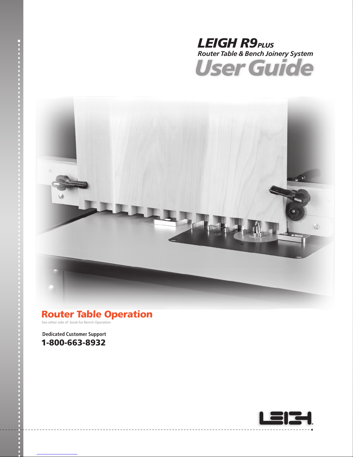
Router Table & Bench Joinery System
LEIGH R9
PLUS
User Guide
See other side of book for Bench Operation
Router Table Operation
Dedicated Customer Support
1-800-663-8932
Page 2

22
ROUTER TABLE OPERATION
Your New Leigh R9PLUS Joinery System
for Dovetails and Box Joints
R9PLUS Joinery System User Guide
Introduction
Note: There are two user guides in this book. This user guide is for
Router Table Operation. Flip the book over for Bench Operation.
The R9PLUS Joinery System was designed to overcome the
restrictions of fixed width jigs. Because of its unique “step over”
feature, it is possible to rout Through Dovetails and Box Joints
on boards of ANY width!
The R9
PLUS
can be used as a template jig with a hand-held router
or as a router table template. In either mode, you will be able
to rout multiple sizes of perfectly fitting through dovetails and
box joints.
Customer Support
If you have any questions that are not answered in this user guide,
please call Leigh Customer Support: 1-800-663-8932 in North
America or email: [email protected] For support contacts in
your country of purchase see the Customer Support section of
the Appendix.
Reminder: If at first you don’t succeed, read the instructions!
Important! Inches and Millimeters
Text and illustrations in this English language user guide
indicate dimensions in both inches and millimeters, with
“inches” first, followed by “millimeters” in square brackets, i.e.
1
⁄2"x 2"[12x50mm].
Do not be concerned that the inch/millimeter equivalents are
not mathematically “correct.” Just use the dimensions that
apply to your guides and bits.
Patents Pending
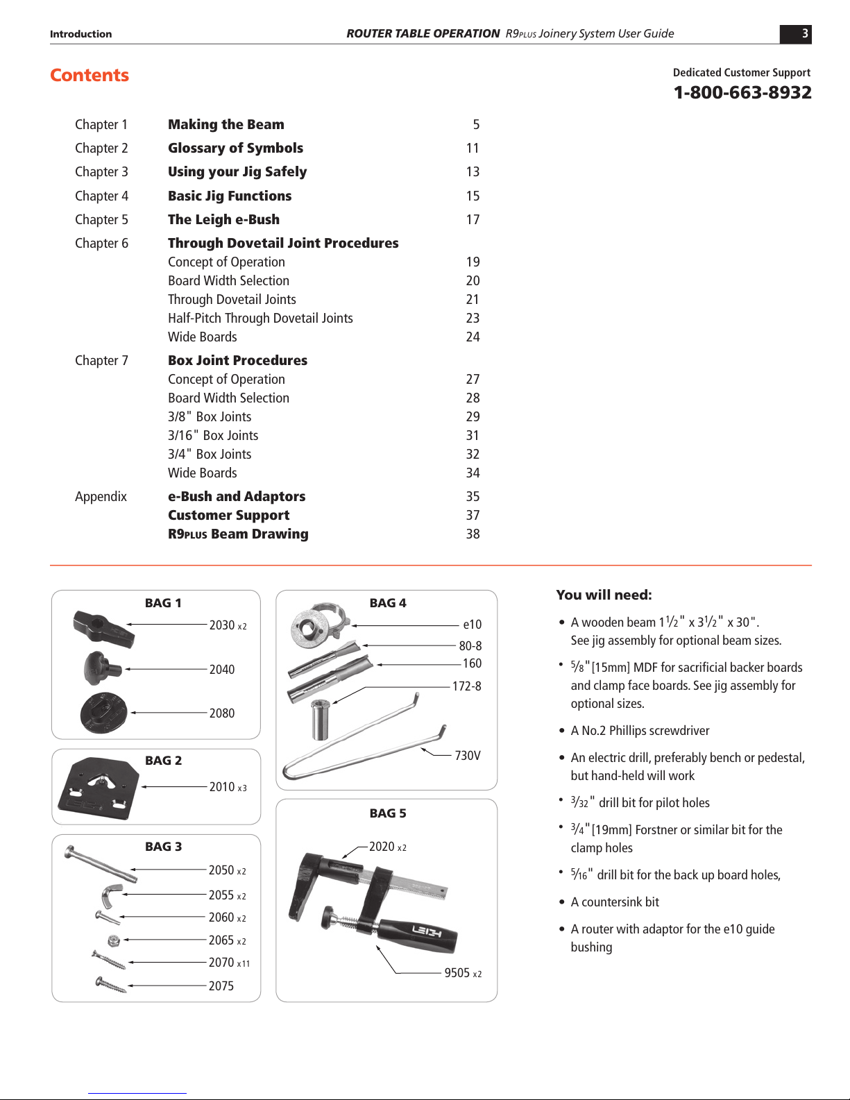
What’s in the Box:
PART NO. QUANTITY PART DESCRIPTION
2000 1 R9PLUS Template
2090 1 User Guide
BAG 1
2030 2 Latches
2040 1 Glide
2080 1 Side Stop
BAG 2
2010 3 Pin Plates
BAG 3
2050 2 Beam Assembly Screws, ¼"-20 x 2¾"
2055 2 Beam Assembly Wing Nuts, ¼"-20
2060 2 Latch Screws, Phillips 10-24 x ¾"
2065 2 Latch Nuts, Nyloc
2070 11 Wood Screws, Phillips Flat Head, No.8 x 1¼"
2075 1 Side stop Screw, Phillips Round Head, No.8 x ¼"
BAG 4
e10 1 e10 e-Bush (Guide Bushing)
80-8 1 Dovetail Bit, ½"-8º
160 1 Straight Bit, ½" Two Flute
172-8 1 Collet Reducer, ½" to 8mm
730V 1 Pin Wrench
BAG 5
2020 2 Clamp Locators
9505 2 F-Clamps
2000
2090
Page 3
33
ROUTER TABLE OPERATION
R9PLUS Joinery System User Guide
Introduction
e10
172-8
730V
80-8
160
2030 x2
2040
2080
2010
x3
2070 x11
2075
2065 x2
2060 x2
2050 x2
2055 x2
2020 x2
BAG 1 BAG 4
BAG 5
BAG 3
BAG 2
9505 x2
Contents
You will need:
s A wooden beam 1
1
⁄2"
x 3
1
⁄2"
x 30".
See jig assembly for optional beam sizes.
s 5
⁄8"[15mm]
MDF for sacrificial backer boards
and clamp face boards. See jig assembly for
optional sizes.
s A No.2 Phillips screwdriver
s An electric drill, preferably bench or pedestal,
but hand-held will work
s 3
⁄32"
drill bit for pilot holes
s 3
⁄4"
[19mm] Forstner or similar bit for the
clamp holes
s 5
⁄16"
drill bit for the back up board holes,
s A countersink bit
s A router with adaptor for the e10 guide
bushing
Dedicated Customer Support
1-800-663-8932
Chapter 1 Making the Beam 5
Chapter 2 Glossary of Symbols 11
Chapter 3 Using your Jig Safely 13
Chapter 4 Basic Jig Functions 15
Chapter 5 The Leigh e-Bush 17
Chapter 6 Through Dovetail Joint Procedures
Concept of Operation 19
Board Width Selection 20
Through Dovetail Joints 21
Half-Pitch Through Dovetail Joints 23
Wide Boards 24
Chapter 7 Box Joint Procedures
Concept of Operation 27
Board Width Selection 28
3/8" Box Joints 29
3/16" Box Joints 31
3/4" Box Joints 32
Wide Boards 34
Appendix e-Bush and Adaptors 35
Customer Support 37
R9PLUS Beam Drawing 38
Page 4
44
ROUTER TABLE OPERATION
R9PLUS Joinery System User Guide
R9PLUS Bit Selection
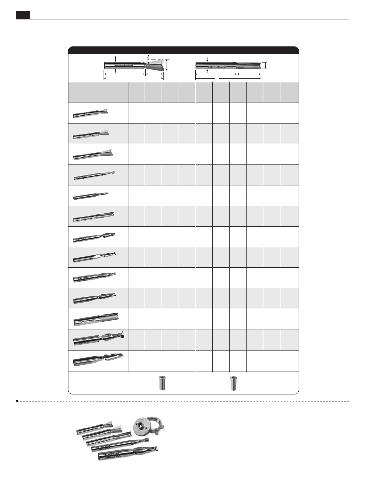
This chart shows all the bits that can be used on the R9PLUS.
R9PLUS BIT SELECTION
Leigh Bits
C
D
E
A B*
Bit
Diameter
F
Cutting
Depth
B
Max.
Diameter
A
C
Shank
D
Shank
Length
C
E
Overall
Length
D B
E
F
Angle
Use with
Straight
Bit No.
Use with
e-Bush
A
Use with
Collet
Reducer
Joint
Type
Introduction
70-8
75-8
80-8*
166*
166C*
140-8
170*
170C*
173*
3/8"
1/4" to
7/16"
1/2"
13/16"
3/16"
3/16" 2 1/2"5/8" 1/4"
5/16"
5/16" 3"7/8" 8mm,
5/16"
3/8" 3"1/8"- 1" 3/8"
8mm
1/2"
8mm
5/8"
8mm
(5/16")
(5/16")
2 1/4" 8º
1 3/4"
2 3/8" 8º
1 3/4"3/8" to
2 9/16" 8º
1 3/4"1/2" to
2 7/8"5/8" 1/4"
1 3/4"
1 3/4"
2 3/4" 172-8– – e7
1 3/4"up to1"8mm
1 3/4"
2 3/4" – – e7 172-8
1 3/4"up to1"8mm,
1 3/4" 172-375
140-8
170C
140-8
170C
180C
–
–
170
e10
170
e10
160
180
– –
e10
– ––
e10
– e7–
–
e10
172-8
172-8
172-8e10
172-8
Dovetail
Dovetail
Dovetail
Box
Box
Dovetail
Dovetail
Dovetail
Box
*Bits 80-8 and 160 included with the R9 Plus.
*Spiral upcut bits rout cleaner and faster,
leaving a smoother finish.
R9PLUS Accessory Kit
This kit offers great savings
over individual prices.
See leighjigs.com
173C*
160*
180*
180C*
3/8" 3"1" 3/8"
1/2"
1/2" 3 1/2"1 1/4" 1/2"
1/2"
1 1/4"
1 1/4"
up to
1/2"
1/2"
172-8
1/2" to 8mm collet reducer
1 1/4" long. For 8mm shank bits.
1 3/4"
1 3/4"up to
1 3/4"
1 3/4"
3" –
3 1/2" – – –
–
–
––
172-375
1/2" to 3/8" collet reducer
1 1/4" long. For 3/8" shank bits.
e10
e10
e10
e10
172-375
––
–
Dovetail
Dovetail
Dovetail
Includes:
70-8
3/8" dovetail bit (for through dovetails)
75-8
7/16" dovetail bit (for through dovetails)
140-8
5/16" straight bit (for half-pitch through dovetails)
e7
e-Bush (for 70-8, 75-8 for half-pitch through dovetails)
166
3/16" spiral upcut bit (for box joints)
173
3/8" spiral upcut bit (for box joints)
Box
Page 5
R9PLUS BENCH OPERATION
CHAPTER 1
Making the Beam
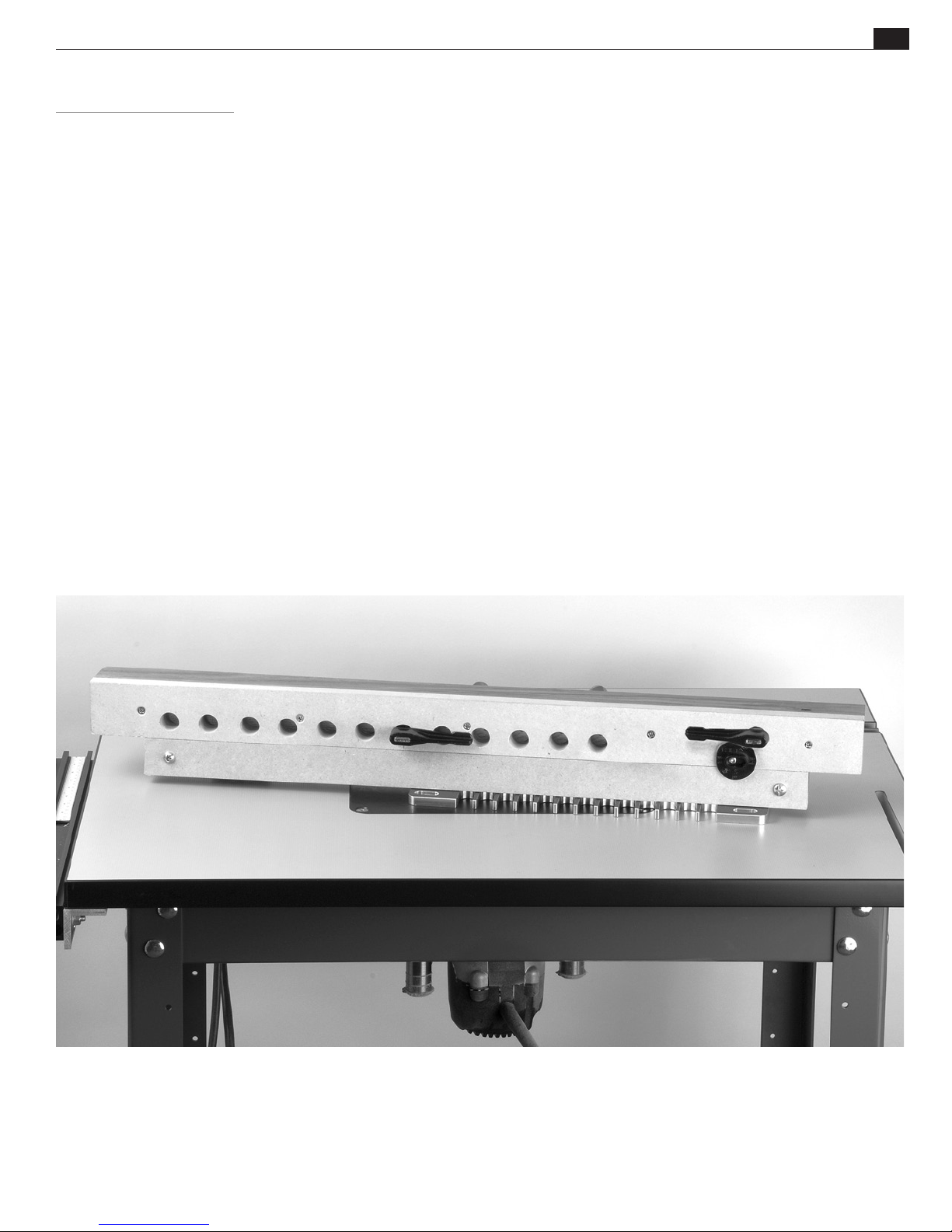
The heart of the R9PLUS Joinery System is the beam. A typical
beam, shown below, is 30"[762mm] long. A 30"[762mm]
beam can accommodate board widths of up to 18"[457mm].
Beams can be made shorter (minimum 20"[508mm]) or
longer, in 10"[254mm] increments. Because of the template’s
unique “step over” ability, beams can be made longer to suit
any width project. The beam is equally suited to router table or
bench operation.
The following instructions will guide you through the beam
making process. Care in building the beam will ensure great
joinery every time with the R9PLUS. In addition to these
instructions, a two page drawing, complete with all dimension
information, is provided at the end of the user guide.
55
Important: Please use this chapter’s step-by-step instructions
in conjunction with the technical drawing on pages 38-39 of
the Appendix.
Page 6
66
A
B
C
D
B
C
A
E
A
B
C
C
A
B
Important: Please use these step-by-step instructions in conjunction with the technical drawing on pages 38-39 of the Appendix.
Chapter 1
ROUTER TABLE OPERATION
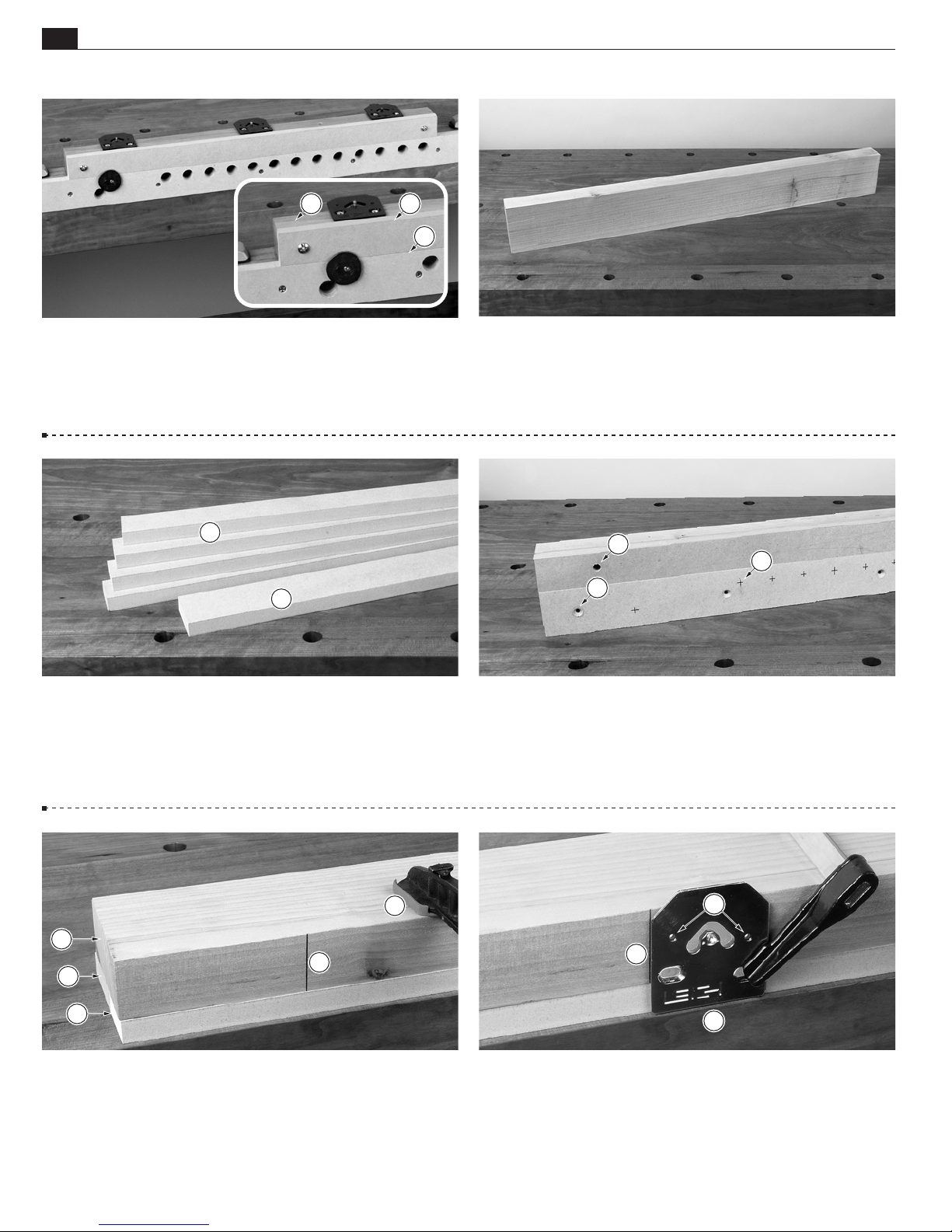
1-1 The beam assembly consists of the main beam
sacrificial backer boardand the clamping surface. The
R9PLUS Joinery System User Guide
1-2
, the
Start with a straight, flat and square 30"[762mm] length
of wood, 11⁄2" x 31⁄2" x 30"[35mm x 89mm x 762mm].
Making The Beam
clamping surface and sacrificial board are made from commonly
available 5⁄8"[15mm] MDF (optional 3⁄4"[19mm]). Hardwood or
softwood may also be used.
B
A
1-3 Cut a piece of MDF 30" long and 2
1
⁄8" wide [762mm
x 54mm]. This will be your clamping surface. Then cut
your sacrificial boards 11⁄2" x 30"[35mm x 762mm]. You may
want to cut a number of extra sacrificial boards now to use as
replacements.
1-4
Lay out the mounting screw holesand clamp holesas
per the drawing on pages 38-39. Drill and countersink the screw
holes on the clamping surface. Drill the 5⁄16"[8mm] holesin
the sacrificial board. This piece can be reversed and flipped four
times to use up all four surfaces.
1-5
This procedure is critical to the accuracy of the jig.
Before attaching the MDF boards to the beam, use each pin plate
as a drill guide. First, mark a line 41⁄2"[114mm] in from the end
of the beam and square it across. Next, stack the clamping
surface, sacrificial board and beamnear the edge of the
workbench and clamp in place.
1-6
Clamp a pin plate with its wide straight side flush to the
flat bench surfaceand its side edge on the line. Using
the 2 small holesin the pin plate as a drill guide, drill two
3
⁄32"[2,5mm] pilot holes 1"[25,4mm] deep.
Page 7
Making The Beam
ROUTER TABLE OPERATION
A
R9PLUS Joinery System User Guide
"
7
A
Chapter 1
B
77
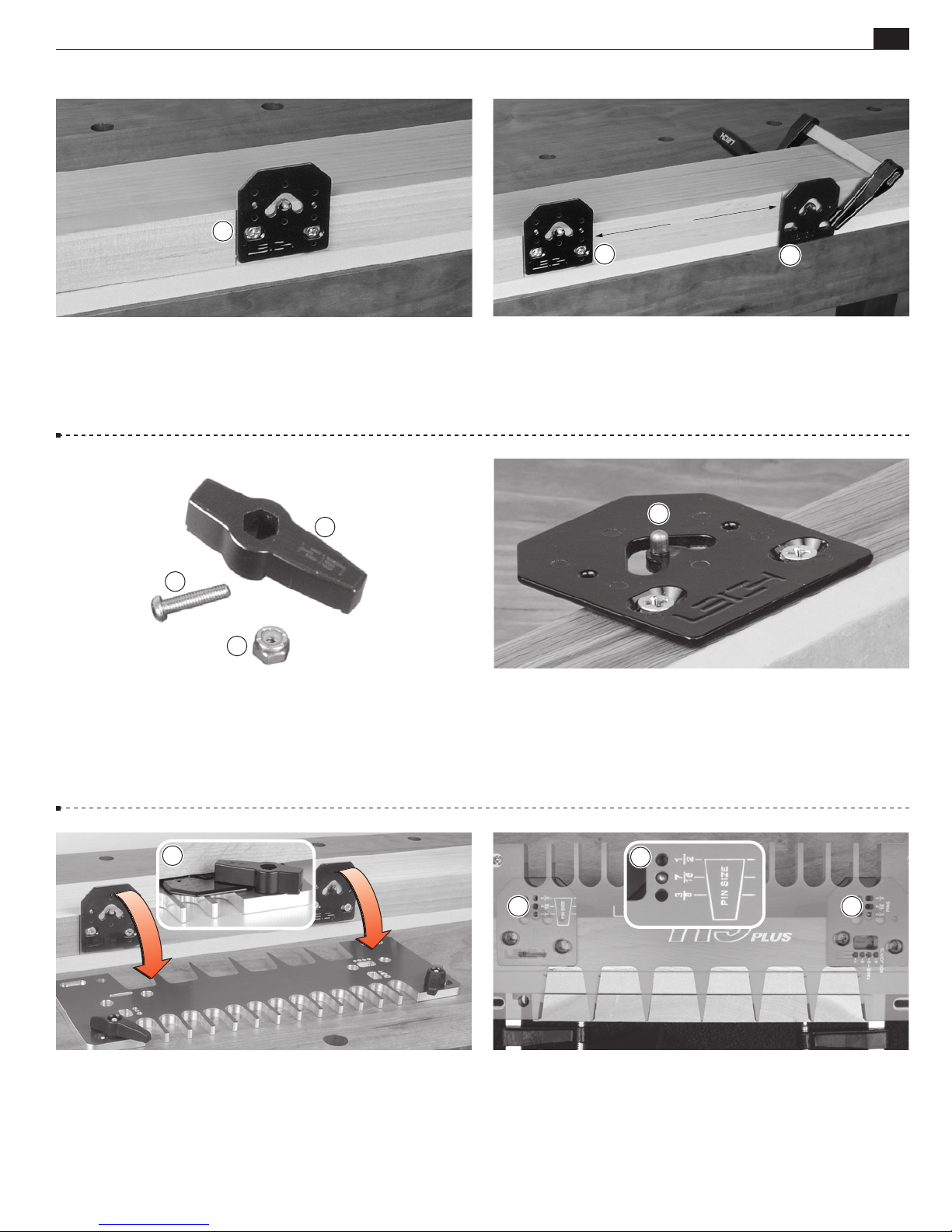
1-7 Use two No.8 x 1
lightly
attach the first pin plate with its left edge flush to the
1
⁄2"[38mm] wood screws (included) and
marked line.
C
A
B
1-9 Assemble the Latches There are three parts to each
latch assembly: the latch screw, the nyloc nutand the plastic
latch . Press the nyloc nut into the hexagon opening in the top
of the plastic latch with the white nylon insert facing up. Next,
screw in the latch screw from the bottom of the latch. Do not
tighten the screw at this time.
1-8 Square a second line across the beam board exactly 7"
[178mm] from the right edge of the first pin plate. Clamp
the second pin plate flat on the workbench and against the
line. Repeat the drilling and attaching procedure as before.
Repeat this procedure for each successive pin plate.
A
1-10 Pin Plate “Pin” The template has positioning holes
that allow it to sit perfectly on top of the raised pinof each
pin plate.
A
1-11 Attach the latches to the keyhole slots and turn to engage
the pin plates. Adjust the latch screw tension so that the
latches are stiff to turn onto the plates (as seen from underside
of template).
A
A A
1-12
Mount the template on the left pair of pin plates using the
7
⁄16"[11mm] pin position.
Page 8
88
Chapter 1
ROUTER TABLE OPERATION
R9PLUS Joinery System User Guide
Making The Beam
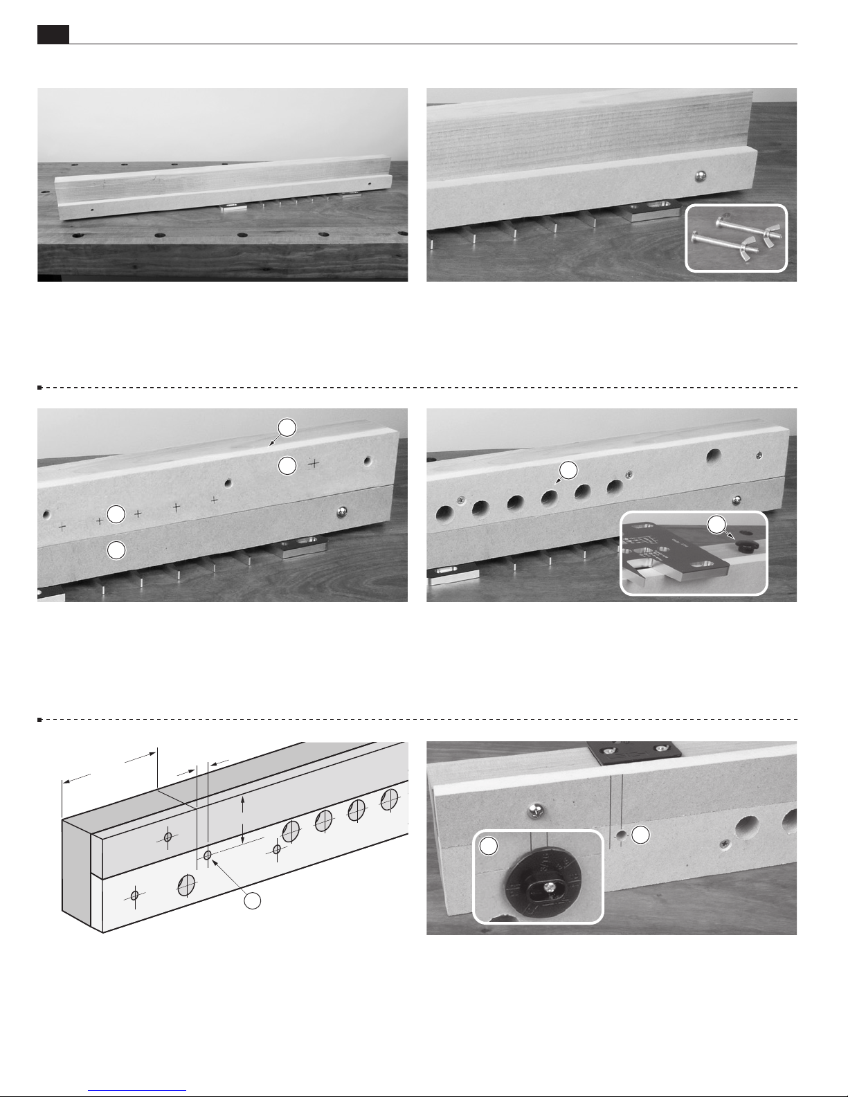
1-13 Turn the assembly upside down. Take a piece of the
predrilled sacrificial board and lay it flush on the template.
B
A
C
D
1-15
Place the clamping surfaceagainst the beam. Be sure
the clamp hole layout marksare next to the sacrificial board.
Screw the clamping surface to the beam through the countersunk
holes.
1-14 Using the two
5
⁄16"[8mm] holes as drill guides, drill
two 5⁄16"[8mm] holes through the beam. Attach the sacrificial
board at the left end with a ¼-20 machine screw and wing nut.
Then move the template to its second position and install the
second screw.
A
B
1-16
Clamp Holes Drill all 3⁄4"[19mm] clamp holessquare
to the beam, through the clamping surface and beam. Next,
drill two holes (as per beam drawing), 5⁄16"[8mm] diameter and
9
⁄16"[14mm] deep, for the table glide(used for router table
operation only).
[8mm]
"
16
/
2
/
1
4
[114mm]
"
5
[47mm]
"
/8
7
1
1
x 5/
dia.
"
6
[8mm x 8mm]
5/1
A
1-17 Side Stop Positioning Create layout lines as indicated
above for the sidestop. Note: Be precise. Side stop positioning
is very important.
6
deep
"
B
A
1-18 Using a Brad Point or Forstner bit, counter bore a
5
⁄16"[8mm] hole, 3⁄8"[9,5mm] deep for the side stop hub.
Then, using a 3⁄32"[2,5mm] bit, drill a pilot hole for the side
stop mounting screw. Attach the side stop to the beam with the
provided No.8 x 11⁄4"[30mm] round head screw.
Page 9
Making The Beam
A
ROUTER TABLE OPERATION
B
A
C
A
A
R9PLUS Joinery System User Guide
º
90º90
Chapter 1
99
1-19
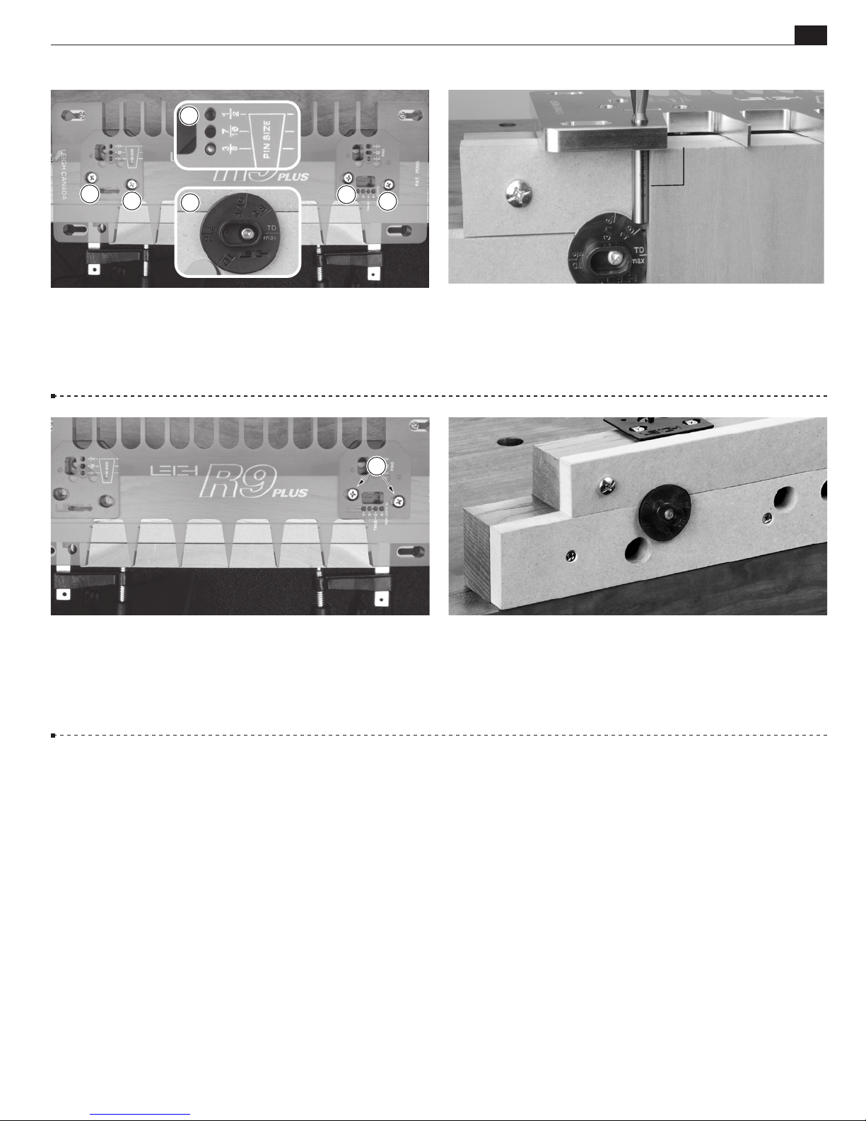
The template will now be used to precisely position the pin
plates. Slightly loosen all pin plate screwsjust enough so that
the pin plates can move side to side. Position the template on the
pin plates in the 3⁄8"[9,5mm] position. Set the side stop to the
TD Max position.
A
1-21
Gradually tighten the second pin plate screwsmaking
sure the template is not binding on the pins. Move the template
to the second position and repeat the procedure with the third
pin plate.
1-20 Clamp a square board against the side stop and flush
under the template. Insert the shank of the No.80-8 bit into
the 5⁄16"[8mm] hole in the template. Move the template and pin
plates laterally until the shank of the bit just touches the edge of
the board. Now tighten the first pin plate.
1-22
Optional Hold-down for Bench Use
Notch out the
ends of the beam in order to clamp beam assembly to a bench
and use in hand-held router mode.
■
Important: The beam may expand or contract with humidity changes. Use the
3
⁄8"[9,5mm]
ho les to adjus t th e pin pla tes as r equired .
Page 10

1010
Chapter 1
ROUTER TABLE OPERATION
R9PLUS Joinery System User Guide
Making The Beam
Page 11
R9PLUS ROUTER TABLE OPERATION
CHAPTER 2
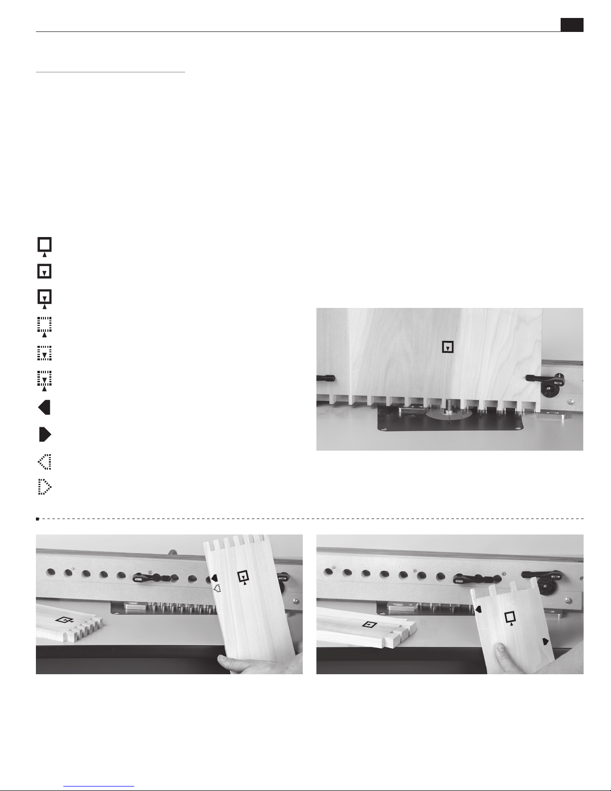
Glossary of Symbols
Which Way Around Should the Board Go?
The following symbols/icons are used throughout this user guide.
They indicate which side of a board faces out (toward you, the
operator, when clamped in jig), which faces are in or out when
assembled, and which edge goes against the side stop. Dashed line
icons indicate the other side of the board.
“Outside” of board
“Inside” of board
“Either side“ of board
1111
“Outside” of board (on other side of board)
“Inside” of board (on other side of board)
“Either side“ of board (on other side of board)
“This edge” against side stop
“This edge” against side stop
“This edge” against side stop (on other side of board)
“This edge” against side stop (on other side of board)
2-1
Icons such as the one above indicate which side of the board
faces out (toward you, the operator) when clamped in jig, and
which faces are in or out when assembled.
2-2 Box joint boards are clamped against the beam both “face
in” and “face out” for alternate end cuts. With box joints, the same
side edge always goes against the side stop.
2-3
Note:
Because through dovetail pin and tail boards face
only one way, both side edges are (alternately) used against the
side stop.
Page 12

1212
Chapter 2
ROUTER TABLE OPERATION
R9PLUS Joinery System User Guide
Glossary of Symbols
Page 13
1313
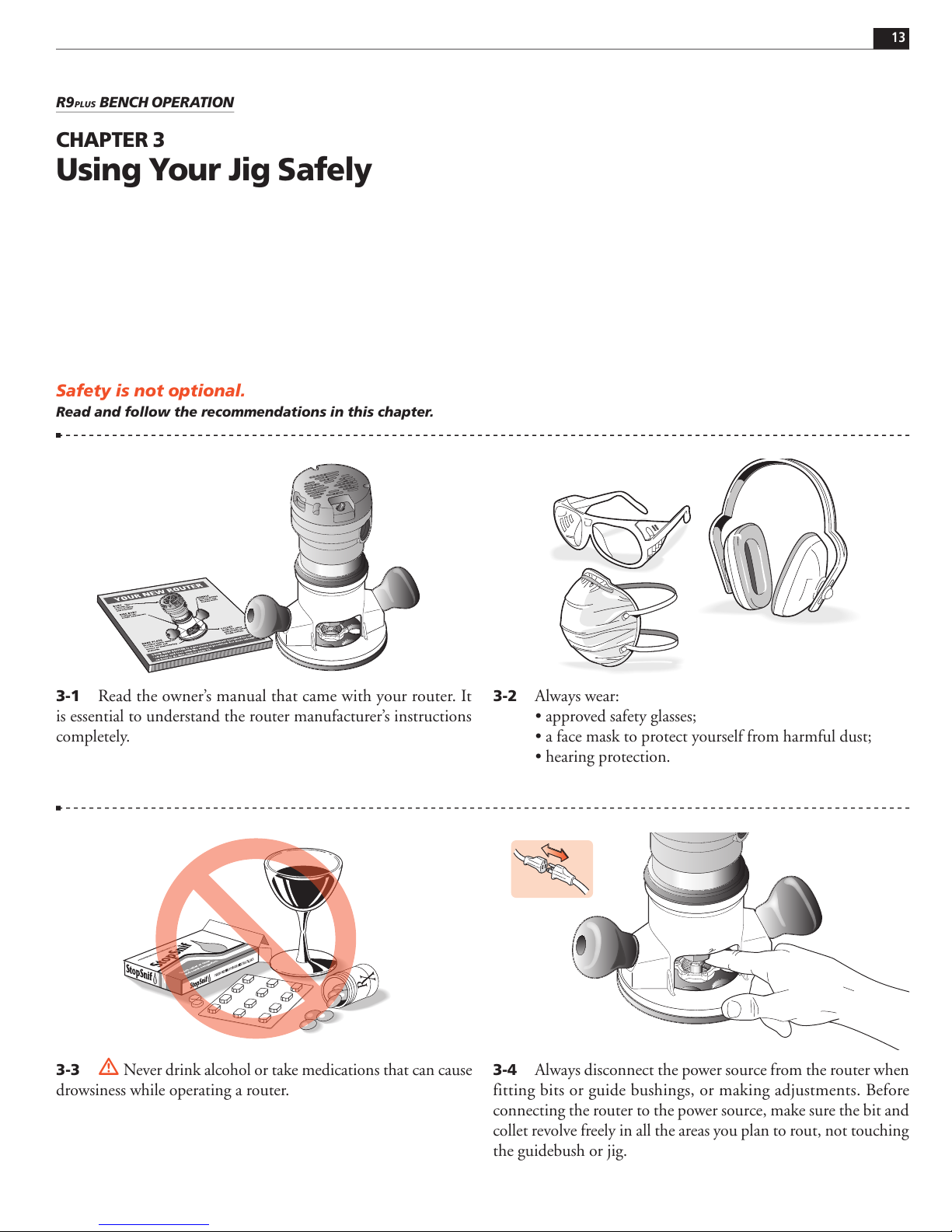
Safety is not optional.
Read and follow the recommendations in this chapter.
R9PLUS BENCH OPERATION
CHAPTER 3
Using Your Jig Safely
3-2 Always wear:
ÊUÊ>««ÀÛi`ÊÃ>viÌÞÊ}>ÃÃiÃÆÊ
ÊUÊ>Êv>ViÊ>ÃÊÌÊ«ÀÌiVÌÊÞÕÀÃivÊvÀÊ>ÀvÕÊ`ÕÃÌÆÊ
ÊUÊi>À}Ê«ÀÌiVÌ°
3-1
Read the owner’s manual that came with your router. It
is essential to understand the router manufacturer’s instructions
completely.
3-4
Always disconnect the power source from the router when
fitting bits or guide bushings, or making adjustments. Before
connecting the router to the power source, make sure the bit and
collet revolve freely in all the areas you plan to rout, not touching
the guidebush or jig.
3-3
! Never drink alcohol or take medications that can cause
drowsiness while operating a router.
Page 14
1414
ROUTER TABLE OPERATION
R9PLUS Joinery System User Guide
Using Your Jig Safely
Chapter 3
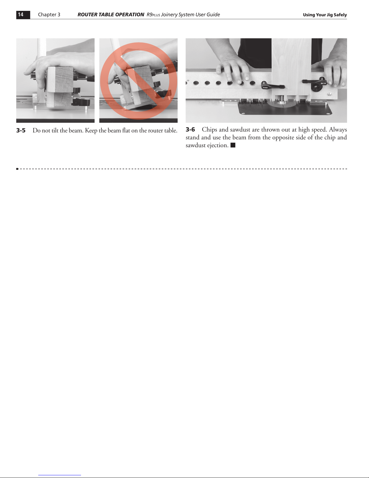
3-5
Do not tilt the beam. Keep the beam flat on the router table.
3-6
Chips and sawdust are thrown out at high speed. Always
stand and use the beam from the opposite side of the chip and
sawdust ejection.
■
Page 15
1515
R9PLUS ROUTER TABLE OPERATION
CHAPTER 4
Basic Jig Functions
Router Table Surface
Temp l at e O ri en t at io n
Pin Plate Positioning
Routing Position
Side Stop
Clamping Procedure
Note: The images in this user guide show the “action” side of the jig, however the operator stands behind the router table,
away from the chips and sawdust thrown off by the router bit.
B
C
A
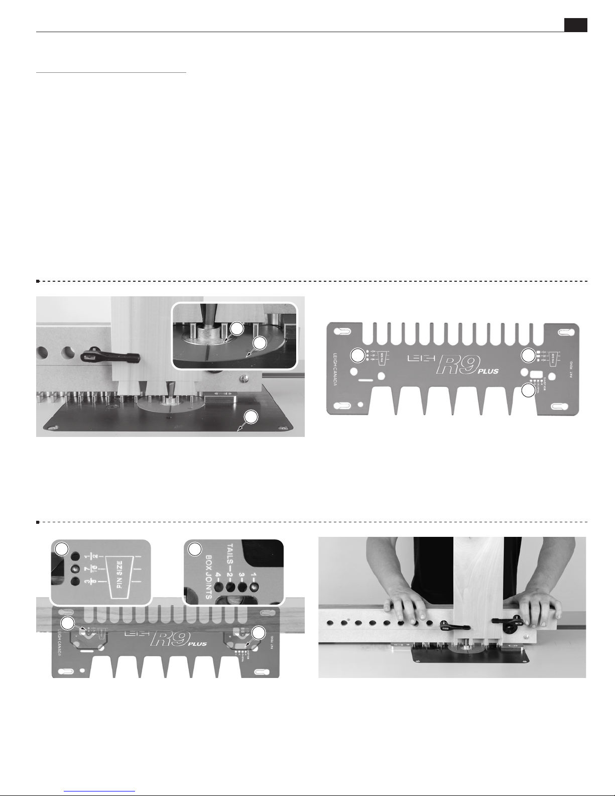
Router Table Surface
4-1
When using the R9
PLUS
on a router table, be sure there are
no height differences between the table and any lift mechanism,
guide bushingor bushing adaptor. The template must slide
smoothly over the table top.
A
B
A A
B
Templa t e Or i en t at i on
4-2 The engraved side of the template always faces up. Template
positioning holesare for through dovetail pins. Template
positioning holesare for through dovetail tails and box joints.
A
Pin Plate Positioning
4-3
The beam is positioned on the template using the pin plate
positioning holesand. Most illustrations will have an inset
showing the correct template pin position for the procedure.
B
Routing Position
4-4 Always begin routing from the left end of the jig when
viewed from the operator’s position.
Page 16
1616
Chapter 4
ROUTER TABLE OPERATION
R9PLUS Joinery System User Guide
A
Basic Jig Functions
Side Stop
4-5
The side stop is set on one of the five positions, depending
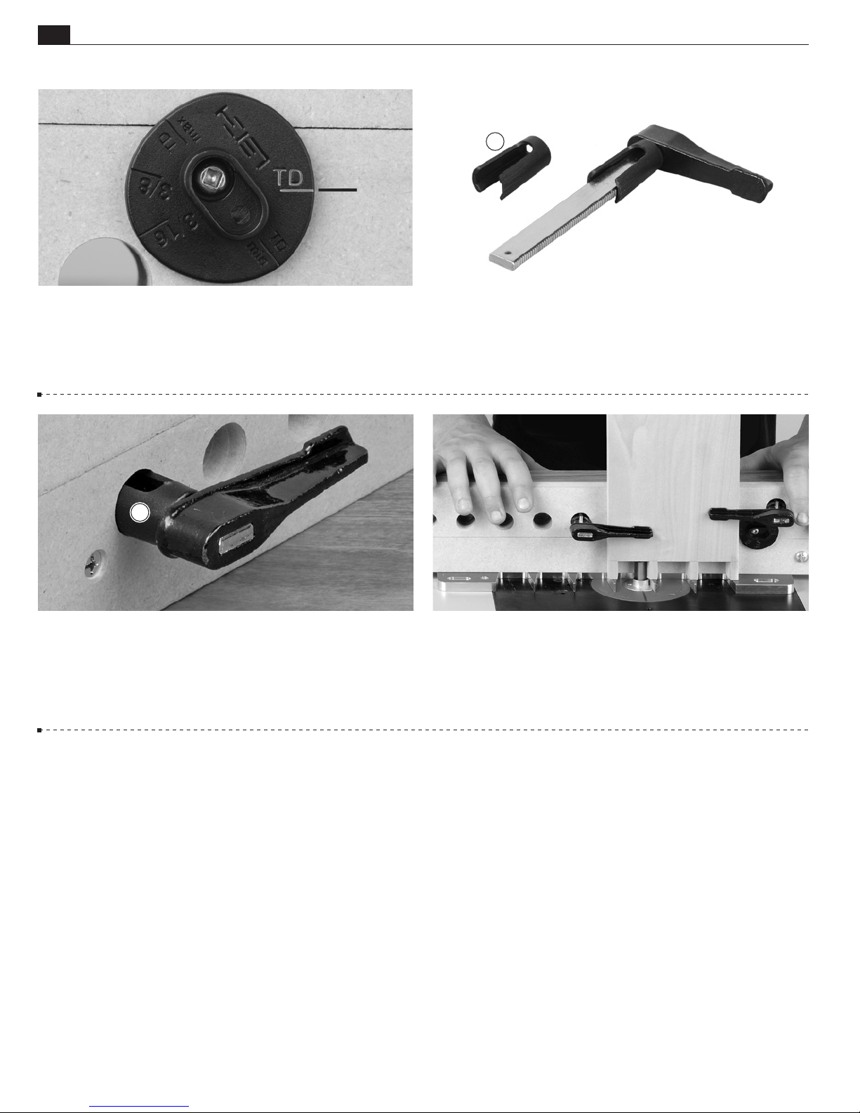
on the part or type of joint being routed. The side stop pictured
above is in the TD (Through Dovetails) mode.
A
4-7
Squeeze the tips of the clamp locatorand insert through
a clamp hole in the beam. Clamp locators hold the clamp arm
firmly in place while the clamp’s screw arm is attached from the
opposite side of the beam.
Clamping Procedure
4-6
Each of the F-Clamps included with the R9
PLUS
is fitted
with a clamp locator. The clamp locators are pressed onto the
clamp arm and should not be removed.
4-8
All boards are clamped against the side stop and flat on the
template. ■
Page 17
1717
A
R9PLUS BENCH OPERATION
CHAPTER 5
The Leigh e-Bush
Note: Normal tolerances with bits, guide bushings and router runout will generally produce poor fitting joints. The Leigh
e10 elliptical guide bushing solves this problem.
Joint Fit Adjustment
A
B
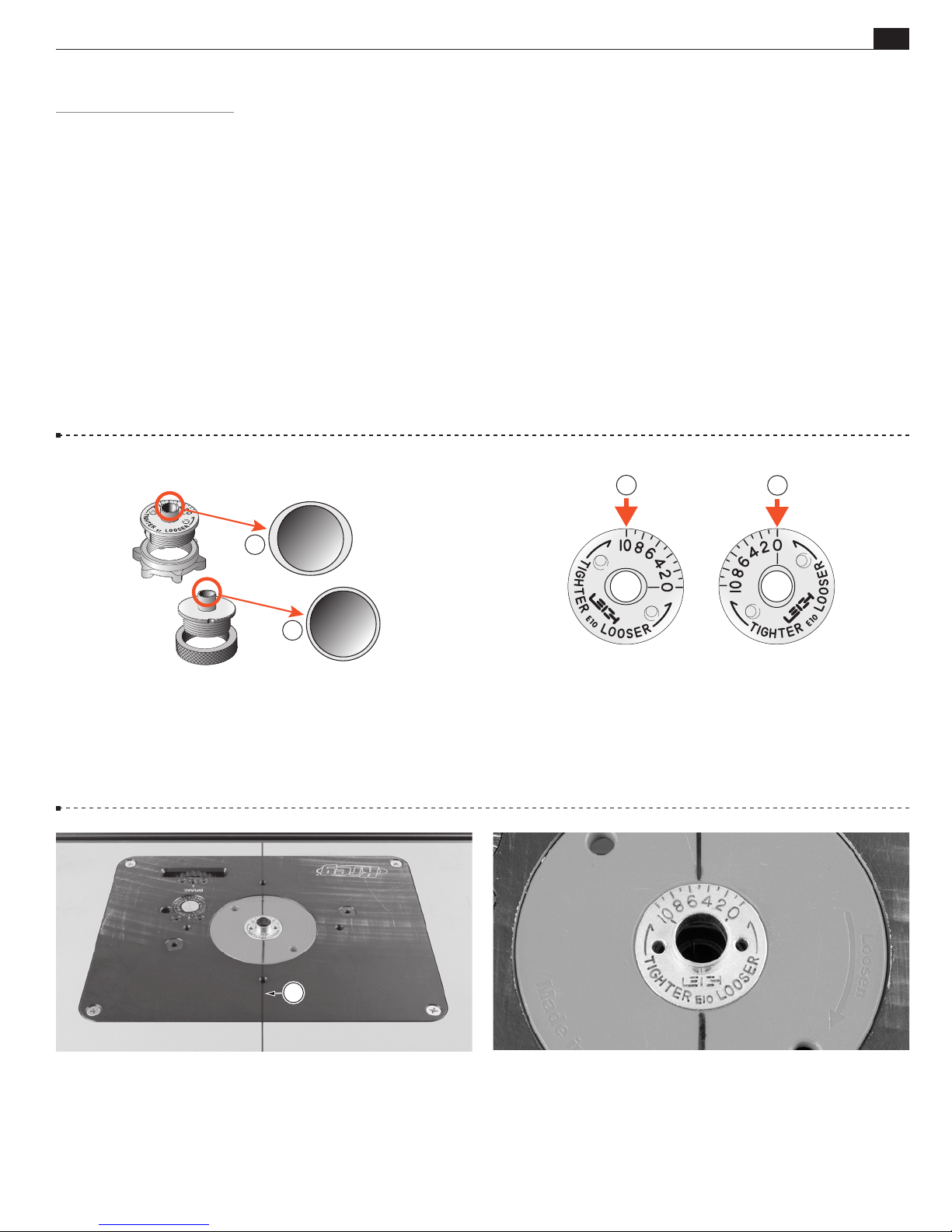
5-1 The Leigh e-Bush barrel is elliptical
, unlike plain
circular template guidebushes. When rotated, the effective
diameter of the barrel changes, allowing fit adjustments as small
as .001"[0.025mm]. The e10 e-Bush is included with the R9
PLUS
A
5-2
With the e-Bush turned to “10”in the base the active
B
“diameter” is increased, allowing less side-to-side movement,
resulting in smaller sockets and larger pins. Turning the e-Bush
to “0”allows more side-to-side router/bit movement and more
.
wood removal, producing larger sockets and smaller pins, and
thus a looser fit.
5-3
Make a small scratch line or permanent ink mark on the
router baseplateor guidebush adaptor at the 12 o’clock and
6 o’clock position. This will help you steer the template along
and between the guide surfaces.
5-4 All settings for the e-Bush will be aligned to the scratch or
ink marks on the router. The e-Bush will always be set on index
mark 5 as a starting point for dovetails and box joints.
Page 18
1818
5-5
Chapter 5
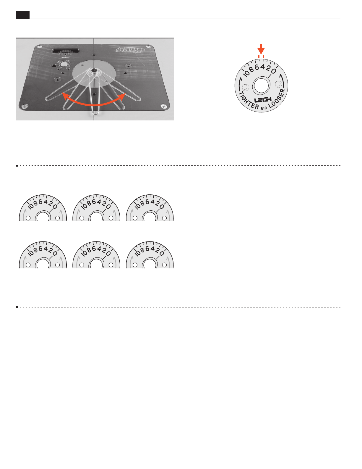
Adjust the e-Bush with the pin wrench. Markings on the
ROUTER TABLE OPERATION
R9PLUS Joinery System User Guide
e-Bush indicate which way to turn it for a looser or tighter fit.
The Leigh e-Bush
5-6 One division of the e-Bush changes the joint glue line by
0.002" [0.050mm]. A perfect fit will be established with one or
two test cuts.
5-6
After a good fit is established, record the e-Bush setting
for easy repeatability the next time.
■
 Loading...