

Page 1

Joi ning Tr adi tion w ith Today
Multiple Mortise
and Tenon Attachment
Multiple Mortise
and Tenon Attachment
LEIGH USER GUIDE
LEIGH USER GUIDE
Page 2
ii
Your New Leigh M2 Attachment
Congratulations! You now own the world’s
only jig for routing multiple mortise and tenon
joints; one of the most difficult joints to handcut is made simple with the M2.
The M2 is an optional attachment for the Leigh
Dovetail Jigs: 24" [610mm] models D1258,
D1258R, D3, D4 and D4R. Most illustrations
in this guide show the M2 mounted on the
D4 jig but the instructions are identical for
all the D4R and all earlier D series jigs.
Important: Inches and Millimetres
Leigh makes the M2 attachment in two models;
inch or metric. Text and illustrations in this
Leigh English-language user guide indicate
dimensions in both inches and millimetres.
Dimensions are indicated in text and illustrations with inches first, followed by millimetres
in square brackets.
Example:
3
⁄4" x 51⁄2" x 8" [20 x 140 x 200mm]
Do not be concerned if the inch/millimetre
equivalents are not always exact. Just use the
dimensions which apply to your jig.
Where finger assembly or template scales
overlay an illustration, the inches scale
will be at the top, the millimetres scale will
be at the bottom. Only the right “active” half
of the scales are illustrated. Setting positions
are indicated in this guide with a red line.
On the jig, the lines are black.
General views of the scales will usually
show inch markings.
2
1
3
We recommend that you first mount the M2
on your Leigh Jig, carefully following the
instructions in the first section of this manual.
Then read the rest of the manual, following
along with the basic functions and principles
of operation before you try to do any actual
joinery routing. By all means, cut a few practice
joints in scrap boards before you use the M2
to rout a precious workpiece!
If you have any questions that are not answered
in the manual, please call the Leigh customer
support line.*
*See Appendix III – Customer Support
Page 3

iii
Glossary of Symbols ........................................................................................................ iv
CHAPTER 1 – Assembly and Mounting ....................................................... 1
CHAPTER 2 – Using Your Attachment Safely .............................................. 7
CHAPTER 3 – Adjusting the Finger Assembly ......................................... 13
CHAPTER 4 – How Routers with Guidebushes Work ............................ 19
CHAPTER 5 – Basic Jig Functions ..................................................................23
CHAPTER 6 – Wood Preparation ....................................................................31
CHAPTER 7 – The Multiple Mortise and Tenon Joint ............................35
CHAPTER 8 – Operations Procedures for Mortises .............................. 39
CHAPTER 9 – Operations Procedures for Tenons .................................. 49
CHAPTER 10 – Beyond the Basics..........................................................................59
Appendix I – Guidebush and Cutter Selection ..........................................63
Appendix II – Parts List ......................................................................................69
Appendix III – Customer Support ....................................................................73
C O N T E N T S
Page 4

Glossary of Symbols
The Leigh M2 Attachment can be in any one
of three modes, depending on what part of
the joint is being routed. Each finger assembly
scale has its own mode icon, identifying that
joint part. You will also find the mode icon in
the top left hand corner of most illustrations,
indicating which finger assembly mode to use.
Sometimes a mode icon will be used to identify
a board.
Mode and Scale Icons
Mortises
Tenon (first side of tenons)
Tenon (second side of tenons)
iv
G L O S S A RY O F SY M B O LS
How to Read the Symbols
To help you understand the instructions and
illustrations in this manual, we have used a
number of international symbols, plus a few
special ones of our own. They are all explained
below. You needn’t worry about memorizing
these symbols now, because they are repeated
quite frequently in the manual, and you will
soon get used to them.
Page 5
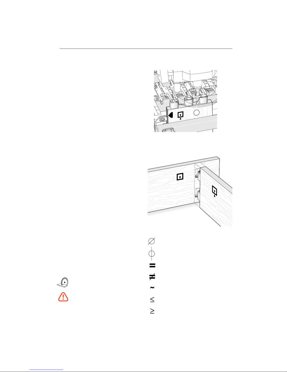
The following symbols indicate:
Left side of item (drawer, box,
case, etc.)
Right side of item
Top of item
Bottom of item
This edge against side stop
This edge against side stop
Sawcut allowance
Caution: use special care for this
operation
Reference in text
Which Way Round Should the Board Go?
In nearly all the illustrations we have indicated
which side of the board faces you when it is in
the jig, e.g., this tenon board can face either
inward or outward on the finished piece.
This indicates the side of the board that
will face outward on the finished
project.
This indicates the side of the board that
will face inward on the finished project.
This indicates a side that can face
either inward or outward on the
finished project.
Diameter
Centreline of board or layout
Equals
Does not equal
Approximately
Less than or equal to
Greater than or equal to
v
1
Page 6

G L O S S A RY O F SY M B O LS
vi
Page 7
Assembly and Mounting
CHAPTER 1
Page 8

A S S E M B LY A N D M O U N T I N G
Chapter 1 M2 U s er Gu i d e
2
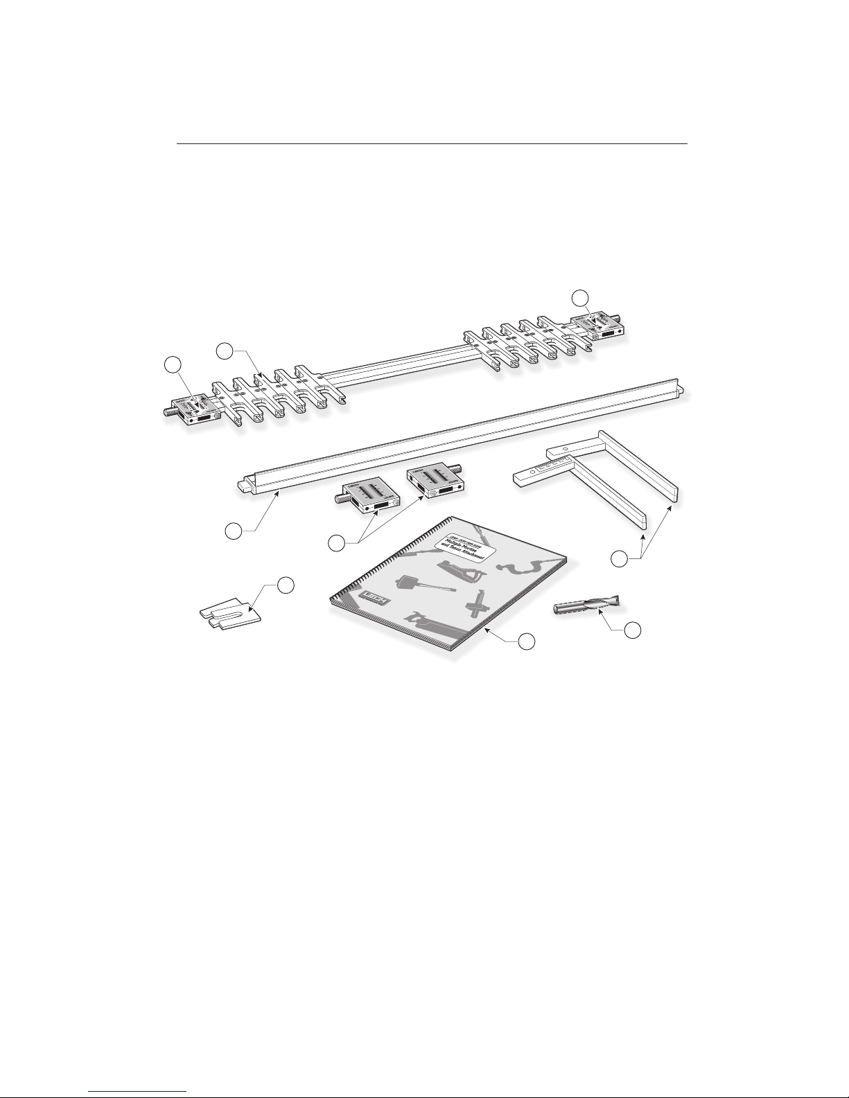
Make Sure You Have All The Parts!
Before you start to assemble your Leigh M2,
check to make sure you have received all the
required parts.
The carton contains:
1. 1 finger assembly on two bars
(10 pairs of fingers)
2. 2 scale assemblies for guidefingers
3. 1 fence assembly complete with two end
plugs
4. 2 scale assemblies for fence
5. 2 support brackets*
6. 1 standard cutter, 1⁄2"[12,7mm] spiral
upcut
7. 1 Leigh M2 user guide
8. 2 Side Stop Extensions
If any of these items are missing from your
jig, please notify your supplier or Leigh Industries
immediately.
*D4 and D4R jigs already have these brackets, so
these become spares.
Page 9
1
3
6
7
4
2
2
5
8
3
Page 10
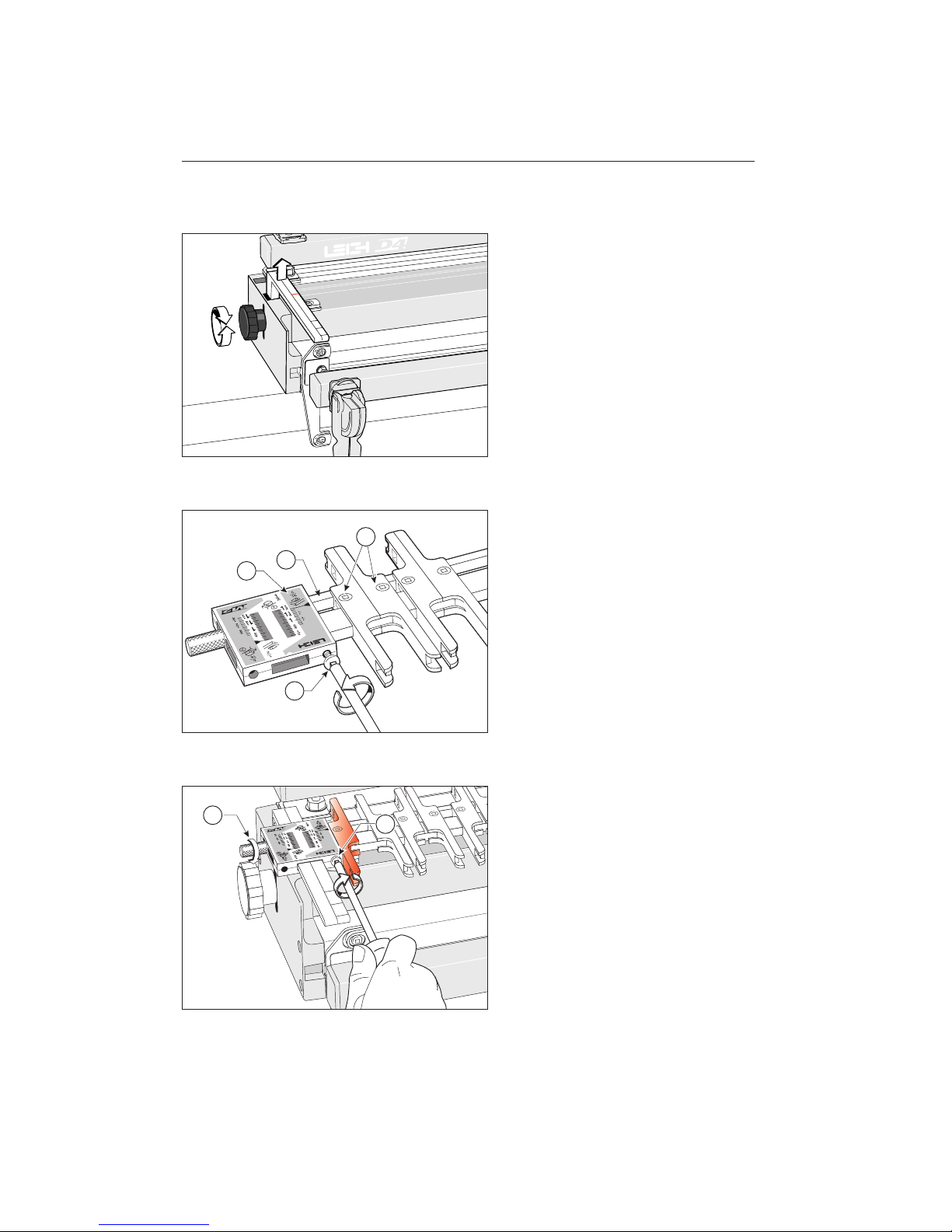
1-1
D1258, D1258R, and D3 jig owners:
Replace the short support brackets with
the extended M2 brackets. These are
marked LH to left, RH to right. Raise to
full height and tighten the knobs. Use these
new extended brackets for all dovetailing
or template jointing functions.
D4 and D4R jig owners: your M2 attachment may come with the extended support
brackets. Put these in your “spares” box.
Raise the support brackets to full height
and tighten the knobs.
1-2
Place the finger assembly on a bench with
finger screws upwards and the small
square bar away from you, and the 5⁄16"
[7,9mm]
mortise scale-
to the right
at both ends. Loosen the scale screws .
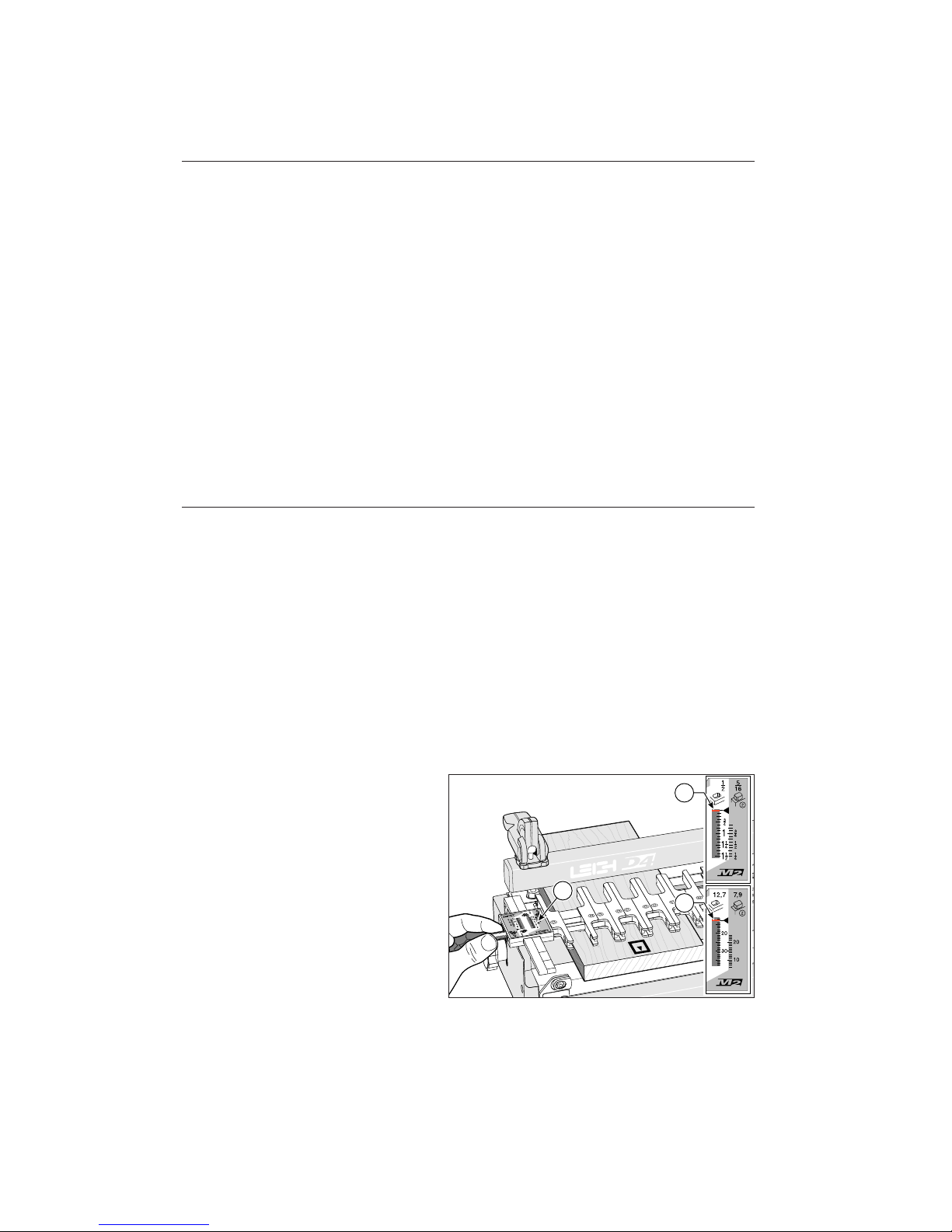
1-3
Slide complete finger assembly with loose
scales onto support brackets. Set scales at
say, 3⁄4" [20mm] on the 5⁄16" [7,9mm]
mortise scale and tighten thumb screws-.
Now tighten scale lock screws firmly with
Leigh screwdriver. Do not over-tighten. To
ensure correct alignment, follow this same
procedure whenever scales are removed from
finger assembly.
Move the outer finger on both ends out to
touch the scales (shown in red).
2
3
4
1
2
1
A S S E M B LY A N D M O U N T I N G
Chapter 1 M2 U s er Gu i d e
4
Note: Most illustrations in this guide feature the D4 model jig.
Page 11
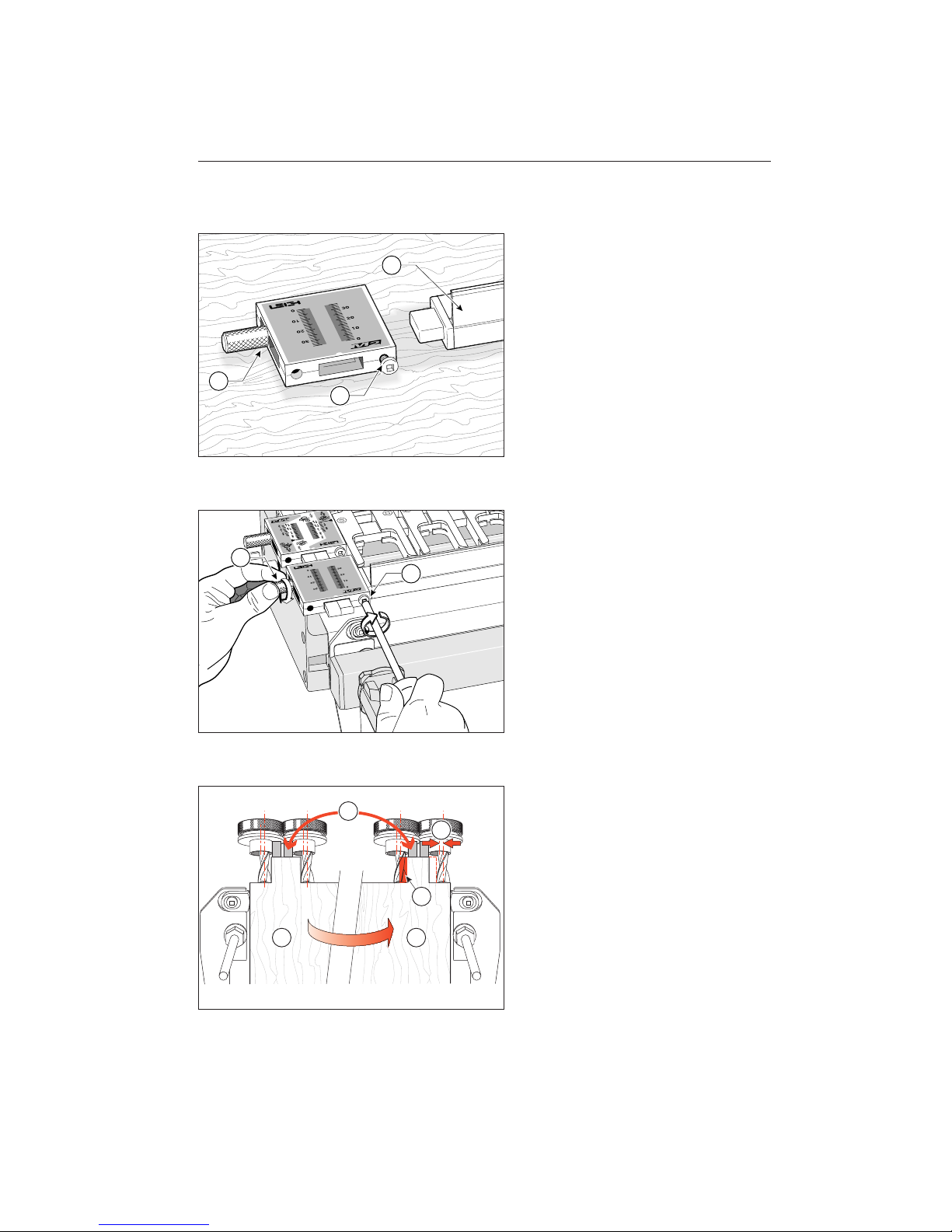
1-4
Place fence extrusion flat down on bench
with fence upright and towards you.
Slide tongue into left hand fence scale as
shown, with brass thumb screw outward
and away from you. Repeat for the right
hand scale but do not tighten fence scale
lock screws yet.
1-5
Slide complete fence assembly with loose
beam scales onto support brackets. Set
scales to the same reading at both ends
and tighten brass thumb screws . Now
tighten scale lock screws firmly with
Leigh screwdriver. Do not over-tighten.
To ensure correct alignment, follow this same
procedure whenever scales are removed from
fence.
1-6
Using the M2 requires a small modification
to your Leigh jig. Multiple tenons are routed
in two separate stages at both ends of the jig
…first on the left- and then, with the finger assembly and tenon board flipped end
for end …on the right-. In this second
position it is impossible to guarantee perfect
indexing between the guide fingers, side stops
and partly formed tenons-. This is mainly
caused by the cutter not being concentric to
the guidebush-.(greatly exaggerated in this
illustration).
1
2
3
5
2
3
1 2
2
4
3
Page 12
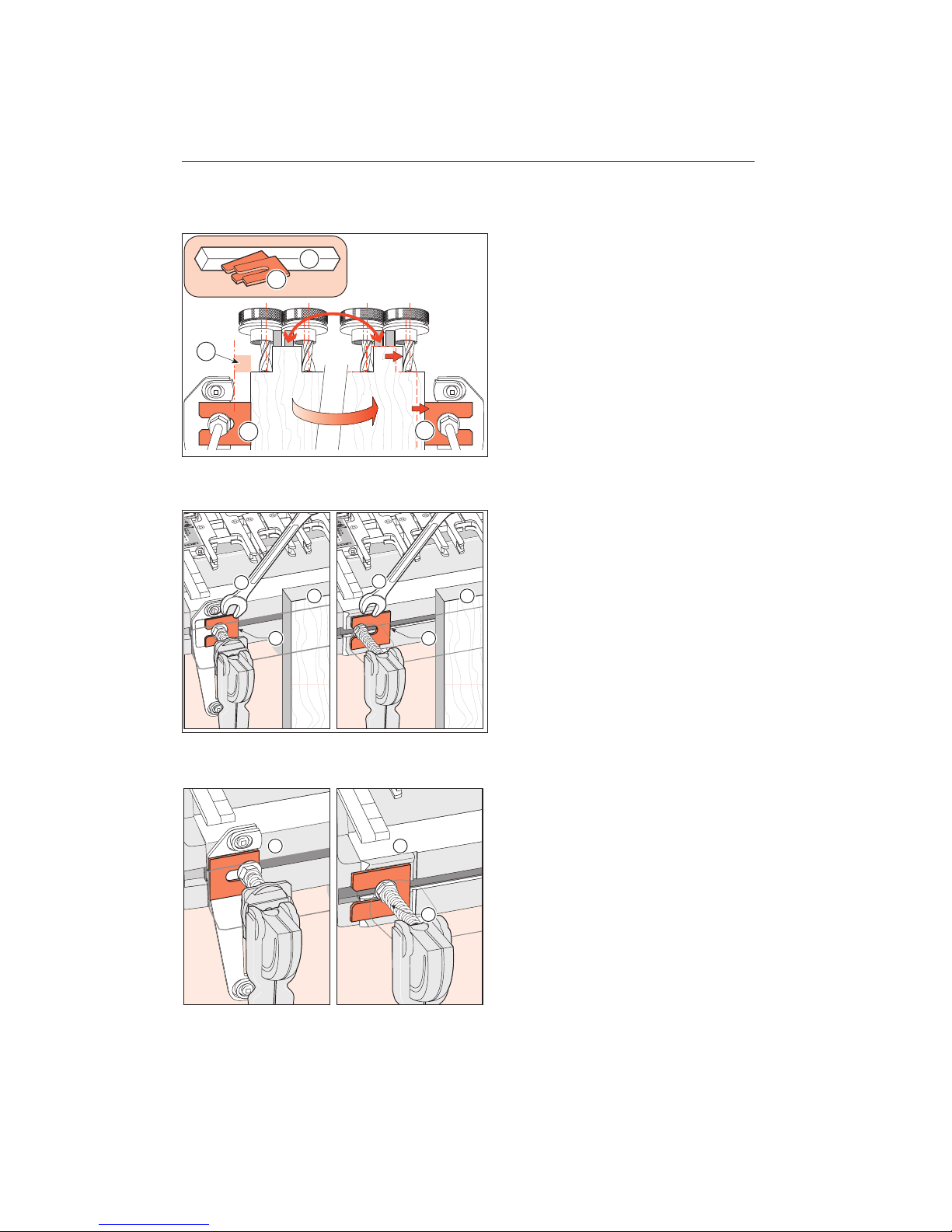
1-7
To solve this problem and correctly index
the side stops, we have provided two metal
sidestop extensions-. To complete the
modification, you will also need to cut a
simple 1⁄2"[12mm] square by 5"[125mm]
long wood “mortise block”-. The block
and extensions will allow adjustment to
compensate for any cutter to guidebush
eccentricity. The procedure is explained
later in this guide.
1-8
To install the extensions, lightly clamp a
board in the front clamp centre-. This
will maintain tension on the clamp bolts
and keep them in position while you attach
the extensions. Use a 1⁄2"[13mm] open end
wrench to loosen the two front clamp bolt
nuts- sufficiently to slide the extensions
beneath the washers. Lightly tighten the
nuts for now-.
1-9
When you’re not using the jig with the
M2:
On the D4 and D3 jigs turn the extensions
outward-.
On the D4R jig, the extensions can be
retracted-.
Always tighten the clamp nuts after setting
or retracting the extensions, .
1
1
1
2
2
2
3
1
2
3
1
1 2
3
A S S E M B LY A N D M O U N T I N G
Chapter 1 M2 U s er Gu i d e
6
Page 13
Using Your
Attachment Safely
CHAPTER 2
Page 14

U S I N G Y O U R A T T A C H M E N T S A F E LY
Chapter 2 M2 U s er Gu i d e
8
Chapter Foreword
Safety is not optional.
Read and follow the recommendations in
this chapter.
Page 15
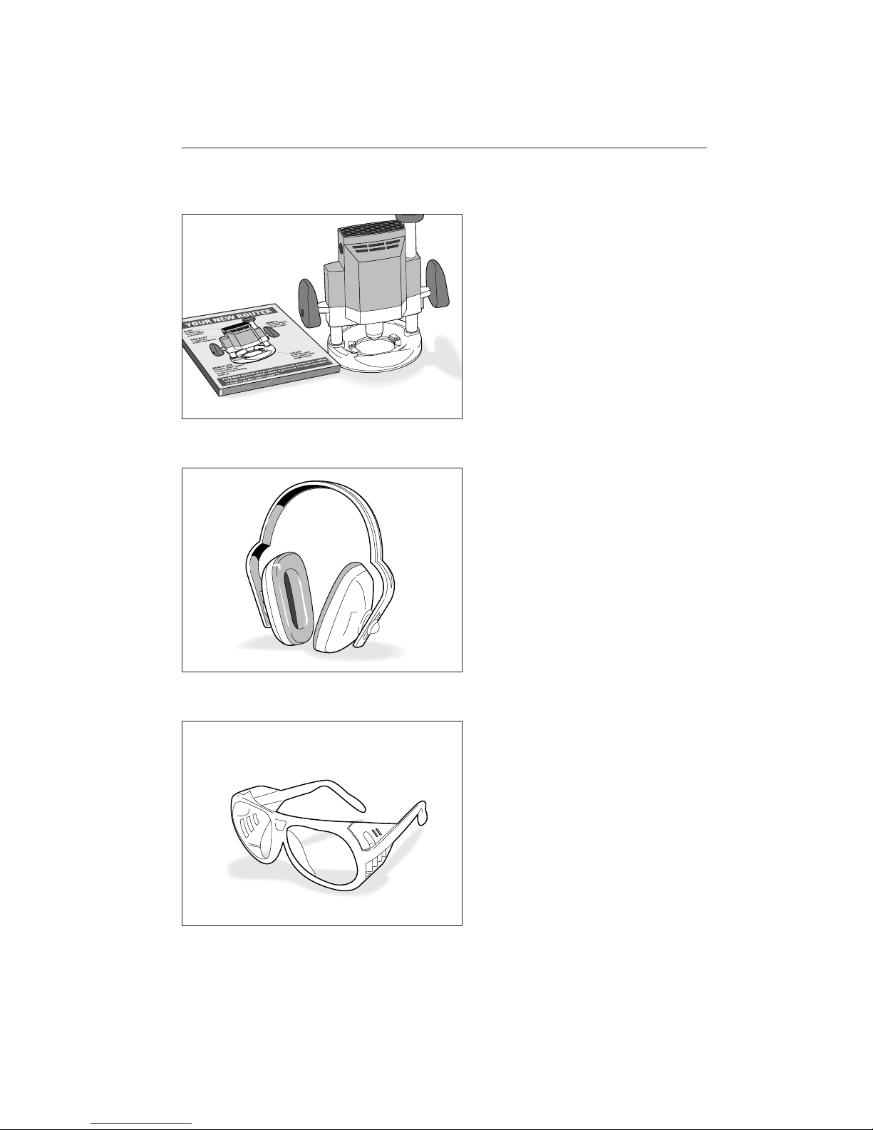
2-1
Read the owner’s manual that came with
your router. It is essential to understand
the router manufacturer’s instructions
completely.
2-2
Always wear hearing protection when using
a router.
2-3
Always wear approved safety glasses when
using a router.
9
Page 16
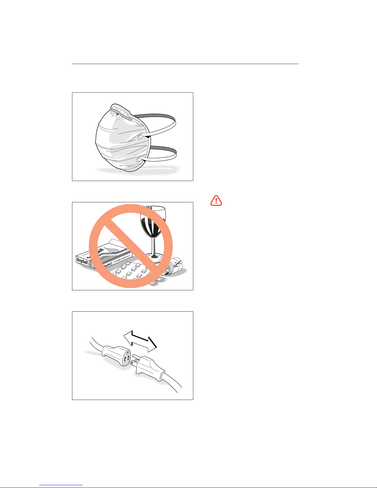
2-4
Protect yourself from harmful dust by wearing a face mask.
2-5
Never drink alcohol or take medications
that may cause drowsiness when you will
be operating a router.
2-6
Always disconnect the power source from
the router when fitting cutters or guidebushes, or making adjustments.
U S I N G Y O U R A T T A C H M E N T S A F E LY
Chapter 2 M2 U s er Gu i d e
10
Page 17
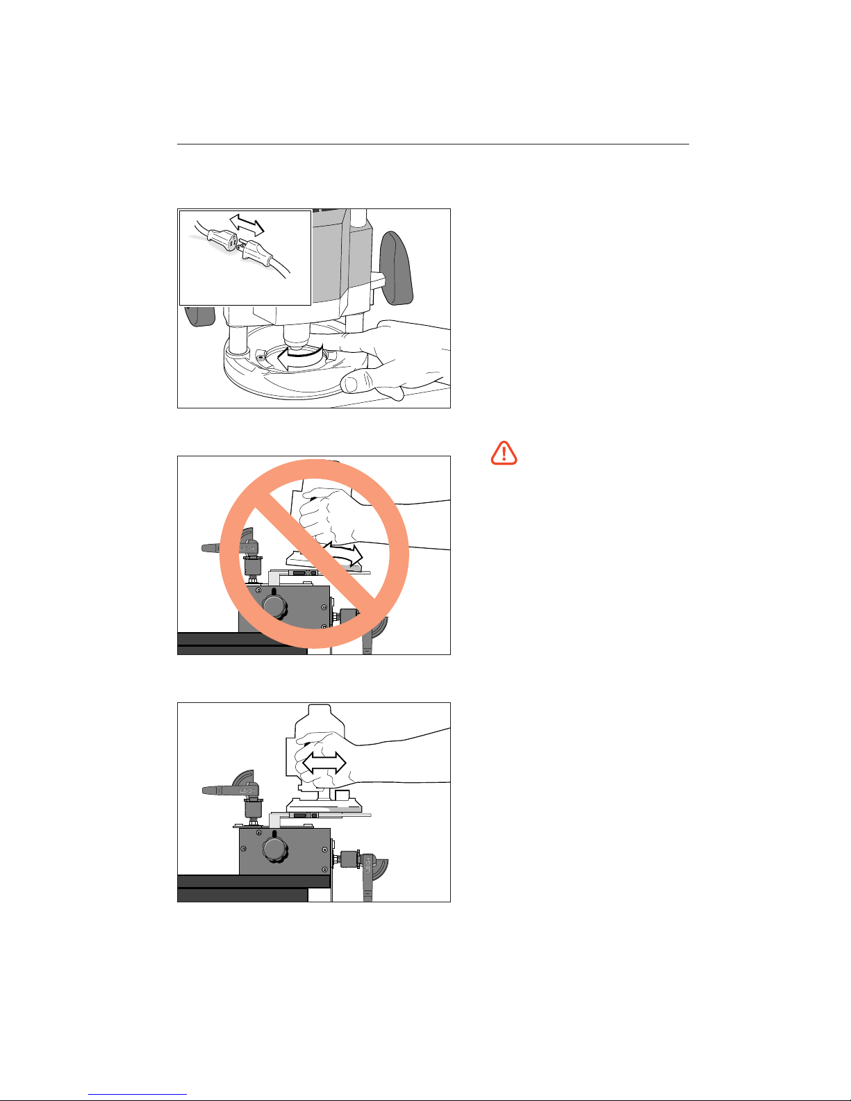
2-7
Before connecting the router to the power
source, make sure the cutter and collet
revolve freely in all the areas you plan to
rout, and the cutter does not touch the
guidebush or jig.
2-8
Do not tilt the router on the jig.
2-9
Keep the router flat on the jig assembly.
11
Page 18
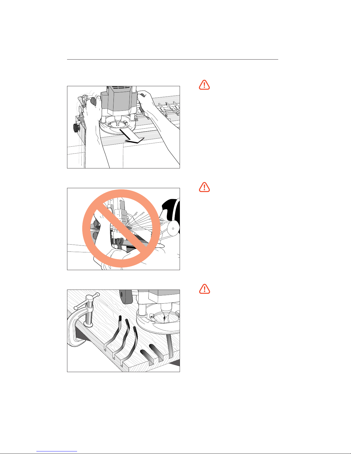
2-10
If you insist on removing the router from
the jig while it is still revolving, always pull
it straight off the jig horizontally, and do
not raise or lower the router until it is
completely clear of the jig.
An obvious exception is while routing mortises, which requires the plunge mechanism
to be raised before removing the router.
2-11
Do not rout at face level.
2-12
If you have never used your router before,
be sure to follow the router manufacturer’s
instructions for its use. Make plenty of
simple open-face practice cuts without a
guidebush before you try to use the router on the Leigh Jig. You must, of course,
always use a guidebush when routing on
the Leigh M2.
U S I N G Y O U R A T T A C H M E N T S A F E LY
Chapter 2 M2 U s er Gu i d e
12
Page 19
Adjusting the
Finger Assembly
CHAPTER 3
Page 20

A D J U S T I N G T H E F I N G E R A S S E M B LY
Chapter 3 M2 U s er Gu i d e
14
Chapter Foreword
The finger assembly is the heart of the
Leigh-M2. Spend a few minutes now
to familiarize yourself with these simple
adjustments.
Page 21
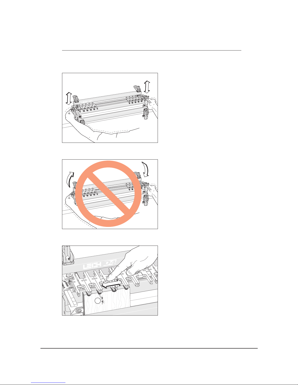
3-1
Practice with the finger assembly height
adjustment. Loosen the support bracket
knobs and hold them firmly. Raise and
lower the assembly evenly, keeping it level,
and tighten the knobs to lock it at various
heights.
3-2
Do not raise or lower one end of the finger
assembly at a time.
3-3
To practice adjusting the guidefingers, put
a board in the front clamp. Always raise the
finger assembly slightly above the spacer
board and/or workpiece, approximately
1
⁄16"[2mm]-. This allows the guidefingers
to move freely on the guidefinger bar. Move
the guidefingers by pushing on the middle
to slide them along the guidefinger bar.
15
Page 22
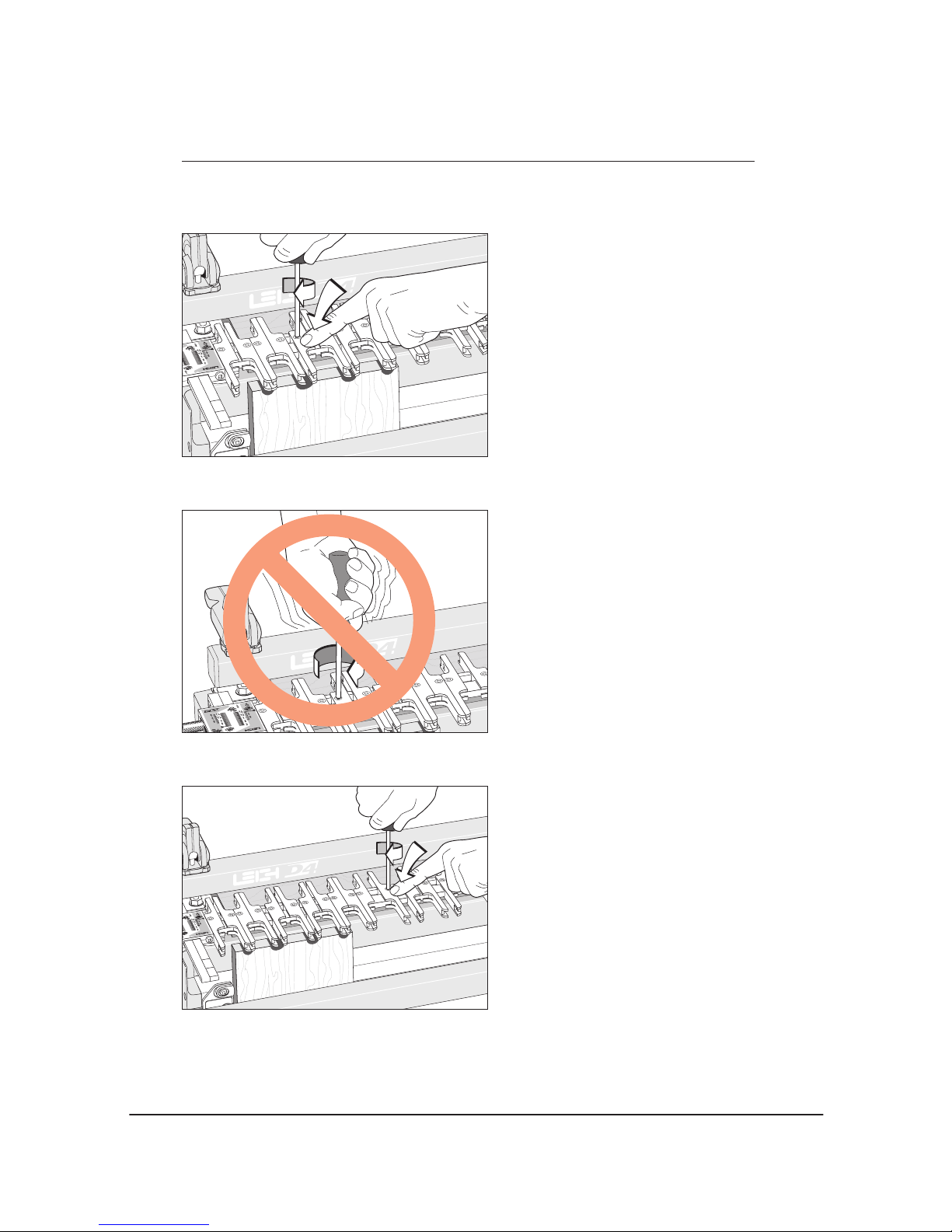
3-4
Loosen about half the guidefingers and
practice unlocking, moving, positioning
and relocking them. Always press on the
centre of the guidefinger when tightening
the screws.
3-5
Do not over-tighten the guidefinger lock
screws. The Leigh screwdriver provided
will give ample torque for easy lock-up
without strain.
3-6
Always tighten unused guidefingers before
routing, as router vibration may cause loose
screws and wedge nuts to fall out and be
lost.
A D J U S T I N G T H E F I N G E R A S S E M B LY
Chapter 3 M2 U s er Gu i d e
16
Page 23
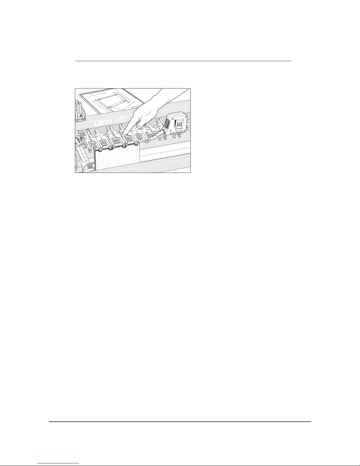
3-7
You can adjust the guidefingers by eye, or
by measurement to suit a set of plans.
17
Page 24

A D J U S T I N G T H E F I N G E R A S S E M B LY
Chapter 3 M2 U s er Gu i d e
18
Page 25
How Routers with
Guidebushes Work
CHAPTER 4
Page 26

H O W R O U T E R S W I T H G U I D E B U S H E S W O R K
Chapter 4 M2 U s er Gu i d e
20
Chapter Foreword
The guidebush is the vital link between
router and jig. Here’s how it works.
Page 27
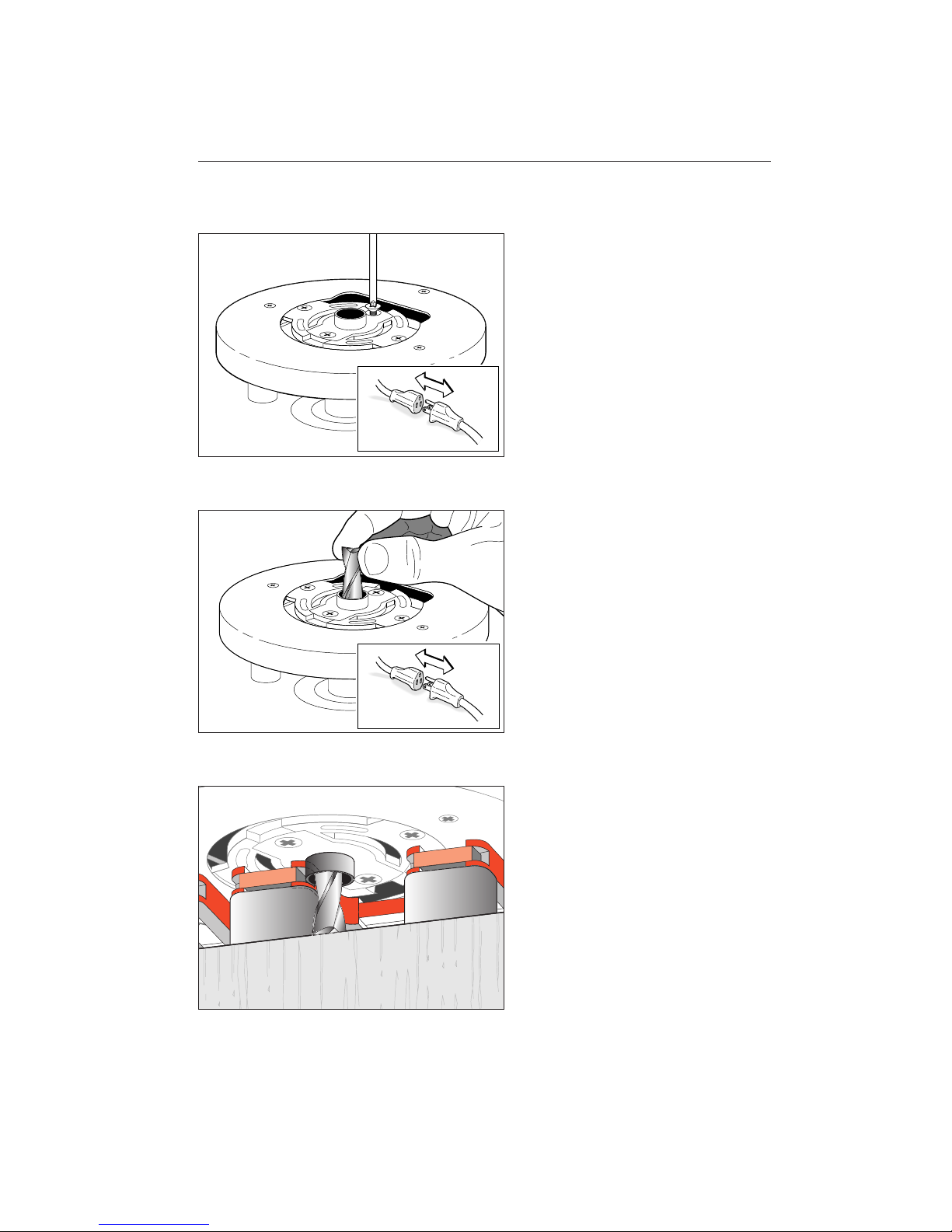
4-1
The guidebush attaches to the base of the
router and is fixed. It does not rotate.
4-2
The cutter or bit goes through the guidebush
and fits in the router collet or chuck.
4-3
The projecting part of the guidebush runs
along the side edge of a guide. The rotating
cutter cuts the wood only, and touches neither the guidebush nor the guide surface.
Note: 7⁄16" guidebushes in the 5⁄16" mode
should not project more than 1⁄4"[6,5mm]
from the router base. File to shorten as
required.
21
Page 28

H O W R O U T E R S W I T H G U I D E B U S H E S W O R K
Chapter 4 M2 U s er Gu i d e
22
Page 29
Basic Jig Functions
CHAPTER 5
Page 30
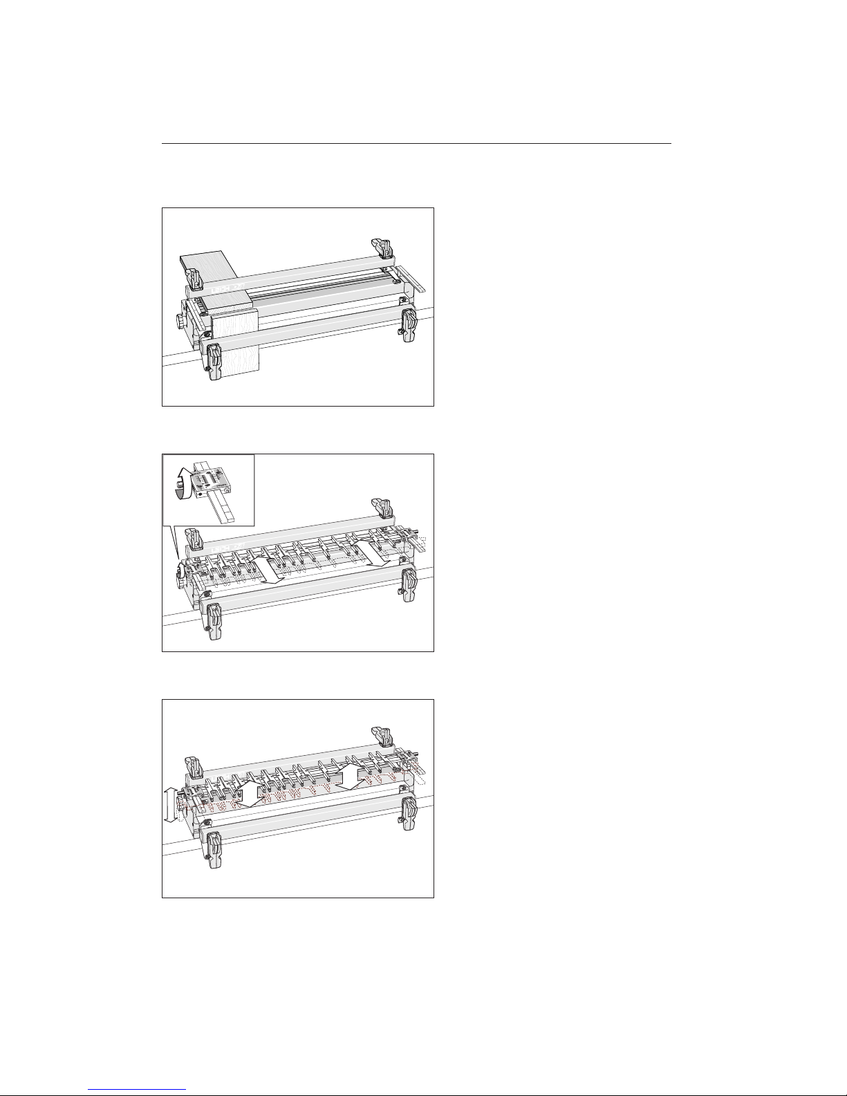
5-1
The two clamp bars hold workpieces
horizontally or vertically. The side stops
align the boards in the same position each
time.
5-2
The guidefinger assembly slides on to the
support brackets above the workpiece.
The finger assembly is adjusted in or out
using calibrated scales on each end to suit
different mortise and tenon sizes.
Note: The single rear indicator line on each
support bracket is for the finger assembly.
The front three lines are for the fence.
5-3
The finger assembly is raised or lowered
using the support brackets to suit different
thicknesses of horizontal boards.
B A S I C J I G F U N C T I O N S
Chapter 5 M2 U s er Gu i d e
24
Page 31
25
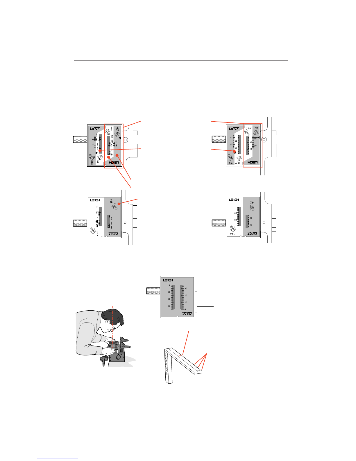
THE SCALE MODES
The Finger Assembly attaches to the support brackets in different modes to match the type of
joint you are cutting. Your jig will include either inch or millimetre scales as ordered.
This line is for the finger assembly scales.
The line is illustrated in red for clarity, but
is black on the jig.
The active scale is always on
the right of each scale assembly.
Only active scales are shown in
instructional illustrations.
The inactive scale is always on
the left of each scale assembly
and is upside-down.
Finger scales are colour coded:
Green background for 5⁄16"[7,9mm] modes.
Silver background for 1⁄2"[12,7mm] modes.
Each finger scale has its own
mode icon (a dra w i n g o f
the joint part made in that
mode).
The specific settings for each
scale are fully described in the
appropriate chapters.
These three lines are used only for
setting the fence scales. The lines only
show through the active scales.
Always read scales from directly overhead to avoid parallax problems.
The Fence scales are solid green.
The ruler increments are arbitrary and
used simply for fence parallel alignment.
1
INCHES MILLIMETRES
THE SUPPORT
BRACKETS
Page 32
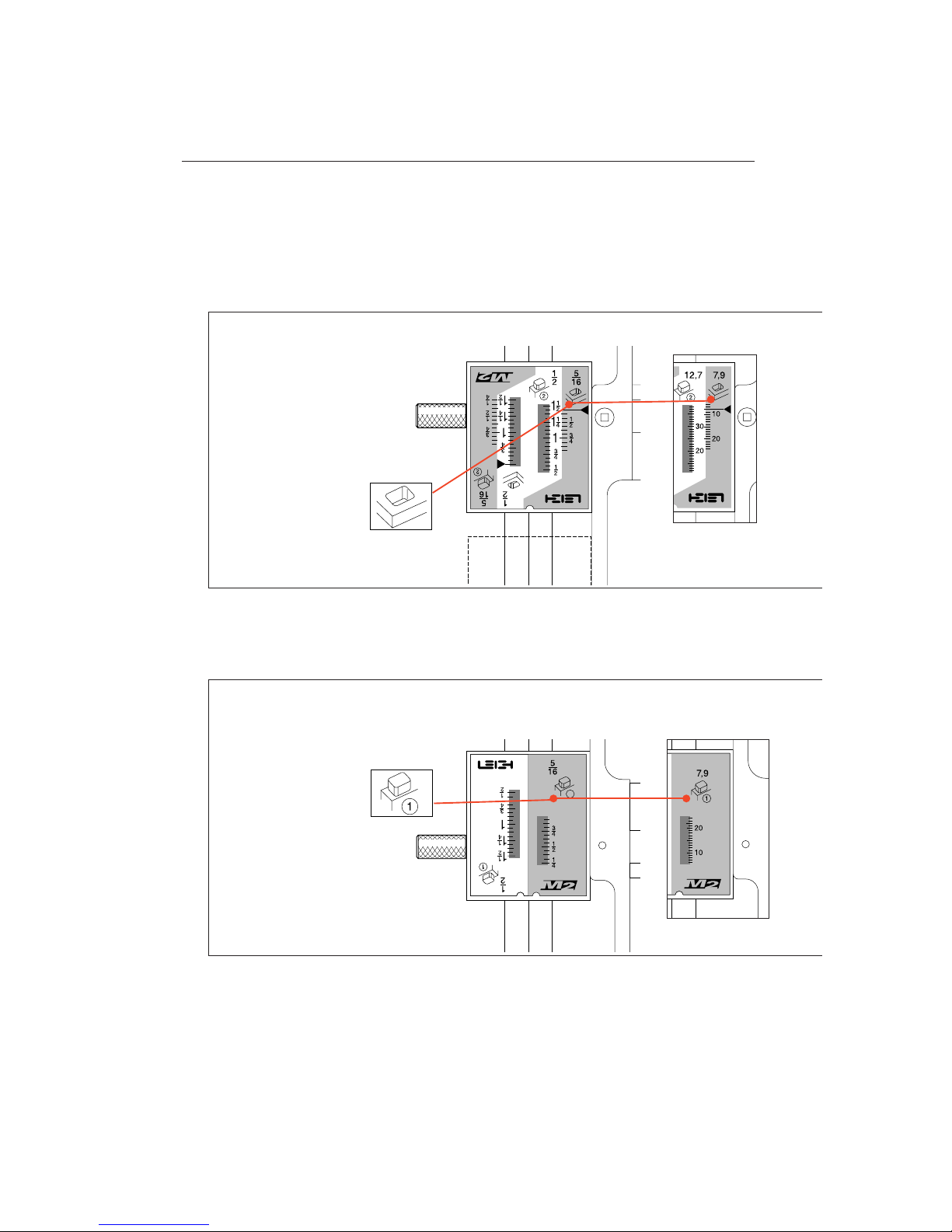
These illustrations show modes for 5⁄16"[7,9mm] cutter. Start with the Finger Assembly in the
5
⁄16"[7,9mm] mortise mode and without wood or router, follow these steps on your jig as a
dry run. Grasping the simple basic concept of operation will greatly assist you in understanding the instructions. Note: active guide surfaces (against which the guidebush runs) are illustrated
in red.
Start at the 5⁄16"[7,9mm]
MORTISE mode
MODE ICONS
Each illustration in this
manual includes the correct
mode icon for its
current instruction. Icons are
also used in the text.
Now the Finger Assembly is in
5
⁄16"[7,9mm]
TENON mode
ROTATE
Remove fence and rotate the finger assembly toward you 180°
B A S I C J I G F U N C T I O N S
Chapter 5 M2 U s er Gu i d e
26
1
CONCEPT OF OPERATION
1.
3.
2.
FLIP
Flip the finger assembly end-over-end 180°
4.
INCHES MILLIMETRES
INCHES MILLIMETRES
Page 33
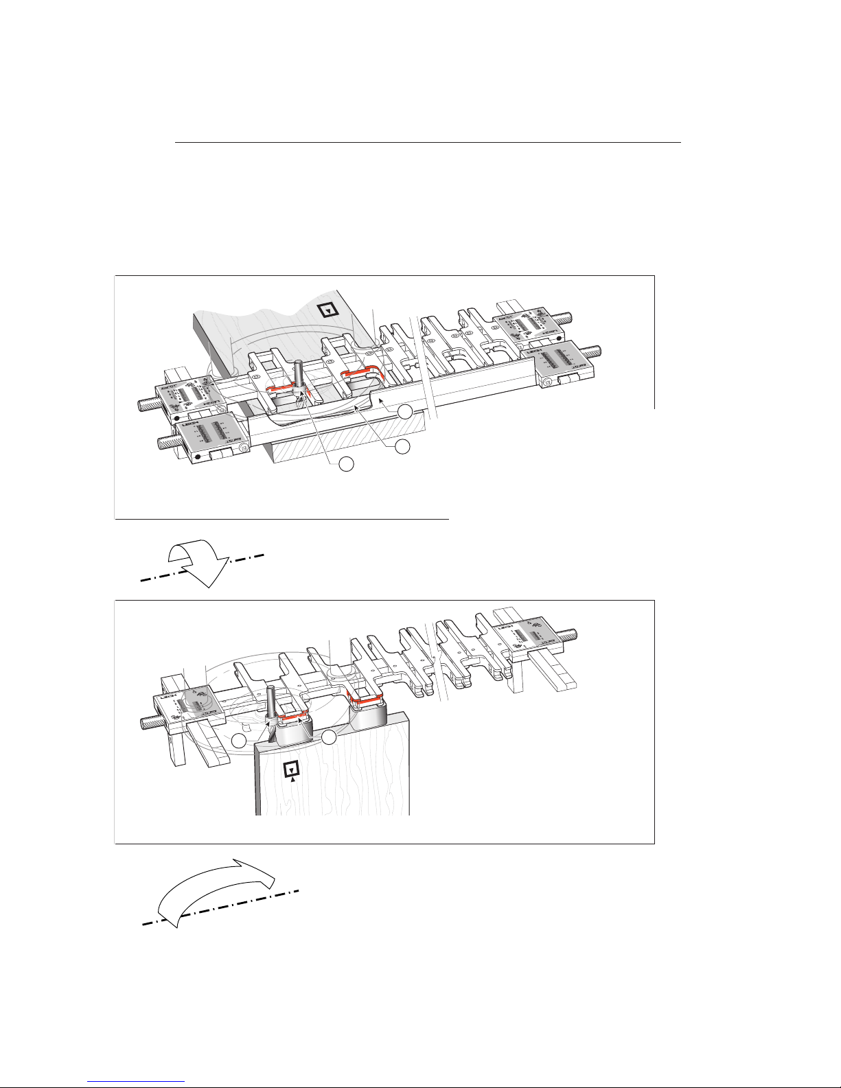
Mortise
The Guidebush controls the cut on three
sides of the mortise by running on a pair of
guidefingers and on the finger rail. The router
base controls the fourth side of the mortise
by running on the inside of the mortise fence
. The mortise board is clamped horizontally
under the guidefingers.
3
2
1
27
1
4
ACTIVE GUIDE SURFACES
ACTIVE GUIDE SURFACES
Tenon
The tenons are cut using the same router bit
and guidebush as used on the mortises.
The tenon board is clamped vertically under
the guidefinger. The guidebush controls
the cut by running around the guidefingers
and (where there is a gap), across the bridge
pieces .
Page 34
B A S I C J I G F U N C T I O N S
Chapter 5 M2 U s er Gu i d e
28
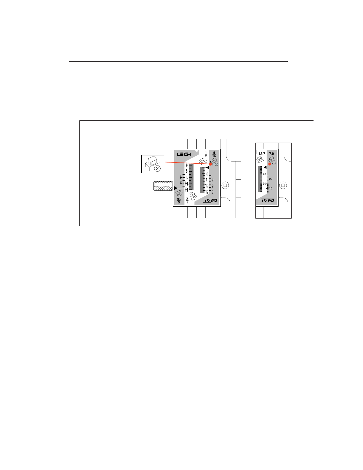
Finish in
5
⁄16"[7,9mm]
TENON mode
CONCEPT OF OPERATION
5.
Page 35
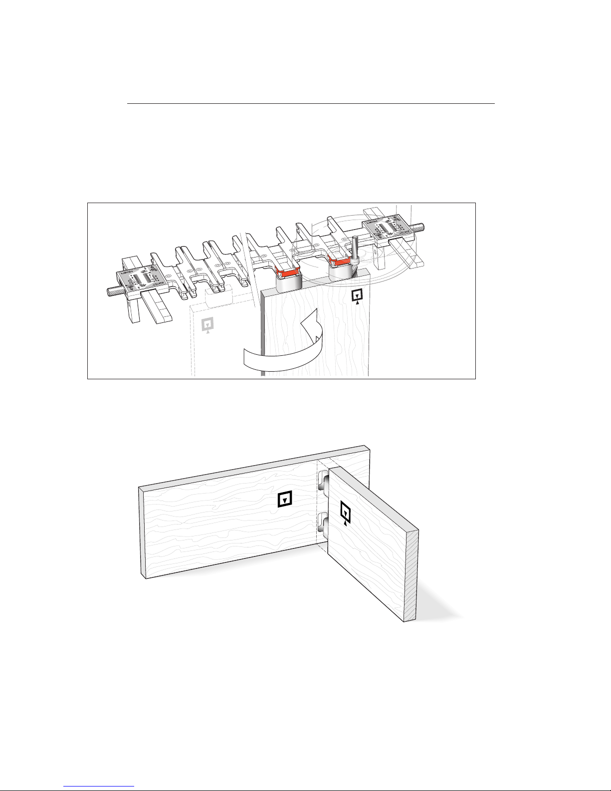
29
Tenon
Flip the tenon board side
for side to the other end
of the jig, like turning a
page of a book. Rout the
remaining corners of the
tenons.
ACTIVE GUIDE SURFACES
THE FINISHED JOINT
Page 36

B A S I C J I G F U N C T I O N S
Chapter 5 M2 U s er Gu i d e
30
Page 37
Wood Preparation
CHAPTER 6
Page 38

W O O D P R E PA R AT I O N
Chapter 6 M2 U s er Gu i d e
32
Page 39
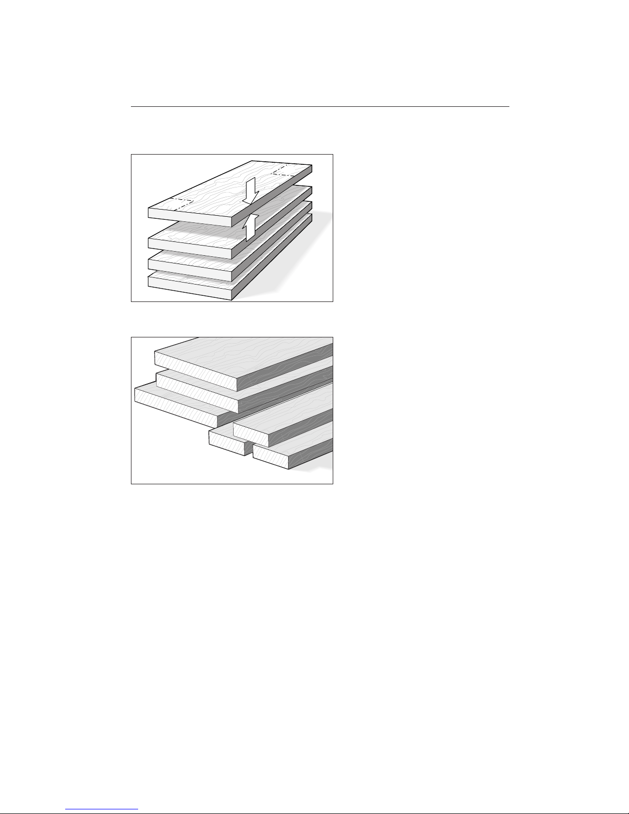
6-1
Stock for use on the Leigh M2 should generally be prepared straight, flat, of even thickness and equal widths, with square ends
and edges. The jig will work with boards
of many odd shapes, but make sure the jig
can function properly with the required
shape of board before you try to use it on
a project workpiece.
6-2
You will want to test the M2, so prepare
some lengths of 3⁄4" x 5 1⁄2" [20 x 140mm]
boards and some narrow pieces the exact
same thickness. Cut them to length as you
need them for the various jig tests you want
to perform. Use them for practice with the
jig’s various joint modes so you can see how
the different modes work. Remember,
though, that boards of different thicknesses can be joined just as easily.
90o
90o
33
Page 40

W O O D P R E PA R AT I O N
Chapter 6 M2 U s er Gu i d e
34
Page 41
The Multiple Mortise
and Tenon Joint
CHAPTER 7
Page 42
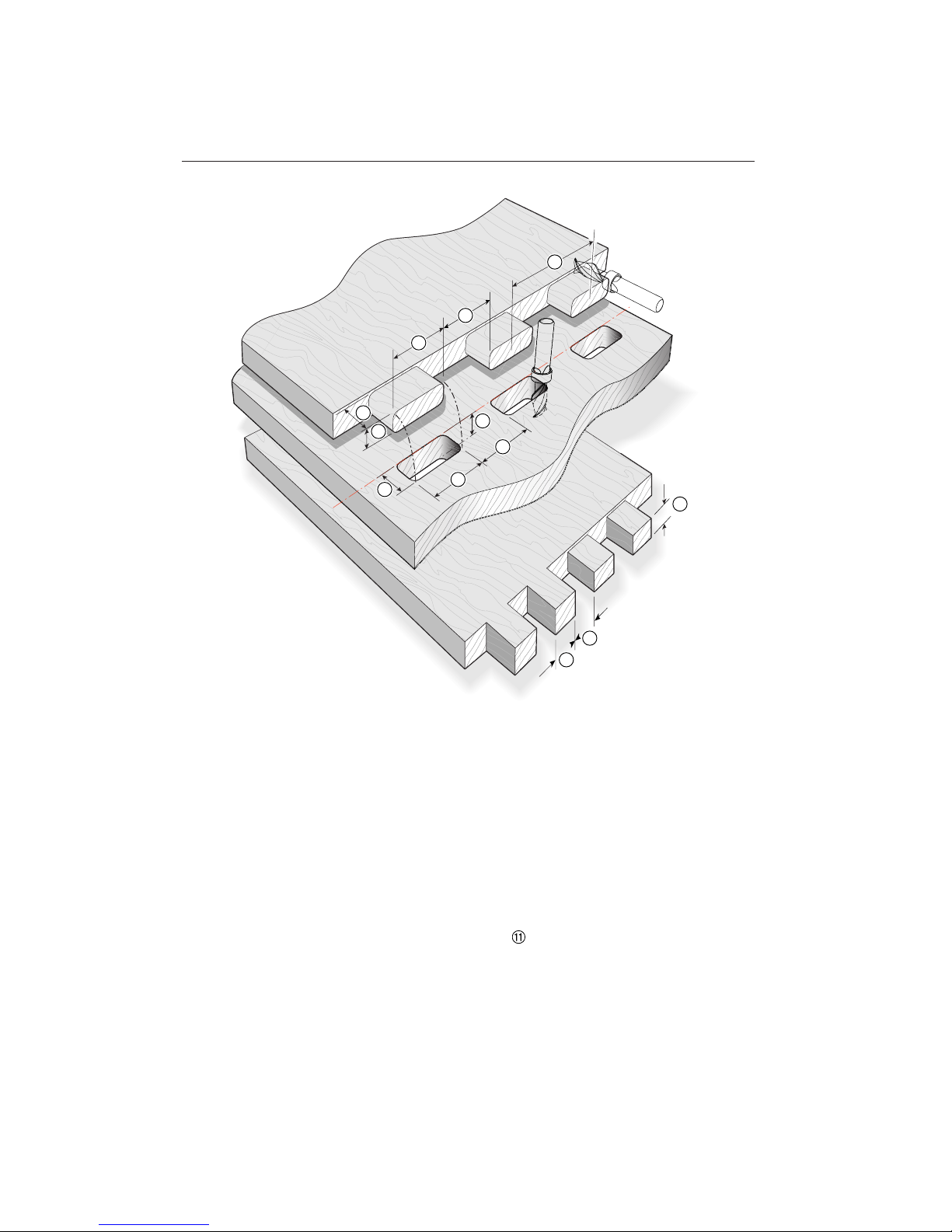
2
9
4
6
1
3
11
11
10
5
8
7
T H E M U LT I P L E M O RT I S E A N D T E N O N J O I N T
Chapter 7 M2 U s er Gu i d e
36
Mortise Width is controlled by the
distance between single guidefingers.
Mortise Height is controlled by the
distance between the finger rail and mortise fence.
Mortise Depth is controlled by the
depth of cut of the router cutter.
Mortise Spacing is controlled by the
distance between pairs of guidefingers.
Tenon Width is controlled by the dis-
tance between single guidefingers – the
same setting as for the mortises!
Tenon Height and
Square Tenon Height
are controlled by the finger scale setting.
Tenon Depth is controlled by the
depth of cut of the router cutter.
Tenon Spacing and
Finger Joint Spacing
are controlled by the distance between
pairs of guidefingers – the same setting
as for the mortises!
Joint Description
Note: Closest mortise and tenon centres : 11⁄4"[31,75 mm]
WIDTH
HEIGHT
DEPTH
SPACING
Page 43
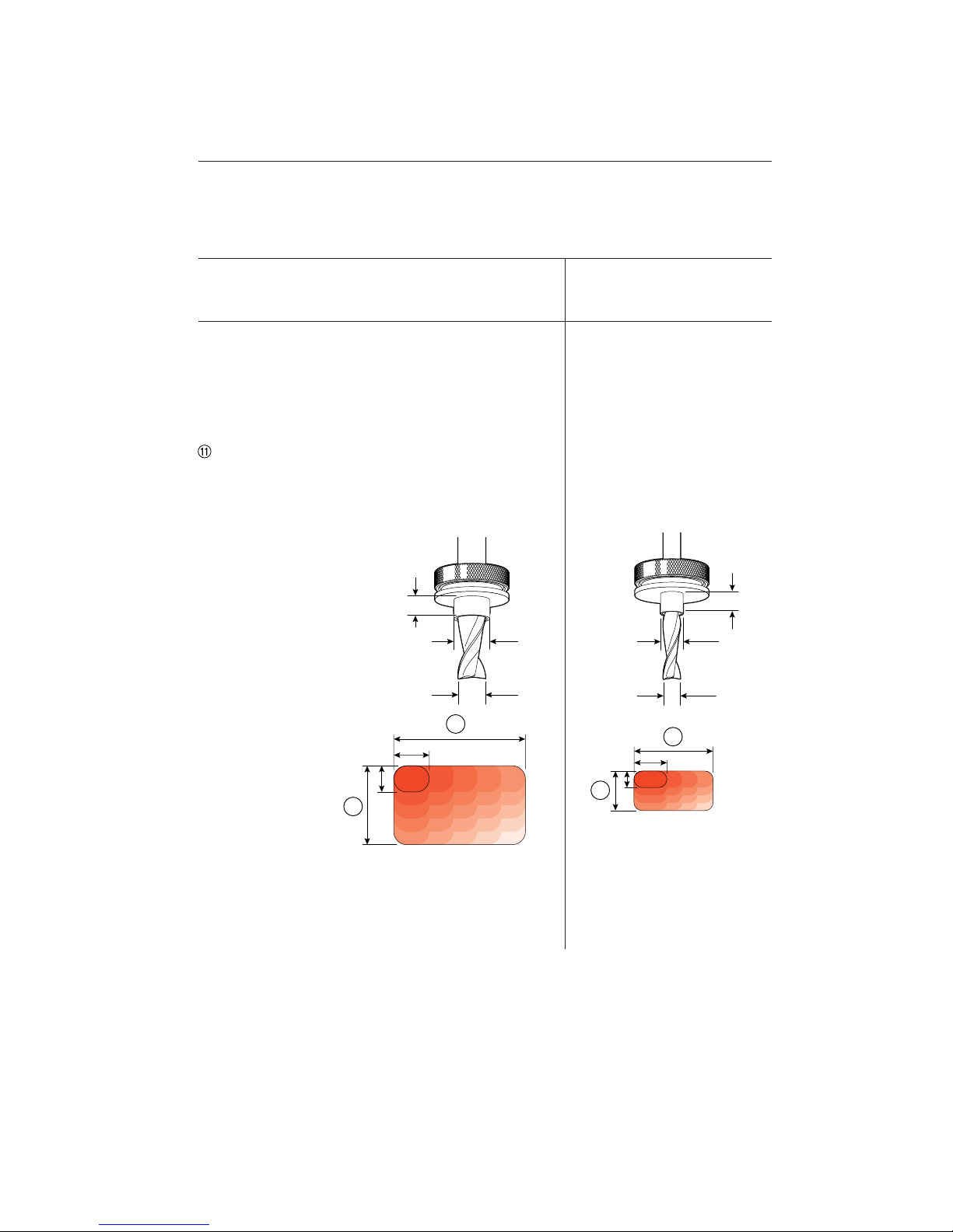
2
4
2
4
37
7
/16"[11,1mm]
1
/4"[5 - 6.5mm]
5
/16"[7,9mm]
1
/4"[5 - 6.5mm]
5
/8"[15,9mm]
1
/2"[12,7mm]
Option 1:
5
⁄8"[15,9mm] outside dia. Guidebush
and
1
⁄2"[12,7mm] Spiral Upcut Cutter*
Option 2:
7
⁄16"[11,1mm] outside dia Guidebush
and
5
⁄16"[7,9mm] Spiral Upcut Cutter
Joint Technical Specifications, Guidebush and Cutter Selection
Width of Joint
Tenon Board Thickness
Mortise Board Thickness
Tenon Height
Tenon Width
“Square” Tenon Height
Finger Joints
Closest Tenon Centres
Up to 24"[610mm]
1
⁄2"[13mm] to 11⁄2"[38mm]
Up to 11⁄2"[38mm]
1
⁄2"[12,7mm] to 11⁄2"[38mm]
5
⁄8"[15,9mm] to 21⁄4"[60mm]
1
⁄2"[12,7mm] to 13⁄8"[35mm]
5
⁄8"[15,9mm] width/up, variable
11⁄4"[31,75mm]
Up to 24"[610mm]
5
⁄16"[8mm] to 3⁄4"[20mm]
Up to 3⁄4"[20mm]
5
⁄16"[7,9mm] to 3⁄4"[20mm]
5
⁄8"[15,9mm] to 11⁄2"[40mm]
5
⁄16"[7,9mm] to 3⁄4"[20mm]
5
⁄8"[15,9mm] width/up, variable
11⁄4"[31,75mm]
Notes
* 1⁄2"[12,7mm] spiral upcut bit HSS, standard equipment.
Guidebushes must have a minimum 7⁄32"[5mm] to maximum 1⁄4"[6,5mm] projection from router
base.
Page 44

T H E M U LT I P L E M O RT I S E A N D T E N O N J O I N T
Chapter 7 M2 U s er Gu i d e
38
Page 45
Operations Procedures
for Mortises
CHAPTER 8
Page 46

IMPORTANT: Before using this attachment on a project, thoroughly familiarize
yourself with the following procedures and
adjustments. Use low cost 3⁄4"[20mm] solid
wood and practice until proficient.
Note: Procedures for 5⁄16"[7,9mm] cutter
and 7⁄16"[11,1mm] guidebush are identical, but see 8-21regarding change of
finger orientation.
O P E R AT I O N S P R O C E D U R E S F O R M O RT I S E S
Chapter 8 M2 U s er Gu i d e
40
Page 47
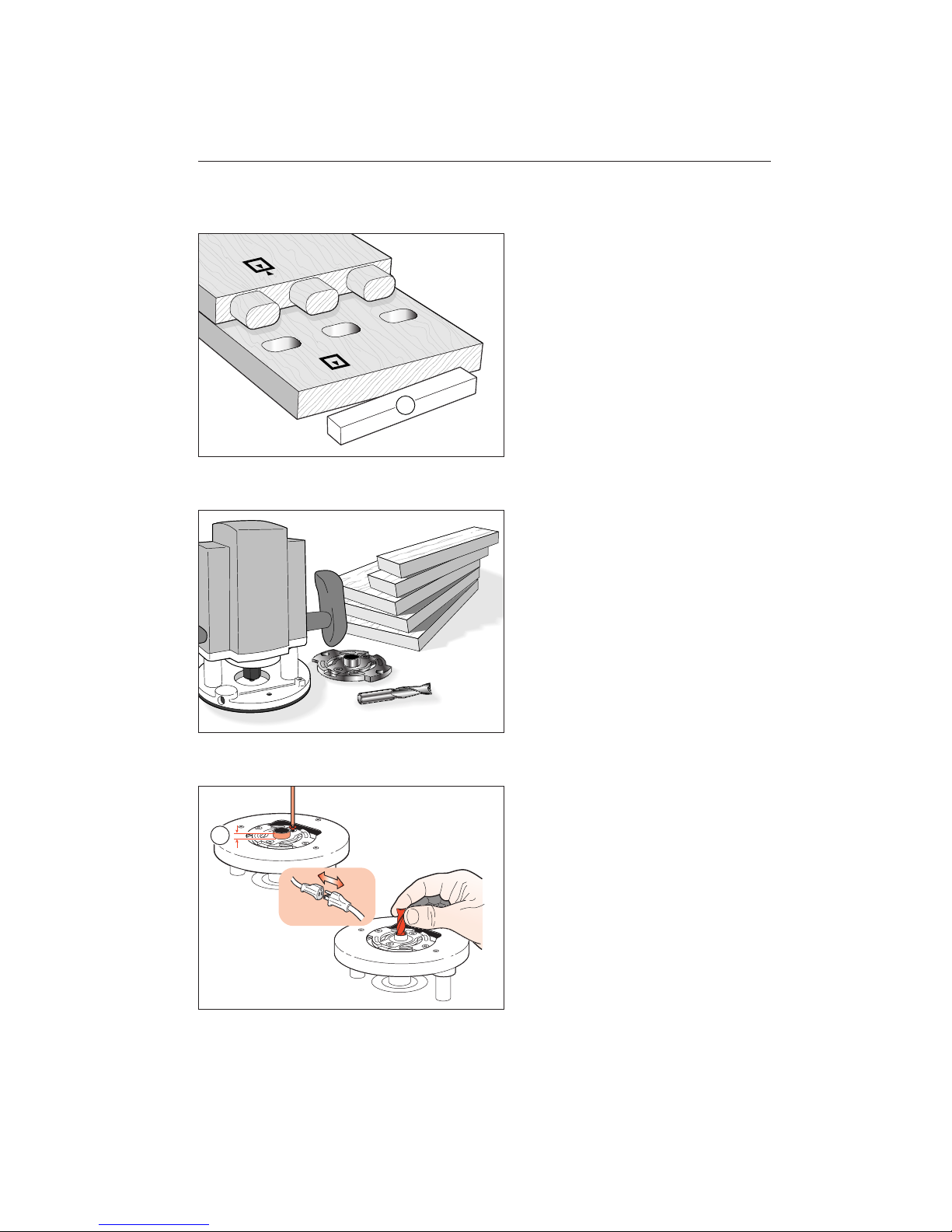
8-1
Let’s look at how to make a simple multiple mortise & tenon joint. Make a single
matching row of mortises and tenons without regard for symmetry or alignment.
Example: Using 1⁄2"[12,7mm] cutter and
5
⁄8"[15,9mm] guidebush combination and
5
⁄8"[15,9mm] high tenons in 3⁄4"[20mm]
stock.
For this procedure you will require the
“mortise block”-. See 1-7 for mortise
block description.
8-2
You will need some practise boards 3⁄4"-x-5
1
⁄2"-x12"[20x140x305mm]or so long, plus
two narrow boards exactly the same thick-
ness for single test tenons. For this trial use
a plunge router with 1⁄2"[12,7mm] collet,
5
⁄8"[15,9mm] guidebush, and 1⁄2"[12,7mm]
spiral upcut cutter (Leigh No.180).
8-3
Fit the 5⁄8"[15,9mm] guidebush securely to
the router. Guidebush projection from the
router base must be at least 7⁄32"[5mm] and
must not exceed 1⁄4"[6,5mm]-.
Fit the 1⁄2"[12,7mm] spiral upcut cutter
to the router.
1
41
Page 48
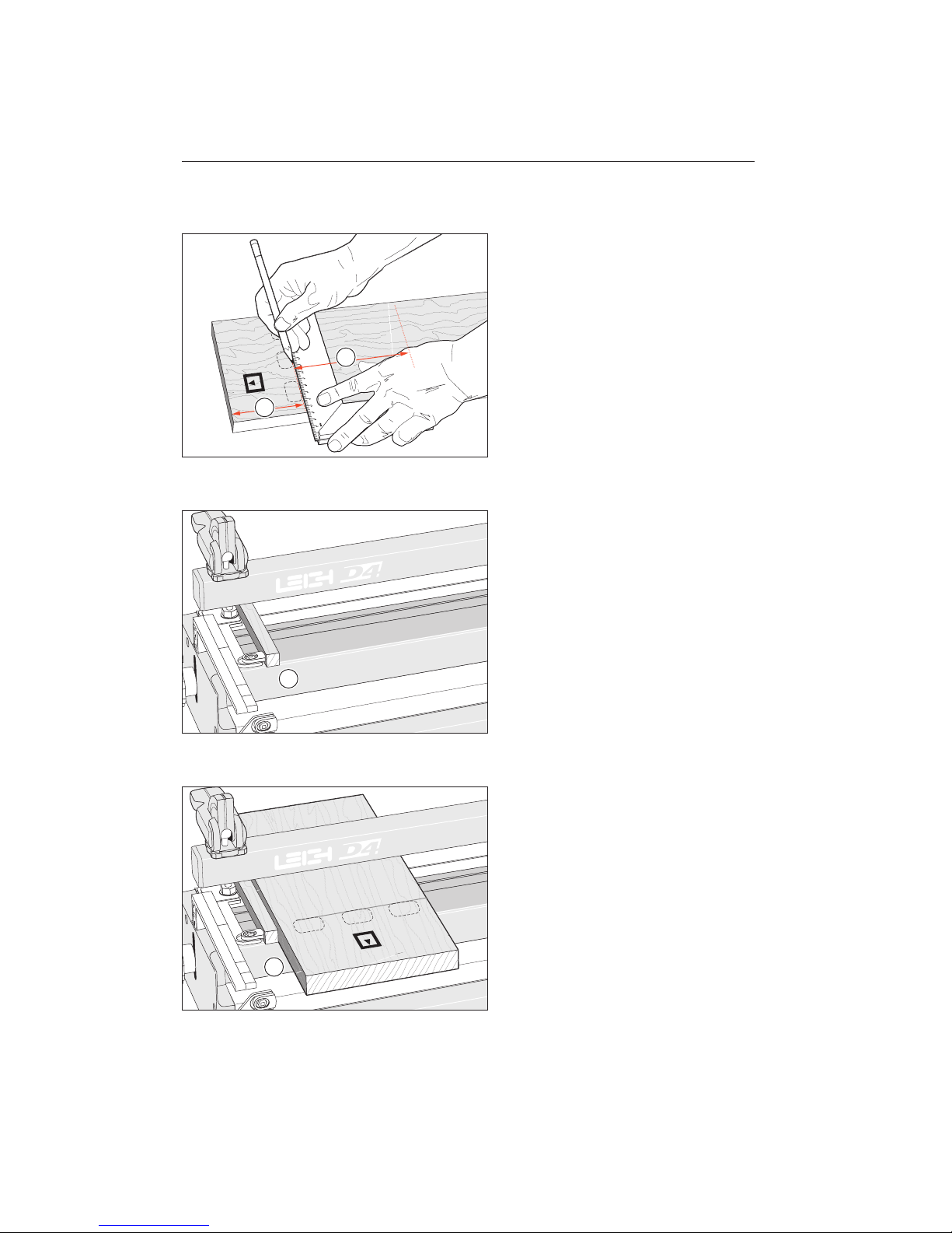
8-4 Joint Layout.
Mark out the position of the top edge of
the mortise row which will go towards
the rear of the jig (the mortise line), about
4"[100mm] from the board end . Mark
this line on the inside face .
It is not necessary to outline the mortises,
we have just illustrated them here for
clarity.
Note: the closest that a mortise line can be
to the clamping end of a board is between
51⁄2"[140mm] to 61⁄2"[165mm].
8-5
Place the mortise block against the top left
hand side stop. Keep it there for all mortising procedures.
8-6
Fit the mortise board horizontally under the
rear clamp bar, inside face up, against
the mortise block/side stop, and lightly
clamp. The board position is not critical
at this time.
1
2
1
1
O P E R AT I O N S P R O C E D U R E S F O R M O RT I S E S
Chapter 8 M2 U s er Gu i d e
42
Page 49
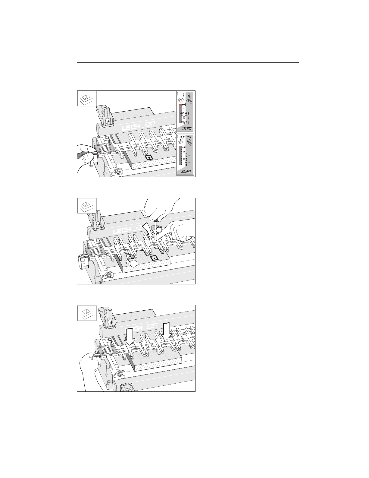
8-7
Place the finger assembly on the support
brackets in 1⁄2"[12,7mm] mortise mode
and exactly on the 1⁄2"[12,7mm] setting
indicated on the scale with a black triangle
pointer. The position is illustrated here in
red. Tighten thumb screws.
8-8
Lower finger assembly to within 1⁄16"[2mm]
of mortise board . Loosen and adjust fingers to the desired layout of mortises, and
retighten. Do not overtighten the finger
lock screws. The special screwdriver provided will give more torque than is necessary for adequate lock-up. Always apply
(hand) finger pressure to the guidefinger
above the large 3⁄4"[19mm] guide rail when
tightening up the finger screws.
8-9
Lower finger assembly flush onto the mortise board and tighten end bracket knobs.
Ignore mortise line for now!
1
43
Page 50
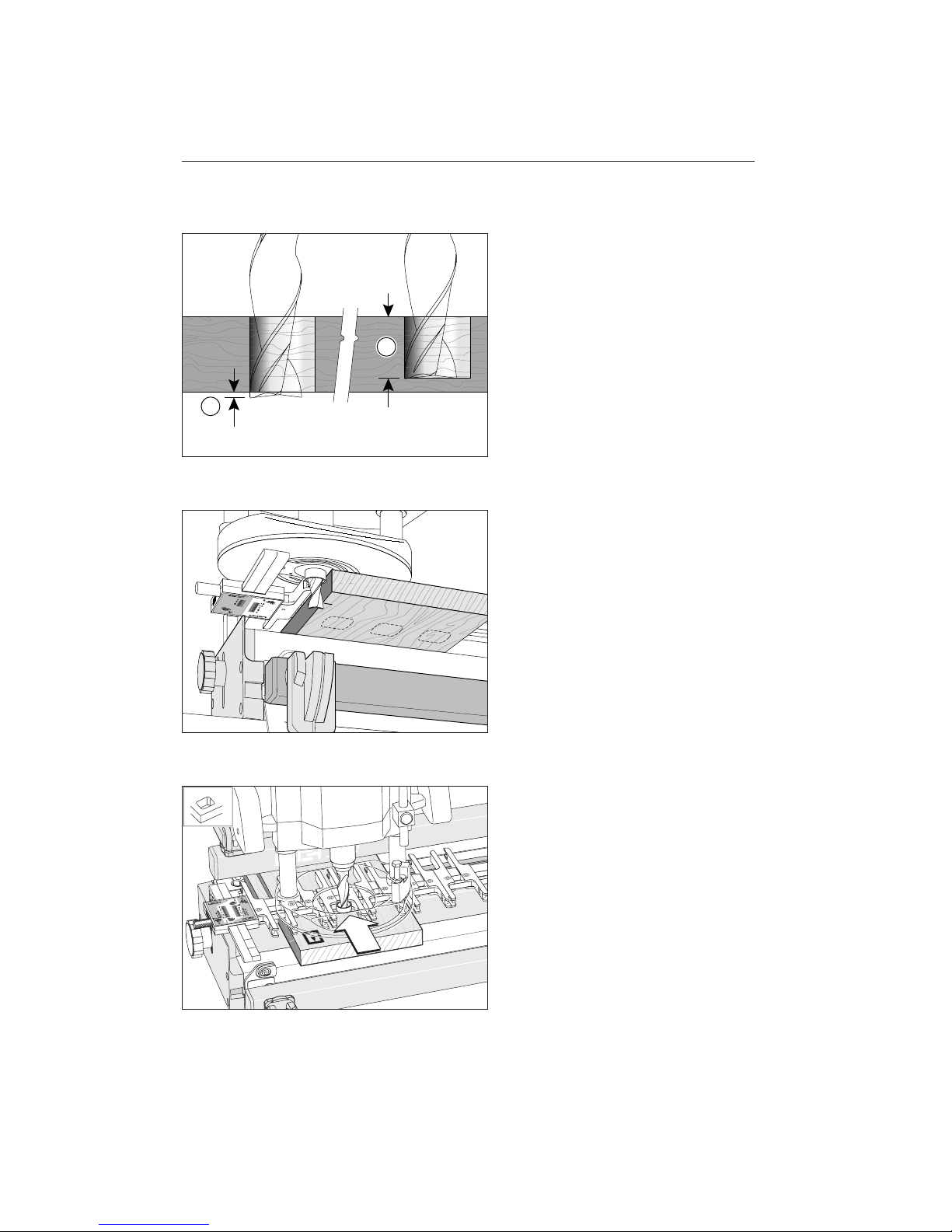
8-10
Always adjust and check for correct depth
of cut.
Through mortises should be cut with the
cutter clearly through the board .
Blind mortises should be cut to your desired
depth .
8-11
For these sample through mortises, adjust
the plunge router depth stop to allow for
a maximum cut depth of, say, 1⁄8"[3mm]
more than the mortise board thickness.
8-12
Position plunge router (unplugged) with
plunge raised on the finger assembly, guidebush touching the front finger rail.
1
2
O P E R AT I O N S P R O C E D U R E S F O R M O RT I S E S
Chapter 8 M2 U s er Gu i d e
44
Page 51
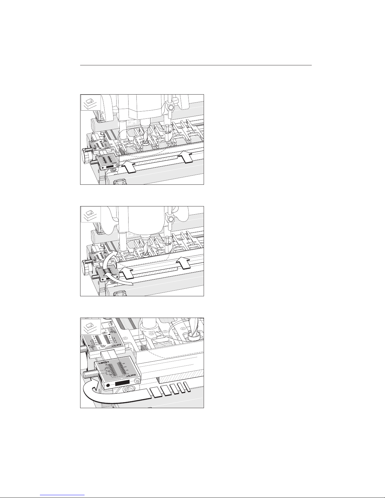
8-13
Place mortise fence on support brackets,
fence up, until the fence touches the router
base. With some small router bases, the
fence may touch the fingers before reaching the router base. If so, See Figs. 8-14
and 15 below, otherwise, go directly to
Figure 8-16.
8-14
With some smaller router bases it may be
necessary to turn the fence end for end,
replace on brackets and use back of fence
as a guide.
8-15
In some cases it may even be necessary to
reverse the scales end for end on the fence
to ensure the scale thumb screws are far
enough in to engage the support brackets.
45
Page 52
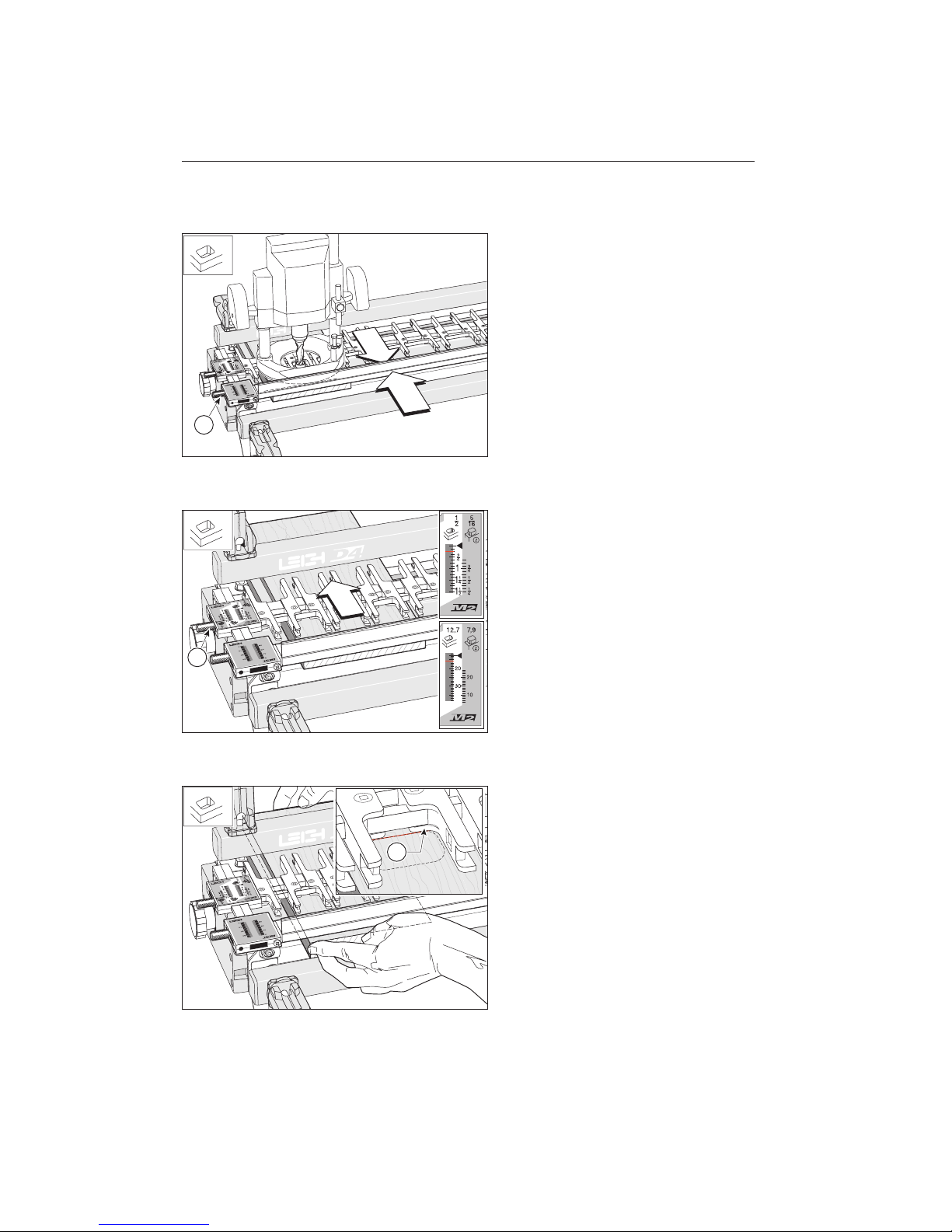
8-16
With light inward pressure on the fence,
equalize the fence scale reading at each end
of the jig on the most convenient pair of
support bracket lines and tighten the fence
scale thumb screws . This will parallel the
fence with the finger assembly. Check for
free left-right router movement at both
sides of the mortise board.
Remove router from jig.
8-17
At the 1⁄2"[12,7mm] setting, and the router
trapped between the finger rail and fence,
the router can only cut 1⁄2"[12,7mm] high
mortises, i.e. the cutter diameter. Move the
finger assembly toward the rear of the jig so
the scales read the required mortise height,
5
⁄8"[16mm] in this instance. Tighten the
thumb screws .
8-18
Loosen the rear clamp and align the first
mortise line just in front of the small projections on each guide finger , i.e. full
line thickness showing in front of projection, and the edge of the board against the
mortise block/side stop. Firmly clamp in
place.
1
1
1
O P E R AT I O N S P R O C E D U R E S F O R M O RT I S E S
Chapter 8 M2 U s er Gu i d e
46
Page 53
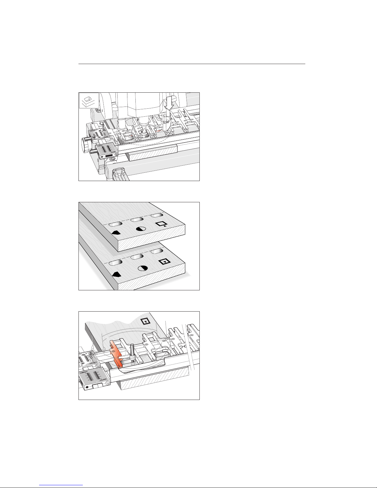
8-19
Rout out all mortise positions on this row
and on all similar rows. Plunge and rout
about one third of the board thickness at
a time.
8-20
If you are routing through mortises in
opposite cabinet sides, use the same reference edge (cabinet front or rear) against the
same side stop each time. One side of the
cabinet would be routed outside face up;
the other side, inside face up.
8-21
When routing with a 5⁄16"[7,9mm] cutter,
the outer finger (highlighted in red) is used
as a guidefinger.
47
Page 54

O P E R AT I O N S P R O C E D U R E S F O R M O RT I S E S
Chapter 8 M2 U s er Gu i d e
48
Page 55
Operations Procedures
For Tenons
CHAPTER 9
Page 56

O P E R AT I O N S P R O C E D U R E S F O R T E N O N S
Chapter 9 M2 U s er Gu i d e
50
Page 57
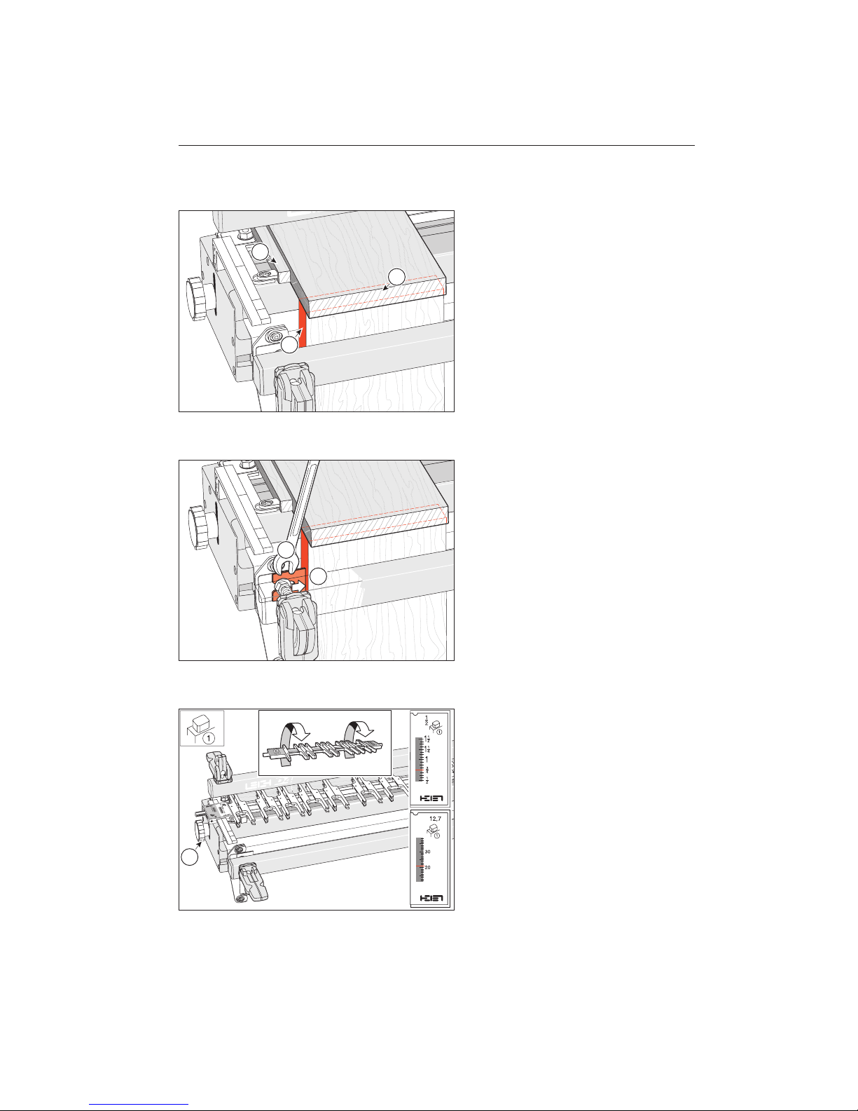
9-1
Remove the mortise fence and the finger
assembly. Clamp a straight sided board in
the rear clamp, touching against the mortise block/side stop , and the front edge
overhanging the jig front .
Place another straight sided board in the
front clamp and position it so that the top
left corner is perfectly flush with the side
edge of the horizontal board and clamp
it in place. Double check that the side edges
are flush at and leave both boards in
place.
9-2
Slightly loosen the left hand clamp bolt
nut- (this will not loosen the board)
and slide the side stop extension to touch
flush and square to the edge of the vertical
board-. Hold it in position and tighten
the nut.
Remove both boards.
9-3
Rotate the finger assembly toward you 180°
and replace it on the support brackets in the
1
⁄2"[12,7mm] tenon mode. The scale
setting is not important for now. Fit the jig
spacer board in the rear clamp, under the
finger assembly. Lower the fingers flush
onto the board and tighten the support
bracket knobs .
1
2
3
2
1
1
51
Page 58
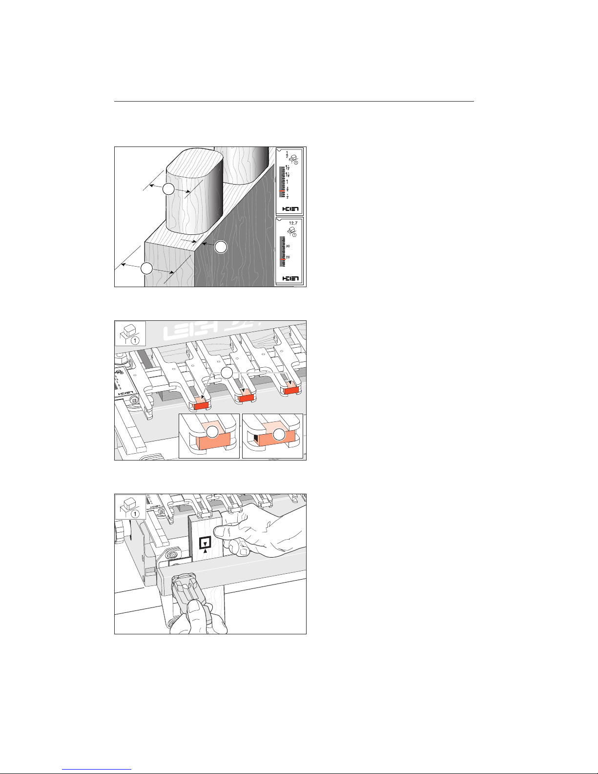
9-4
For a crisp appearance, shoulder the tenons
slightly . For corrected scale reading, use
this formula:
Tenon Board Thickness
+ Mortise Height
÷ 2 = Tenon Scale Setting
Example: (
3
⁄4"[20mm] + 5⁄8"[16mm]) ÷ 2 = 11⁄16"[18mm]
Set 1⁄2"[12,7mm] tenon scale on
11
⁄16"[18mm] or on your actual calculated
setting.
9-5
Fit tenon bridge pieces where there are
gaps between the tenon guides (just like
half-blind dovetail tails). To make bridge
pieces, use a strip of 1⁄4"[6,35mm] by
1
⁄2"[12,7mm] hardwood such as maple.
Fit short pieces in the slots on the inside
finger faces . Ensure a tight sliding fit on
the 1⁄4"[6,35mm] dimension only.
D4R owners may use the plastic bridge
material supplied with that jig.
9-6
Fit a narrow test piece, exactly the same
thickness as the workpiece, vertically in the
front clamp under a pair of tenon guides. It
does not have to be touching the side stop
extension for this “fit test”.
3
1
2
1
3
2
O P E R AT I O N S P R O C E D U R E S F O R T E N O N S
Chapter 9 M2 U s er Gu i d e
52
Page 59
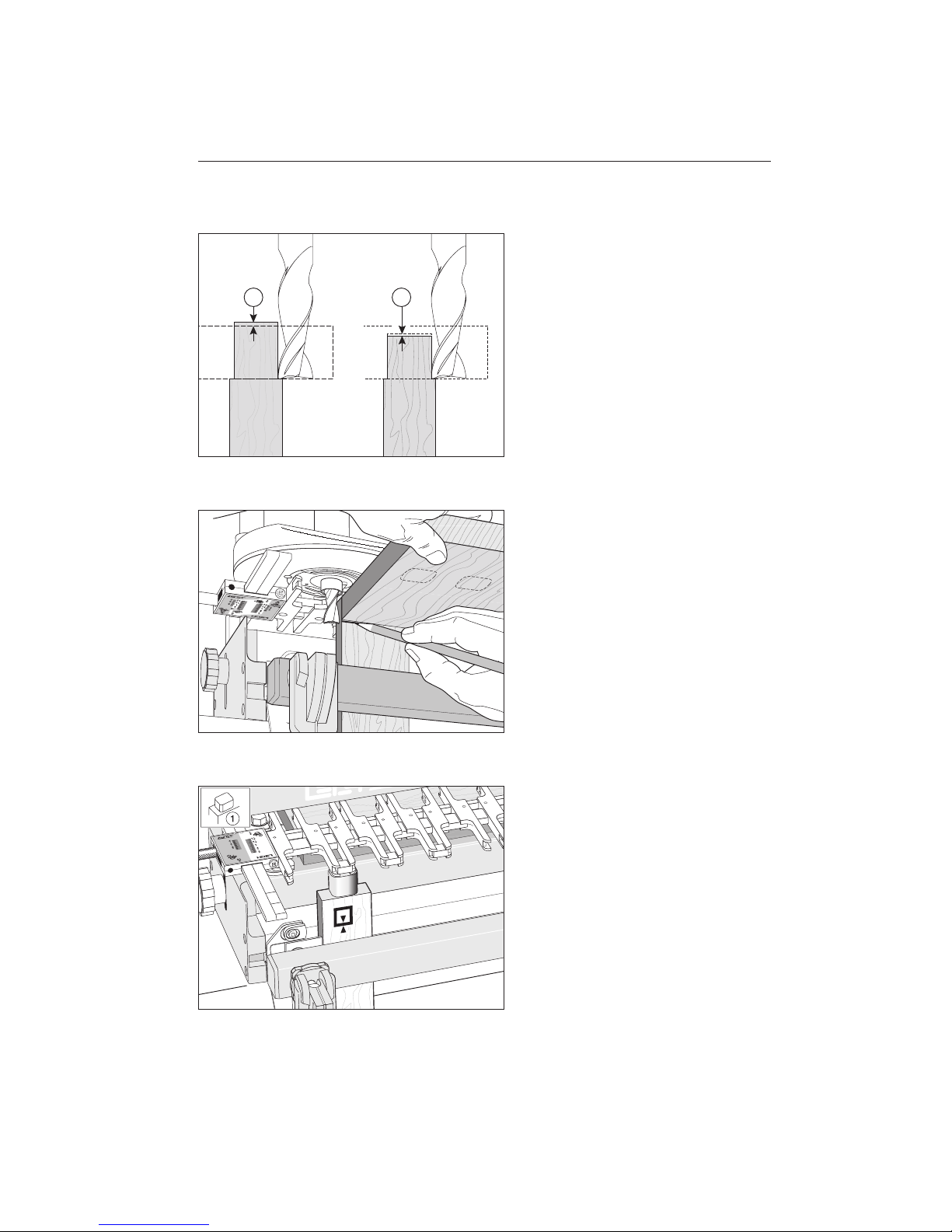
9-7
Always adjust and check for correct depth
of cut.
Through tenons should be cut to project
slightly through the mortises to allow for
cleanup .
Tenon depth for blind mortises should be
cut slightly less than than the mortises to
ensure clearance during assembly .
9-8
For through tenons, use the mortise board
to mark its thickness onto the test board.
Lower the cutter depth to suit.
9-9
Rout around the tenon guides and bridge
piece to cut the first part of the tenon.
1 2
53
Page 60
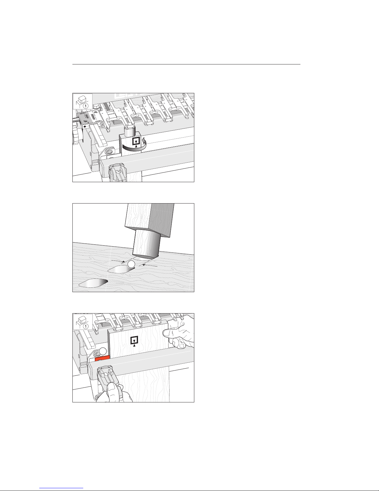
9-10
Remove the test piece and turn it 180°
under the same tenon guide and re-clamp.
Side to side alignment is not critical, you
are only testing tenon height.
Rout the other half of the test tenon.
9-11
Try the test tenon in a mortise to test tenon
height . If tenon height is loose, move the
finger assembly out (towards the operator)
by half the difference, e.g., if the tenon
height is 1⁄32"[1mm] loose, move the finger
assembly out by 1⁄64"[0,5mm]. If too tight,
move the finger assembly in (away from
operator) by half the difference. Cut other
test tenons as required to achieve the desired
fit. Record the 1⁄2"[12,7mm] tenon scale
setting and leave it in position.
9-12
Fit the tenon workpiece in the front
clamp at the left hand end, it can be
either face in or out . It should lightly
touch the underside of the guide fingers
and the left hand side stop extension-.
1
1
O P E R AT I O N S P R O C E D U R E S F O R T E N O N S
Chapter 9 M2 U s er Gu i d e
54
Page 61
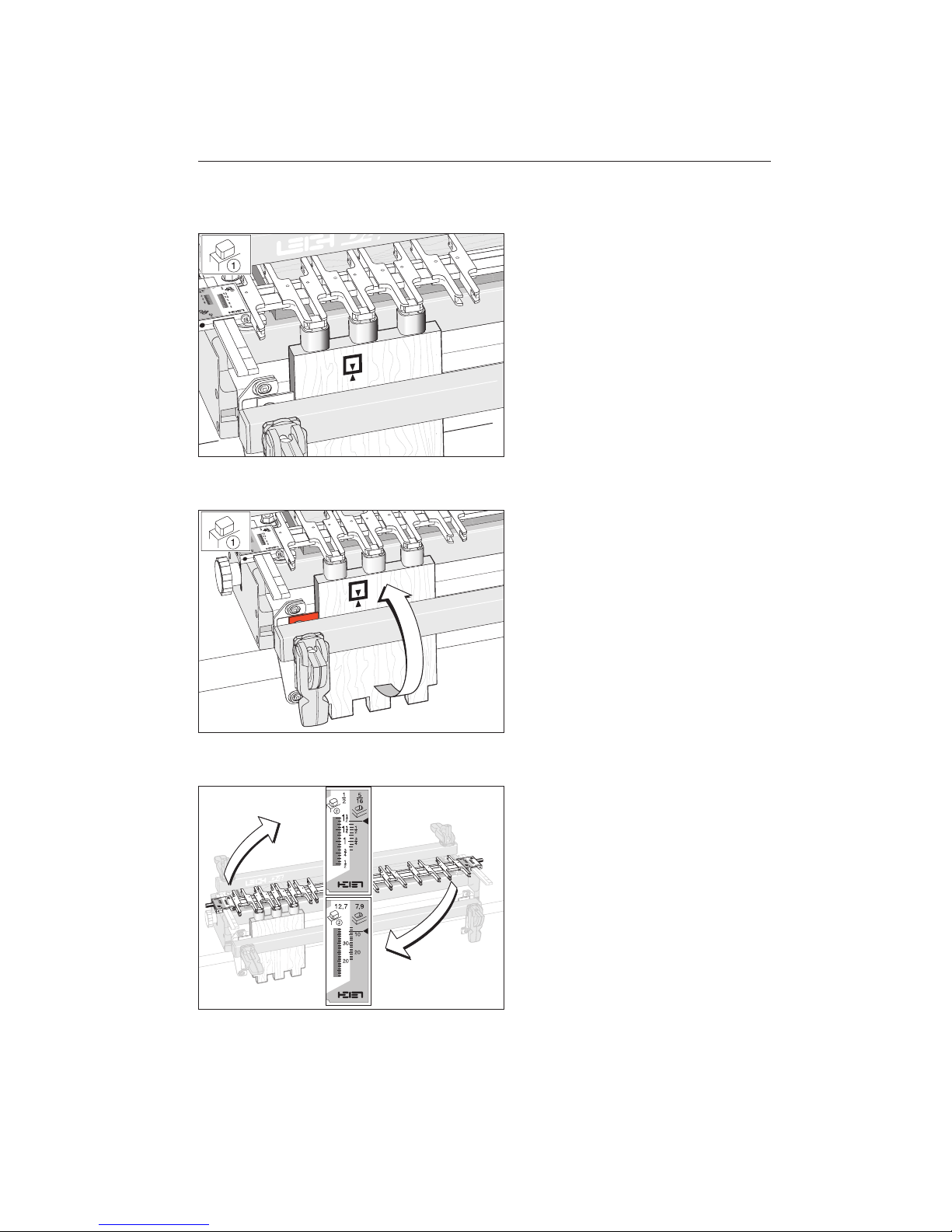
9-13
Rout the first half of the tenons.
9-14
Flip the board end for end, keeping the
same board edge to the side stop extension. Rout the first half of tenons at the
opposite end of the board under the same
guide fingers. Repeat with all similar tenon
boards.
IMPORTANT: Rout an extra scrap tenon
board of the same thickness but not necessarily the same length or width.
9-15
Make sure you noted the scale setting.
Remove the finger assembly and flip it
end for end to the 1⁄2"[12,7mm] tenon
mode. Set it on exactly the same recorded
position as for the 1⁄2"[12,7mm]
tenon
mode.
55
Page 62
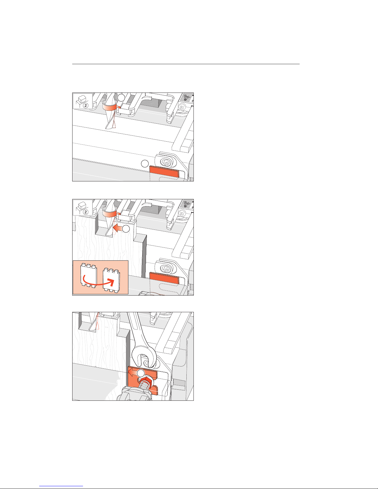
9-16
You now need to set the right hand side
stop extension-. First, place the router
(unplugged) onto the finger assembly, with
the cutter plunged and the guidebush contacting the side of a guidefinger-.
9-17
Remove the scrap tenon board. Turn it to
the right hand end of the jig, like turning
the page of a book, and position it under
the guides with a tenon lightly touching the
cutter-. Making sure that the guidebush
maintains contact with the finger and the
tenon with the cutter; clamp the workpiece.
9-18
Now loosen the right hand clamp bolt
nut and slide the side stop extension out
to touch flush and square to the edge of
the tenon board-. Hold it in position
and tighten the nut.
1
2
O P E R AT I O N S P R O C E D U R E S F O R T E N O N S
Chapter 9 M2 U s er Gu i d e
56
Page 63
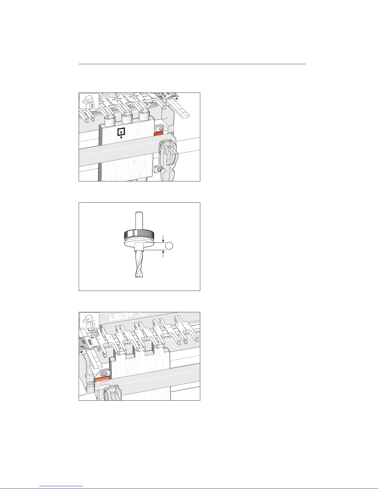
9-19
Rout one end of the scrap tenon board
and test for accuracy. Repeat the sidestop
extension adjustment if necessary.
Finish routing the scrap tenons and
test for fit. If necessary, make final
adjustments for tenon height before
routing the second half of all tenons.
9-20
Procedures are identical for 5⁄16"[7,9mm]
cutter and scales in the 5⁄16"[7,9mm]
modes.
Make sure to check the length of the
7
⁄16"OD guidebush-. This should not
exceed 1⁄4"[6,5mm].
9-21 Square Cornered Tenons
Note: Because square tenons are all routed
at one end of the jig, sidestop extensions are
not required.
If square tenons are required, always use
the 1⁄2"[12,7mm]
tenon mode. Simply
move the finger assembly out to the highest
tenon setting to ensure straight-sided
tenons. The mortise height will either have
to be the same as the tenon board thickness, or...
1
57
Page 64
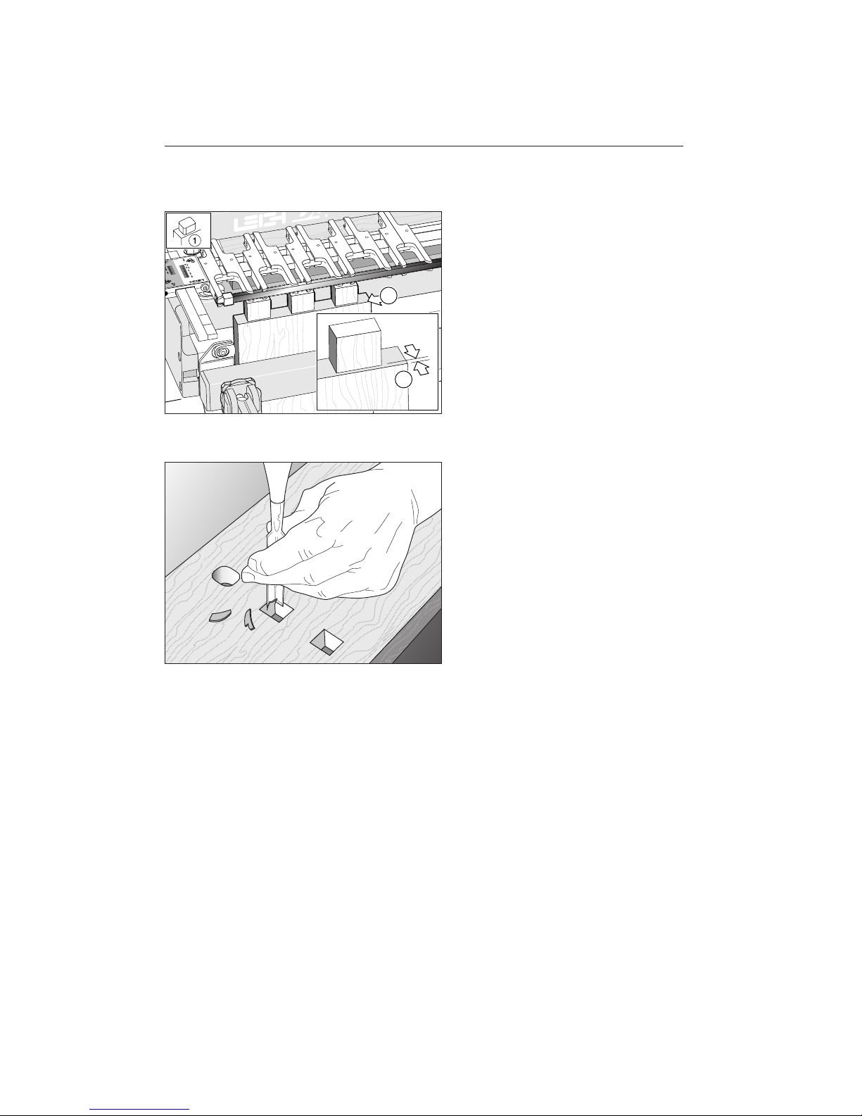
9-22
...remove the bridge pieces and use the
dovetail jigs cross cut bar to shoulder the
square tenons-.
9-23
Mortises for square tenons will have to be
chopped square in the corners – a simple
matter with a good corner chisel.
1
1
O P E R AT I O N S P R O C E D U R E S F O R T E N O N S
Chapter 9 M2 U s er Gu i d e
58
Page 65
Beyond the Basics
with the Leigh M2
CHAPTER 10
Page 66

Chapter Foreword
Here are some unique (and inexpensive)
“joinery extras” your M2 will help you rout.
No other jig in the world can produce these
variably spaced box joints and “jumbo”
half-blind dovetails.
B E Y O N D T H E B A S I C S
Chapter 1 0 M2 U ser Gu i d e
60
Page 67
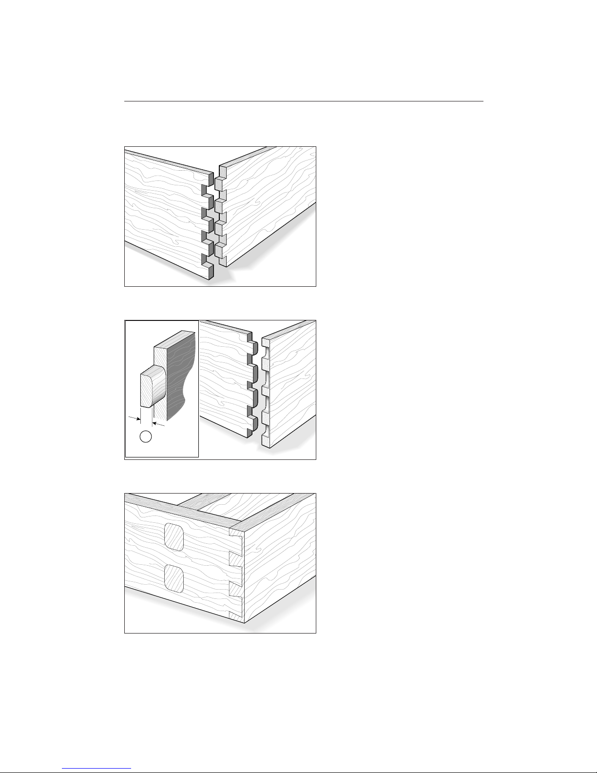
10-1 Finger Joints
Both sized cutter/guidebush combinations
will produce 5⁄8"[15,9mm] or larger finger/
box joints, either evenly or unevenly spaced.
Cut square tenons vertically under both
mortise and
tenon guides and presto!
Make corner joints, end-on-end joints,
hinges etc. The unique Leigh adjustable
guide fingers provide the joint edge finish
you want on any workpieces.
10-2 Half-Blind Variable Finger Joints
Cut the sockets horizontally in the mortise mode and the fingers vertically in the
tenon mode with the same depth of cut,
rounding only the first half of the tenons.
There are no specific scale settings for horizontal socket depth/pin thickness , but
a little trial and error testing will soon get
you there.
10-3 Jumbo Half-Blind Dovetails
It’s also easy to make Jumbo half-blind
dovetails utilizing the two largest dovetail
cutters from the D4, the No.90 and 100,
and two special diameter guide bushings.
Use the No.90 with the 717TP guidebush
to cut 1"[25mm] half-blind dovetails. The
No.100 used with the 720TP guidebush
will make 11⁄4"[31,7mm] deep half-blind
dovetails.
Instructions for this massive joint can be
downloaded from our website:
www.leighjigs.com.
1
61
Page 68

B E Y O N D T H E B A S I C S
Chapter 1 0 M2 U ser Gu i d e
62
Page 69
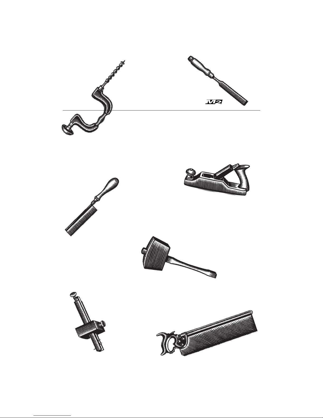
Guidebush and Cutter Selection
APPENDIX I
Page 70
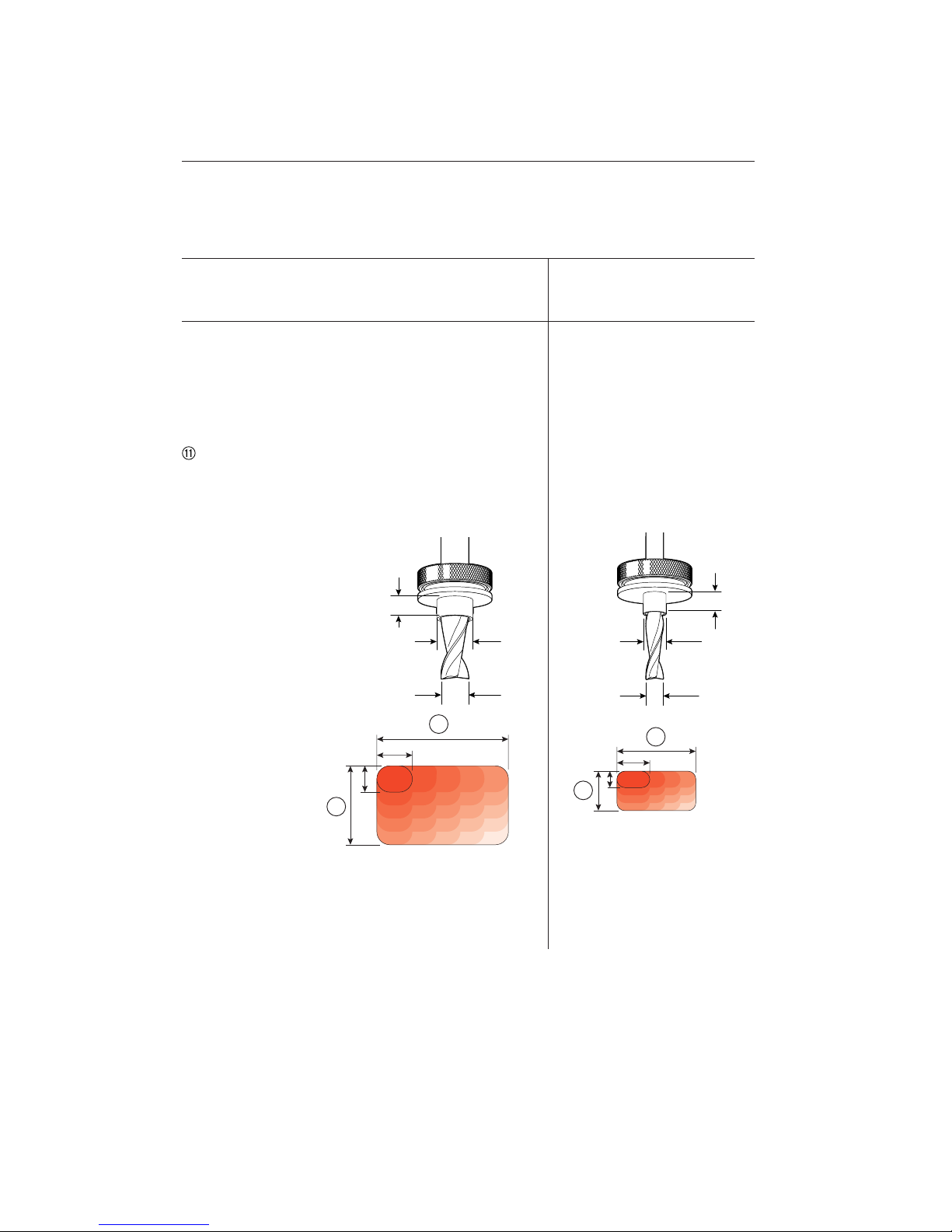
G U I D E B U S H A N D C U T T E R S E L E C T I O N
Appen d i x I M2 User G u i d e
64
2
4
2
4
7
/16"[11,1mm]
1
/4"[5 - 6.5mm]
5
/16"[7,9mm]
1
/4"[5 - 6.5mm]
5
/8"[15,9mm]
1
/2"[12,7mm]
Option 1:
5
⁄8"[15,9mm] outside dia. Guidebush
&
1
⁄2"[12,7mm] Spiral Upcut Cutter*
Option 2:
7
⁄16"[11,1mm] outside dia Guidebush
&
5
⁄16"[7,9mm] Spiral Upcut Cutter
Joint Technical Specifications, Guidebush and Cutter Selection
Width of Joint
Tenon Board Thickness
Mortise Board Thickness
Tenon Height
Tenon Width
“Square” Tenon Height
Finger Joints
Closest Tenon Centres
Up to 24"[610mm]
1
⁄2"[13mm] to 11⁄2"[38mm]
Up to 11⁄2"[38mm]
1
⁄2"[12,7mm] to 11⁄2"[38mm]
5
⁄8"[15,9mm] to 21⁄4"[60mm]
1
⁄2"[12,7mm] to 13⁄8"[35mm]
5
⁄8"[15,9mm] width/up, variable
11⁄4"[31,75mm]
Up to 24"[610mm]
5
⁄16"[8mm] to 3⁄4"[20mm]
Up to 3⁄4"[20mm]
5
⁄16"[7,9mm] to 3⁄4"[20mm]
5
⁄8"[15,9mm] to 11⁄2"[40mm]
5
⁄16"[7,9mm] to 3⁄4"[20mm]
5
⁄8"[15,9mm] width/up, variable
11⁄4"[31,75mm]
Notes
* 1⁄2"[12,7mm] spiral upcut bit HSS, standard equipment.
Guidebushes must have a minimum 7⁄32"[5mm] to maximum 1⁄4"[6,5mm] projection from router
base.
Page 71
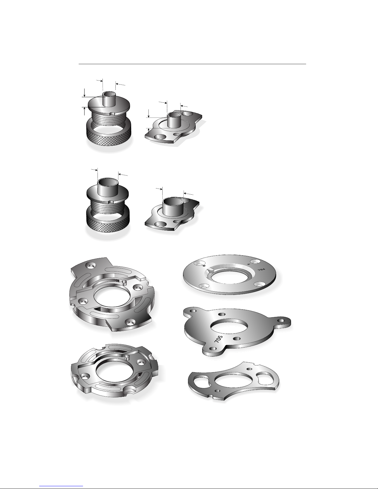
Guidebush Selection
Only two sizes of guidebush are used with
the Leigh M2. 7⁄16"[11,1mm] O.D. (outside
diameter) and 5⁄8"[15,9mm] O.D.
Us e 7⁄16"[11,1m m] gu i d ebush wi t h
5
⁄16"[7,9mm] cutter.
Us e 5⁄ 8 "[15,9mm] guidebus h w i t h
1
⁄2"[12.7mm] cutter.
Here are the two types of Leigh guidebush
and five Leigh adaptors. Use the chart on
page 67 to select the adaptor and/or guidebush required for your router.
65
5
/
8
"[15,9mm]
7
/
16
"[11,1mm]
1/4"[6,35]
5
/
8
"[15,9mm]
7
/
16
"[11,1mm]
1/4"[6,35]
706
CANADA
Adaptor No. 704
Adaptor No. 703
Adaptor No. 706
Adaptor No. 705
711 TP
711
716 TP
716
Adaptor No. 702
Page 72
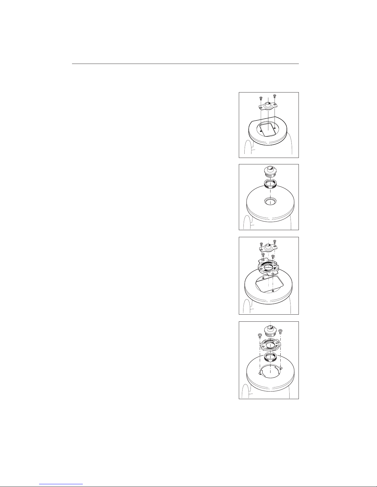
Leigh 711 and 716 guidebushes fit directly
to some routers using the screws that come
with the router.
Leigh 711TP and 716TP (TP stands for
Two Part) fit directly to Porter Cable and
most Black & Decker routers.
Leigh universal adaptors fit to a wide range
of plunge routers and accept one or both
types of Leigh bush.
G U I D E B U S H A N D C U T T E R S E L E C T I O N
Appen d i x I M2 User G u i d e
66
Page 73
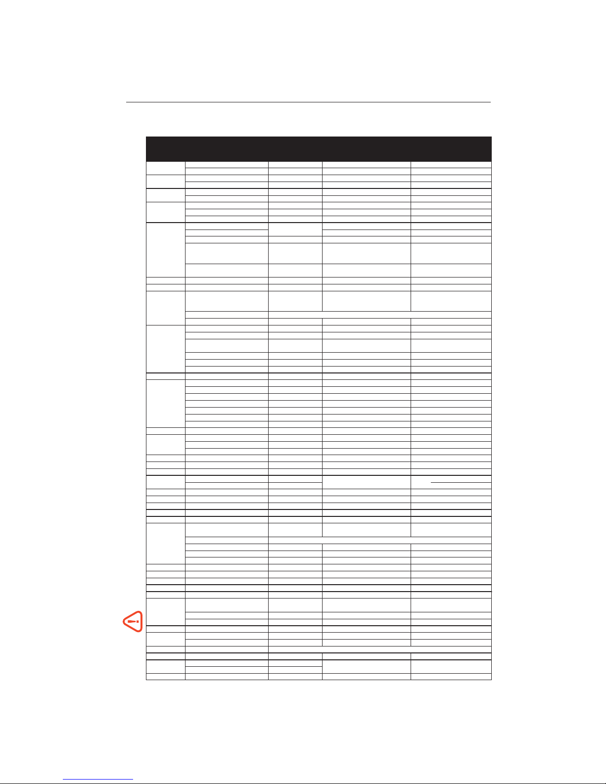
Note: Ideal barrel depth is 1/4" to 9/32" (6mm to 7mm) below the router base. Other manufacturers’ guidebushes may require careful cutting to length.
uGuidebush mounting screws are provided with adaptor and adaptor mounting screws are provided with router.
t5/8"[15,9mm] O.D. guidebushes are used only with 1/2"[12,7mm] shank router bits. n MAFELL – Rework the adaptor slightly. 9 SCHEER – Rework the router base slightly.
ROUTER ROUTER LEIGH OR ROUTER 7/16" [11,1mm] METHOD OF
MAKER MODEL MAKER’S ADAPTOR NO. OUTSIDE DIA. ATTACHMENT
GUIDEBUSH NO.
AEG OFE 710 in plunge base No adaptor required 711 Screws incl. w/router
OFSE 2000
703 711 u
ATLAS COPCO OFE 710 in plunge base, OFE 1000 No adaptor required
711 Screws incl. w/router
OFSE 2000
703 711 u
AXMINSTER AW635R No adaptor required
711 Screws incl. w/router
WHITE AW127R Adapter supplied w/router
711 Screws incl. w/router
All Professional, HD 1250, RP400K No adaptor required
711TP Threaded nut included
BLACK & DECKER 6200 720673-00 711TP 2 screws req’d. 249412-20
SR100, 7AEE, KW780 series No adaptor required
711 Screws incl. w/router
90140, 90098, 90088 82855 Screws included
90085, 90150, 90300, 90303, 90305, 91264 No adaptor required 82859 Screws included
1600, 1601, 1602, 1603, 1604, 1606, B1350 2 610 906 290
711TP Threaded nut included
BOSCH 1613,1613EVS,1613AEVS, 1614, 1614EVS, No adaptor required
1617, 1617EVS, 1618EVS, 1619EVS, B1450, (RA1100 required RA1107 No screws required
POF800ACE, GOF900ACE,GOF1300ACE, GOF2000CE
for VGS)
1611, 1611 EVS,1615,1615 EVS, B1550
702 711 u
GOF1600, GOF1700ACE
CASALS FT750, FT 1000E, FT2000E
703 711 u
CMT 1E
702R 711 u
Set of 3 bushes from Sears USA order no.25082
CRAFTSMAN All non-plunge models No adaptor required (stamped steel) or 25090 (plastic). Set of 3 Screws incl. w/set
(SEARS) bushes from Sears Canada order no.092-970-704
135275070 Plunge See Skill 1823 or 1835
Other plunge models
702 711 u
DW610 No adaptor required
711TP Threaded nut included
DW613 No adaptor required 711 Screws incl. w/router
DW614, DW615, DW621 North America Only
DEWALT DW624, DW625 and DW626 Adaptor supplied w/router
711TP Threaded nut included
DW621K and DW626 outside N. America 706 711 u
DW625 Type 1, 2 & 3 outside N. America
702 711 u
DW625 Type 4 outside N. America, DW625EK
702R 711 u
EINHELL EOF 850 SP, 0F-G 1100E No adaptor required
711 Screws incl. w/router
OF15, OF15E, OF97, OF97E
706 711 u
MOF68, MOF69, MOF96, MOF96E No adaptor required
711 Screws incl. w/router
ELU MOF131, MOF177 Type 1, 2 & 3
702 711 u
MOF177 Type 4, MOF177EK
702R 711 u
2720, 2721, 3328 No adaptor required
711TP Threaded nut included
3303, 3304 E09600 or 761 270-00 711TP Threaded nut included
3337, 3338, 3339 702 711 u
FEIN RT1800 Adapter supplied w/router
711TP u
FESTOOL OF1E, OF2E, OF650, OF900E, OF1000, OF1010E
704 711TP Threaded nut included
OF2000, OF2000E 705 711 u
OF1400 with Festool Adaptor
711TP Threaded nut included
FLEX All No adaptor required 711TP Threaded nut included
FREUD FT2000 703 711 u
HITACHI TR8, TR12, FM8, M8, M12 Series
703 711 u
HOLZ-HER 2355, 2356 No adaptor required
711
Screws incl. w/router
2365
702 u
ISKRA MR808A Series No adaptor required
711 Screws incl. w/router
JEPSON 7412
703 711 u
KANGO OF808 No adaptor required
711 Screws incl. w/router
KRESS OF690 IE Series No adaptor required
711 Screws incl. w/router
MAFELL LO65E
702 n 711 u
3600,3606,3608,3612, 3612B, 3612BR
703 711 u
MAKIT
A 3612C N. America,3620, 3621
3612C Europe Qk.Fit Base
Contact your National Leigh distributor
3601B 321 493-1 711TP Threaded nut included
RP0910, RP1110C 706 711 u
RF1100, RF1101, RD1100, RD1101, RP1101 No adaptor required
711TP Threaded nut included
METABO OF1612, OFE1812 704 711TP Threaded nut included
MILWAUKEE All No adaptor required 49-54-0520 Screws included
PERLES OF808 Series, OFE 6990 No adaptor required
711 Screws incl. w/router
PORTERCABLE(Rockwell) All No adaptor required
711TP Threaded nut included
POWER DEVIL All No adaptor required 711 Screws incl. w/router
R30, R50, R150, R151, RE155, R161
703 711 u
R500, R501, R502
RYOBI
R600, R601, RE600, RE601
702 711 u
R160, R165, R170, R175, RE175, R180, R185
706 711 u
SCHEER HM9, HM14, HM14-12, HM18, HM18-E No adaptor required 9
711 Screws incl. w/router
SKIL 1823 or 1835 91803
711TP Threaded nut included
All others No adaptor required 11592 Nut 11587
STANLEY All See Bosch Distributor
STAYER PR50 Series No adaptor required
711 Screws incl. w/router
TREND (FELLISATI) T5 No adaptor required
711 Screws incl. w/router
T9 Adaptor supplied w/router
WEGOMA OF850 Series No adaptor required
711 Screws incl. w/router
Check the make and model of your router in the left hand column. Where possible always order the Leigh adaptors
and guidebushes (in red)
which are specially designed for use on Leigh jigs. Other adaptors or guidebushes must be
purchased from the manufacturer’s own distributor.
67
Page 74

G U I D E B U S H A N D C U T T E R S E L E C T I O N
Appen d i x I M2 User G u i d e
68
Page 75
Parts List
APPENDIX II
Page 76

P A R T S L I S T
Appen d i x II M2 User G u i de
70
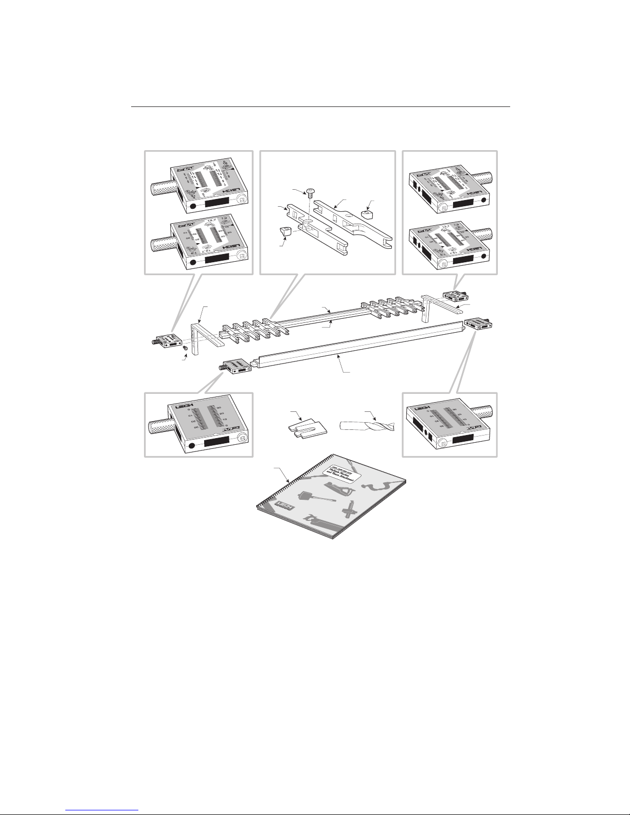
PART NO. QUANTITY DESCRIPTION
31 1 M2 User’s Guide
180 1
1
⁄2" [12,7mm] Spiral Upcut Bit, HSS
441 1 Guide Rail
451 1 Finger Guide Rail
480 10 Right Hand Finger Bevel Nut
490 10 Left Hand Finger Bevel Nut
500 20 Finger Lock Screws
600 10 Right Hand Finger c/w Bevel Nut and Screw
610 10 Left Hand Finger c/w Bevel Nut and Screw
620 1 Right Hand Support Bracket
630 1 Left Hand Support Bracket
641M 1 Millimetre Right Hand Finger Scale Assembly, complete
641 1 Inch Right Hand Finger Scale Assembly, complete
651M 1 Millimetre Left Hand Finger Scale Assembly, complete
651 1 Inch Left Hand Finger Scale Assembly, complete
660 4 Scale Lock Screws
671 1 Right Hand Fence Scale, complete
681 1 Left Hand Fence Scale,complete
690 1 Fence Assembly c/w Alloy Plugs
695 2 Side Stop Extensions
NOTE: When ordering parts, please quote the product model, serial
number (on underside of fence scales), part number, part description
and quantity required.
Page 77
71
31
180695
620
630
660
681
690
441
451
500
600
480
610
490
671
651
651 M
641
641M
Page 78

P A R T S L I S T
Appen d i x II M2 User G u i de
72
Page 79
Customer Support
APPENDIX III
Page 80

C U S T O M E R S U P P O R T
Appen d i x III M2 User G u ide
74
Joi ning Tr adi tion w ith Today
© 1990 Leigh Industries Ltd. All rights reserved.
No part of this pu blication may be reproduced,
stored in a retrieval system, or transmitted in any
form o r by any means, electronic , mechanica l,
recording, or otherwise, without the prior written
permission of Leigh Industries Ltd. 9/07
Australia & New Zealand
Carba-Tec Pty. Ltd.
40 Harries Rd, Coorparoo, Qld.,
4151
Phone (07) 3397 2577
Fax: (07) 3397 2785
Ordering: 180 658 111
email: [email protected]
Mik International
Post: Box 70 Burnside SA 5066
Australia
Store: 27 Magill Road, Stepney, SA
5069 Australia
Tel: +61 8 8363 4666
Fax: +61 8 8362 3444
Email: [email protected]
Web: www.mik.com.au
France
Ets Bordet
23 Rue Traversiere
93556 Montreuil Cedex
France
Phone: 01 48 58 28 39
Fax: 01 48 58 48 58
Email: [email protected]
Web: ht t p://ww w. b o rdet. f r /
pages/
Germany, Austria & Switzerland
Hacker GMBH
Holzbearbeitungsmaschinen
Traberhofstraße 103
D-83026 Rosenheim
Deutschland
Tel: 08031 269650
Fax: 08031 68221
Web: www.leigh.de
Our Commitment to You
At Leigh Industries we take pride in our commitment
to provide excellence in customer service and support.
We hope your use of the Leigh jig will be enjoyable,
rewarding and most of all, trouble free, and that this
User Guide will provide you with the answers to any
Italy
Ferrari Macchine Legno S.R.L.
Via Gallarate, 74-7820019 Settimo
Milanese (MI), Italy
Tel: +39 02 33501095
Fax: +39 02 33500527
Email: [email protected]
Web: www.ferrarimacchine.com
South Africa
Hardware Centre
Post: PO Box 4059, Randburg,
2125, South Africa
Store: Shop 8 Homeworld Centre
Cnr Hans Strijdom & C.R Swart Drives,
Randburg, Johannesburg
Tel: (011) 791-0844/46
Fax: (011) 791-0850
Email: [email protected]
Web: www. hardwarecentre.co.za
Sweden
Toolbox Sweden AB
Horla Heden 1
SE 441 93 Alingsås, Sweden
Tel: 0322-67 04 40
Fax: 0322-67 04 49
Email: [email protected]
Web: www.toolbox.se
United Kingdom & Eire
BriMarc Associates Limited
Nick Lowe House
Unit 20A Harriott Drive
Heathcote Industrial Estate
Warwick CV34 6TJ, England
Tel: 0845 330 9100
Tel: +44(0)1926 884440 (Intl.)
Fax: 01926 884444
Web: www.brimarc.com
questions you may have.
If this is not the case, please feel free to contact our
technical support staff or our distributor in your country by any of the means listed below.
Leigh Industries Ltd. (EST. 1981)
P.O. Box 357,
1615 Industrial Ave.,
Port Coquitlam, B.C.,
Canada, V3C 4K6
Japan
Off Corporation Inc.
323-1 Shimizu-Yanbara
Shizuoka City, Japan 424-0002
Tel: 81-543-67-6511
Fax: 81-543-67-6515
Email: [email protected]
Web: www.off.co.jp
Korea
Leigh Korea (Woodworking Academy)
#102, Kyunggi Praza, 36-5, NeungPyungRi
Opo-Eup, Kwngju-Si, Kyunggi-do,
Korea
Tel: +82-(0)31-768-3303
Fax: +82-(0)31-768-3376
Email: [email protected]
Web:www.woodworkingacademy.
com
Norway
Aurus Stoelsmyrvn. 103
5542 Karmsund
Norway
Tel: +47 992 71 932
Email: [email protected]
Website: www.aurus.no
Toll Free: 1-800-663-8932
Telephone: (604) 464-2700
Facsimile: (604) 464-7404
*E-mail: [email protected]
Website: www.leighjigs.com
Canada & USA - Manufacturer
Distributors
*Email can be useful, but technical queries usually raise queries from us. So the telephone (if possible) is a much
quicker and more convenient way to get those queries answered; either directly to Leigh (toll-free in North
America) or to your national distributor. …Thanks!
 Loading...