

Page 1
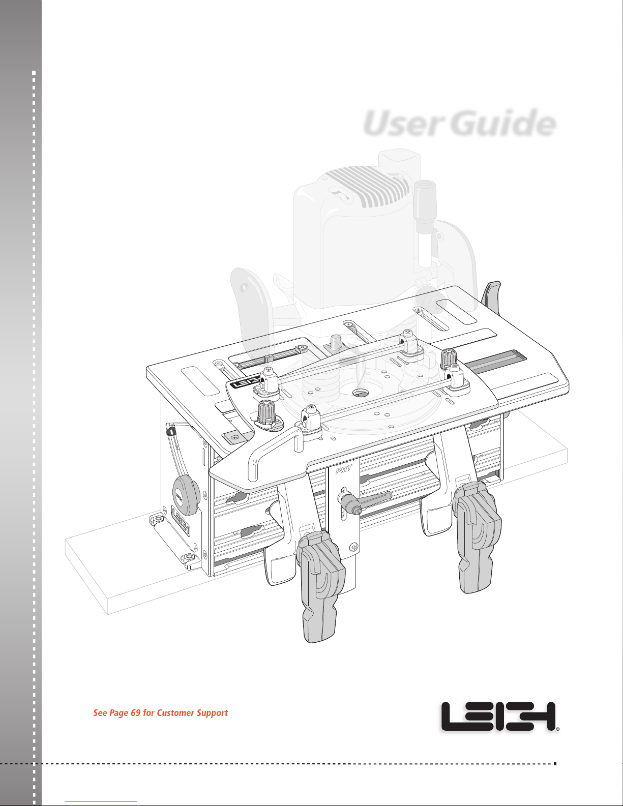
LEIGH FMT PRO
Leigh Router Joinery Jigs
User Guide
Frame Mortise & Tenon Jig
1-800-663-8932
Joining Tradition with Today
Page 2

ii
Frame Mortise & Tenon Jig User Guide
Your New Leigh Frame Mortise & Tenon Jig (FMT Pro)
Congratulations for selecting the unique Leigh FMT Pro, the best
mortising and tenoning jig available. The FMT Pro will allow you
to rout a large range of sizes of mortise and tenon joints with total
control over joint fit.
To gain the most advantage from this unique tool, please read all of
this User Guide; carefully set up the jig following the simple set-up
directions, and thoroughly familiarize yourself with the basic functions
and principles of operation. Use scrap wood before attempting any
actual projects with valuable hardwood.
Customer Support
If you have any questions that are not answered in this user guide, please
call Leigh Customer Support: 1-800-663-8932 in North America or
email: [email protected]. For support contacts in your country of
purchase, see Customer Support on page 69.
Reminder: If at first you don’t succeed, read the instructions!
Important! Inches and Millimeters
The Leigh FMT Pro is available in two models; Inch or Metric. The
only difference is in the guides and bits used, otherwise the jig itself is
identical. Text and illustrations in this English language User Guide
indicate dimensions in both inches and millimeters, with “inches” first,
1
followed by “millimeters” in square brackets, i.e.
⁄2"x 2"[12x50mm].
Do not be concerned that the inch/millimeter equivalents are not
mathematically “correct”. Just use the dimensions that apply to your
guides and bits.
Technical Bulletins
Downloadable pdfs are available at leighjigs.com on the Support page
for these How To’s and more for your Leigh FMT Pro jig:
• Rout Tenons on Extra Wide Boards
• Mortise & Tenon Joints on Shaped Pieces
• FMT Pro/Super FMT – Specialty Guides
1-800-663-8932
Page 3

Contents
Frame Mortise & Tenon Jig User Guide
CHAPTER 1 Mounting the FMT Pro ................................................................. 1
CHAPTER 2 Mounting the Router
................................................................... 3
Fence Rod Mounting .................................................................... 3
Screw Mounting
CHAPTER 3 The FMT Pro Jig
The Clamp Plate and Clamping
The Table
......................................................................................14
Jig Operation Concept
Safety and Router Operation
Wood Preparation
CHAPTER 4 Mortise & Tenon Procedures
Single Mortise & Tenon, Test
Production Procedures
Small Joints
CHAPTER 5 Multiple Joints
Double In Line Joints
Twin Joints
Quadruple Joints
Triple Joints
CHAPTER 6 Workpiece and Joint Options
Different Workpiece Thicknesses
Longer and Shorter Joints
Thicker and Wider Boards
CHAPTER 7 Special Joints
Angled Joints
Through Tenons
Bridle Joints
Asymmetric Tenons
Haunched Joints
Doweling
.....................................................................................54
Appendix I Joint Specifications, Guide and Bit Selection
Joint Specifications
Guide and Bit Selection
Appendix II Jig Adjustments
Appendix III Parts List
......................................................................................63
........................................................................... 8
...........................................................................11
................................................11
...............................................................16
...................................................17
......................................................................19
.....................................................21
.....................................................21
..............................................................27
..................................................................................28
............................................................................31
..................................................................31
...................................................................................33
........................................................................35
.................................................................................37
...................................................41
.............................................41
.........................................................42
.........................................................44
...............................................................................47
..............................................................................47
..........................................................................48
.................................................................................50
....................................................................51
.........................................................................51
.........................55
.....................................................................55
.............................................................57
..........................................................................61
iii
Appendix IV Customer Support
......................................................................69
Page 4
iv
Frame Mortise & Tenon Jig User Guide
Add Leigh Accessories to make your jig even more versatile.
SPECIALTY GUIDES
Square Tenons
Square tenons are often used
for replicating period furniture.
Item 670900
Y-Axis Mortise
In instances when mortises
need to be routed at 90º to the
clamp plate, this guide does
the trick.
Item 6701YAM
Optional Guides, Bits and Accessory Kit
for Great Savings
Joint Guides
Three optional guide sets
are available increasing the
number of joint sizes you
can make to 68! 16 op
tional guides in 1/4", 3/8"
and 1/2" (6, 10 and 12mm) sizes, make a complete set.
Each guide can be purchased individually or as a set for
better value. Buy all three or as part of the accessory kit
below for even greater savings.
-
Item 6720 or 6820
Louver Doors
Make beautiful
louver doors with
these guides and bit.
L/R matching pair
Item 6701LGP
1/4" HSS Louver
Guide Bit, 1/2" shank
Item 168-500
Extra Clamps Save Time
Leigh Surface clamps are identical to FMT Pro clamps. Save time when
switching between mortise and tenon boards. Bonus! This tough,
versatile cam-action clamp can also be mounted on any flat surface, on
any angle or on a table saw. You can never have too many clamps.
Item SHDC1 Surface mount
(one clamp)
1/8" to 3" capacity
Router Bits
8-piece set in HSS or Solid
Carbide opens up your
possibilities for joint sizes.
Item 162-180 or 162-180C
Accessory Kit for Savings
guide set and boxed inch bit set for the best savings.
Includes an 8-piece boxed inch bit set and 16 optional
guides in 1/4", 3/8" and 1/2" (6, 10 and 12mm) sizes for
a complete set.
Visit www.leighjigs.com for more details
Item ACMT or ACMTC
Combine an optional
Routing tenons with mortise board clamps in place
Use on jigs and fixtures
Routing mortises with tenon board clamps in place Use vertically on bench
Page 5
MOUNTING THE FMT PRO
FMT PRO CHAPTER 1
Mounting the FMT Pro
Jig Assembly and Mounting
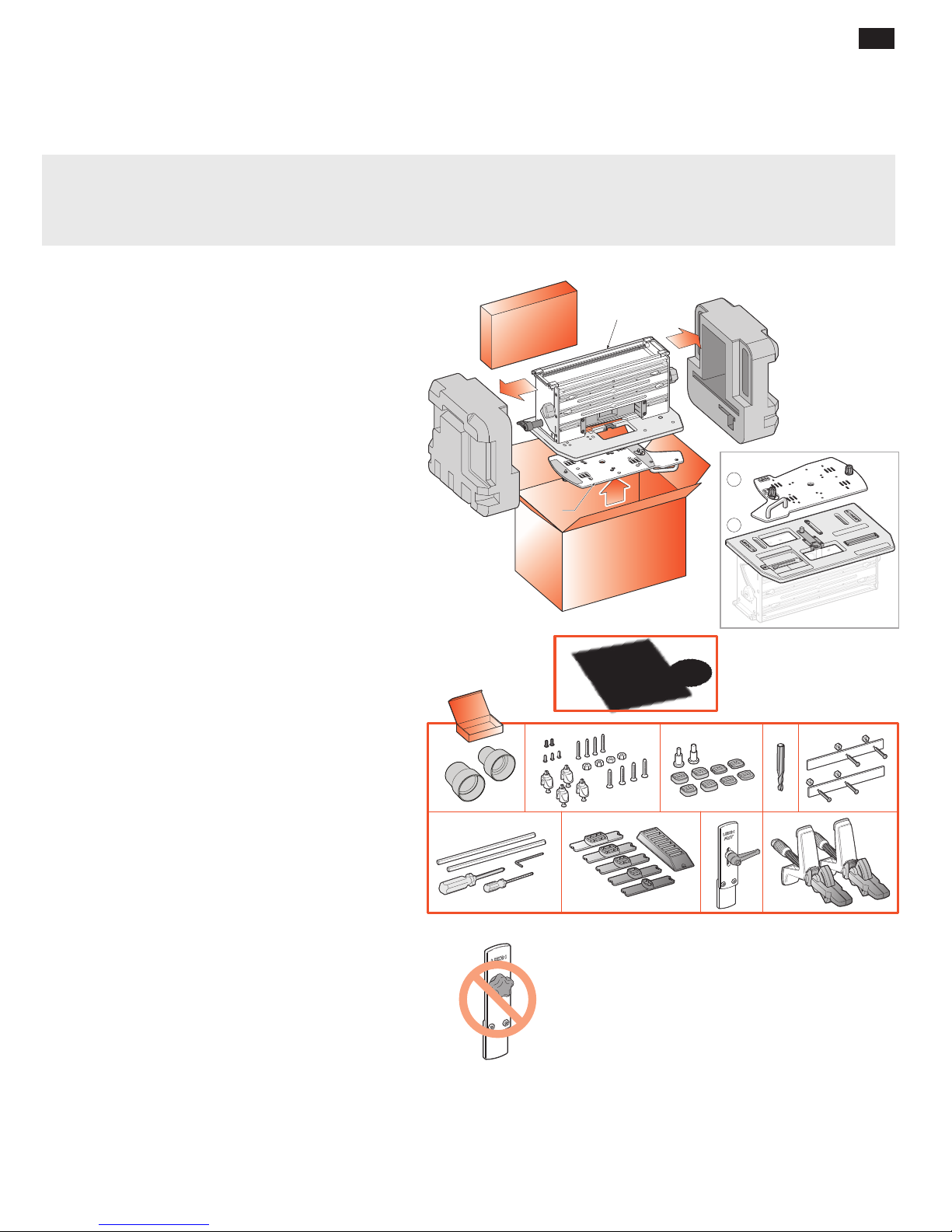
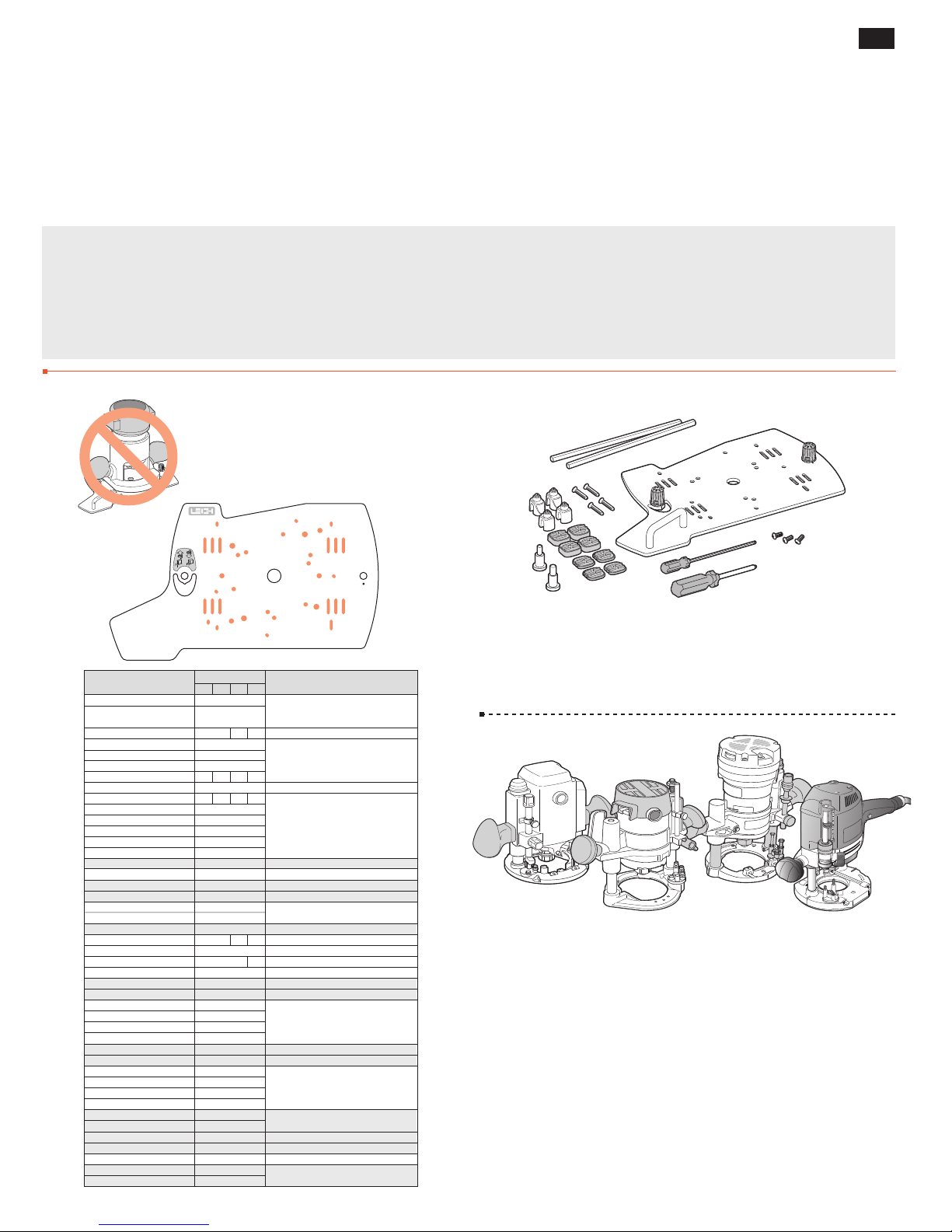
The Leigh FMT Pro comes almost fully assembled with all adjustments factory set — however, before you start to
set up your Leigh FMT Pro Jig, make sure you have received all the required parts.
1. 1 The main Jig Body, complete with:
1 Table
2. 1 Router Sub-Base
3. 1 User Guide
1 DVD Video
4. 1 Box Containing:
A 2 Vacuum Hose Adaptors
B 4 Jig Hold-Down Nuts and Bolts
B 4 U-Posts with 4 Set-Screws and
Four
B 4 1" Countersink Screws
B 3 Hex Socket Button Head Screws 10x24 x
B 2 Hex Socket Button Head Screws M6
C 4 High Shim Spacers
C 4 Low Shim Spacers
C 1
C 1 8 and 12mm Centering Mandrel
D 1
E 2 Outrigger Bars with 4 Screws and Nuts
F 1 Leigh Square Drive Screwdriver
F 1 Leigh
F 1
F 2 Router Hold-down Rods
G 5
& 1 Guide Stand
H** 1 Side Stop Fence with Lever**
I 2 Cam-Action Speed Clamp Assemblies
➀
➁
1
⁄4"-20
3
⁄4"Countersink Screws
1
⁄4"and 1⁄2" Centering Mandrel
5
⁄16" HSS Spiral Upcut 1⁄2" Shank
1
⁄8" Hex Ball Screwdriver
5
⁄64" Hex Key
5
⁄16" guides (or 6x8mm with FMT Pro-M)
1
4
2
2
3
⁄8"
1
3
4
A B C D E
F G H** I
1
VACUUM BOX UPDATE: Most drawings throughout this
user guide show an older version of the vacuum box, clamp
plate and top extrusion. All FMT Pro jigs are shipped with
the newest parts. These changes are reflected in Appendix III.
** SIDE STOP UPDATE: Some illustrations show
the side stop fence with a “knob”. All FMT Pro jigs are
shipped with a side stop fence with a “lever”, (see H in
drawing above).
Note: Any optional accessories that you ordered may also be inside the parts box, or packaged inside the main carton.
If any of these items are missing from your order, please notify your supplier or Leigh Industries immediately.
Page 6
2
Chapter 1 Frame Mortise & Tenon Jig User Guide
"[400mm]
3
4
/
15
1
35/16"[84mm]
1
/2"[13mm]
MOUNTING THE FMT PRO
2
24"[600mm]
5"[125+mm]
4
2
3
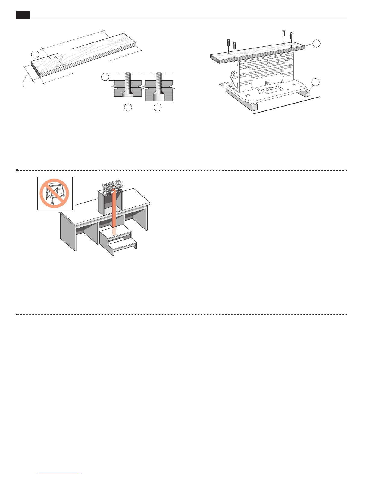
1-1 Mounting the FMT Pro: Prepare a flat board at least
3
⁄4"[20mm] thick, a minimum of 24"x5"[600x125mm]. Drill four
9
⁄32"[7mm] holes on 153⁄4"x35⁄16"[400x84mm] centers, 1⁄2"[13mm] in
from the front edge of the board
if board is thicker, the underside so that the four 1⁄4–20 x 1" long
➂
machine screws will project above the top surface by
. Countersink ➁, or counter-bore
➀
3
⁄8"[9,5mm] ➃.
1
1-2 Turn the jig upside down on two wooden blocks ➀ (to
protect the table and sight knob). Using the four nuts and four
flathead countersunk machine screws, bolt the base board to the jig
1
using the two nut recesses in each end housings. The
front edge
to the front of the jig (of course). Now you can
➁
⁄2"[13mm]
clamp your FMT Pro to any bench.
1-3 For routing long vertical rails it may be necessary to build
a jig stand to mount securely on your bench. Make the stand and
bench height combination sufficient to accept the board length
you have in mind. The jig stand should be bolted securely to the bench.
Make up a stable platform as shown here to stand on. Do not use
a collapsible step stool, these are unstable and unsafe.
■
Page 7
MOUNTING THE ROUTER
FMT PRO CHAPTER 2
Mounting the Router
Fence Rod Mounting
Screw Mounting
Foreword The threaded sub-base mounting holes on many routers are not strong enough for the stresses
produced when routing joints with the FMT Pro, so Leigh developed the Universal Fence Rod Mounting System.
The Leigh FMT Pro Sub-Base provides great attachment strength and lateral anchoring. Depending on your router
model, fitting the Sub-Base to your router may take up to an hour…the first time only. Once fitted, the router
can be removed and reattached in about a minute. Mounting the Sub-Base correctly is critical to the accuracy of
the jig, so take your time and get it right the first time. Here’s how...
Fence Rod Mounting
m The FMT Pro must only be
used with a plunge router. Never,
ever use a fixed base router!
3
Right
Left
6
Rear
Left
Front
ROUTER MAKE HOLES NOTES
AEG OFS 50 2
BOSCH 1450,
1611EVS,1613EVS,1617EVS
BOSCH 1619EVS
BOSCH MRP23EVS
CRAFTSMAN 2
DEWALT 616/618
DEWALT 621
DEWALT 625
ELU 97 1 3 1 3
ELU MOF 131 2
ELU MOF 177/02 2
ELU 3304 3
ELU 3338 2
FESTOOL 900E, 1010 7
FESTOOL OF1400 11
FESTOOL OF2000 2
FESTOOL OF2200 12
FLEX OFT2926VV 5
FREUD FT2000E 2
HITACHI M12V
HITACHI M12VC
HITACHI TR12 2 **8 2 **To avoid Turret
MAKITA 3600B 1
MAKITA 3612BR 3 **6 **To avoid Turret
MAKITA 3612C 3
MAKITA RP 0910 4
MAKIT
A RP 1100 Series
MAKITA RP2301FC
METABO OFE728
METABO OFE1028 3
MET
ABO OFE1229 3
MILWAUKEE 5616
RIDGID 10
RYOBI R-150 3
RYOBI RE180PL 2
RYOBI R-500 2
RYOBI R-E600 2
PORTER CABLE 693
PORTER CABLE 890, 893
PORTER CABLE 893 Type 2
PORTER CABLE 7529, 8529 5
PORTER CABLE 7539 *2 *Reverse U-Post to put screws outside rods
TRITON, TRC001 3
TRITON, MOF 001 2
1
/4hp
1
/4hp
9
2
3
1
4
11
10
7
3
2
1
9
12
8
6
LR RR LF RF
2
1 *1 1
1
3
1 3 1 3
2
2
4
4
2
3
4
4
10
4
9
9
5
7
Rear
10
5
7
*File notch in U-Post if req’d to avoid Turret
Requires 1/16" packing shim. See 2-9
Use 2 #5130 screws provided. See 2-30
Use 2 #5130 screws provided. See 2-30
Use 3 #6410 screws provided. See 2-30
Use 3 screws from router base. See 2-30
Use 3 screws from router base. See 2-30
Use 3 screws from router base. See 2-30
Use 3 screws from router base. See 2-30
Use 3 #6410 screws provided. See 2-30
Use 3 #6410 screws provided. See 2-30
Use 3 #6410 screws provided. See 2-30
Use 4 No.6677 1/4-20 x 3/8" button
head socket screws
6
9
12
123
4
5
7
11
9
10
4
123
6
Right
Front
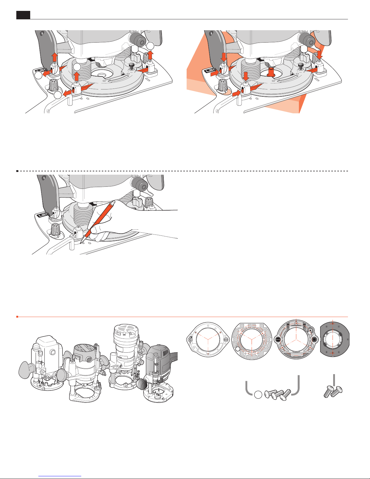
2-1 The Leigh FMT Pro Sub-Base Place your router, the
FMT Pro Sub-Base and all the mounting parts on a clear bench.
From the Sub-Base diagram and chart on this page, find the make
and model of your router.
2-2
Mark the appropriate mounting holes on the Sub-Base. Use a
non permanent medium e.g. chalk, sticky tape (ink will permanently
stain the anodized surface).
Note: If the chart at left indicates your router is a “Screw
mount” (routers in shaded rows) go directly to 2-30. If your
router is not listed here, proceed to 2-3. For the most up-todate list of routers, go to www.leighjigs.com.
Page 8

4
Chapter 2 Frame Mortise & Tenon Jig User Guide
1
MOUNTING THE ROUTER
2-3 If you have a plunge router that is not listed in the Sub-Base list,
it is essential that your router have two parallel fence rod holes through
5
the router base. These must be at least
⁄16"[8mm] in diameter ➀. Fit
the correct shank sized centering mandrel to your router, place it on the
Sub-Base and plunge the mandrel into the base hole. Place the fence rods
through the rod holes with an equal amount protruding at each end.
2
1
3
2
3
1
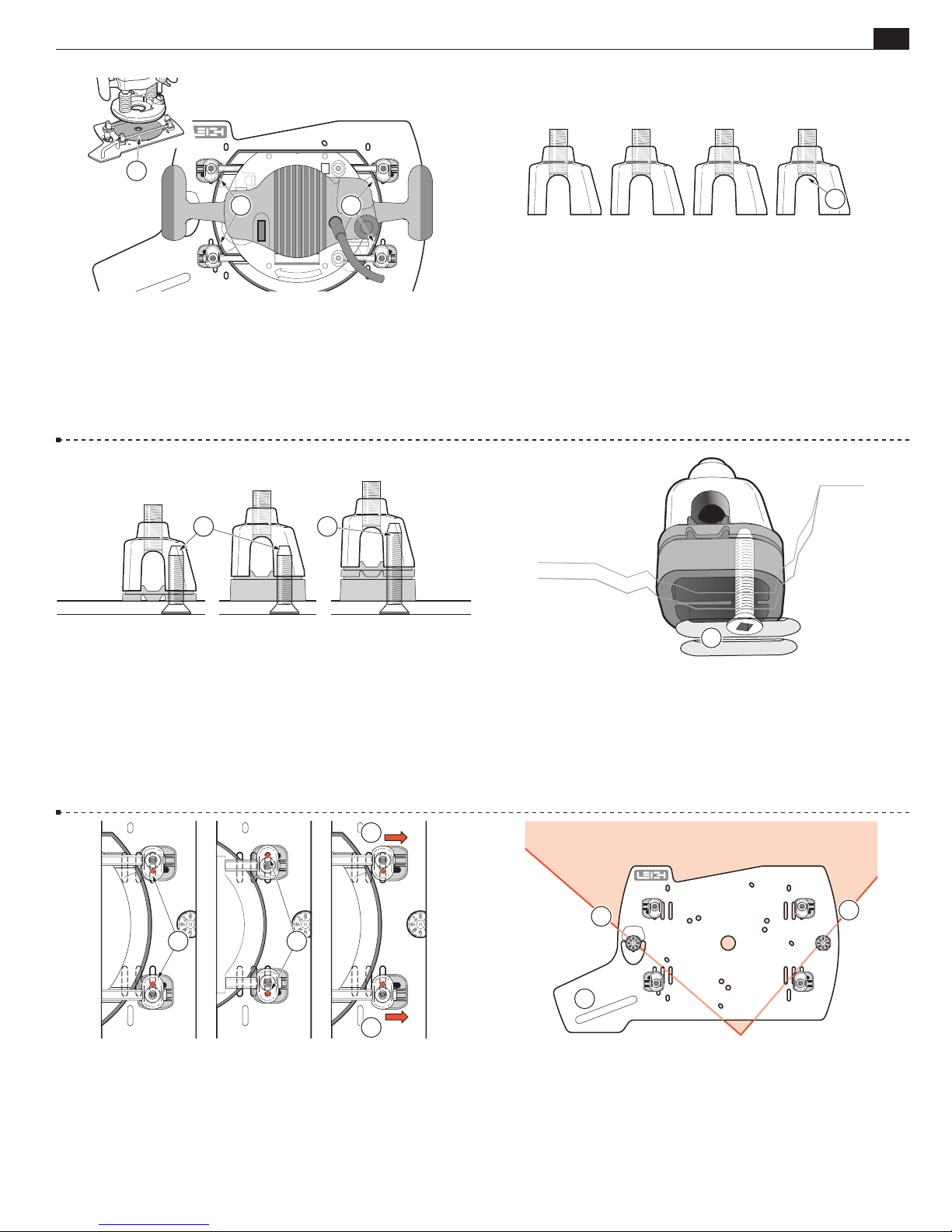
2-5 Most plunge routers will be mounted to the Sub-Base like this,
with rods through the fence rod holes
U-Posts
, but it is essential that the correct shim spacers ➂ are
➁
and clamped down with the
➀
selected.
2-4 Take the four U-Posts and by trial, establish which four
Sub-Base slots or holes will serve to attach the U-Posts. Mark these
with chalk or sticky tape and follow instructions 2-5 through 2-29.
1
2
3
2-6 Depending on the make and model of your router, the height
between the underside of your router and the bottom of the rod
will vary. This dimension will determine if you need to
hole
➀
use low
or high ➁ shim spacers, or possibly both together ➂.
➀
1 2
2-7 To measure the “rod height”, place the router on a bench.
Either use a calliper
, or insert a rod (flat side up) and use a good
➀
rule to measure between the bench top and the bottom of the
.
rod
➁
1 2 3
0
10
20
30
40
50
2-8 If rod height is between 3⁄16"[4,5mm] and 3⁄8"[9,5mm],
use low shim spacers
17
⁄32"[13,5mm], use high shim spacers ➁. If rod height is between
17
⁄32"[13,5mm] and 3⁄4"[19,5mm], use both shim spacers ➂, with
. If rod height is between 3⁄8"[9,5mm] and
➀
the high one on the bottom. Note: If the rod height is less than
3
⁄16"[4,5mm], see 2-9.
Page 9
MOUNTING THE ROUTER
2
Chapter 2Frame Mortise & Tenon Jig User Guide
5
11
2-9 Note: Use of the shim stops is essential, not only to provide the
correct rod height but to also act as side-to-side stops for the router
3
If the rod height of your router is less than
⁄16"[4,5mm] you must
➀
provide a shop-made packing shim between the router and Sub-Base.
We suggest one or more sheets of sandpaper
, rough side up. Don’t
➁
forget the center hole.
1 2
1
2-10 Adjust the four U-Post set-screws with the set-screw end
.
flush inside the arch of the posts
➀
.
1
2-11 There are two lengths of U-Post screws; 3⁄4"[19mm] and
3
1"[25mm]. The
measure. Use these for either the low or high shim spacers
⁄4"[19mm] are factory fitted as a quality control
➀
Change them for the 1"[25mm] screws if both shim spacers are
.
used
➁
3
1 2
3
2-13 In most cases, position the U-Post screw leg to the inside
of the rod
base, to the outside
position
or depending on the size and shape of the router
➀
. Slide the shim-stops away from the router
➁
. These will be repositioned against the router later.
➂
2-12 Using the four selected screws, lightly attach the four U-Posts
and correct shim-stop combination through the previously marked
.
slots or holes in the Sub-Base. The screws must enter from below
. Only very lightly tighten; you will need to move the U-Posts
➀
and the shim-stops during setup.
2
1
2
2-14 Place the Sub-Base flat down on the corner of a smooth
bench, the handle to your near left
ing the adjacent edges of the bench
and the guide pins touch-
➀
.
➁
Page 10
6
Chapter 2 Frame Mortise & Tenon Jig User Guide
1/4"
8mm
MOUNTING THE ROUTER
1
1/2"
12mm
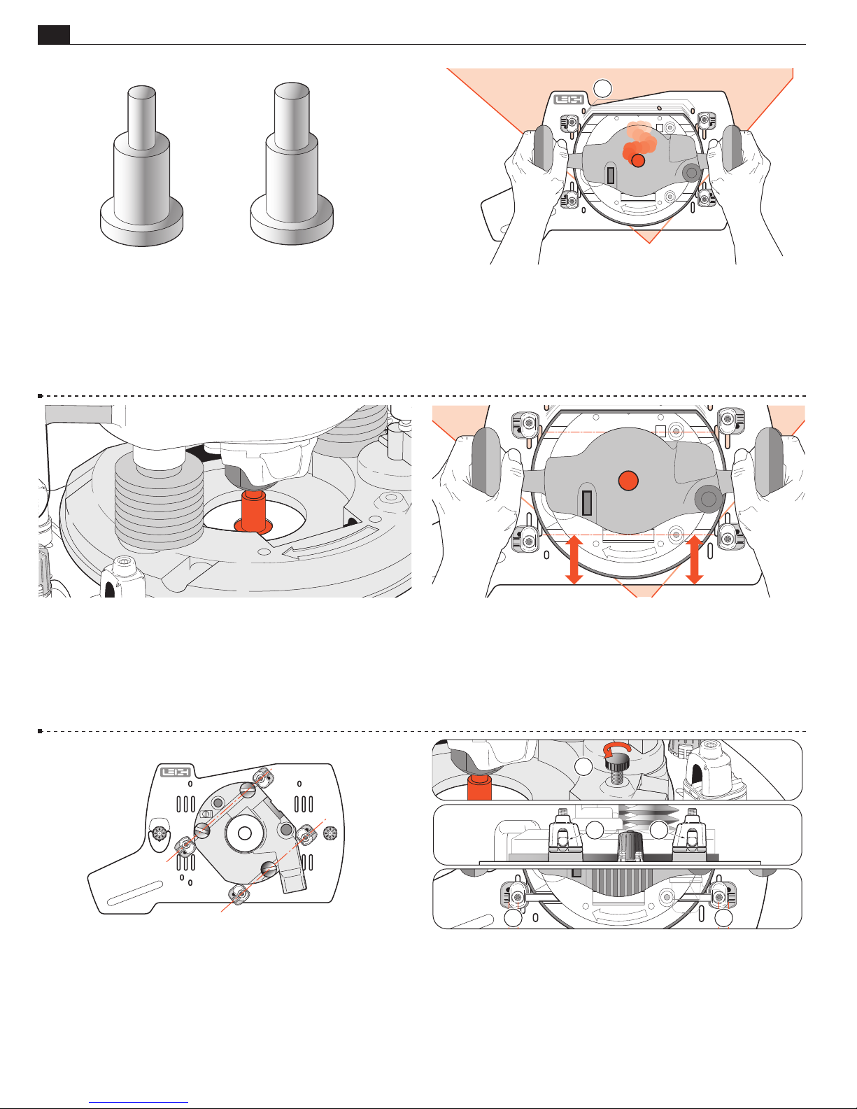
2-15 Unplug the router.
Note the collet size of the router. Choose the matching size centering mandrel and fit it into the router collet.
2-16 Holding the router as you would in normal use, place it base
down onto the Sub-Base; the rear of the router toward the rear of
the Sub-Base and large notch
. Plunge and move the router so
➀
that the large diameter of the centering mandrel fits through the
Sub-Base center hole
…
2-17 …and touches flush to the bench. Lock the plunge.
m Concentricity of bit to Sub-Base bit hole is essential to FMT
Pro accuracy, so never mount the router without using the centering mandrel.
2-19 Festool 900 and 1000 Series:
Align the fence rod holes to the previously positioned U-Posts.
2-18 Align the router so that the fence rod holes are parallel to the
front edge of the Sub-Base (except Festool 900 and 1000 Series,
see 2-19).
1
22
3 3
2-20 Loosen and raise any router fence rod knobs ➀. Move the U-Posts
and adjust as necessary to slide the two hold-down rods through the
➂
➁
.
. Leave
U-Posts and router fence rod holes, flat side of rods on top
an equal amount of rod projecting through each U-Post
m Never use the router’s fence rod knobs
to “help” secure the router.
➀
This places uneven pressure and could damage the router base.
Page 11
MOUNTING THE ROUTER
1
Chapter 2Frame Mortise & Tenon Jig User Guide
7
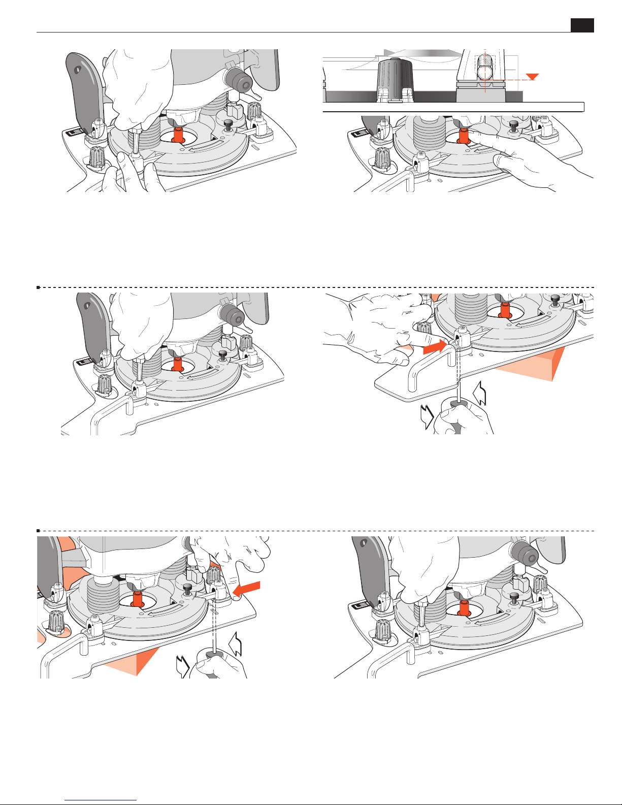
2-21 Using the hex screwdriver, turn down the four U-Post setscrews until there is only very slight and even pressure on each
end of both rods. Leave the shim stops in the outer position.
2-23 Tighten the top U-Post set-screws a little more securely to
hold the bars and router.
2-22 Check that the rods are still centered in the rod holes ➀ and
check that the router collet can rotate without excessive binding in
the Sub-Base hole. Mandrel touching side of hole is OK; mandrel
binding tight is not! Move the router if required to allow mandrel
to rotate.
2-24 Slide the router/Sub-Base assembly on the corner of the
bench so that one U-Post bottom screw is overhanging the edge.
Loosen this screw just slightly (if necessary) to take any pressure
off the shim spacer above. Push the Shim spacer in to touch the
router base and, holding it in position against the router base,
firmly tighten this bottom screw.
2-25 Repeat this procedure at the other end of the same rod to
position the shim stop against the router base. Re-check the collet/
mandrel for relatively free rotation. Turn the router around on the
corner of the bench and repeat this procedure on the two U-Post
assemblies on the second rod.
2-26 Tighten the four U-Post set-screws to the rods. The hex driver has
high leverage so use common sense when tightening. The rods will bow
slightly. Objective: have the collet concentric to the bit hole; the four shim
stops providing secure side thrust security, and the U-Posts clamping the rods
which hold the router against the Leigh Sub-Base. Router /Sub-Base are now
a unit. Release the plunge; remove and store the mandrel. You’re set to go.
Page 12
8
Chapter 2 Frame Mortise & Tenon Jig User Guide
1
1
2
2
MOUNTING THE ROUTER
2-27 Here’s how to remove the router for use elsewhere:
Loosen the four top U-Post set-screws
Slide out the two rods ➁.
➀
Do not remove the U-Posts. In about a minute, the router is free
to be used for other tasks.
2-29 Hint: If you plan to fit a different make/model router and
later use the current one again, you can greatly speed up the reinstallation of the first router by marking around the original four
U-Post/shim-stop positions.
■
2-28 To re-mount the router: place the Sub-Base over the corner
of the bench. Make sure surfaces are clean. Place the router on the
Sub-Base with the centering mandrel in the center hole. Insert
the fence rods. Evenly tighten the four U-Post set-screws. Check
that the mandrel rotates freely. In about two minutes the router/
Sub-Base assembly is ready for making mortises and tenons.
Screw Mounting
2-30 These routers do not have suitable through fence rod holes:
Porter Cable 693, 890, 890 Type 2, 893, 7529, 8529; Flex OFT
2926VV; Festool 1400, 2200; Makita RP0910, Makita RP1100
series; Triton TRC001, MOF001. We’ve provided Sub-Base holes
and screws to mount these directly to the Sub-Base. Using Porter
Cable 7529 and 8529 as examples, here’s how.
PORTER CABLE
693
890
890 Type 2
893
PORTER CABLE
7529 and 8529
(FLEX OFT2926VV)
1
MAKITA
RP1100 SERIES
FESTOOL
1400 and 2200
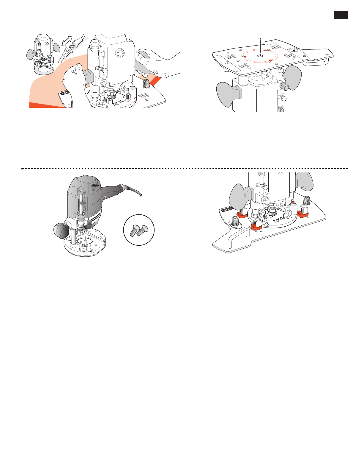
2-31 Note: Porter Cable 7529 & 8529 (Flex OFT2926VV) have
two sets of 3 threaded holes. Use the inner circle of FMT Pro Sub-Base
holes. The outer circle holes align with threaded holes, but are not deep
enough for the screws. For Porter Cable (Flex) 693 & Makita RP1100
series routers use the outer circle of Sub-Base holes. Firmly attach
the Sub-Base using the three 6410 hex socket button head screws
provided
. Do not use the router’s Sub-Base screws. See 2-32.
➀
Page 13
MOUNTING THE ROUTER
Chapter 2Frame Mortise & Tenon Jig User Guide
9
2-32 Unplug the router. Remove the router’s plastic Sub-Base (except
Festool 1400) and template guidebush adaptor from 7529 or 8529.
Remove the clear plastic dust cover from 8529 router base top (screw
holes are used to attach Leigh FMT Pro Sub Base). Store removed parts
for future use. Fit the correct shank sized centering mandrel to collet.
With the Leigh Sub-Base on a flat bench corner, place router on top
and plunge mandrel through to bench and lock the plunge.
5130
2-34 Festool 1400 series routers attach using the two No. 5130 screws
provided, through base holes No. 11. Festool 2200 series routers attach
using the two No. 5130 screws in the No. 12 holes.
2-33 Remove the router and stand it upside down on the bench.
Depending on the router design, you may need to support it in
a soft-padded vise. Place the Sub-Base upside down onto the
router’s metal base with the mandrel centering the router to the
base through the bit hole. Rotate the Sub-Base until the correct
threaded screw holes in the router base align with the counterbored holes in the Sub-Base.
2-35 m In addition to the base screws it is vital to attach the four
U-Posts and four of the shim stops (either size) and position and
tighten these against the edge of the router base to prevent lateral
router movement. Note: You do not use the fence rods. For correct
positioning, see 2-16 through 2-18, 2-24 and 2-25. Note: Porter
Cable 7529 and 8529 handles will be slightly angled (not parallel)
to the FMT Pro Sub-Base.
■
Page 14

10
Chapter 2 Frame Mortise & Tenon Jig User Guide
MOUNTING THE ROUTER
Page 15
THE FMT PRO JIG
11
FMT PRO CHAPTER 3
The FMT Pro Jig
The Clamp Plate and Clamping
The Table
Jig Operation Concept
Safety and Router Operation
Wood Preparation
The Clamp Plate and Clamping
0
10
4
2
20
30
3
1
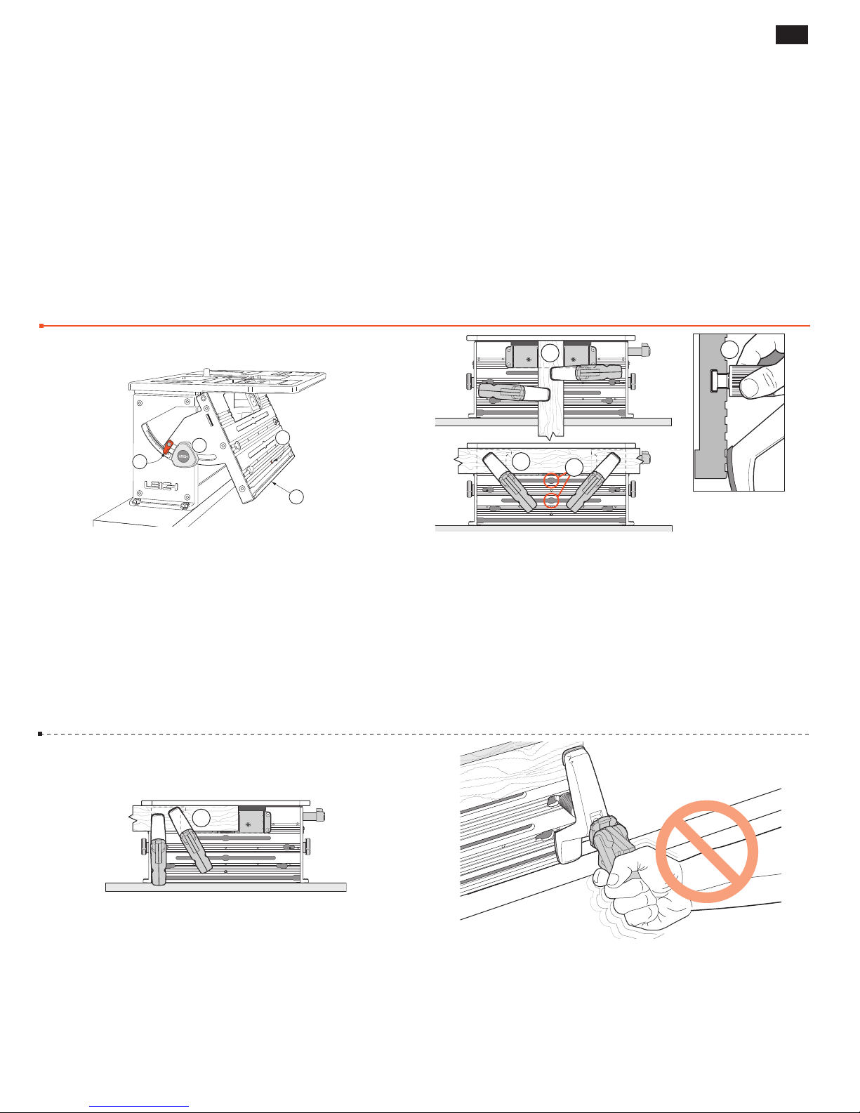
3-1 The clamp plate ➀ is adjustable up to 30˚ from vertical and
is held securely by two quadrant knobs
. A set-screw ➂ allows for
➁
positive return to 90˚. To ensure flush and in-plane joints, it may
be necessary to adjust the clamp-plate angle. See Appendix II, Jig
Adjustments. An angle scale is provided, with an indicator adjustable
➃
.
to zero
m The clamp plate and cam-clamps are a self contained clamping
area. Under no circumstances should any other jig component be
used for clamping and no auxiliary clamping method used, other
than as illustrated in this guide.
2
3
1
1
3-2 The two clamps are powerful cam-action rocking-arm
clamps with capacity from zero to 3"[76mm]. The T-bolt is inserted
directly into the T-slot opening
, moved to desired position and
➀
brass thumb nut lightly tightened. Normally tenon workpieces
will be clamped vertically
like this
➂
, or...
, and mortise workpieces horizontally
➁
3
3-3 …like this ➂. For clamping very small workpieces see
Chapter 4, Small Joints.
3-4 Never force a cam-action clamp. It has great leverage, and
using excessive force may damage the workpiece. The powerful
clamp, combined with a non-slip clamping surface, requires only
moderate clamping pressure to hold the workpiece securely in
place.
Page 16
12
Chapter 3 Frame Mortise & Tenon Jig User Guide
THE FMT PRO JIG
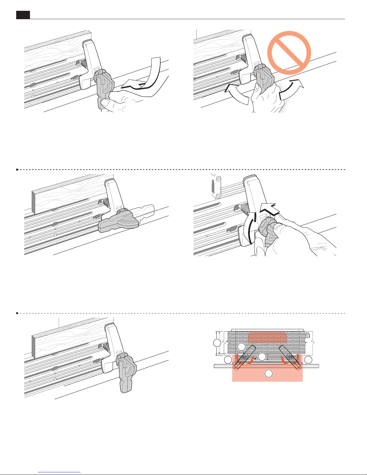
3-5
A smooth, firm action is enough to engage the clamp.
Rule of thumb: if you can’t throw the lever comfortably by strong
thumb pressure, reduce the tension. A few minutes of trial and error
testing will soon give you the feel for the correct clamp tension.
3-7 The clamping pressure is the same whichever of the two
directions the lever is thrown. But if the lever is uncomfortably
positioned at the correct clamping pressure...
3-6
Do not use the lever as a torque arm!
Adjust the clamp pressure only with the clamp disengaged.
3-8 ...release the clamp, remove the workpiece and turn the
step-washer a quarter turn. The step height in the step-washer is
one quarter of the thread pitch.
3-9 Then adjust the clamp until the lever is in the correct position at the required pressure.
2
1
4 4
3
4
3-10 The clamp T-Bolt Slots and “keyholes” allow for full clamping coverage. The two lower keyholes
to clamp mortise boards between 4
wide
. Always clamp with the heel and toe of the clamp over
➁
the surface area of the clamp plate
m Never allow the clamp arm heel pad in these red shaded areas
are for the rare requirement
➀
3
⁄4"[120mm] and 51⁄2"[140mm]
.
➂
➃
even if (particularly if) the mounting board or bench is there.
,
Page 17
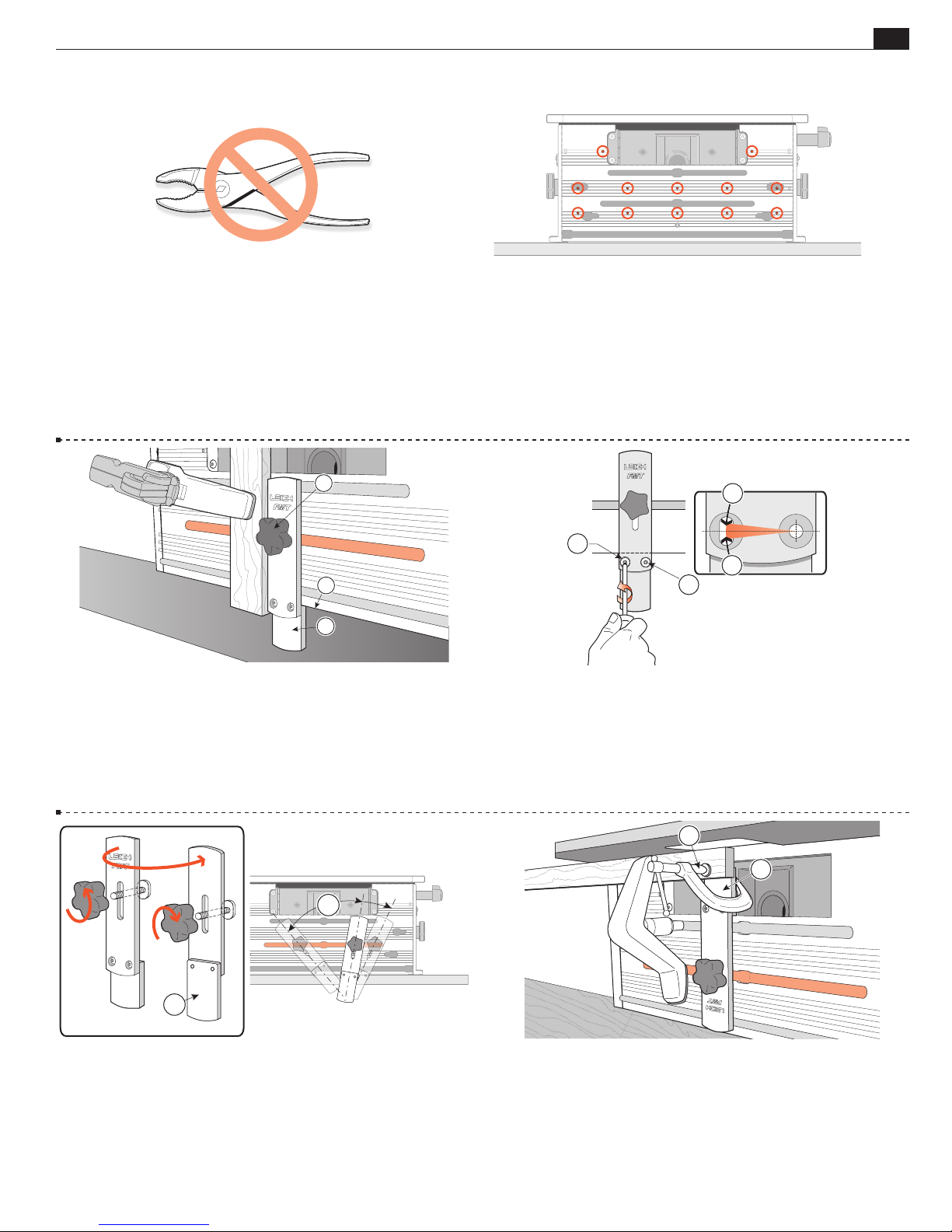
THE FMT PRO JIG
Chapter 3Frame Mortise & Tenon Jig User Guide
13
3-11 The clamp T-bolts nuts need only be lightly finger tightened
to prevent accidental clamp movement. The nuts are knurled to
provide a good finger grip.
Never use a tool to tighten these nuts!
1
3
2
3-13 The FMT Pro’s sidestop fence is attached in all modes by a
single knob and T-bolt inserted to the center clamp plate slot
➀
Most tenon pieces are routed vertically, and for that purpose the
short part of the fence
clamp plate
. In this mode the Leigh logo faces toward you.
➂
acts as a T-square against the edge of the
➁
3-12 The clamp plate is provided with twelve through-holes.
If for any reason a facing board is required to be attached to the
clamp plate, No.8 or M4 wood screws (not supplied) may be used
from the rear. See chapter 4, Small Joints.
3
1
3
2
3-14 The sidestop fence is squared at the factory, but check your first
.
test joints. If your router/bit is not perfectly perpendicular to the table
adjust the sidestop fence: slightly loosen the 'pivot' screw
screw
. Adjust the angle ➂ to match the bit and retighten. Rout test
➁
and the 'lock'
➀
joints to confirm correct setting. Once locked in this position it should
never need adjusting when used with that same router.
1
3-15 Angled Joints: Remove the knob and T-bolt. Reverse the fence so
the short end faces toward you
along the center clamp plate slot
. The fence may now be set at any angle
➀
by tightening the knob.
➁
m NOTE: Never rout tenons with the short part of the fence to the top, in
the bit opening.
2
1
2
3-16 'Mortise steady': When routing mortises in small stock the piece
may 'flutter' causing poor joint fit. Invert the fence with the short end
up in the bit opening
short fence
which is perfectly flush with the clamp plate face ➀. When
➁
. Clamp the mortise piece against the face of the
➀
routing mortises at the end of a board, always move the table as far as
possible left or right to minimize the length of unsupported workpiece.
Page 18
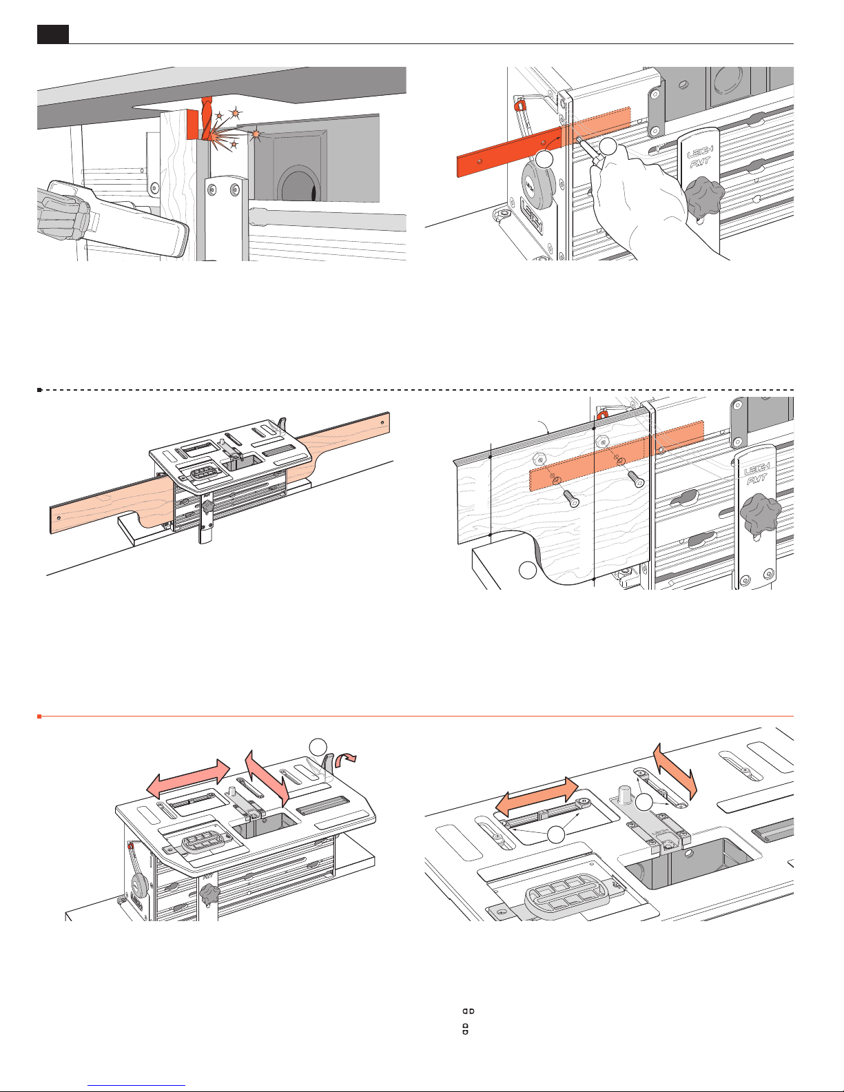
14
6"[150mm]
LR
FB
1
1
LR
FB
Chapter 3 Frame Mortise & Tenon Jig User Guide
THE FMT PRO JIG
3-17 m WARNING: Never rout tenons with the sidestop
fence in the inverted position (with the short end up in the bit
opening). The inverted fence mode is only used to support small
mortise stock.
1
2
3-18 The jig clamp plate has an opening on each outer edge in
which to fit the included “outrigger bars”
by set-screws
tightened with the hex driver.
➁
3
/8"[10mm]
3"[75mm]
. The bars are retained
➀
3-19 The outrigger bars allow for attachment of shop-made outrigger beams on which to mount sidestops or add pencil marks. This
makes for efficient routing of multiple mortises. See Chapter 4,
Production Procedures.
The Table
1
3-21 The table is clamped in any desired position by the Table
Clamp
. Turning the clamp lever up 90˚ releases the table,
➀
which can then be moved in any direction to any position within
its range. Clamp tension is factory preset. See Appendix II, Jig
Adjustments.
1
3-20 The outrigger beams should be 3⁄8"[10mm] plywood, shaped
as suggested to minimize weight. Drill as shown and attach with
the small nuts and bolts provided. The top edge should just clear
the underside of the locked table. Store the outriggers on a wall
hanger when not in use. The deep shoulder
lever support against the end of the clamp plate assembly.
provides canti-
➀
■
3-22 Adjustable Limit Stops ➀ are used to limit or prevent table
movement left to right (X-axis) and front to back (Y-axis), and
to precisely align double and quadruple mortises and tenons (see
Chapter 4). Use Limit stops when you see these icons:
for left-to-right table movement
for front-to-back table movement.
Page 19
THE FMT PRO JIG
4
3
1
2
1
2
Chapter 3Frame Mortise & Tenon Jig User Guide
15
1
2
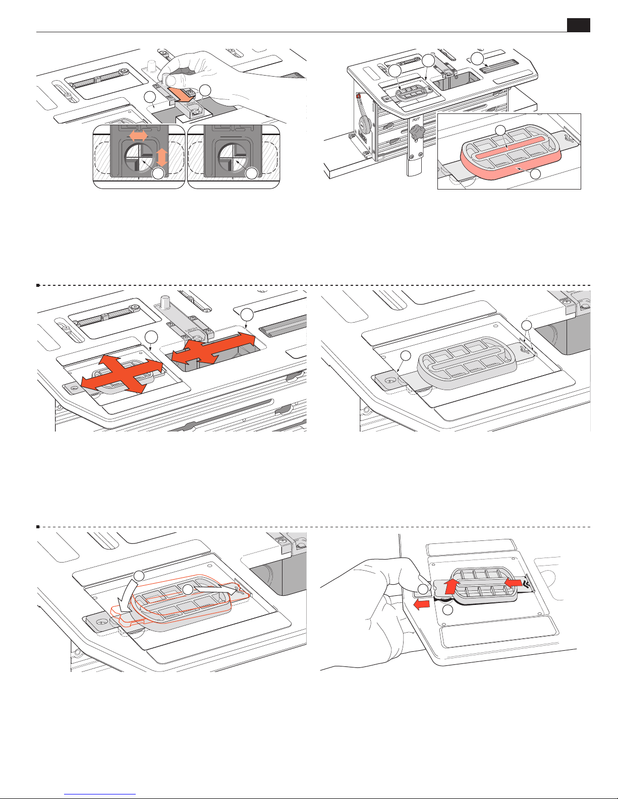
3-23 The table has a bit opening ➀ and Joint Aligning Sight ➁. Pulling
the sight fully forward to its detent provides precise table positioning over
joint cross-marks
. Because the human eye excels at comparisons, we can
➂
perceive differences as small as 0.004" in the space between the edges of the
line and the triangles
sight using slight table movements until the spaces appear the same
. That’s 0.002" off center! You can readily center the
➂
➃
2
1
.
2
3
1
4
5
3-24 To the right front is the right-hand “Pin Track” ➀. The right-
hand router sub-base Guide Pin runs in this track in all routing
operations. To the left front is the Guide Recess
Joint Guides
Pin runs in the guide slot
outside of the Guides
are placed. The left hand router sub-base Guide
➂
for cutting mortises or around the
➃
, for cutting tenons.
➄
, in which all
➁
3-25 The Guide Pin cannot move horizontally outside the
recess
opening
3-27 Snap the Guides in like this.
Use firm pressure just next to the guide latch.
Note: The guides are injection molded acetal and the guide bases
may vary slightly in tolerance. Some may require more pressure
, and prevents the bit from touching the sides of the bit
➀
.
➁
to insert. The tighter guides will become easier after a few insertions.
3-26 Two small projections on the Guide fit into undercuts on
the right side of the guide recess
pushed down and retained by the spring-loaded Guide Latch
. The left end of the Guide is
➀
➁
m Note: the guide end shapes are not identical. Guides can
only be installed one way as shown here.
1
2
3-28
To remove a Guide, pull back the latch ➀ and push through
the finger-hole from below with your fingertip
➁
.
.
Page 20
16
1
2
Chapter 3 Frame Mortise & Tenon Jig User Guide
3
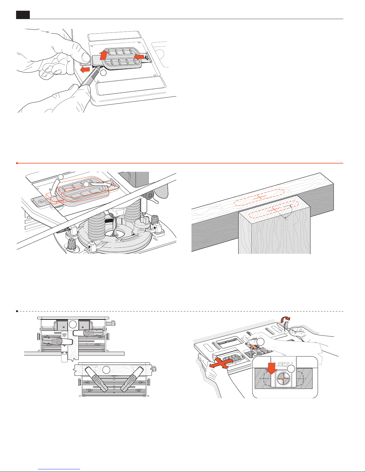
3-29 If the finger-hole is not accessible from below, use your fingernail or a small non-metallic pry to lift the Guide up
Jig Operation Concept
➂
.
■
THE FMT PRO JIG
3-30 The selected guide is placed into the guide recess and the
matching bit fitted to the router.
1
2
90˚
3-31 The centers of a mortise and tenon are marked with a cross.
1
1
3-32 Tenon workpieces are usually clamped vertically ➀. Mortise
workpieces are always clamped horizontally
➁
.
3-33 The jig table is centered over the marked workpiece with
the extended sight
➀
.
Page 21
THE FMT PRO JIG
2
Chapter 3Frame Mortise & Tenon Jig User Guide
1
17
3-34 Tenons are routed with the guide pin running around the
outside (tenon) part of the guide
. See Chapter 4 for routing
➀
techniques.
Safety and Router Operation
3-36 Read the owner’s manual that came with your router. It is
essential to understand the router manufacturer’s instructions
completely.
3-35 Mortises are routed with the guide pin running in the inside
mortise part of the guide
. Always rout the mortise slightly deeper
➁
than the tenon length.
Note: Only one tenon and perhaps two mortises need to be marked
and sighted. Please read all of the procedural chapters to gain the
utmost efficiency from your FMT Pro.
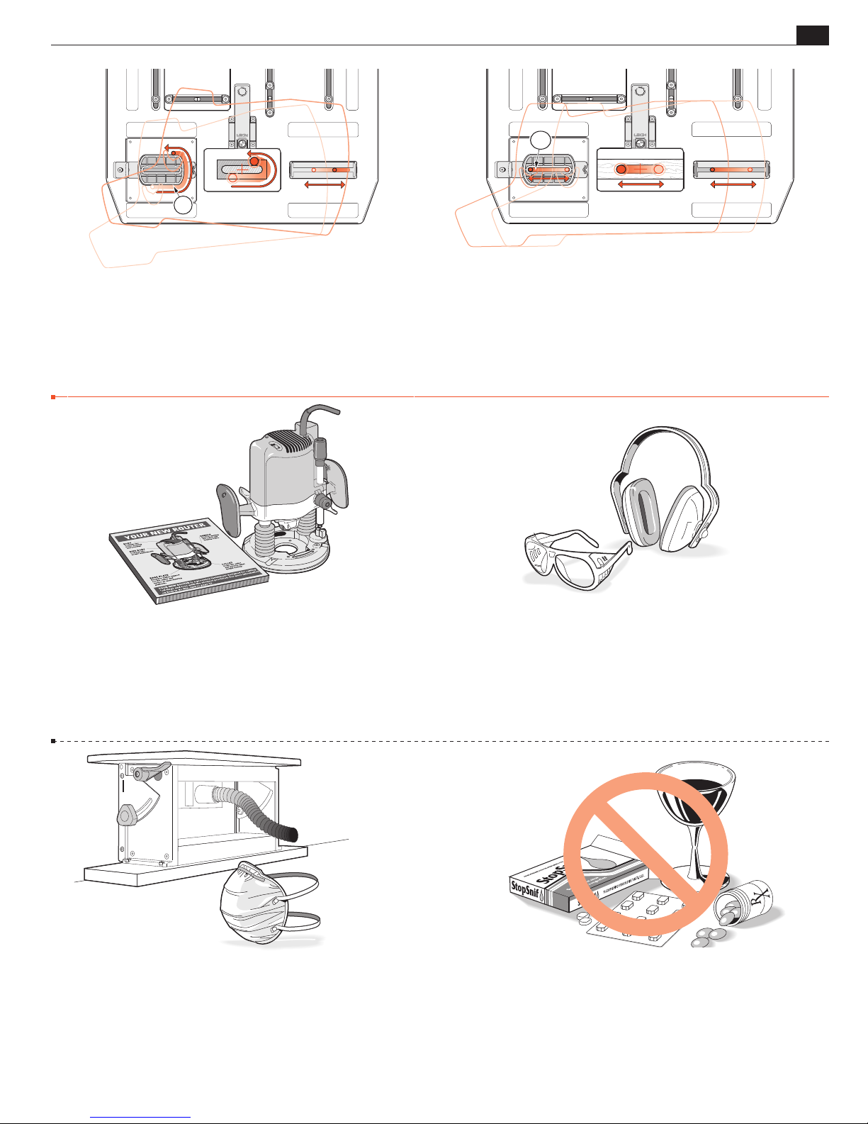
■
3-37 Always wear approved safety glasses.
Always wear hearing protection.
3-38 Protect yourself from harmful dust by wearing a face mask.
Connect your shop vacuum or dust collection system to the FMT
Pro whenever possible.
3-39
Never drink alcohol or take medications that may
m
cause drowsiness when you will be operating a router.
Page 22
18
Chapter 3 Frame Mortise & Tenon Jig User Guide
THE FMT PRO JIG
1
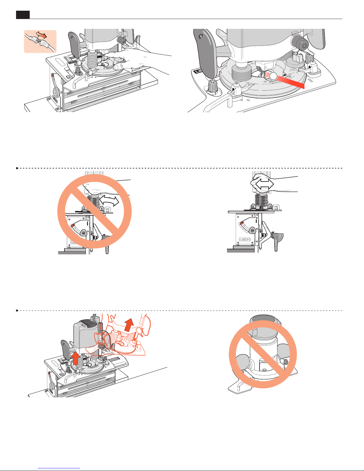
3-40 Always disconnect the power source from the router when
fitting bits, or making adjustments.
Before connecting the router to the power source, make sure the
bit revolves freely through the Sub-Base bit hole, and table and
3-41 Make sure the router collet does not contact the FMT Pro
Sub-Base at full plunge cuts. Set the router plunge stop rod as
necessary to prevent this
➀
.
clamp plate bit openings in all extreme guide pin positions and
preset bit depths.
3-42 Do not tilt the router on the jig. 3-43 Keep the router flat on the jig assembly.
3-44 Always raise the plunge router mechanism before removing
the router assembly from the jig.
3-45 Never, never, use a non-plunge fixed base router on the
FMT Pro.
Page 23
THE FMT PRO JIG
Chapter 3Frame Mortise & Tenon Jig User Guide
19
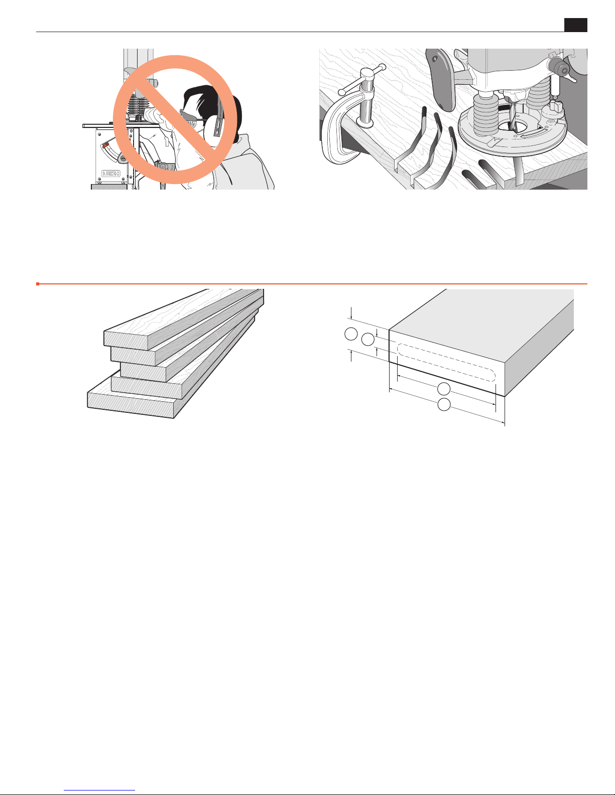
3-46 Do not rout at face level. 3- 47 If you have never used your router before, be sure to follow
the router manufacturer’s instructions for its use. Make plenty
of simple open-face practice cuts before you try to use the router
on the Leigh FMT Pro.
Wood Preparation
■
3-48 Stock for use on the Leigh FMT Pro should generally be
straight, flat, of even thickness and width with square ends and
edges, except where design issues dictate otherwise.
Please note that even small ridges (caused by damaged planer blades) can cause noticeable misalignment of “flush” joint
faces.
1
2
4
3
3-49 You will want to test the jig, so prepare some stock with a
thickness
of about 2½ to 3 times the bit diameter ➁,
➀
For example:
1
⁄4" [6mm] bit 5⁄8" to 3⁄4"[15-19mm]
5
⁄16"[8mm] bit 3⁄4" to 15⁄16"[20-24mm]
3
⁄8"[10mm] bit 15⁄16" to 11⁄8"[25-30mm]
1
⁄2"[12mm] bit 11⁄4" to 11⁄2"[30-36mm]
and a stock width
selected guide length
of say, 1½ bit diameters greater than the
➂
.
➃
■
Page 24

20
Chapter 3 Frame Mortise & Tenon Jig User Guide
THE FMT PRO JIG
Page 25
Routing Procedures
Production Procedures for Small Joints
See Appendix I for complete joint specifications and guide and bit selection
MORTISE & TENON ROUTING PROCEDURES
21
FMT PRO CHAPTER 4
Mortise & Tenon
Single Mortise & Tenon, Test
Production Procedures
Routing Joints Smaller than 1/4"
Before using your Leigh FMT Pro you must
have completed all of the preparatory
steps including reading the router safety
recommendations on the previous pages.
If you haven’t done so, it is essential that
you do it now.
Single Mortise & Tenon, Test
m IMPORTANT SAFETY NOTE
Take great care to not “trap” the bit against the side of tenon
. Do not attempt to rout center tenons in rails thicker than
D
rails
➀
5
/16"[34mm] before referring to 5-39 through 5-44.
1
Without using the table movement as prescribed, the bit would
have to be plunged into the side of the tenon rail causing the bit
to powerfully “drive” the router across the jig. This could be
dangerous and can damage the jig.
1
90˚
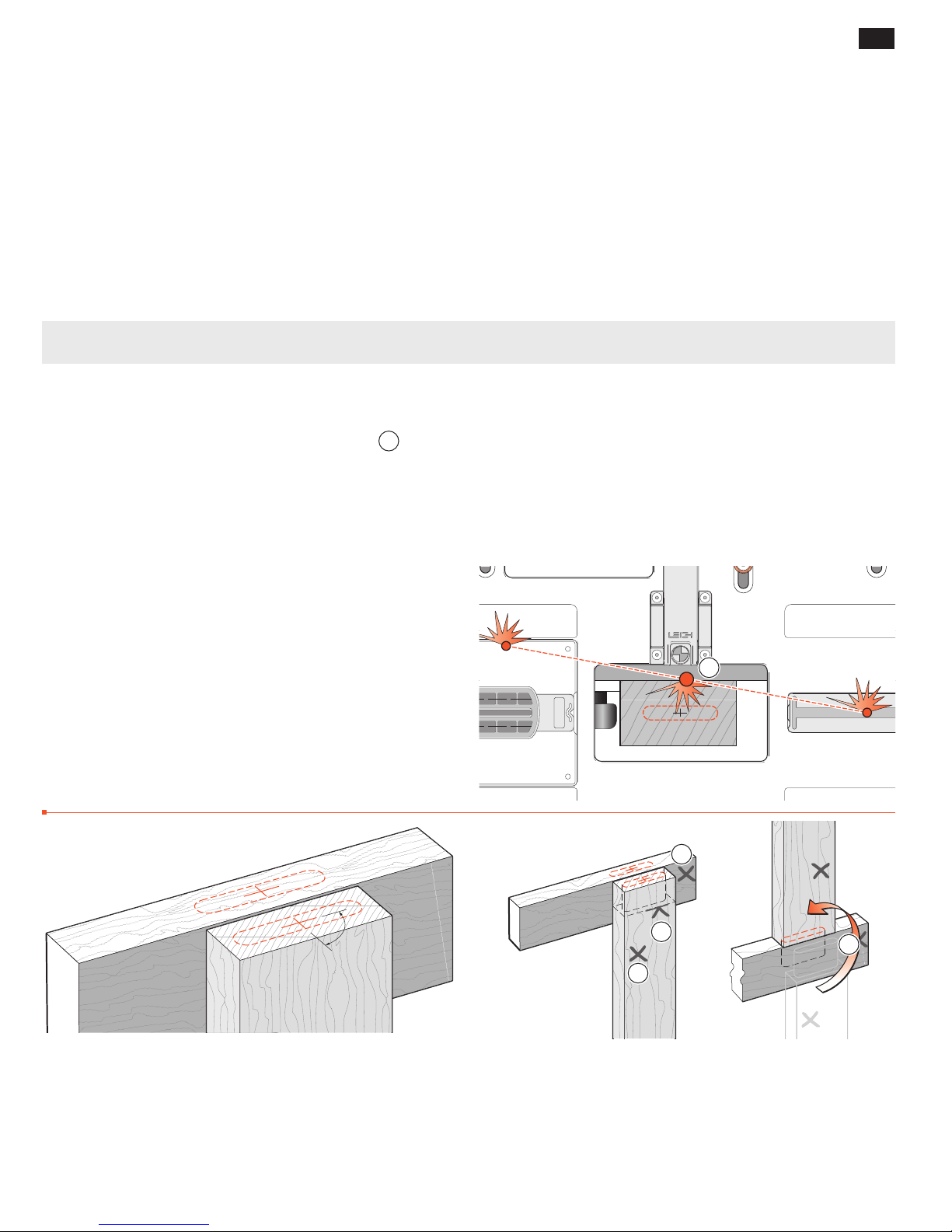
4-1 Let’s make a plain single mortise and tenon. Using a fine pencil,
mark a cross at the center of the required tenon and mortise. The
cross lines along and across the axis lines of the joint must be at
90˚ to each other. Mark the mortise several inches[10cm] or so
away from the end.
1
2
1
3
4-2 In almost all cases, it is critical to have the same side of
workpieces reference against the clamp plate for each tenon and
mortise. So mark one side of each workpiece to reference “this side
toward the clamp plate”
mark
to the required shoulder depth on the tenon workpiece. When
➁
the joint is cut, the tenon piece is rotated 180˚ to assemble
, or “away from” if you prefer. Make a pencil
➀
.
➂
Page 26
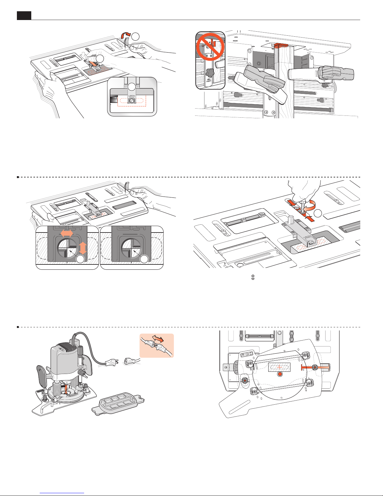
22
2
1
FB
Chapter 4 Frame Mortise & Tenon Jig User Guide
2
1
3
MORTISE & TENON ROUTING PROCEDURES
4-3 If you have not yet mounted the side stop fence, do so now
(see 3-13 to 3-15). Place it off center by about half the width of the
tenon piece; either side, it doesn’t matter. Pull the table sight forward
to its stop
tion the sight over the approximate tenon piece position
. Release the table clamp ➁ and move the table to posi-
➀
. Lock
➂
the table. Always lock the table before positioning workpieces.
4-5 Release the table clamp and move the table until the sight opening is positioned equally around the cross lines on the workpiece. Lock
the table. Because the human eye excels at comparisons, differences
as small as 0.004" can be perceived in the space between the edges of
the line and the triangles as shown here
sight using slight table movements until the spaces appear the same
. You can readily center the
➀
➁
4-4 Clamp the tenon piece with the end edge lightly touching
the underside of the sight. Its side edge should touch the previ-
ously set side stop fence, with the marked side toward the clamp
plate.
1
4-6 Unlock the two
they touch the Stop Post and tighten both stops
front/back limit stops. Move both so
. This prevents
➀
front-to-back movement of the table when later sighting the mortise. Retract the sight.
.
4-7 Unplug the router. Insert the selected guide to the guide
recess and matching diameter bit to the router.
4-8 Make sure the two guide pins are turned up two full turns
from the lowest position!
Place the router on the jig table, the right hand guide pin in the
right side track, the left hand guide pin in the near side of the
guide recess.
Page 27
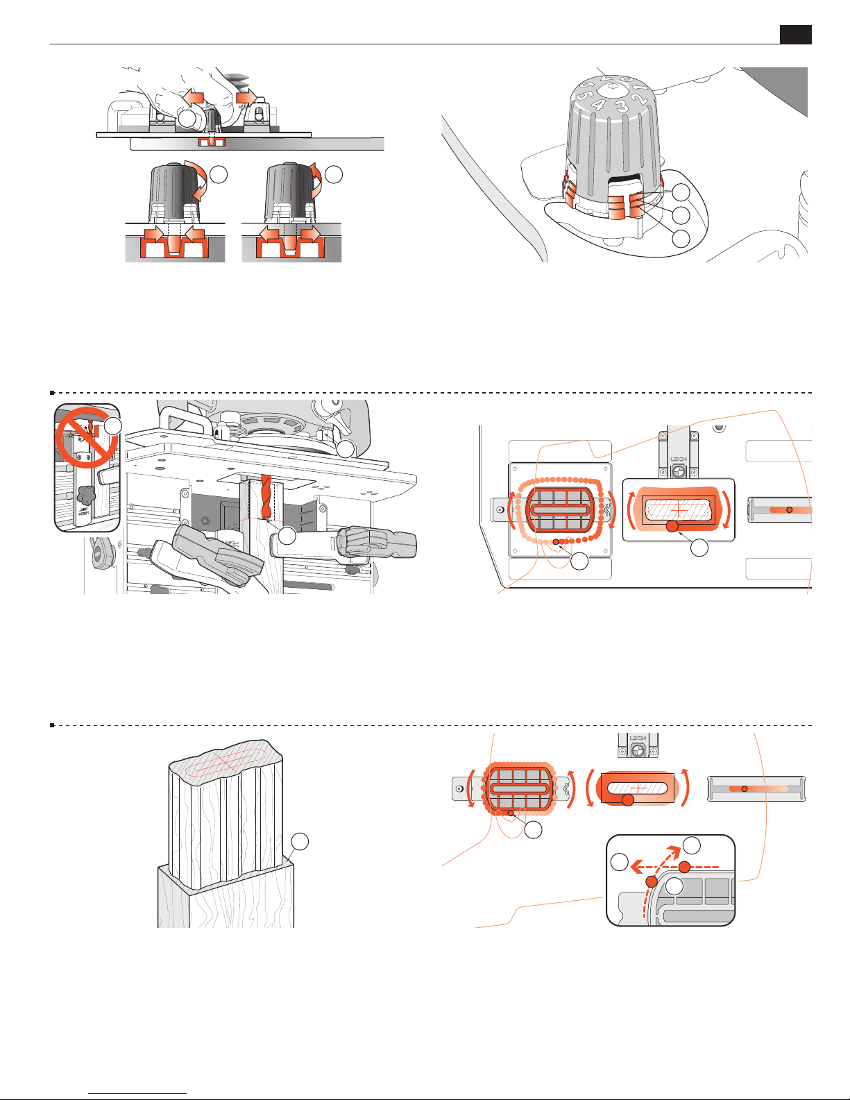
MORTISE & TENON ROUTING PROCEDURES
1
2 3
Chapter 4Frame Mortise & Tenon Jig User Guide
3
2
1
23
4-9 Adjust the right hand guide pin. Grip the right hand pin knob and
move the Sub-Base back and forth to feel the “free play” of the pin across the
slot width
diminish
slightest play can be felt
. Turn the knob down 1⁄8 of a turn at a time, to feel the “play”
➀
. When the “play” stops, turn the knob up 1⁄8 of a turn until the
➁
. The router/Sub-Base should slide freely left to
➂
right. If the right pin is a little “sticky”, turn it up a bit more.
3
2
1
4-11 Plunge the router so the tip of the bit is level with the pencil
mark of the tenon shoulder and lock the plunge
depth stop rod to its stop
. Generally, tenons are routed in one depth
➁
. Set the plunge
➀
setting, it is not necessary to make multiple passes at different depths of
m WARNING: Never rout tenons with the sidestop fence
cut.
in the inverted position
➂
.
4-10 Check that the left hand knob is two turns up. From this
setting the actual fit setting will be established by trial and error
and the result recorded for each guide/bit combination.
Note: The “steps” in the height “washer” indicate numbers of “turns
up”; one turn
two turns ➁ three turns
➀
➂
Never turn the knobs up more than 31⁄2 turns in use.
2
1
4-12 Read all of the next three instructions before routing.
With the guide pin in the near side of the guide recess, switch on the
router power and with firm control, move it in until the bit lightly touches
the tenon workpiece. Very carefully, with the bit very lightly engaging the
wood surface, “climb rout” clockwise around the tenon piece
very light bit contact. Do not run the guide pin on the guide yet
. Maintain
➀
➁
.
4-13 Control the router firmly, the router is driven clockwise
by the bit rotation. This first shallow climb cut will leave a small
but clean shoulder
➀
.
1
1
3
3
2
4-14 Routing counter-clockwise, run the guide pin around the tenon
guide surface. Make sure the pin contacts the entire outer surface
➀
.
In these first test cuts, check the tenon for a completely smooth cut
before removing the piece from the jig. Until you are confident with
this procedure, we recommend as a final clean-up, you run the guide
pin “off” of each guide “corner”
in both directions ➂.
➁
Page 28
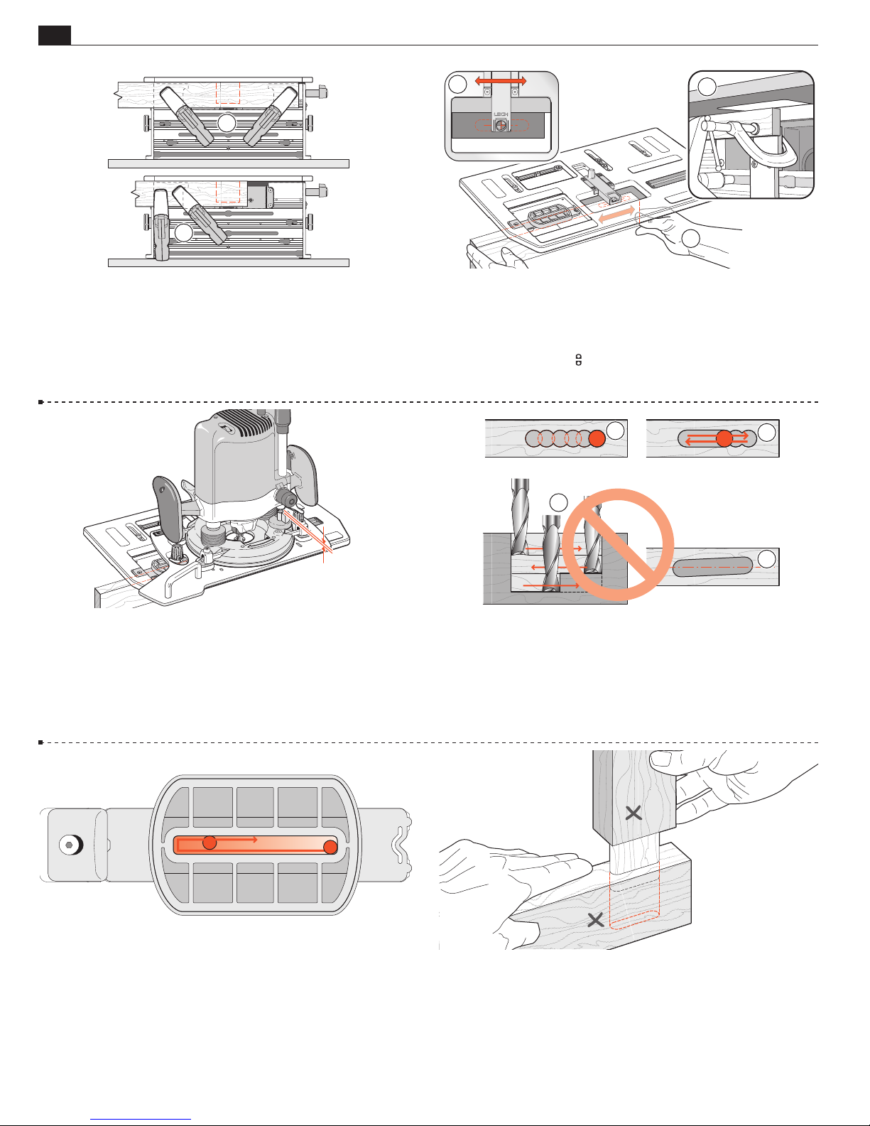
24
FB
3
Chapter 4 Frame Mortise & Tenon Jig User Guide
1
MORTISE & TENON ROUTING PROCEDURES
2
2
4-15 Remove the router and tenon workpiece from the jig. Position
the two clamps so the mortise piece can be positioned for secure holding.
Clamp to either both sides of the vacuum box
Note: Leaving a “horn” on the ends of mortise pieces as in
or to one side ➁.
➀
➀
not only
makes for easy clamping, it’s good woodworking practice as the horns
will be an aid in assembly gluing and clamping later.
4-17
Place the router/Sub-Base assembly on the jig, the left
hand guide pin in the mortise slot part of the guide. Now raise
1
the plunge stop rod slightly, say
⁄32-1⁄16"[1-1,5mm] to allow the
mortise to be routed slightly deeper than the tenon to ensure
perfect tenon shoulder flushness on the finished joint.
1
4-16 Extend the sight. With the marked side of the mortise piece
toward the clamp plate, either move the board left and right
➀
to align the cross with the sight and clamp in place; or clamp in
place first and move the table to align the sight
you previously set the
movement. For routing very small pieces
3
limit stops to allow only left/right
, see 3-16.
➂
1
. Remember,
➁
2
4
4-18 The best way to rout mortises (parallel to workpiece) is
plunge full depth, slightly overlapping holes
left-right-left at full depth of cut
. Do not rout left-right-left at
➁
progressively greater depths without plunging holes
, then clean out
➀
… the bit’s
➂
rotation will pull the bit off the intended mortise line with each
and the mortise may not be parallel to the workpiece.
pass
➃
4-19 Make sure the guide pin is run clockwise against both the
front and rear of the mortise guide slot on the final passes. The
gap between pin and mortise guide slot is greatly exaggerated in
this illustration.
4-20 Remove the mortise piece and test the tenon for fit and
(keeping the marked faces adjacent) for flushness. If the face sides
are not flush, check the straightness of the two parts. If they are
straight, the clamp plate may not be vertically parallel to the bit.
See Appendix II, Jig Adjustments, A2-1 through A2-3.
Page 29
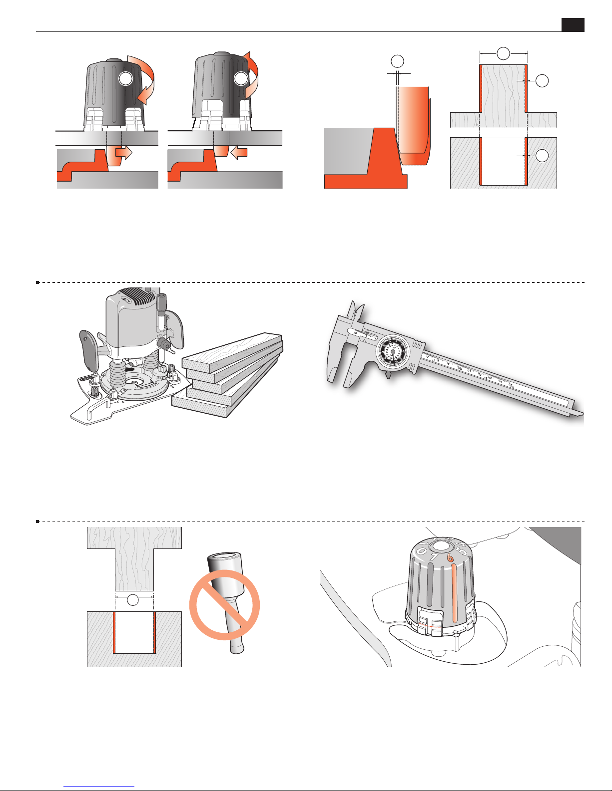
MORTISE & TENON ROUTING PROCEDURES
Chapter 4Frame Mortise & Tenon Jig User Guide
25
21
4-21
If the joint is too loose, turn the guide pin down ➀. If
the joint is too tight, turn the guide pin up
. For how much,
➁
see 4-22. Rout a complete new joint. Note: It’s possible to adjust the
guide pin and rout only one new mortise or tenon part and get a good fit,
but on a project this would mean routing each part at different settings.
Establish ideal pin height for both mortise and tenon at one pin setting.
1
1
2
3
4-22 How much adjustment is required? One eighth of a
turn of the guidepin knob will change the joint glue-line fit by
0.001"[0,025mm]
the tenon thickness by 0.001"[0,025mm] (half of that per side
and increase the mortise width by the same amount
, i.e. turn one-eighth up; the bit will reduce
➀
.
➂
➁
Dimensions and angles shown here are exaggerated.
)
4-23 The FMT Pro can provide this accuracy for settings but
remember, you’re working with wood and a hand-held router,
with lots of movement tolerances; it’s not a computer-controlled
milling machine. Nevertheless, the FMT Pro will allow you to do
very precise and consistent work.
1
4-25 Generally we have found the best fit differential to be
0.005"[0,13mm] “loose”. Basically, the dry joint should “push”
together fairly easily, but not fall apart under its own weight. If a
mallet is needed, it’s too tight.
4-24 If you have a dial or digital calliper (every shop should have
one) you can literally measure the tenon and mortise and adjust
accordingly.
Every 0.002"[0,05mm] of difference in mortise to tenon size (that’s
.001"[0,025mm] on the glue line) should require one eighth of a
turn; down to tighten, up to loosen.
4-26 Once you have established the guide pin setting for a specific
bit/guide combination, record the setting.
5
For example:
⁄16"x11⁄2"[8x35mm] “up 13⁄4 turns”. Using the same
bit and guide next time, use the recorded setting for a good fit
first time. Note: As with all joinery, different wood species do not
necessarily rout precisely to the same fit.
■
Page 30
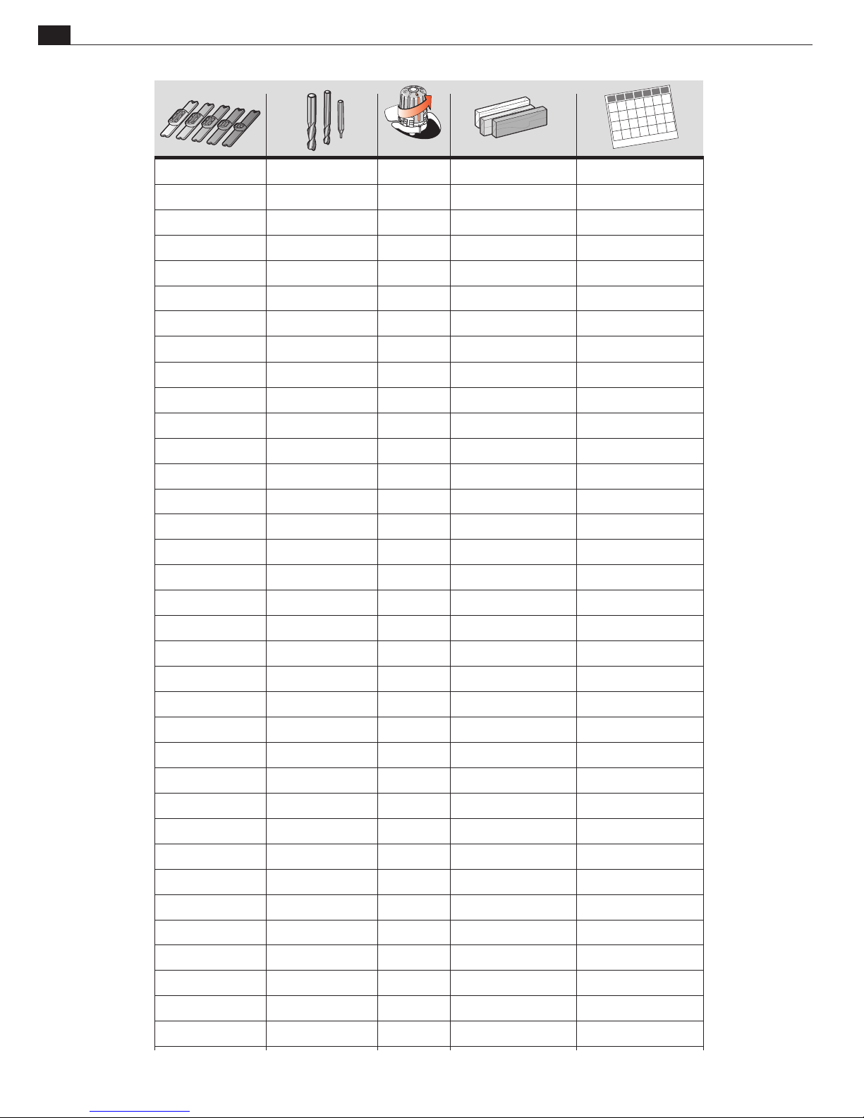
26
TURNS UP SPECIES DATE
Chapter 4 Frame Mortise & Tenon Jig User Guide
Settings Record
TURNS UP SPECIES DATE
e.g. 1/2x2 1/2 1-7/8 cherry 01/01/2017
e.g. 10x40mm 10mm 1-3/8 mahogany Jan.1, 2017
MORTISE & TENON ROUTING PROCEDURES
Hint: Photocopy or scan this page for future records.
Page 31
LR
FB
MORTISE & TENON ROUTING PROCEDURES
Production Procedures
Chapter 4Frame Mortise & Tenon Jig User Guide
2
27
1
1
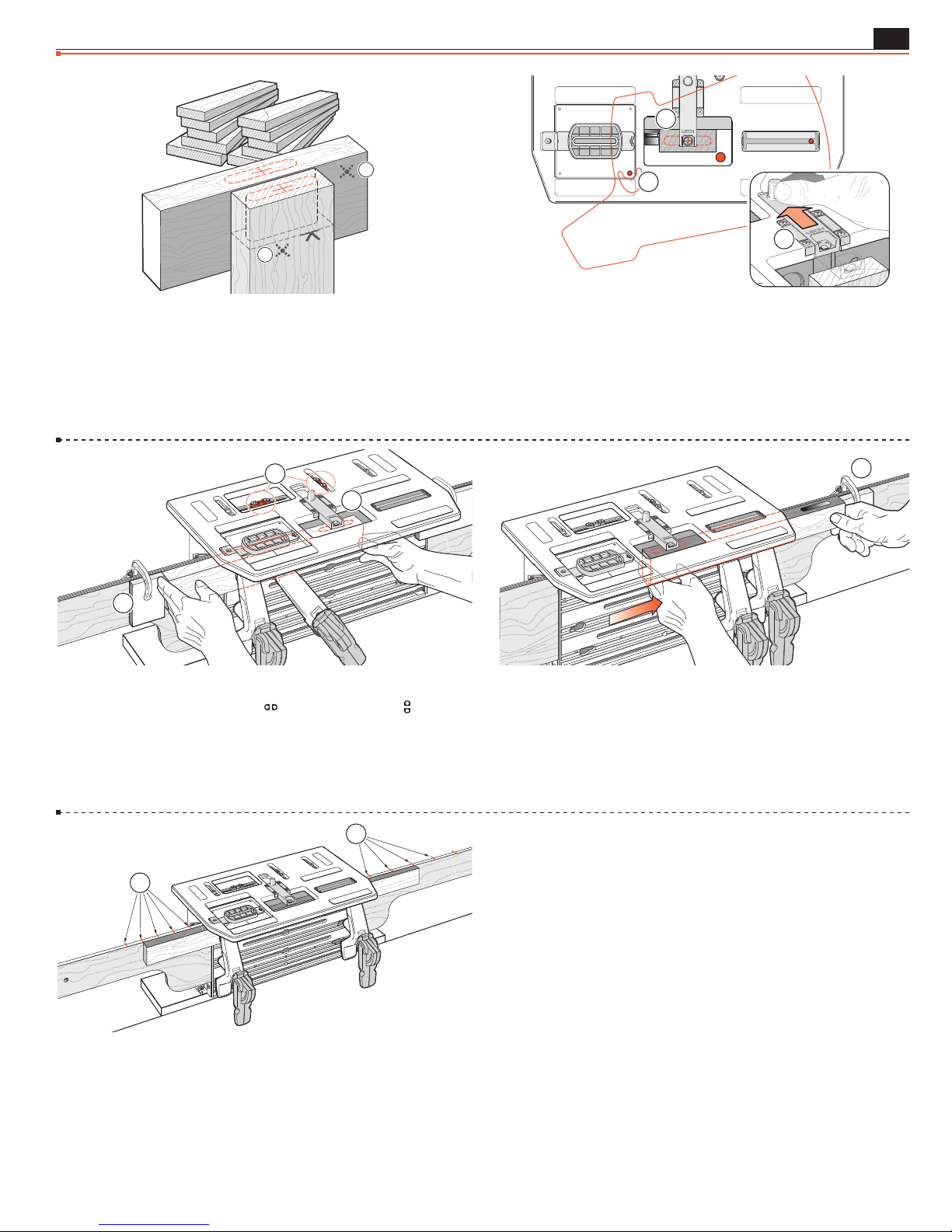
4-27 Production Procedures When routing frame joints it
is only necessary to mark and sight a single tenon and perhaps two
mortises. Once the side stop fence or outriggers are set and the table
sighted for one joint, any number of similar joints may be routed
without marking and without removing the router from the jig.
We recommend marking the finished face which goes against the
clamp plate (shown here from operator view)
3
2
➀
1
.
1
3
4-28 Tenons The router is “parked” with the guide pin in near
front corner of recess
. Extend sight and use only as a tenon stop ➁ when
➀
clamping successive (unmarked) tenon pieces against side stop. Retract
and rout any number of tenons without removing router. Note:
sight
➂
If you forget to retract the sight, the Sub-Base will push it out of the
way as you move it rearward, but we do not recommend this.
2
4-29 Mortises: Sight one mortise ➀ and set a stop block at the
end of the mortise board
➁
. Set
stops to prevent unintentional table movement
1
limit stops and
.
➂
1
limit
4-31 Successive mortises in “ladder” type construction are quick to
rout. Mark all mortises on only one piece (only one needs a front-toback mark!). Sight the first mortise (cross) to set the table and mark
the top of one outrigger in line with the workpiece end. Table locked,
move the workpiece, sighting each successive mortise line, marking
the outrigger(s). To rout, align the unmarked board ends with the
outrigger marks
➀
.
■
4-30 Sight the second mortise by moving the mortise piece (not
the table) and set the second stop block
➁
.
Rout any number of successive (unmarked) mortises without
removing the router from the table.
See next page for Production routing of Small Joints.
Page 32
28
1/4" (6mm) Mortise & Tenon Joints Using a Two Bit Combination
1/8" (3mm) Mortise & Tenon Joints Using Two Bit Combination
Chapter 4 Frame Mortise & Tenon Jig User Guide
Production Procedures for Small Joints
MORTISE & TENON ROUTING PROCEDURES
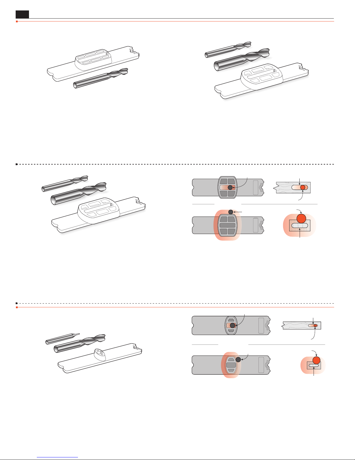
4-32 The FMT Pro is designed so that both mortise and tenon of
a particular-sized joint may be routed with the same sized bit. So
1
if you are making say, a single frame with a
⁄4"[6mm] guide and
bit, this works very effectively. However, it is much more efficient
to rout small tenons with a larger bit, and particularly useful for
production routing. This involves using two bits instead of one.
1/4" (6mm) mortise bit
1/2"(12mm) tenon bit
3/8" (9mm) guide
4-34 Example: 1/4" (6mm) Mortise & Tenon Joints with a
3/8" (9mm) Guide
Using the two bits and guide shown above,
you can rout a 1/4" (6mm) mortise and tenon. The resulting joint
is 1/8" (3mm) smaller than the 3/8" (9mm) guide size. Note:
Any two bit diameters that add up to twice the guide size will
produce a joint size of the smaller bit.
4-33 Two Bit Combination If you want to rout many
1
⁄4"[6mm] mortises and tenons, the tenons can be routed much
1
more quickly with a
⁄2"[12mm] bit*. The Guide and Bit Selection
charts in Appendix I show how different bit combinations can
crank out such extraordinary joints just as quickly and precisely
as larger ones, and with adjustable joint tightness.
*Note: The maximum bit diameter used on the FMT Pro is 1/2"(12mm).
3/8" Guide (9mm)
Guide Pin
Guide Pin
3
/8
x 1
1/4" Mortise Bit (6mm)
1/2" Tenon Bit (12mm)
3
/8
x 1
Mortise
Tenon
4-35 For example:
3/8" guide x 2 = 3/4"
1/4" mortise bit + 1/2" tenon bit = 3/4"
(9mm guide x 2 = 18mm)
(6mm mortise bit + 12mm tenon bit = 18mm)
Routing Joints Smaller than 1/4"
1/8" (3mm) mortise bit
3/ 8" (9mm) tenon bit
4-36
Example: 1/8" (3mm) Mortise & Tenon Joints with a
1/4" (6mm) Guide
Using the two bits and guide shown above,
1/4" (6mm) guide
you can rout a 1/8" (3mm) mortise and tenon. The resulting joint
is 1/8" (3mm) smaller than the 1/4" guide size. Note: Any two
bit diameters that add up to twice the guide size will produce
a joint size of the smaller bit.
Guide Pin
1
/4
x
1
/2
1/4" Guide (6mm)
Guide Pin
1/8" Mortise Bit (3mm)
3/8" Tenon Bit
1
/4
x
1
/2
4-37 For example:
1/4" guide x 2 = 1/2"
1/8" mortise bit + 3/8" tenon bit = 1/2"
(6mm guide x 2 = 12mm)
(3mm mortise bit + 9mm tenon bit = 12mm)
Mortise
(9mm)
Tenon
Page 33
MORTISE & TENON ROUTING PROCEDURES
Chapter 4Frame Mortise & Tenon Jig User Guide
1
29
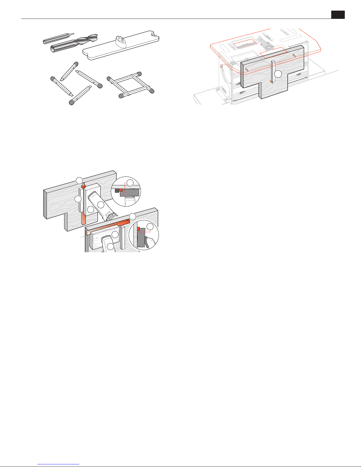
4-38 The tiny 1⁄32" x 3⁄32"[0,8 x 2,4mm] mortises and tenons on this
1
“match frame” were formed (with machine tool bits) on a
15
guide. The
smaller than
⁄32" tenon bit is 7⁄32" larger than 1⁄4". The 1⁄32" bit is 7⁄32"
1
⁄4". A similar metric set: 6mm guide; 1mm mortise bit,
⁄4"x 5⁄16"
and 11mm tenon bit to produce 1mm joints. Machine tool bits as
1
small as 0.010" with
⁄4" shanks and similar metric are available from
machine tool suppliers.
2
1
4
3
4
5
6
9
7
4-40 To hold very small workpieces ➁, make up a rabbeted
holder
thickness, leaving a gap at
Tenon Piece
Piece
with the rabbet slightly shallower than the workpiece
➂
and ➈. i.e. For Tenons: Side stop ➀
➄
Holder ➂ Clamp ➃ Gap ➄. For Mortises: Mortise
➁
, Holder ➆, Clamp ➃, Gap ➈.
➅
■
4-39 For very small joints we recommend attaching a rigid piece
3
of ply or MDF minimum
⁄4"[20mm] to the clamp plate, using
the through screw holes in the plate. This should have its own
mini side stop fence attached for tenons
➀
.
Page 34

30
Chapter 4 Frame Mortise & Tenon Jig User Guide
MORTISE & TENON ROUTING PROCEDURES
Page 35
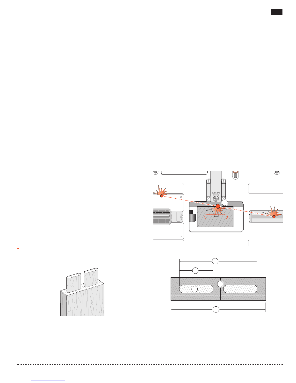
MORTISE & TENON ROUTING PROCEDURES
31
FMT PRO CHAPTER 5
Multiple Joints
Double In Line Joints
Twin Joints
Quadruple Joints
Triple Joints
Before using your Leigh FMT Pro you must
have completed all of the preparatory
steps including reading the router safety
recommendations on the previous pages.
If you haven’t done so, it is essential that
you do it now.
Double In Line Joints
m IMPORTANT SAFETY NOTE
Take great care to not “trap” the bit against the side of tenon
. Do not attempt to rout center tenons in rails thicker than
rails
➀
5
/16"[34mm] before referring to 5-39 through 5-44.
1
Without using the table movement as prescribed, the bit would
have to be plunged into the side of the tenon rail causing the bit
to powerfully “drive” the router across the jig. This could be
dangerous and can damage the jig.
1
5-1 These instructions are based on the assumption that the
correct joint tightness and guide pin setting has been established
and that you are thoroughly familiar with the Jig’s use for single
joints.
4
3
1
3
2
5-2 Note: The maximum dimensions for double in line joints
are:
Tenon Workpiece: 15⁄16 x 51⁄2"[34x140mm]
➀➁
Tenon: 1⁄2 x 2"[12x50mm]
➂
Tenons, both Overall: 1⁄2 x 41⁄2"[12x115mm]
➃
Page 36
32
FB
LR
LR
Chapter 5
Frame Mortise & Tenon Jig User Guide
1
2
2
MULTIPLE JOINTS
11
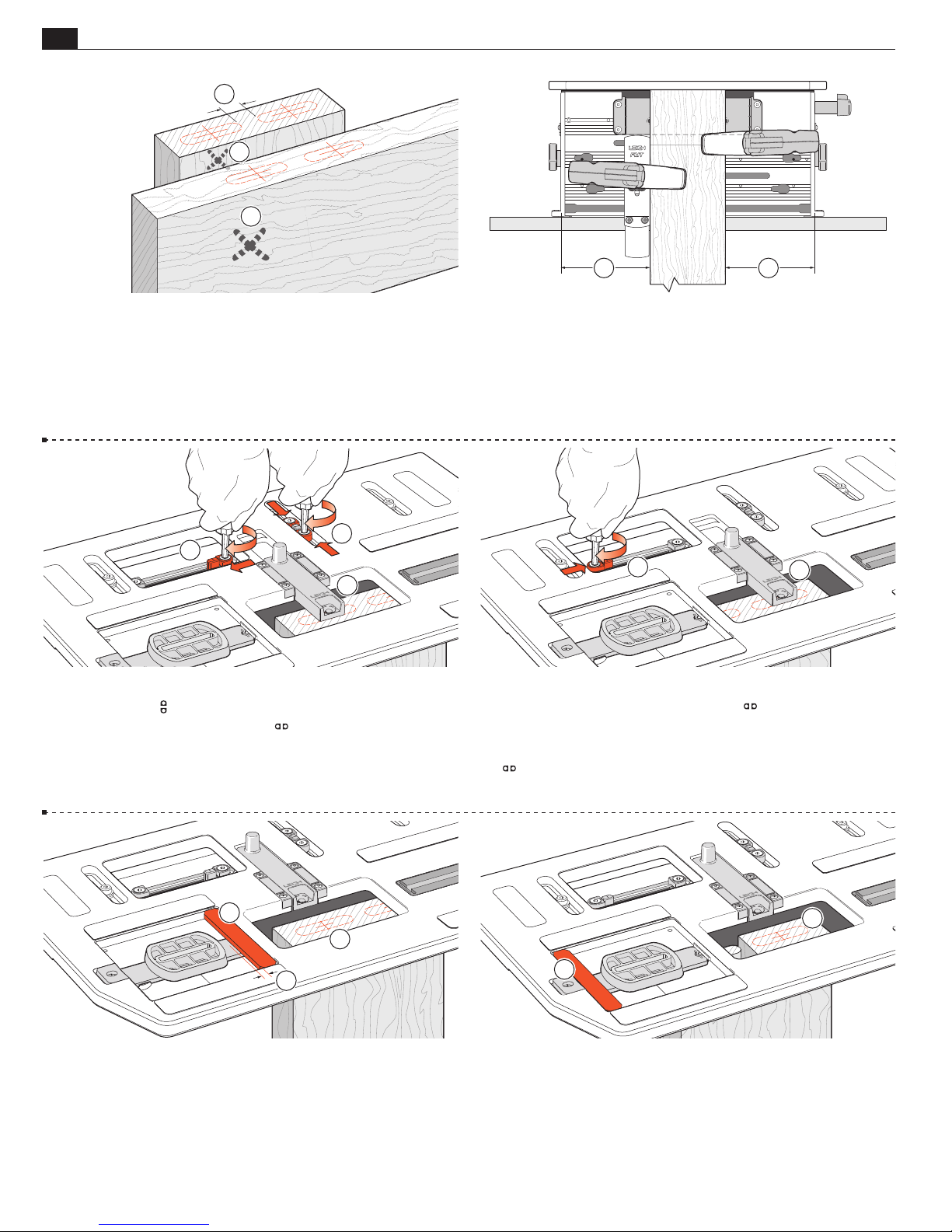
5-3 Mark the two mortise and tenon centers, taking care to allow
space between the joints
Mark the faces that go against the clamp plate
at least equal to the tenon bit diameter.
➀
.
➁
2
3
1
5-5 Sight the left hand tenon and lock the table ➀.
Set and lock both
Set and lock only the right hand
.
post
➂
limit stops against their stop post ➁.
limit stop against its
5-4 Set the sidestop fence so that the tenon piece is clamped
approximately centrally on the clamp plate
5
➀
.
4
5-6 Unlock the table and sight the right-hand tenon ➃ and
lock the table. Set and lock the left hand
the post
➄
.
limit stop against
Release the table clamp and move the table left and right against
the
stops to double-check sight alignment to the two tenons.
Retract the sight.
2
1
3
5-7 Move the table left and lock. Do not rout yet. While with
practise it is fairly easy to avoid routing “into” the right tenon
while routing the left
shop-made “guard” to prevent this
or plywood. Allow a
and guard
. Rout the left tenon.
➂
, we recommend that beginners use a small
➀
. Use 1⁄4"[6mm] thick MDF
3
⁄16"[5mm] gap between the end of the guide
➁
2
1
5-8 Move the table right and lock. Lift the left end of the (stationary) router and move the “tenon guard” left
hand tenon
. Repeat as required for all tenon ends, moving the
➁
. Rout the right
➀
table “guard” piece only once for each pair. Leave the table to the
right. Remove and save the guard. Note: If you change the plunge
height between tenons, there’s the chance of having a step in the
shoulder. We recommend leaving the bit plunged.
Page 37
MULTIPLE JOINTS
Frame Mortise & Tenon Jig User Guide
2
1
Chapter 5
33
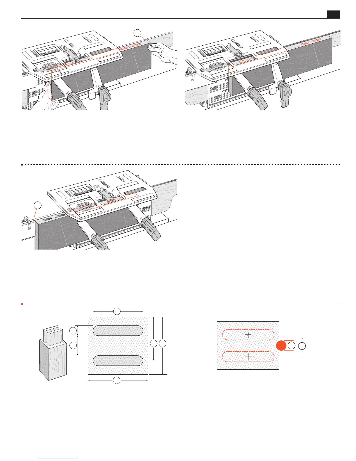
5-9 Extend the sight. Position and clamp the mortise piece so the
right hand mortise of the first pair is centered under the sight
➀
Either mark an outrigger or set a stop block for successive mortise pieces
. Rout the right hand mortise. Note: Outriggers are
➁
referenced in Step 3-19.
1
2
5-11 Extend the sight and unclamp. Sight the left of the other
pair of mortise positions
and re-clamp. To avoid re-sighting each
➀
board, mark the left hand outrigger or set a stop at the workpiece
. Rout the mortise, then move the table and rout the right
end
➁
hand mortise. The table limit stops and outrigger marks (or stops)
are now set for successive workpiece mortising.
■
5-10 Move the table left and lock. Rout the left hand mortise.
.
Leave the table to left.
Twin Joints
3
5
4
2
5-12 Note: The maximum dimensions for twin joints are:
Tenon workpiece: 3" x 31⁄8"+[76x79+mm]
➀ ➁
Tenon size: 1⁄2" x 21⁄2"+[12x65+mm]
➂ ➃
Min. spacing: 9⁄16"[13mm]
➄
Max. distance from board edge to center of tenon: 23⁄8" [60,3mm]
➅
16
2
1
5-13 Mark the two tenon centers taking care to allow space
between the two joints
bit diameter
➁
.
at least slightly greater than the tenon
➀
Page 38
34
FB
LR
FB
Chapter 5
Frame Mortise & Tenon Jig User Guide
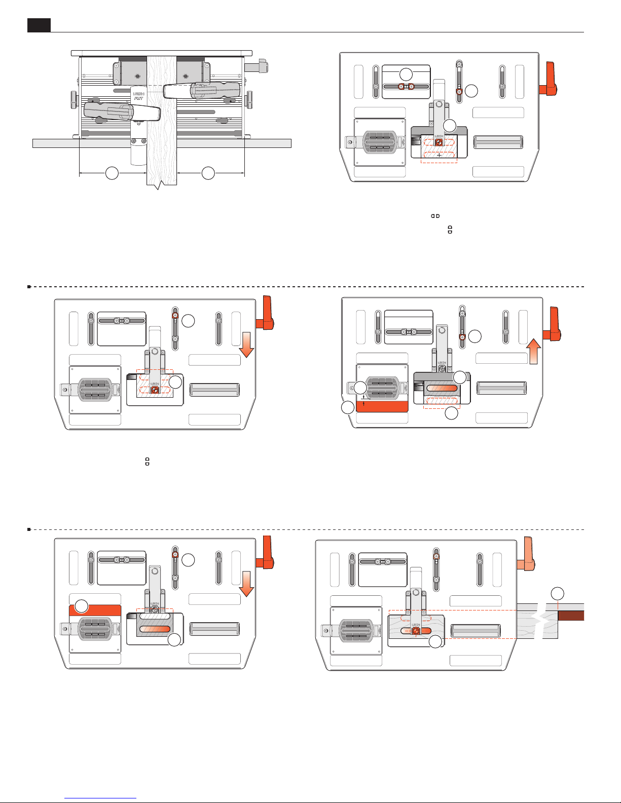
11
MULTIPLE JOINTS
2
3
1
5-14 Approximately center the table left to right and lock ➀.
Extend the sight. Clamp the tenon piece against the sidestop
fence, the tenon piece lightly touching the underside of the sight.
5
4
5-16 Unlock the table and sight the front tenon ➃ and lock the
table. Set and lock the rear
stop against its post ➄. Unlock
the table and move the table front to back against the stops to
double-check the tenon sighting.
5-15 Unlock the table, sight the rear tenon center and lock the
table
post
post
. Set and lock both
➀
. Set and lock the front
➁
.
➂
4
3
limit stops against their stop
limit stop against its stop
1
5
2
5-17 Move the table to the rear against the stop and lock ➀. Do
not rout yet. While with practise it is fairly easy to avoid routing
into the front tenon
beginners use a simple shop-made “guard”
1
⁄4"[6mm] thick MDF or plywood. Allow a 3⁄16"[5mm] gap ➃
between the side of the guide and guard. Rout the rear tenon
while routing the rear, we recommend that
➁
to prevent this. Use
➂
➄
.
1
2
3
5-18 Move the table forward and lock ➀. Lift the left end of the router
and move the “tenon guard” to the rear
. Rout the front tenon ➂.
➁
Repeat as required for all tenon ends, moving the table and guard piece
only once for each pair. Leave the table forward. Note: By using two
or three left-right table positions, (in addition to the front-back positions), the workpiece width and tenon width may be increased to the
maximum (see Chapter 6, Longer and Shorter Joints).
2
1
5-19 Mortises Extend the sight. Position and clamp the mortise
piece so the left end front mortise is centered under the sight
➀
Either mark the right hand outrigger or set a stop block for successive mortise pieces
. Rout the front mortise.
➁
.
Page 39
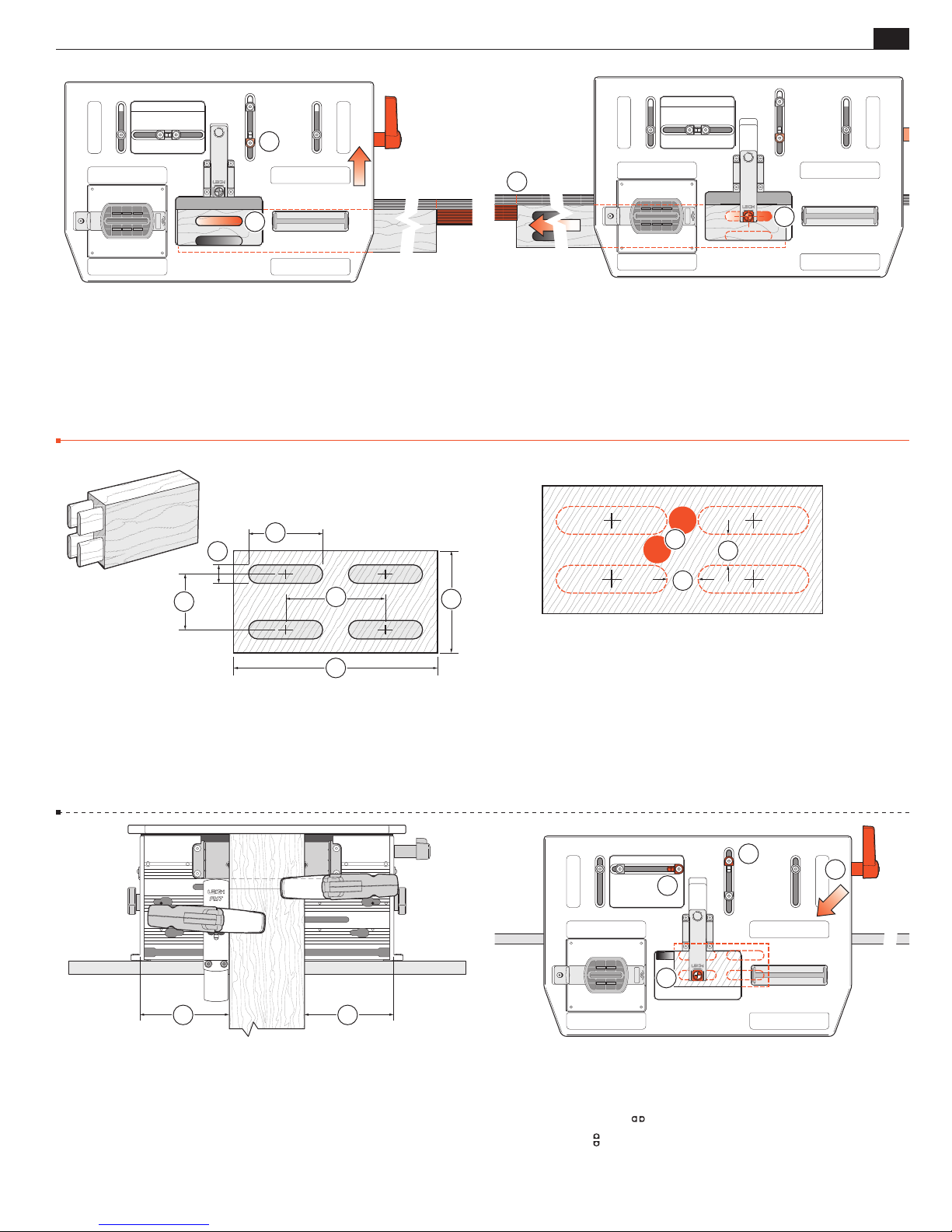
MULTIPLE JOINTS
LR
FB
Frame Mortise & Tenon Jig User Guide
1
2
Chapter 5
35
2
5-20 Move the table back against its stop ➀ and lock. Rout the
rear mortise
Quadruple Joints
. Leave the table back.
➁
2
3
2
3
1
1
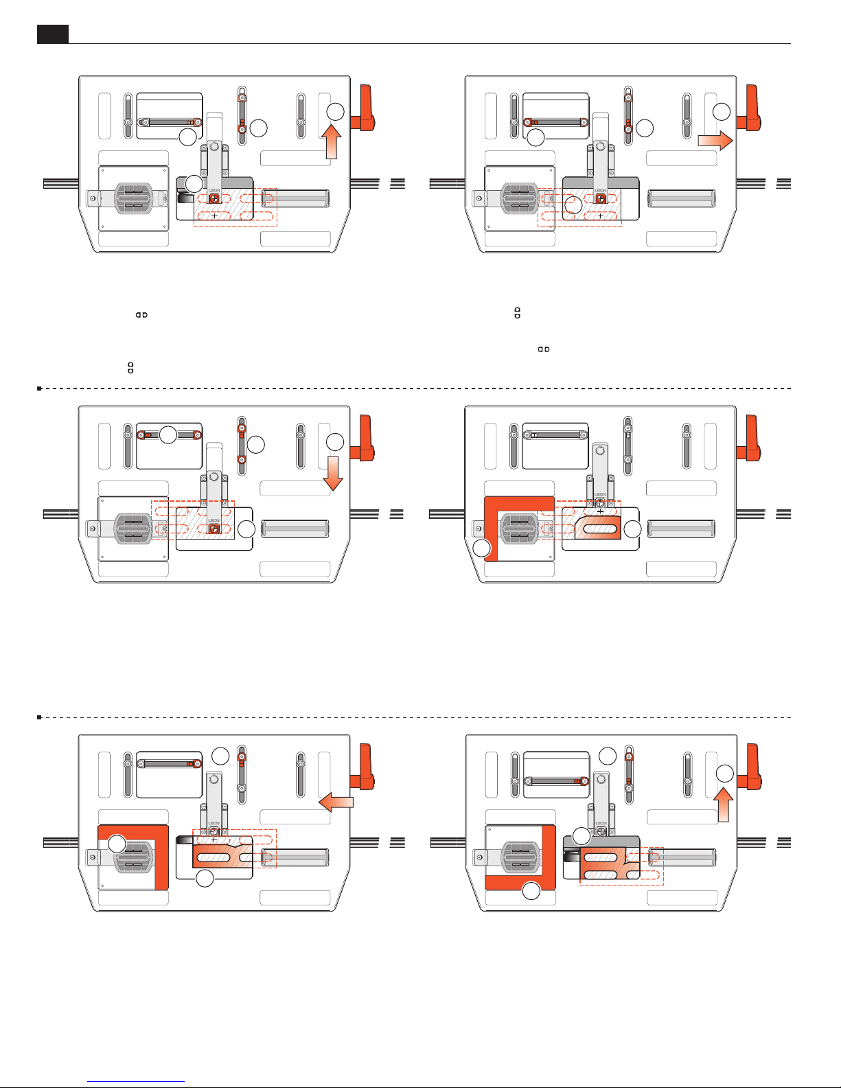
5-21 Extend the sight, unclamp and move the mortise board left
so that the rear mortise of the pair at the right end of the piece
is centered under the sight
outrigger or set a stop
➁
and re-clamp. Mark the left hand
➀
adjacent to that end of the workpiece. Rout
first the rear mortise at this (right-hand) end, then move the table
and rout the front mortise. The outrigger marks or stops are now set
up for successive workpiece mortising.
2
1
■
1
1
5-22 The maximum dimensions for quadruple joints are:
Tenon Workpiece
Tenon Size
➁
Center Spacing
: 3" x 51⁄2"[70 x 140mm]
➀
: 1⁄2 x 2"[12 x 50mm]
: 11⁄2 x 21⁄2"[38 x 63mm].
➂
11
5-24 Center (approximately) ➀ and clamp the tenon board on
the clamp plate and set the side stop fence. Note: If the tenon
board does not touch the underside of the table, extend the sight
to stop the board.
5-23 Tenons Mark the four tenon and mortise centers to suit
your layout. Take care to leave a space between tenons
slightly greater than the tenon bit diameter
2
1
.
➁
3
➀
1
at least
5-25 Extend the sight, release the table clamp and move the table
to sight the left hand front tenon
➀
.
Lock the table.
Move the right hand
Move the back
stop to its post and lock ➁.
stop to its post and lock ➂.
Page 40
36
FB
FB
Chapter 5
Frame Mortise & Tenon Jig User Guide
MULTIPLE JOINTS
5-26
tenon
Release and move the table to sight the rear left-hand
.
➀
Note: Ensure the
.
stop
➁
Lock the table.
Move the front
1
2
1
3
post is still touching the right-hand limit
stop to its post and lock ➂.
1
1
2
1
3
1
2
5-27 Unlock the table and move to the rear right-hand tenon
and sight
Note: ensure the
➀
.
post is still touching the front limit stop ➁.
Lock the table.
Move the left-hand
stop to its post and lock ➂.
2
5-28 All four stops are now set ➀ and provided you have sym-
metrically marked out the joint, moving the table to the front
right-hand tenon, the sight should automatically align with that
mark
. If it does not, do not change anything. Just check the
➁
other three positions; the actual joint will be symmetrical.
1
2
3
2
1
5-29 With practice, it is fairly easy to avoid routing into an adjoining tenon; however, we do recommend that beginners use a simple
“L”-shaped shop made guard to prevent this
3
MDF or plywood and allow a
and guard. Rout the front right tenon
2
⁄16"[5mm] gap between the guide
.
➁
1
3
. Use 1⁄4"[6mm]
➀
1
5-30 Move the table to the front left against the stops and lock ➀.
With the “guard” at the rear-right
, rout the front-left tenon ➂.
➁
5-31 Move the table to the rear left, and lock ➀. Move the “guard”
to the front-right
. Rout the rear-left tenon ➂.
➁
Page 41
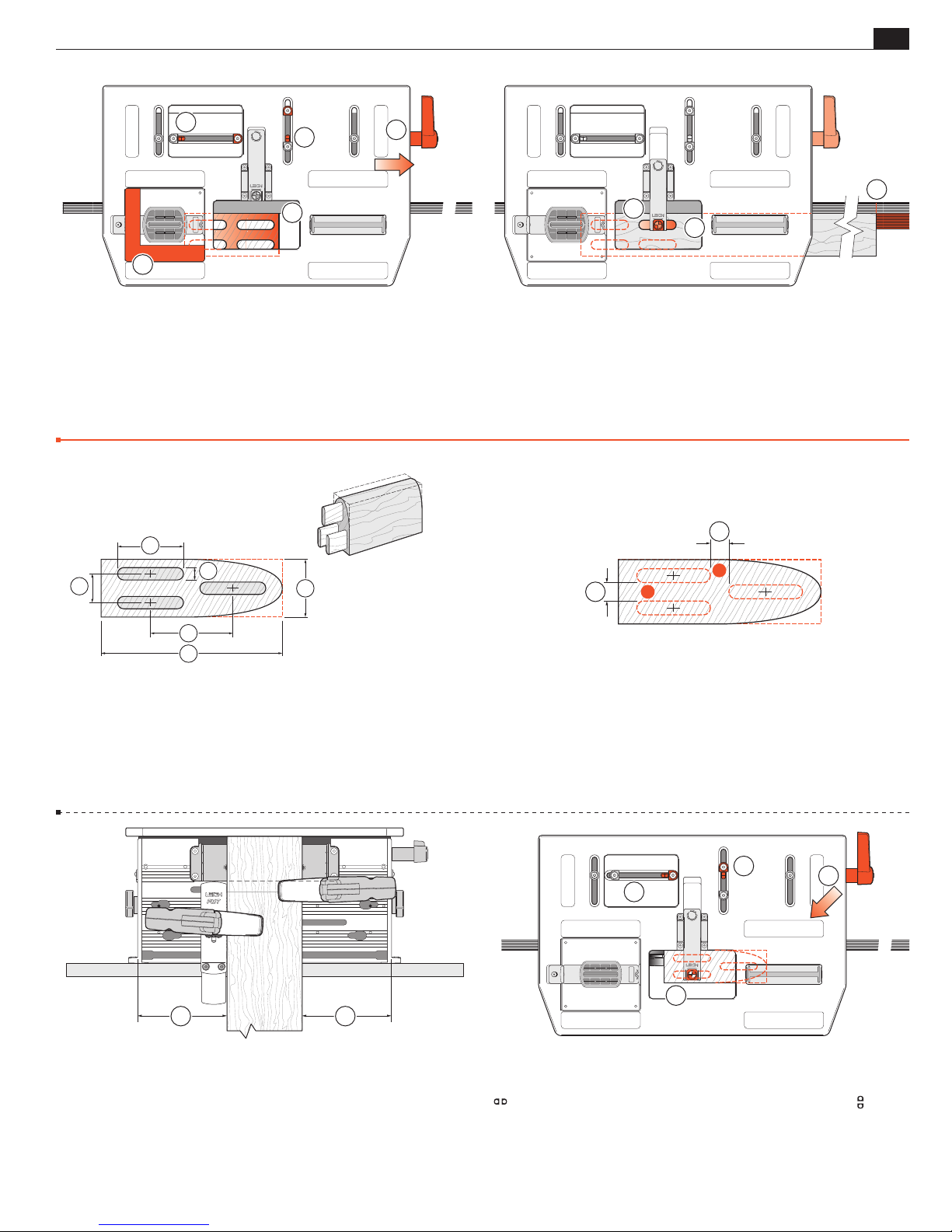
MULTIPLE JOINTS
LR
FB
Frame Mortise & Tenon Jig User Guide
Chapter 5
37
1
1
3
2
1
5-32 Move the table to the rear right against the stops and lock ➀.
Move the “guard” to the front-left
. Rout the rear-right tenon ➂.
➁
Rout all other tenon ends required. Leave the table to the rear-right.
Triple Joints
2
3
2
1
2
3
1
5-33 Mortises Extend the sight, position and clamp the mortise
board so that the rear right mortise is centered under the sight
➀
Either mark an outrigger or set a stop-block for successive mortise
boards
. Rout all four mortises in their respective positions ➂.
➁
Note: The FMT Pro vacuum port may prove ineffective on wide
mortise pieces, particularly on the front mortises.
1
1
■
.
3
1
5-34 Because of safety considerations it is only practical to rout
3
triple joints with
⁄8 bits and guides or smaller.
Maximum dimensions for triple joints are:
Tenon Workpiece
Tenon Size
Center Spacing
: 13⁄4 x 51⁄2"[44 x 140mm]
➀
: 3⁄8 x 2"[10 x 50mm]
➁
: 7⁄8 x 21⁄2"[22 x 63mm].
➂
11
5-36 Tenons Center (approximately) and clamp the tenon
workpiece on the clamp plate
and set the side-stop fence.
➀
5-35
Mark the three tenon and mortise centers, taking care
to leave a space between tenons at least slightly greater than the
tenon bit diameter
5-37
Extend the sight, release the table clamp and sight the
front tenon of the pair
limit stop to the post and lock ➁. Move the back
limit stop to the post and lock
.
➀
3
2
1
. Lock the table, move the right hand
➀
.
➂
1
Page 42
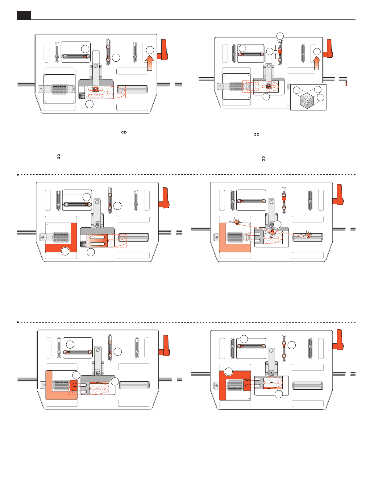
38
LR
FB
LR
FB
Chapter 5
Frame Mortise & Tenon Jig User Guide
MULTIPLE JOINTS
3
2
3
1
1
5-38 Release the table clamp and sight the rear tenon of the
, making sure that the right-hand
pair
➀
.
post
➁
stop is against its
Lock the table.
Move the front
limit stop to its post and lock ➂.
2
2
2
5
5
1
1
3
4
5-39 Release the table clamp and move the table to sight the third
(single) tenon
Set and lock the left-hand
. Lock the table.
➀
limit stop to its post ➁. Cut a small
hardwood block to the following size:
Width
to a snug fit between the rear
1⁄2"[13mm], Depth ➃ 5⁄16"[8mm], Length ➄: Cut to length
➂
limit stop and its stop post. This
block will be used for the “third” tenon position.
1
3
1
5-40 Rout the left pair of tenons in the same way as for the quadruple tenons
and an L-shaped guard
(see 5-30 and 5-31), using the Limit Stops ➁
➀
in the guard recess to prevent accidental
➂
routing of adjacent tenons.
m Do not attempt routing the third tenon before reading on.
1
1
2
5-42 So to reduce the thickness, move the table right and rearward
against the stops
small “guard” piece
as if to rout a quadruple tenon. Then add a
➀
to the L-shaped guard in the guide recess.
➁
Now rout away part of the workpiece
3
.
➂
5-41 m If the tenon rail is thicker than 1
5
⁄16"[34mm] (as is
most likely with this type), then great care must be exercised not
to “trap” the bit
when routing the third tenon.
➀
i.e. The bit would have to be plunged into the side of the tenon
board. This could result in the bit “driving” itself across the board
which could be dangerous.
1
2
1
3
5-43 Move the table forward, keeping it to the right ➀. Flip the
guards to the back
workpiece
➂
.
. Now rout away the front-right part of the
➁
Page 43
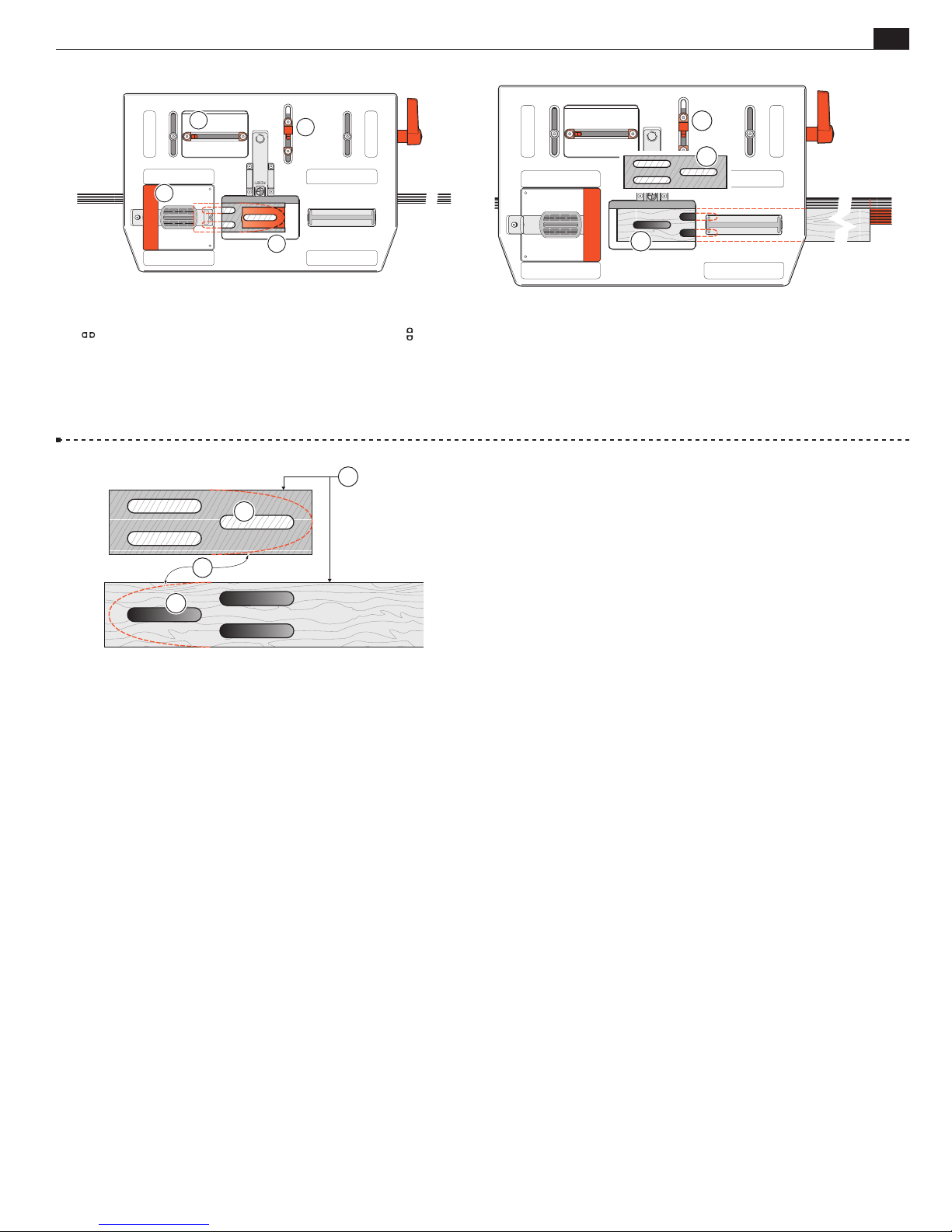
MULTIPLE JOINTS
FB
Frame Mortise & Tenon Jig User Guide
Chapter 5
39
1
2
1
3
5-44 Release the table clamp. With the table to the right, against
the
stop, put the small block between the rear
and its post
. You must always use the same limit stop for all
➀
stop
other third tenons and mortises. Using a guard to avoid routing,
into the other two tenons
, rout the rest of the third tenon ➂.
➁
3
1
4
3
1
2
5-45 m Mortises Triple mortises are routed the opposite way
around. If the single tenon is to the right
must be to the left
the same side of the stop post
, and vice-versa, using the same block on
➁
.
➂
, the single mortise
➀
2
5-46 Remember, mortises are routed the opposite way around to
their matching tenon, e.g. in this illustration the single tenon is to
the right
, single mortise to the left ➁. Keeping the reference faces
➀
together on the finished joint will ensure that the mortises and tenons
will align
not do any shaping of workpieces until after the joints are routed
. It’s much easier to clamp square section workpieces so do
➂
➃
.
■
Page 44

40
Chapter 4 Frame Mortise & Tenon Jig User Guide
Chapter 5
MULTIPLE JOINTS
Page 45
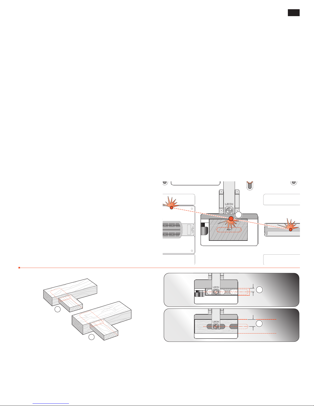
MORTISE & TENON ROUTING PROCEDURES
41
FMT PRO CHAPTER 6
Workpiece and
Joint Options
Different Workpiece Thicknesses
Longer and Shorter Joints
Thicker and Wider Boards
Before using your Leigh FMT Pro you must
have completed all of the preparatory
steps including reading the router safety
recommendations on the previous pages.
If you haven’t done so, it is essential that
you do it now.
m IMPORTANT SAFETY NOTE
Take great care to not “trap” the bit against the side of tenon
. Do not attempt to rout center tenons in rails thicker than
rails
➀
5
/16"[34mm] before referring to 5-39 through 5-44.
1
Without using the table movement as prescribed, the bit would
have to be plunged into the side of the tenon rail causing the bit
to powerfully “drive” the router across the jig. This could be
dangerous and can damage the jig.
1
Different Workpiece Thicknesses
1
2
6-1 So far we have only illustrated joints where the mortise and
tenon workpieces are the same thickness. There will be numerous times when this is not the case, as in where the tenon piece
is thinner and centered on the mortise board
tenon piece is deliberately off-center on the mortise piece
, and where the
➀
➁
1
2
6-2 Single or double (in-line) mortise and tenons are straight
forward. Simply mount and sight and rout all the tenons as shown
before
front-back position before routing
.
, then mount and re-sight the mortises at the desired
➀
.
➁
Page 46
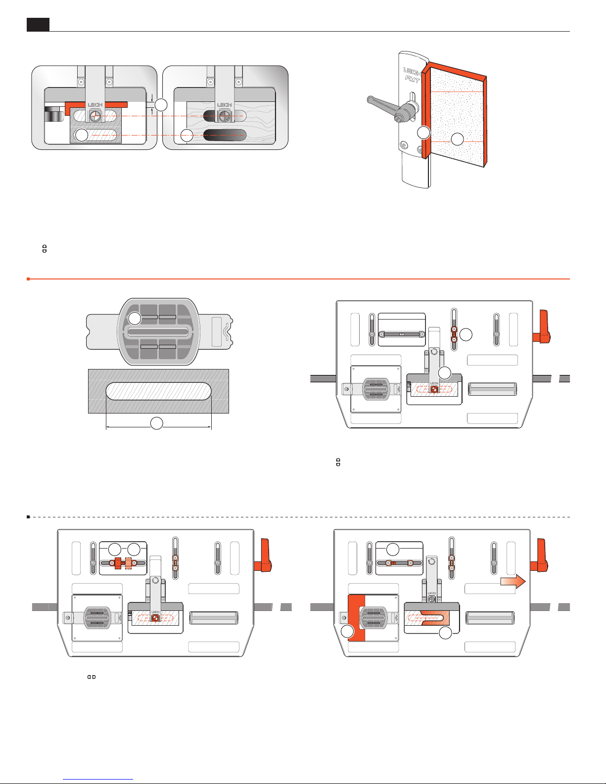
42
FB
FB
Chapter 6
Frame Mortise & Tenon Jig User Guide
3
WORKPIECE AND JOINT OPTIONS
1
2
6-3 Side-by-side double and quadruple joints of different stock
thicknesses require a packing piece (see 6-4) between the clamp plate
and tenon piece, the thickness equal to the offset of the two pieces.
For example, a 2"[50mm] tenon piece
mortise piece
will require a 1⁄2"[12,5mm] packing piece
➁
centered on a 3"[75mm]
➀
. m Never
➂
attempt to achieve this alignment by re-sighting the joint and resetting
the
limit stops. That would make it impossible to guarantee
twin-tenon to mortise alignment.
Longer and Shorter Joints
1
1
2
6-4 This packing piece should include its own side-stop fence ➀
and if required frequently, should have sandpaper glued onto its
outer surface for secure workpiece clamping
➁
.
Sight and rout the tenons in the usual way with the packing piece
in place. Then, remove the packing piece before sighting and
routing the mortises.
■
2
1
2
6-5 The FMT Pro table movement allows for easy routing of oddsized joints. For example, you may want to rout a 3"[75mm] joint
and you only have a 2"[50mm] guide
. Use this simple formula:
➀
➁
Joint, minus Guide, divided by 2.
1
÷ 2 =
Example: 3" - 2"
Cut a small block equal to the result; in this example,
6-7 Set the
between the stops and post
⁄2"[75 - 50 ÷ 2 = 12,5mm]
1
⁄2"[12,5mm].
12
stops one at a time with the small block
. This ensures that the table move-
➀➁
ment is centered about the joint center-mark on the stock. Remove
the block, but save it.
6-6 Tenons Mark the center as before.
Position and sight the tenon
Set the
stops against the post ➁.
3
1
, and lock the table.
➀
2
6-8 To rout the wider tenon:
- Move the table right, to the stop
- Rout the right-hand end of the tenon
➀
.
.
➁
Use a guard in the left end of the guide recess if necessary
➂
.
Page 47
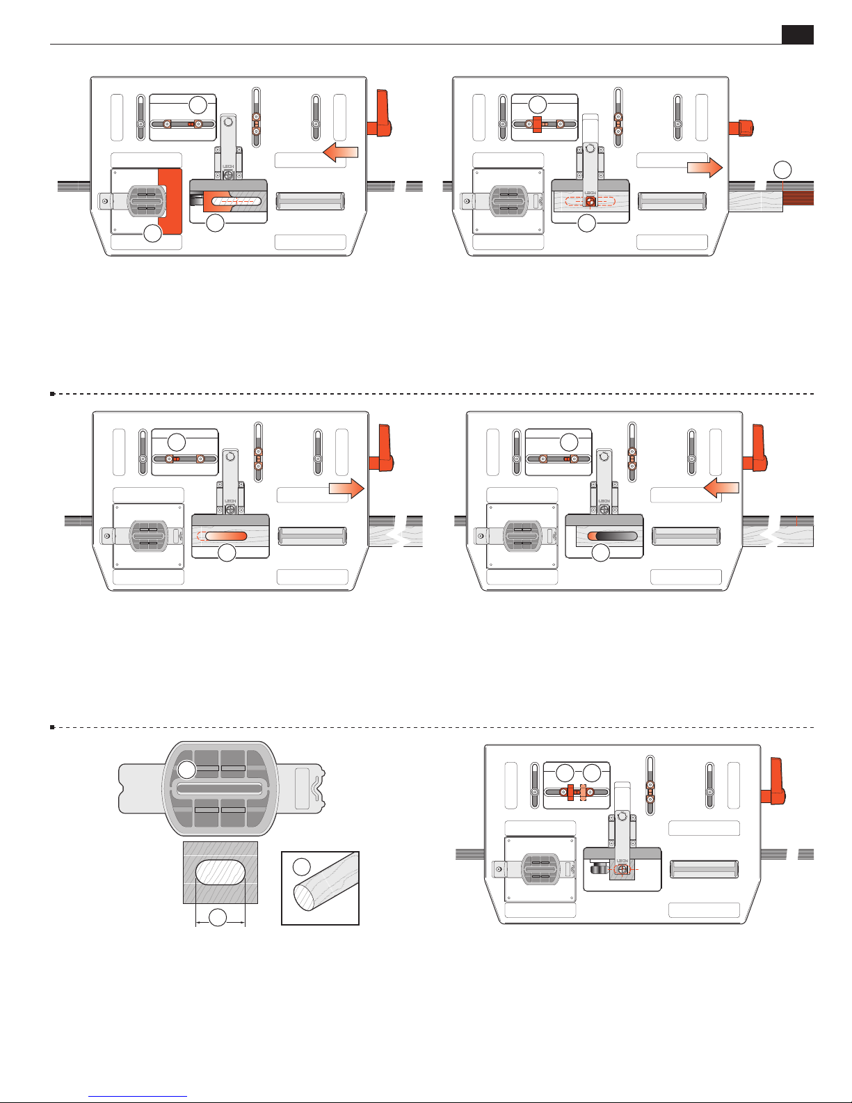
WORKPIECE AND JOINT OPTIONS
Frame Mortise & Tenon Jig User Guide
Chapter 6
43
1
3
2
6-9 - Move the table left to the stop ➀.
- Rout the left-hand end of the tenon
➁
.
If you’re using a “guard”, flip it to the right end of the recess
- Repeat for all required tenons.
1
➂
1
2
6-10 Mortises Release the table clamp. Use the small block
between one stop and the stop post
.
Center a mortise piece under the sight and clamp
blocks or marks on the outriggers
1
and lock the table clamp.
➀
. Set side-stop
➁
.
➂
3
2
6-11 Move the table right to the stop ➀. Rout the right-hand
end of the mortise
, using the full length of the mortise guide.
➁
2
3
1
6-13 For mortises and tenons shorter than the guide, reverse the
calculation: Guide, minus Joint, divided by 2.
Example: you may want a 1"[25mm] joint
1
÷ 2 =
So, 2" - 1"
Make a block
3
⁄16"[5mm] dowel ➂ to act as a guard when routing the mortises.
⁄2 [50mm - 25mm ÷ 2 = 12,5mm].
1
⁄2"[12,5mm]. You will also need a short length of
using 2"[50mm] guide ➁.
➀
2
6-12 Move the table left to its stop ➀. Rout the left-hand end of
the mortise
. Repeat for all required mortises.
➁
So to recap; for joints longer than the guides:
-move the table right and rout right,
-move the table left and rout left.
12
6-14 Tenons Setting the block and limit stops for the shorter
tenons procedure
is exactly the same as for longer tenons
➀➁
setup, except when you come to rout.
Page 48
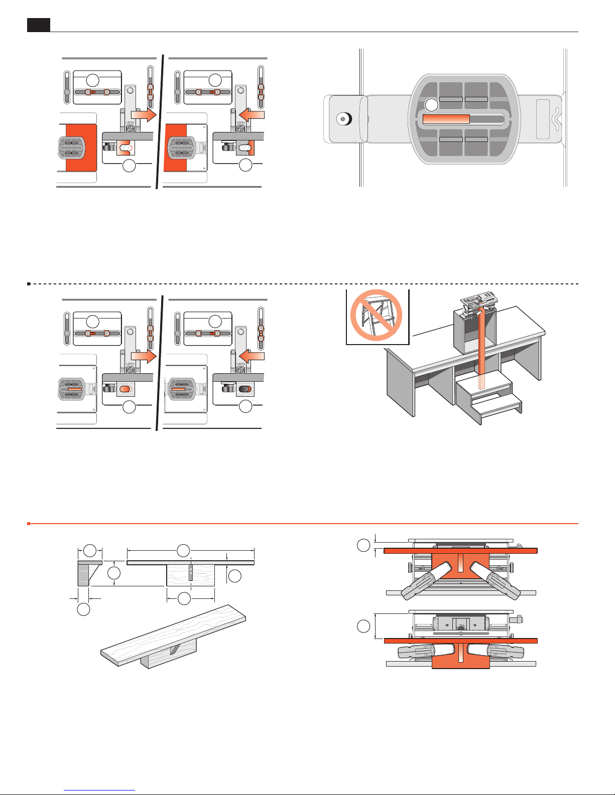
44
Chapter 6
Frame Mortise & Tenon Jig User Guide
WORKPIECE AND JOINT OPTIONS
1
1
6-15 Then it is:
-Move table right; rout to the left
-Move table left; rout to the right
➀
➁
.
.
Again, use a guard in the guide recess if necessary.
1
2
1
2
6-16 Mortises The rule is the same for mortises except you will
3
need to use a small piece of that
guide’s mortise slot
. The dowel should be slightly longer than the
➀
⁄16"[5mm] dowel as a guard in the
difference between the guide length and joint length; in this example,
slightly longer than 1"[25mm]. In this example, the joint is only 1"
long and the guide mortise slot is 2". So you need a guard dowel to
prevent cutting a mortise longer than required.
2
1
2
6-17 So, for the shorter mortises:
➁
➀
.
.
Table right; dowel right; rout left side
Table left; dowel left; rout right side
The length of the dowel guard allows you to rout a mortise slightly
shorter than required in the first cut and to clean out in the second cut.
Thicker and Wider Boards
1
3
5
2
6
4
6-19 Make this bracket to mount and mortise a wide board face,
clamp pieces greater than Leigh Clamp 3" capacity, and center mortises
5
on boards up to 4
41⁄2"[115mm]
➀
24"[600mm]
➁
⁄8"[115mm] wide or even 63⁄8"[162mm].
43⁄4"[120mm]
➂
9"[230mm]
➃
2"[50mm]
➄
3⁄4"[20mm]
➅
6-18 To rout long vertical boards you could build a jig stand to
mount on your bench. Make the stand/bench combination high
enough to accept the desired board length. Bolt securely to the bench.
Make a stable platform as shown here to stand on. Don’t use a
folding step, these are unstable. Other novel solutions: holes in (suspended) floor; jig bolted to deck or mezzanine railing; wall brackets.
1
1
■
6-20 Use the Leigh clamps to secure the bracket to the FMT
Pro clamp face and adjust the distance below the table to slightly
greater than the mortise piece thickness
➀
.
Page 49
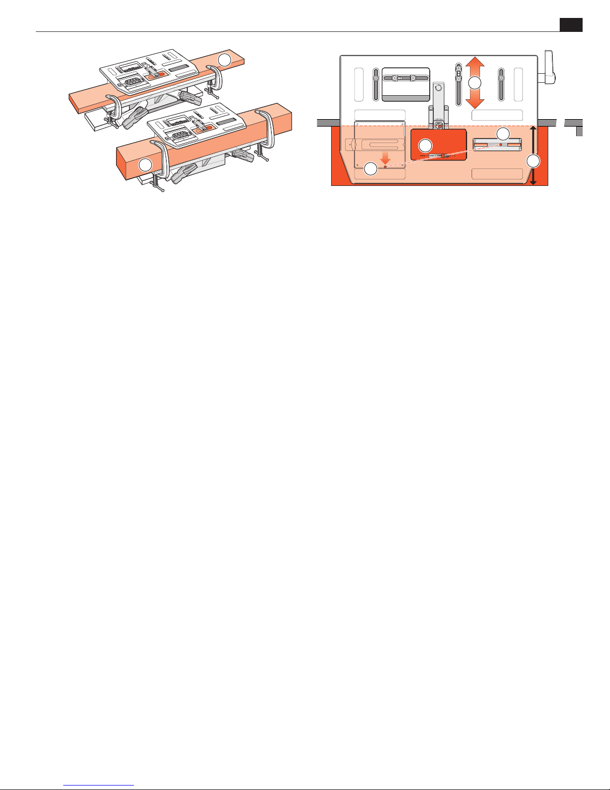
WORKPIECE AND JOINT OPTIONS
2
Frame Mortise & Tenon Jig User Guide
1
4
2
3
Chapter 6
5
1
45
6-21 Use C-clamps to hold the workpiece onto the bracket, with
the workpiece rear edge touching the clamp plate. Now raise the
bracket so the workpiece touches the underside of the table.
Re-secure with the Leigh Clamps. The widest board in which a
5
mortise may be centered is 4
is 4"[100mm]
➁
.
⁄8"[115mm] ➀.The thickest capacity
6-22 Mortises in center of boards 4 5/8
"
to 6 ½
"
[115 to
165mm] ➀: Mark mortise center on a test board ➁. Using the
guide recess front edge as mortise guide
the mortise
in the pin track
. Control mortise length with 3⁄16"[5mm] dowel pieces
➃
(see 6-16). Note: This is not a standard Leigh
➄
solution, but we thought it would solve this rare challenge.
, adjust the table to center
➂
■
Page 50

46
Chapter 4 Frame Mortise & Tenon Jig User Guide
Chapter 6
WORKPIECE AND JOINT OPTIONS
Page 51
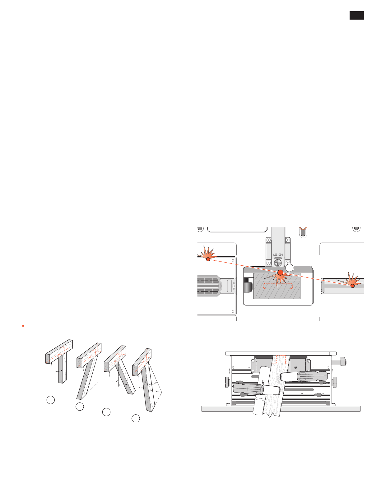
MORTISE & TENON ROUTING PROCEDURES
47
FMT PRO CHAPTER 7
Special Joints
Angled Joints
Through Tenons
Bridle Joints
Asymmetric Tenons
Haunched Joints
Doweling
Before using your Leigh FMT Pro you must
have completed all of the preparatory
steps including reading the router safety
recommendations on the previous pages.
If you haven’t done so, it is essential that
you do it now.
Angled Joints
m IMPORTANT SAFETY NOTE
Take great care to not “trap” the bit against the side of tenon
. Do not attempt to rout center tenons in rails thicker than
rails
➀
5
/16"[34mm] before referring to 5-39 through 5-44.
1
Without using the table movement as prescribed, the bit would
have to be plunged into the side of the tenon rail causing the bit
to powerfully “drive” the router across the jig. This could be
dangerous and can damage the jig.
1
90˚
1
45˚
90˚
10˚
2
3
7-1 The majority of frame joints are at 90˚ ➀ but the ability
to angle joints is essential in, for example, chair construction.
Whether these joints are single angles
angle
they are easily achieved on the FMT Pro.
➃
➁
45˚
4
10˚
and ➂ or a compound
7-2 Angling the sidestop fence gives a single angled joint in
the left-right direction.
Page 52
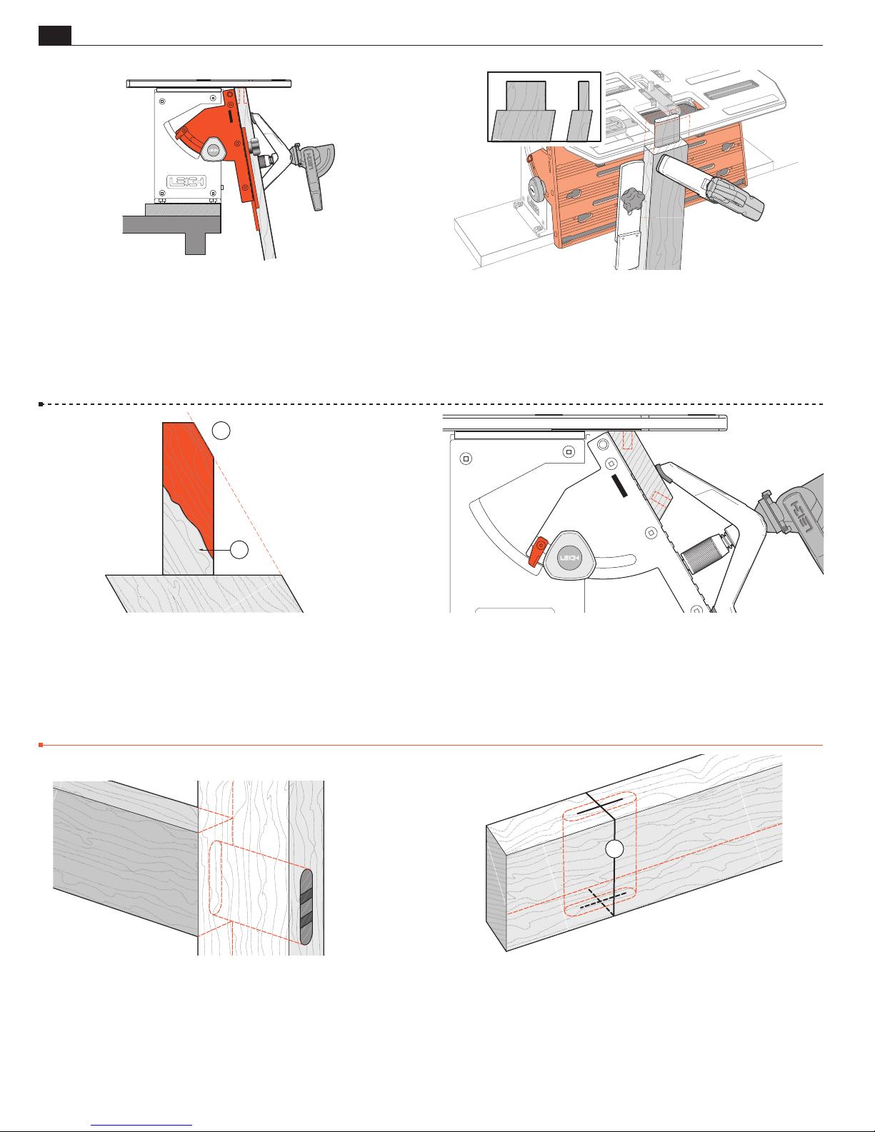
48
Chapter 7
Frame Mortise & Tenon Jig User Guide
SPECIAL JOINTS
7-3 Angling the clamp plate with vertical sidestops also gives
a single angled joint in the front-back direction.
2
1
7-5 The FMT Pro clamp plate can be angled up to 30˚ but it is
doubtful you will ever need to approach even 10˚ on a mortise and
tenon joint. The strength of a tenon across its grain lessens considerably as the angle increases
. In addition, the length and position of
➀
the tenon is limited in slope by the angled workpiece relative to the
vertical bit
(angle demonstrated in this illustration is excessive.)
➁
7-4 Angling both fence and clamp plate give a double, or
compound angled joint.
7-6 However, you may for example, want to machine spline
mortises or dowel holes in a stave type construction in, say, octa-
1
gons at 22
⁄2˚, or hexagons at 30˚, so the 30˚ capacity may prove
to be useful. You can then machine precisely fitting splines on the
FMT Pro and trim them to length.
■
Through Tenons
7-7 Through Tenons Occasionally, a design feature will
call for through, exposed tenons, possibly “wedged” for decorative
effect. The limited depth of cut of router bits can make this difficult,
but the two-sized bit technique described previously, combined
with the precision of the FMT Pro, makes this procedure perfectly
feasible in many instances.
1
7-8
relative to the cutting depth and diameter of the bit.
the left-right part of the joint center mark
The problem with through mortises is their great depth
However, if
is carefully squared
➀
around the mortise workpiece, it is possible to accurately plunge
from both sides.
Page 53
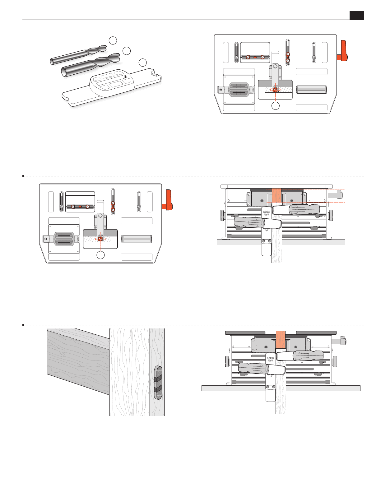
SPECIAL JOINTS
Frame Mortise & Tenon Jig User Guide
1
2
3
1
Chapter 7
49
7-9 Here’s an example.
1
⁄4"[6mm] joint through 11⁄2"[35mm] deep mortise.
1
⁄4"[6mm] bit for mortises ➀.
Select
1
⁄2"[10mm] bit to rout the 11⁄2"[35mm] long tenon ➁.
Select
3
⁄8"[8mm] guide ➂ for length from the guide/bit selection
Select
chart in Appendix I.
2
7-11 Turn the mortise piece end for end and, keeping the same
reference side of the mortise board to the clamp face, carefully
sight the “vertical” mortise center mark
and lock the table .
➁
Plunge and rout to clear the through mortise.
7-10 Carefully sight the mortise taking particular care to center
the “vertical” line
in the sight. Plunge and rout down deeper
➀
than half the mortise board depth.
7-12 Rout the tenons with the larger (longer) bit slightly deeper
than the mortise depth.
7-13 It may even be possible to make tenons long enough to be
raised if this decorative effect is desired. “Wedging” the tenons is a
simple hand procedure and a nice decorative touch.
7-14 If the tenon stock is smaller than the table opening it may
be possible (after sighting) to slide the tenon workpiece up to
1
almost touch the router base and thereby gain an extra
⁄2"[10mm]
of tenon length. Assuming of course that the bit has sufficient
cutting depth.
■
Page 54
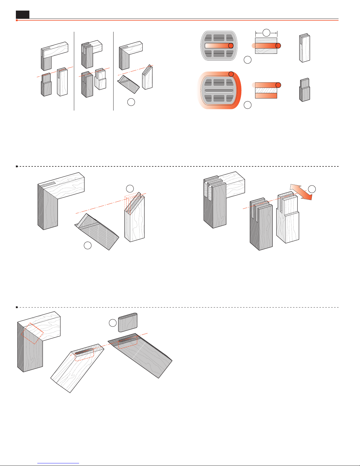
50
Chapter 7
Bridle Joints
Frame Mortise & Tenon Jig User Guide
2
MORTISE
SPECIAL JOINTS
1
1
7-15 Routing bridle joints on the FMT Pro is simple. All the workpieces (with the exception of the mitered tenon)
are mounted
➀
vertically on the jig.
2
1
7-17 The mitered “tenon” is mounted at 45˚ on the clamp plate ➀.
The “mortise” end miter
is cut on the table saw after routing
➁
the mortise.
3
TENON
7-16 Select a guide that is greater in length than the workpiece
width
“vertical mortise”
by at least two bit diameters. Rout right through the
➀
and across the tenon sides ➂. The bit will
➁
clear the edge of the workpiece before the guide pin reaches the
rounded part of the guide.
1
7-18 Twin bridle joints use the technique described above combined with the table movement
(see 5-12, Twin Joints).
➀
1
7-19 Floating Tenons A “floating” tenon in a mitered corner
allows for a greater joint glue area at the inside of the corner. On
this mitred corner, the workpieces are mounted in the jig at 45˚
and the mortises routed. The floating tenon
is routed on the
➀
end of a vertically mounted scrap piece using the same guide and
then sawn off.
■
Page 55
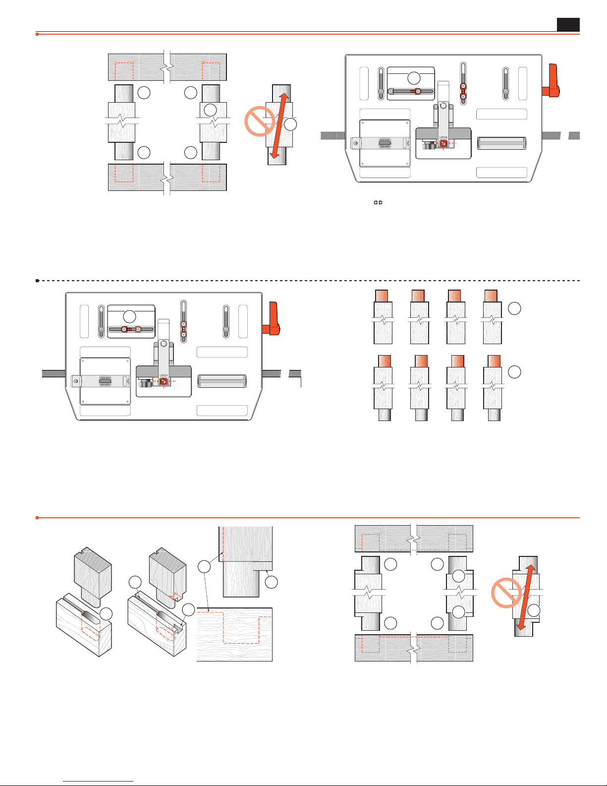
SPECIAL JOINTS
Asymmetric Tenons
Frame Mortise & Tenon Jig User Guide
1
B
A
1
2
Chapter 7
51
A
B
7-20 Asymmetric Tenons Not all tenons are centered on
the long axis of the workpiece end
. This means that tenons “A”
➀
are routed at one table sighting and tenons “B” at a second table
sighting. If you don’t, the two tenons will be diagonally opposed
to each other
➁
.
1
7-22 …sight tenon “B” and set the left-hand limit stop to the left
of the post
. Now alternately rout tenons “A” and “B”, moving
➀
the table left and right each time.
7-21 Use the
limit stops for rapid changeover from tenons
“A” to tenons “B”.
For example, with the workpiece centered on the jig, sight tenon
“A” and set the right-hand limit stop to the right of the post
➀
then…
A
B
7-23 Of course, if you don’t trust yourself to get the sequence
correct, you could rout all the “A” tenons first, then change the
table one time to rout all the “B” tenons. This latter procedure
would be the simplest way to rout haunched tenons (see next
section).
■
,
Haunched Joints
1
1
4
3
7-24 Haunched Joints Frame and panel door construction can
call for rails and stiles to be grooved for the panel
haunched
, both for joint stability and to fill the end of the stile
➁
groove which is sometimes run right through
mon as it once was. Routers and router tables now make it simple to
have a stopped groove
, avoiding the need for the haunch.
➃
2
, and the tenons
➀
. This is not as com-
➂
B
A
A
1
1
B
2
7-25 Haunched mortises and tenons are “handed”, and require
separate setups for each. e.g. if these two tenons
the same jig setup, the result would be offset tenons
were routed with
➀
. So mark
➁
out the two types of corners as “A” and “B” mortises and tenons.
Page 56

52
FB
4
Chapter 7
1
Frame Mortise & Tenon Jig User Guide
3
SPECIAL JOINTS
2
7-26 First, groove all the workpieces ➀.
The groove should be less than the mortise width
than the haunch recess
➂
.
1
2
and shallower
➁
3
7-28 “A” Mortises and Haunch Recesses Set right-hand
Limit Stop from the post, say, 3 quarters guide length ➀: e.g. 1"
3
guide, move
full depth
⁄4". Table still in “mortise center” position, rout mortise
. Raise the plunge. Move table left to the stop ➂. Lower the
➁
bit to haunch depth; set router depth turret. The router is now set for
both depths of cut. Rout haunch recess
. Repeat for all “A” mortises.
➃
BA
7-27 Sight both the “A” and “B” mortises. Set stops or mark the
outrigger for repeatable successive workpieces. Position and lock
the
Limit Stops against the post.
2
1
3 4
7-29 “B” Mortises and Haunch Recesses Move the table
left to touch the right-hand
and lock the table. Move the left-hand
quarters of the guide length) to the left
and haunch recesses
using the table movement and the same
➃
Limit Stop against the post ➀
Limit Stop (by three
. Rout the “B” mortises ➂
➁
router depth settings.
BA
7-30 Routing the Tenons Mark the tenon centers “A” and
“B”. Remember, the tenons are “off center” and each end of the tenon
pieces are marked off center in opposite directions. Prepare and make
a couple of extra (scrap) tenon pieces to use in setting haunch bit
depth later.
1
7-31 “A” tenons. With the workpiece centered on the jig,
sight the tenon center and set the right hand
the post
➀
.
limit stop to
Page 57
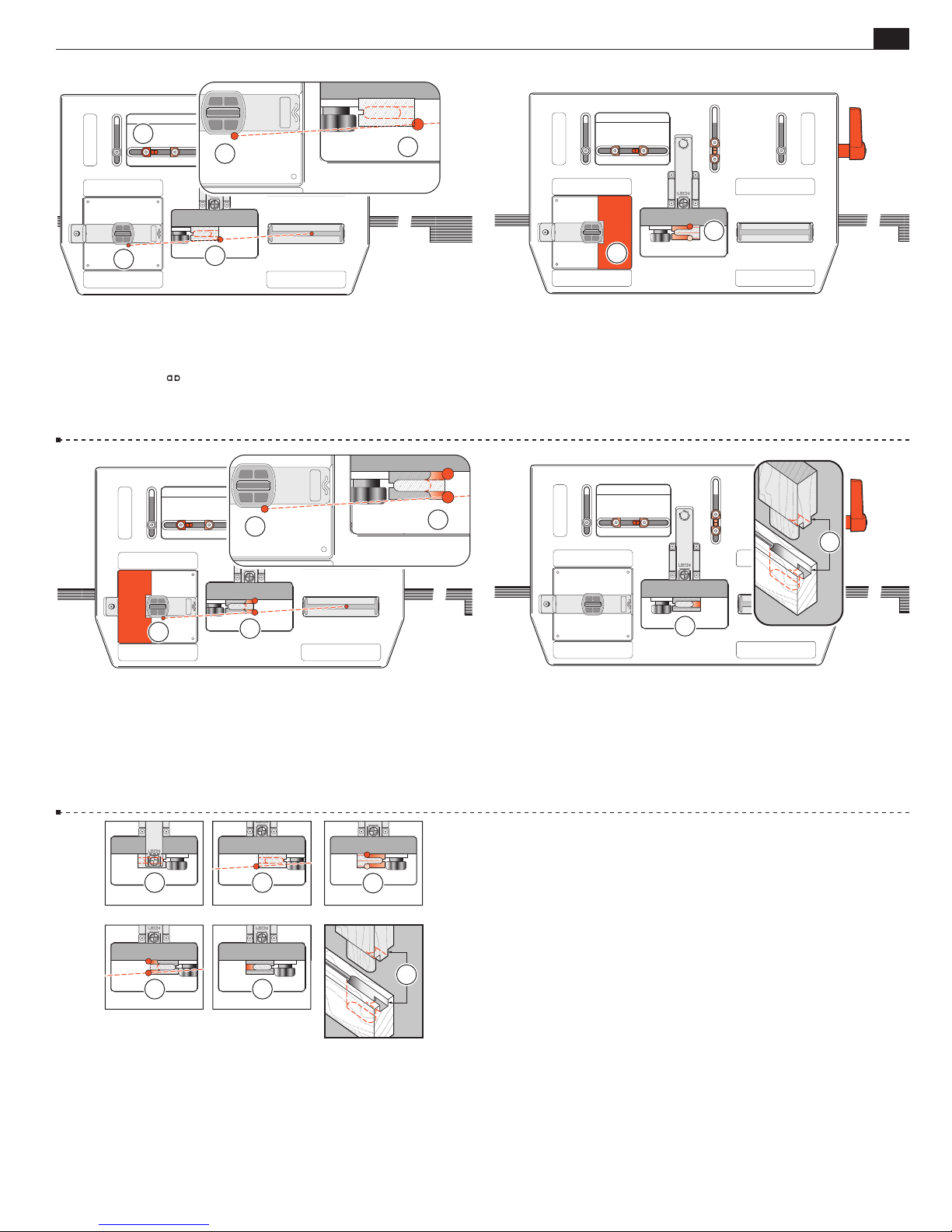
SPECIAL JOINTS
1
2
1
2
2
Frame Mortise & Tenon Jig User Guide
3
2
1
1
Chapter 7
53
7-32 Move the table right to a position where the bit will clear
the end of the haunch
part of the guide
Set the left hand
2
while the guide pin is still on the straight
➀
.
➁
limit stop to its post ➂.
1
7-34 Move the guard to the left end of the recess. Move the
table right and rout the rest of the tenon “A” at full depth; the bit
prevented from rounding the haunch off at
against the guide side at
➁
.
by the guide pin
➀
7-33 Move the table to the left again and if necessary, set a “guard”
piece in the guide recess
end of the tenon
. Rout the left end of the tenon (shaded area)
➁
to prevent routing around the right
➀
at full shoulder depth.
1
1
7-35 Move the table left, remove the guard from the bit recess.
Depth: You will have to preset the plunge router depth-of-cut
rod and turret so that the routed haunch exactly equals the depth
of the haunch recess
. Use the scrap test tenons to achieve this
➀
setting by measurement and a little trial and error. Now rout
completely around the actual tenon.
1 2
4 5
7-36 Tenons “B” on the other end are routed with the procedure
reversed.
■
3
5
Page 58
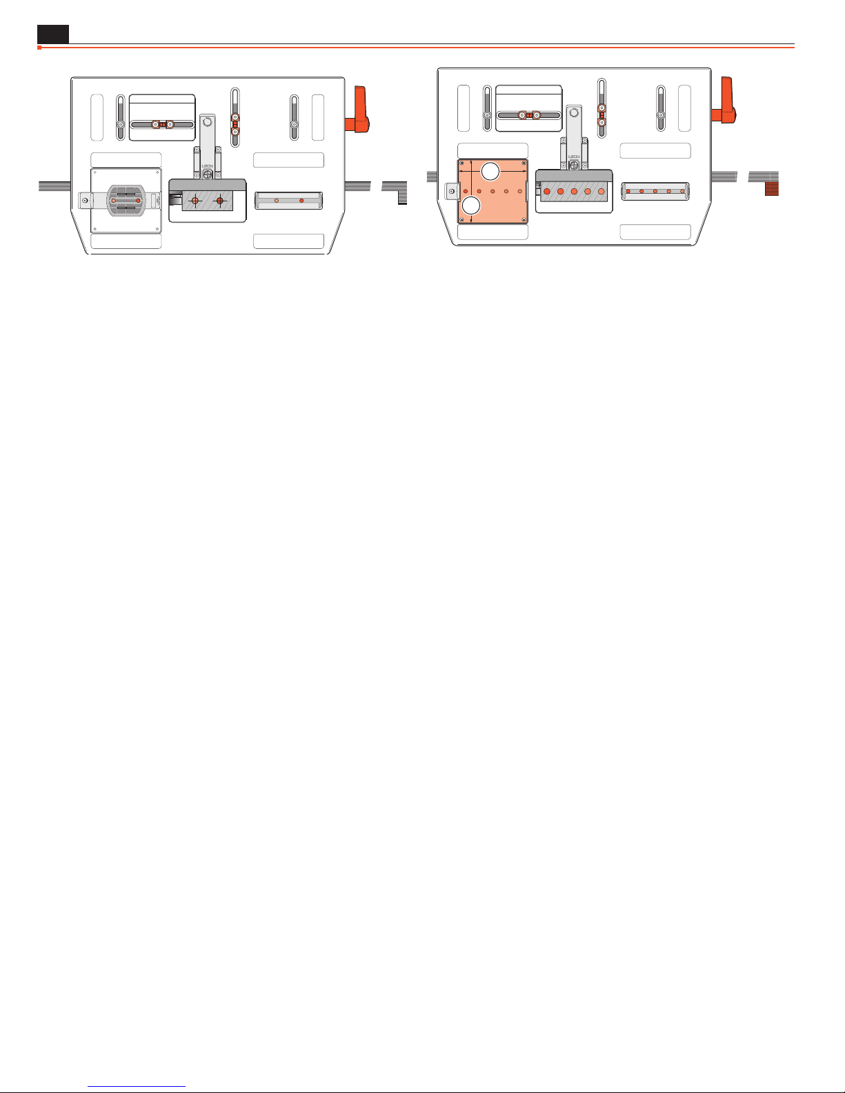
54
Doweling
Chapter 7
Frame Mortise & Tenon Jig User Guide
SPECIAL JOINTS
1
2
7-37 Doweling Sometimes where the strength of a mortise
and tenon is not required, doweling may be a suitable alternative.
A bonus use of the FMT Pro is its ability to provide very precise
dowel hole boring. Turn the left hand guide pin down to “zero
free play” in the mortise guide slot. Simply use one or both ends
of a mortise guide slot for positioning while plunging the dowel
holes, or...
7-38 ...make up your own row of dowel hole guide holes in a piece
of plywood or MDF which can be retained in the guide recess with
small flat head screws, using the four countersunk holes through
the table. Make this auxiliary “guide” dimensions:
5
⁄32➀ x 33⁄4➁[105 x 95mm]. Don’t forget, you can use the table
4
movement and limit stops to double or quadruple the number
of hole positions in the ends or side edges of boards; all precisely
indexed to each other.
■
Page 59
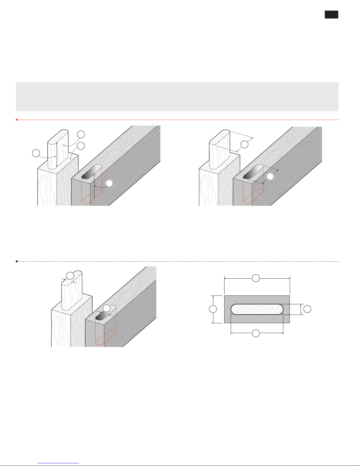
JOINT SPECIFICATIONS, GUIDE & BIT SELECTION
FMT PRO Appendix I
Joint Specifications,
Guide & Bit Selection
Foreword The illustrations and specifications in this Appendix show the largest tenon rail and tenon sizes possible
on the FMT Pro, either in one table position or multiple table positions as noted. For all smaller sizes, refer to the
guide and bit selection chart.
Joint Specifications
1
2
3
4
5
6
55
A1-1 Joint Terminology The tenon sides are the “Cheeks” ➀.
The tenon shoulders are called (luckily) the “Shoulders”
➁
.
Unfortunately, references to dimensions of mortises and tenons
do not share matching terminology, so...
Long or short tenons
fit into deep or shallow mortises ➃.
➂
Tenon Length = Mortise Depth.
7
8
A1-3
Thick or thin tenons ➆ fit into wide or narrow mortises ➇.
Tenon Thickness = Mortise Width.
A1-2
Wide or narrow tenons ➄ fit into long or short mortis-
.
es
➅
Tenon Width = Mortise Length.
2
1
4
3
A1-4 Largest Single Rail and Tenon
1
Using One Table Position with
Workpiece thickness 15⁄16"[34mm]
➀
Workpiece width 31⁄8" [80mm]
➁
Tenon thickness 1⁄2" [12mm]
➂
Tenon width 21⁄2"[65mm]
➃
Note: To rout single tenons in stock thicker than 1
⁄2" Bit
5
⁄16"[34mm] would
require the bit to be plunged into the edge of the workpiece and so
“trapping” the bit. That could be dangerous, so follow the “Third
Tenon” procedure (see 5-39 through 5-44).
Page 60
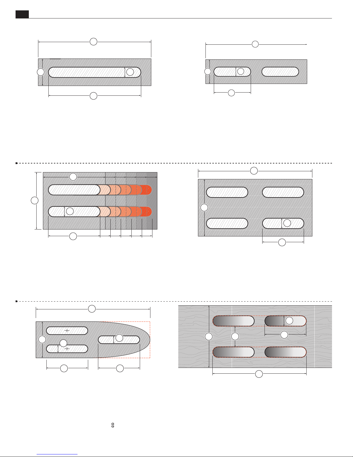
56
FB
Appendix I Frame Mortise & Tenon Jig User Guide
JOINT SPECIFICATIONS, GUIDE & BIT SELECTION
1
1
3
A1-5 Largest Single Rail and Tenon -
5
Workpiece 1
1
Tenon
Guide
*Note: Using three table positions, tenon width
⁄16" x 51⁄2"[34 x 140mm] ➀.
⁄2" x 41⁄2"*[12 x 115mm] ➁.
1
⁄2" x 21⁄2"[12 x 65mm].
1
1
2
➂
2
Two Table Positions.
may be up to 5"[125mm]
1
1
2
2
A1-6 Largest Tandem Double Tenon -
5
Workpiece 1
Tenons
Guide
⁄16" x 51⁄2"[34 x 140mm] ➀.
1
⁄2" x 2"[12 x 50mm] ➁.
1
⁄2" x 2"[12 x 50mm].
1
1
Two Table Positions.
2
A1-7 Largest Side-by-Side Twin Tenon -
1
Workpiece 3" x 5
Tenons
1
Guide
⁄2"[76 x 140mm] ➀.
⁄2" x 21⁄2
1
⁄2" x 21⁄2"[12 x 65mm].
+
"[12 x 65+mm]
Two* Table Positions.
.
➁
*Note: Add left-right table positions to the two front-back settings,
for maximum workpiece and tenons extension. See A1-5
1
1
2
A1-9 Largest Triple Tenon -
3
Workpiece 1
Tenons
Guide
⁄4 x 51⁄2"[44 x 140mm] ➀.
3
⁄8" x 2"[10 x 50mm] ➁.
3
⁄8" x 2"[10 x 50mm].
Five* Table Positions.
2
22
*Note: To avoid “trapping” the bit on larger workpieces it is necessary
to rout the third tenon in three different
table positions. See
Chapter 5, Triple Joints.
2
2
A1-8 Largest Quadruple Tenon -
1
Workpiece 3" x 5
Tenons
1
Guide
1
⁄2"[76 x 140mm] ➀.
⁄2" x 2"[12 x 50mm] ➁.
1
⁄2" x 2"[12 x 50mm].
4
Four table positions.
2
2
3
A1-10 Thickest Mortise Board and Mortise Centers –
table positions
Thickness 3"[75mm]
1
4 Mortises
2 Mortises
Spacing
⁄2" x 2"[12 x 50mm] ➁.
1
⁄2" x 41⁄2"[12 x 115mm] ➂.
9
⁄16" to 1"[13 x 26mm] ➃.
➀
.
Board Width Clamping Capacity: 5"[128mm].
Four
Page 61
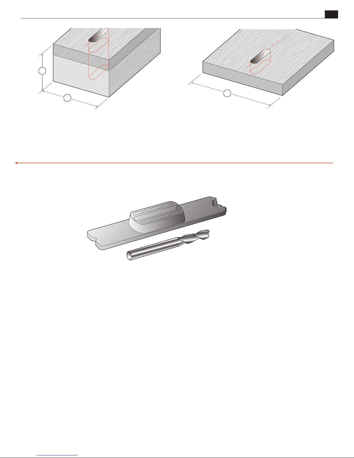
JOINT SPECIFICATIONS, GUIDE & BIT SELECTION
2
Appendix IFrame Mortise & Tenon Jig User Guide
57
1
A1-11 Maximum Mortise Board Width and Thickness
for Mortising to Center
Width up to 45⁄8"[115mm] ➀.
Thickness up to 4"[100mm]
➁
.
Note: See 6-21 mounting instructions for these pieces.
Guide and Bit Selection
1
A1-12 Maximum Width Mortise Board
for Mortising to Center
Width from 45⁄8"[115mm]
1
up to 6
See 6-22 for special instructions.
⁄2"[165mm]
➀
■
Guide and Bit Selection
Use the following charts to select appropriate guide and bit combinations.
➔
Page 62
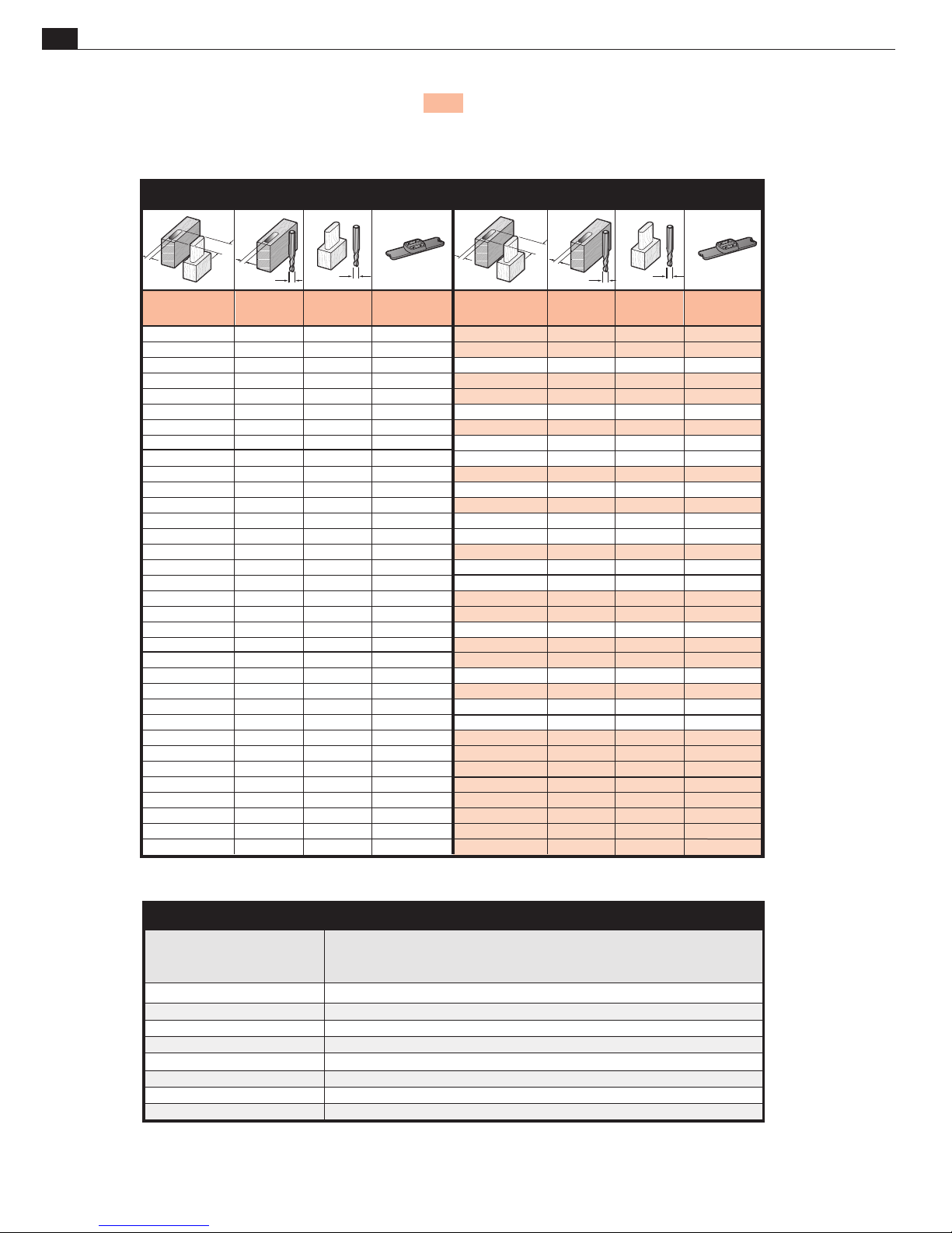
58
Appendix I Frame Mortise & Tenon Jig User Guide
Directions: Joints routed with a single bit are shown shaded. In addition to the joint sizes listed in the charts, any tenon
width (mortise length) can easily be achieved by using the jig’s quick-acting table movement and limit stops as described
in Chapter 6, Longer and Shorter Joints. By using combinations of machine tool bits, even more sizes of small and miniature
joints may be routed. See information on small joints in Chapter 4.
INCH GUIDE AND BIT SELECTION CHART
JOINT SPECIFICATIONS, GUIDE & BIT SELECTION
JOINT
SIZE
1/16" x 1/8"
1/16" x 3/16"
1/16" x 5/16"
1/16" x 7/16"
1/16" x 9/16"
1/16" x 13/16"
1/16" x 1-1/16"
1/16" x 1-5/16"
1/8" x 3/16"
1/8" x 1/4"
1/8" x 5/16"
1/8" x 3/8"
1/8" x 1/2"
1/8" x 9/16"
1/8" x 5/8"
1/8" x 13/16"
1/8" x 7/8"
1/8" x 1-1/16"
1/8" x 1-1/8"
1/8" x 1-5/16"
1/8" x 1-3/8"
3/16" x 1/4"
3/16" x 5/16"
3/16" x 3/8"
3/16" x 7/16"
3/16" x 9/16"
3/16" x 5/8"
3/16" x 11/16"
3/16" x 7/8"
3/16" x 15/16"
3/16" x 1-1/8"
3/16" x 1-3/16"
3/16" x 1-3/8"
3/16" x 1-7/16"
MORTISE
BIT
1/16
1/16
1/16
1/16
1/16
1/16
1/16
1/16
1/8
1/8
1/8
1/8
1/8
1/8
1/8
1/8
1/8
1/8
1/8
1/8
1/8
3/16
3/16
3/16
3/16
3/16
3/16
3/16
3/16
3/16
3/16
3/16
3/16
3/16
TENON
BIT
7/16
7/16
7/16
7/16
7/16
7/16
7/16
7/16
3/8
3/8
1/2
3/8
3/8
1/2
3/8
1/2
3/8
1/2
3/8
1/2
3/8
5/16
5/16
7/16
5/16
5/16
7/16
5/16
7/16
5/16
7/16
5/16
7/16
5/16
GUIDE
SIZE
1/4" x 5/16"
1/4" x 3/8"
1/4" x 1/2"
1/4" x 5/8"
1/4" x 3/4"
1/4" x 1"
1/4" x 1-1/4"
1/4" x 1-1/2"
1/4" x 5/16"
1/4" x 3/8"
5/16" x 1/2"
1/4" x 1/2"
1/4" x 5/8"
5/16" x 3/4"
1/4" x 3/4"
5/16" x 1"
1/4" x 1"
5/16" x 1-1/4"
1/4" x 1-1/4"
5/16" x 1-1/2"
1/4" x 1-1/2"
1/4" x 5/16"
1/4" x 3/8"
5/16" x 1/2"
1/4" x 1/2"
1/4" x 5/8"
5/16" x 3/4"
1/4" x 3/4"
5/16" x 1"
1/4" x 1"
5/16" x 1-1/4"
1/4" x 1-1/4"
5/16" x 1-1/2"
1/4" x 1-1/2"
JOINT
SIZE
1/4" x 5/16"
1/4" x 3/8"
1/4" x 7/16"
1/4" x 1/2"
1/4" x 5/8"
1/4" x 11/16"
1/4" x 3/4"
1/4" x 7/8"
1/4" x 15/16"
1/4" x 1"
1/4" x 1-3/16"
1/4" x 1-1/4"
1/4" x 1-3/8"
1/4" x 1-7/16"
1/4" x 1-1/2"
1/4" x 1-7/8"
1/4" x 2-3/8"
5/16" x 1/2"
5/16" x 3/4"
5/16" x 15/16"
5/16" x 1"
5/16" x 1-1/4"
5/16" x 1-7/16"
5/16" x 1-1/2"
5/16" x 1-15/16"
5/16" x 2-7/16"
3/8" x 1"
3/8" x 1-1/2"
3/8" x 2"
3/8" x 2-1/2"
1/2" x 1"
1/2" x 1-1/2"
1/2" x 2"
1/2" x 2-1/2"
MORTISE
BIT
1/4
1/4
1/4
1/4
1/4
1/4
1/4
1/4
1/4
1/4
1/4
1/4
1/4
1/4
1/4
1/4
1/4
5/16
5/16
5/16
5/16
5/16
5/16
5/16
5/16
5/16
3/8
3/8
3/8
3/8
1/2
1/2
1/2
1/2
TENON
BIT
1/4
1/4
3/8
1/4
1/4
3/8
1/4
1/2
3/8
1/4
3/8
1/4
1/2
3/8
1/4
1/2
1/2
5/16
5/16
7/16
5/16
5/16
7/16
5/16
7/16
7/16
3/8
3/8
3/8
3/8
1/2
1/2
1/2
1/2
GUIDE
SIZE
1/4" x 5/16"
1/4" x 3/8"
5/16" x 1/2"
1/4" x 1/2"
1/4" x 5/8"
5/16" x 3/4"
1/4" x 3/4"
3/8" x 1"
5/16" x 1"
1/4" x 1"
5/16" x 1-1/4"
1/4" x 1-1/4"
3/8" x 1-1/2"
5/16" x 1-1/2"
1/4" x 1-1/2"
3/8" x 2"
3/8" x 2-1/2"
5/16" x 1/2"
5/16" x 3/4"
3/8" x 1"
5/16" x 1"
5/16" x 1-1/4"
3/8" x 1-1/2"
5/16" x 1-1/2"
3/8" x 2"
3/8" x 2-1/2"
3/8" x 1"
3/8" x 1-1/2"
3/8" x 2"
3/8" x 2-1/2"
1/2" x 1"
1/2" x 1-1/2"
1/2" x 2"
1/2" x 2-1/2"
LEIGH BIT ITEM NO.
HSS Solid Carbide Mortise Size HSS Solid Carbide Shank
Spiral Upcut Spiral Upcut Cutting Diameter Cutting Depth Cutting Depth Diameter
162 N/A 1/16" 3/16" - 1/4"
164 164C 1/8" 3/8" 1/2" 1/4"
166 166C 3/16" 5/8" 3/4" 1/4"
168 168C 1/4" 1" 1-1/8" 1/4"
170-500 170-500C 5/16" 1" 1-1/4" 1/2"
173-500 173-500C 3/8" 1-1/4" 1-1/4" 1/2"
177 177C 7/16" 1-3/4" 1-3/4" 1/2"
180 180CL 1/2" 1-1/2" 2-1/8" 1/2"
INCH BIT SPECIFICATIONS
Page 63
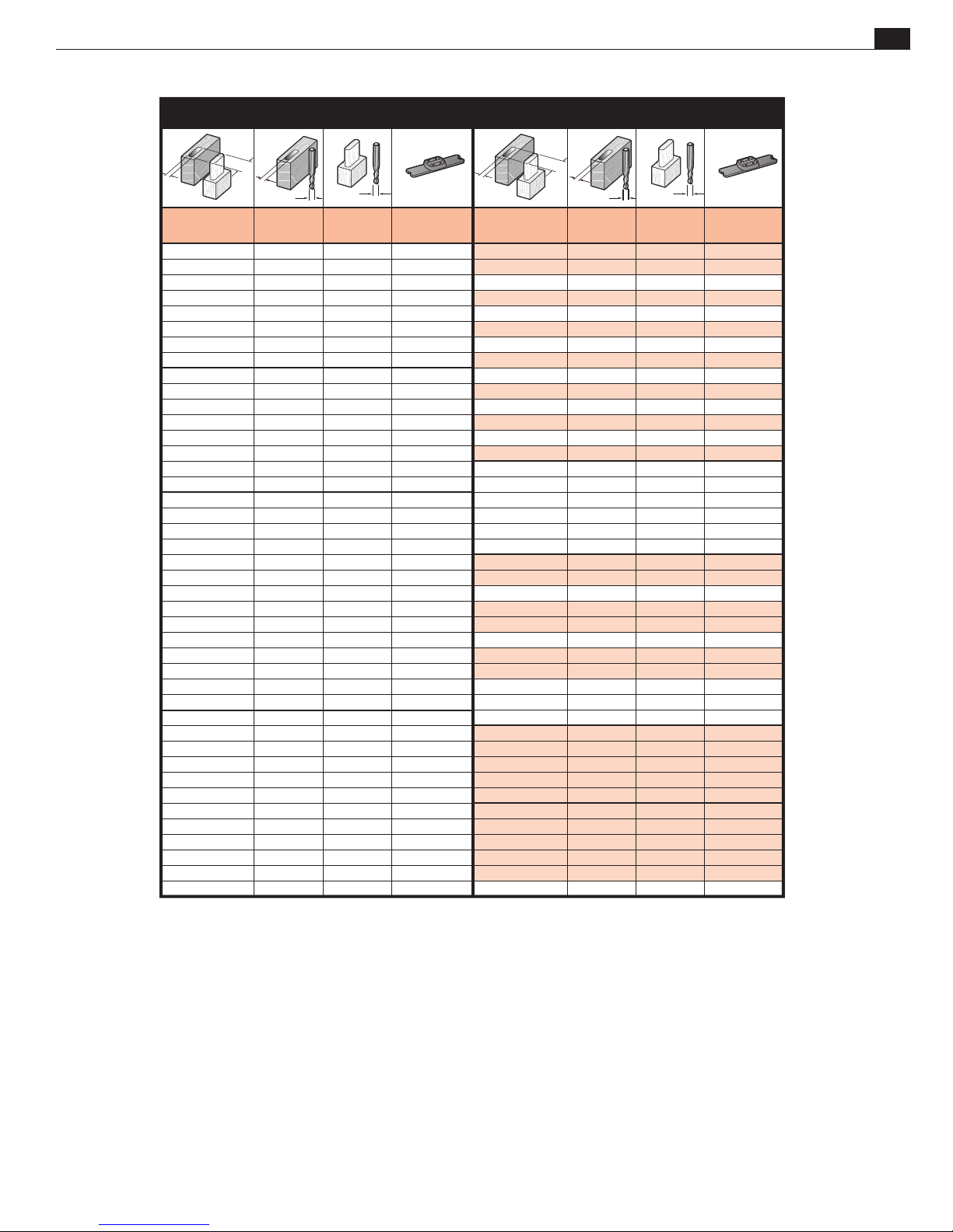
JOINT SPECIFICATIONS, GUIDE & BIT SELECTION
METRIC GUIDE AND BIT SELECTION CHART
Appendix IFrame Mortise & Tenon Jig User Guide
59
JOINT
SIZE
2 x 4
2 x 6
2 x 11
2 x 16
2 x 21
2 x 26
2 x 31
2 x 36
3 x 5
3 x 7
3 x 12
3 x 17
3 x 22
3 x 27
3 x 32
3 x 37
4 x 6
4 x 8
4 x 11
4 x 13
4 x 16
4 x 18
4 x 21
4 x 23
4 x 26
4 x 28
4 x 31
4 x 33
4 x 36
4 x 38
5 x 7
5 x 9
5 x 14
5 x 19
5 x 24
5 x 29
5 x 34
5 x 39
MOR
TISE
BIT
2
2
2
2
2
2
2
2
3
3
3
3
3
3
3
3
4
4
4
4
4
4
4
4
4
4
4
4
4
4
5
5
5
5
5
5
5
5
TENON
BIT
10
10
10
10
10
10
10
10
9
9
9
9
9
9
9
9
8
8
12
8
12
8
12
8
12
8
12
8
12
8
7
7
7
7
7
7
7
7
GUIDE
SIZE
6 x 8
6 x 10
6 x 15
6 x 20
6 x 25
6 x 30
6 x 35
6 x 40
6 x 8
6 x 10
6 x 15
6 x 20
6 x 25
6 x 30
6 x 35
6 x 40
6 x 8
6 x 10
8 x 15
6 x 15
8 x 20
6 x 20
8 x 25
6 x 25
8 x 30
6 x 30
8 x 35
6 x 35
8 x 40
6 x 40
6 x 8
6 x 10
6 x 15
6 x 20
6 x 25
6 x 30
6 x 35
6 x 40
JOINT
SIZE
6 x 8
6 x 10
6 x 13
6 x 15
6 x 18
6 x 20
6 x 23
6 x 25
6 x 28
6 x 30
6 x 33
6 x 35
6 x 38
6 x 40
7 x 14
7 x 19
7 x 24
7 x 29
7 x 34
7 x 39
8 x 15
8 x 20
8 x 23
8 x 25
8 x 30
8 x 33
8 x 35
8 x 40
8 x 43
8 x 53
8 x 63
10 x 25
10 x 35
10 x 45
10 x 55
10 x 65
12 x 25
12 x
12 x 45
12 x 55
12 x 65
35
MORTISE
BIT
6
6
6
6
6
6
6
6
6
6
6
6
6
6
7
7
7
7
7
7
8
8
8
8
8
8
8
8
8
8
8
10
10
10
10
10
12
12
12
12
12
TENON
BIT
6
6
10
6
10
6
10
6
10
6
10
6
10
6
9
9
9
9
9
9
8
8
12
8
8
12
8
8
12
12
12
10
10
10
10
10
12
12
12
12
12
GUIDE
SIZE
6 x 8
6 x 10
8 x 15
6 x 15
8 x 20
6 x 20
8 x 25
6 x 25
8 x 30
6 x 30
8 x 35
6 x 35
8 x 40
6 x 40
8 x 15
8 x 20
8 x 25
8 x 30
8 x 35
8 x 40
8 x 15
8 x 20
10 x 25
8 x 25
8 x 30
10 x 35
8 x 35
8 x 40
10 x 45
10 x 55
10 x 65
10 x 25
10 x 35
10 x 45
10 x 55
10 x 65
12 x 25
12 x 35
12 x 45
12 x 55
12 x 65
METRIC BIT SPECIFICATIONS
Important Note: Due to limited availability of metric bits in North America, Leigh does not stock
or sell metric bits. Contact the national Leigh distributor or local supplier in your region.
Page 64

60
Appendix I Frame Mortise & Tenon Jig User Guide
JOINT SPECIFICATIONS, GUIDE & BIT SELECTION
Page 65
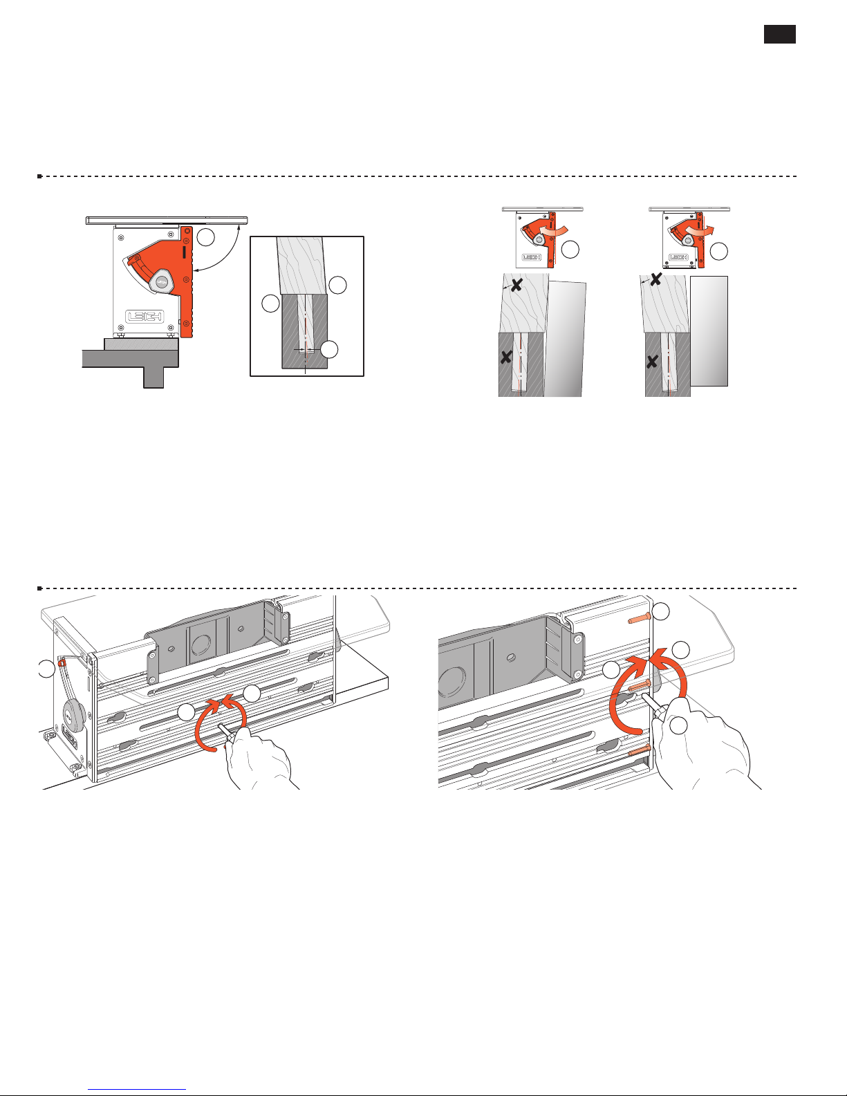
JIG ADJUSTMENTS
61
FMT PRO Appendix II
Jig Adjustments
1
90˚
2
2
3
A2-1 Clamp Plate The Clamp Plate is factory set square to
the table
. However, this does not guarantee perfectly in-line
➀
joints. If your router shaft and bit are not perpendicular to the
router sub-base and the Leigh Sub-Base, then the bit will not be
square to the Jig Table (nor parallel to the Clamp Plate). This will
cause a tiny “step” in the joint alignment
. This is because the
➁
tenon center mark is now offset from the mortise center mark in
the assembled joint
. For clarity, the angle and step in this example
➂
is highly exaggerated.
1
A2-2
Check your test joints for alignment with a straightedge.
2
The cross represents the inside face toward the clamp face.
The left example shows the clamp plate should be adjusted in
toward the jig body
plate should be adjusted away from the jig body
. The right example shows the clamp
➀
. Test and
➁
adjust the Clamp Plate angle (see A2-3) until the workpieces are
in the same plane, with no joint misalignment.
1
3
1
2
A2-3 The adjusting screw for setting the clamp plate is in the
lower center of the plate. Loosen the quadrant knobs. Use the hex
screwdriver to turn the screw counterclockwise to move the plate
. Turn the screw clockwise to move the plate out ➁. The screw
in
➀
is treated with Loctite™ to prevent accidental rotation. When the
clamp plate is square, re-zero the angle indicator if necessary
➂
.
4
3
2
A2-4 Joint Alignment
The Clamp Plate is precision-set parallel
to the table at the factory and should never need attention. However,
if it should need adjustment, here’s how. First, loosen the two quadrant
knobs and tilt the Clamp Plate up approximately 1/4" and re-tighten
the knobs. Then slightly loosen the three screws holding the right end
quadrant using the square drive screwdriver
turn the setscrew in this hole
Clamp Plate in toward the jig
then tighten the quadrant screws
clockwise to move the right end of the
➁
; counterclockwise to move it out ➃,
➂
. The adjusting screw is 28 pitch;
➀
. Use the hex driver to
➀
one turn is 0.036"[,9mm]. That’s a lot. If adjustment is ever necessary
it will likely be a small fraction of a turn.
Page 66
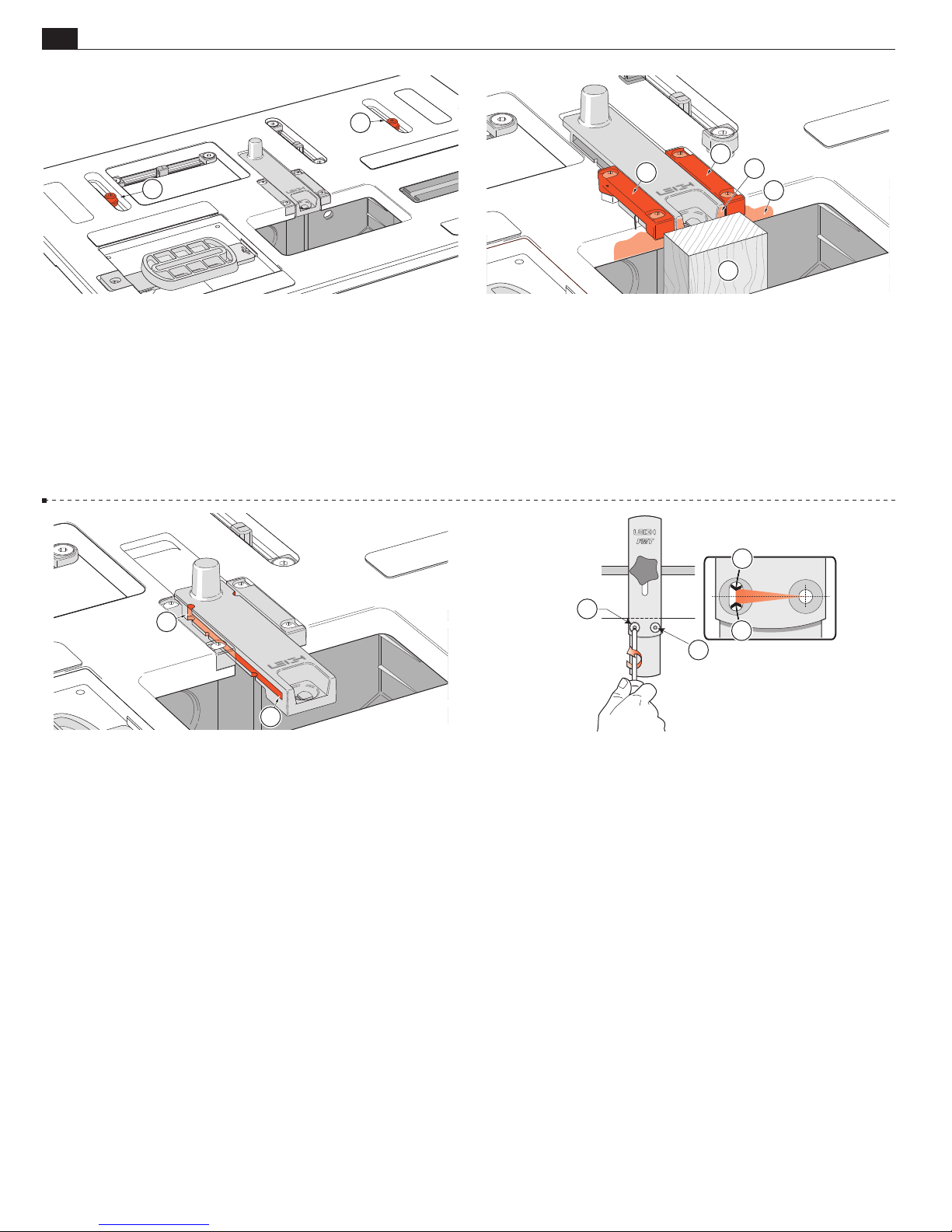
62
Appendix II Frame Mortise & Tenon Jig User Guide
1
1
JIG ADJUSTMENTS
2
2
4
3
1
A2-5 Table Clamp Setting
The setting for this is factory pre-set
using a torque tool. Should you need to adjust the pressure, lock
the table and lightly tighten the two clamp screws equally
➀
. Do
not adjust these screws with the table unlocked. You should be
able to work the table lock lever with quite light pressure. When
locked, it should not be possible to move the table with firm side
to side hand and arm pressure. When unlocked, it should be easy
to position the table without sticking. The screws are treated with
Loctite™ to prevent accidental rotation.
2
1
A2-7 Jig Maintenance
Very little maintenance is required. Fine
dust build-up in the front and rear sight stops should be removed
from time to time. The end of the small hex key or a piece of wire
will do the trick. At the front
position at
. Dusting off with compressed air (if available) will
➁
and with the sight to the rear
➀
keep the jig clean.
A2-6 Sight Position
The sight position is factory set. If you
ever need to reset it here’s how. Clamp a straight vertical rail that
projects through the table bit opening
four small hex cap screws that hold the two sight rails
. Slightly loosen the
➀
using
➁
the provided hex key. Move the table forward until the rear edge
of the bit opening
the table. Pull the sight and rails against the wood piece
firmly touches the vertical rail ➀, and lock
➂
; at the
➃
same time centring the rear end of the sight in the recess. Tighten
the four screws.
3
1
3
2
A2-8 The sidestop fence is squared at the factory, but check your first
test joints. If your router/bit is not perfectly perpendicular to the table
adjust the sidestop fence: slightly loosen the 'pivot' screw
screw
. Adjust the angle ➂ to match the bit and retighten. Rout test
➁
and the 'lock'
➀
joints to confirm correct setting. Once locked in this position it should
never need adjusting when used with that same router.
■
Page 67

CUSTOMER SUPPORT
FMT PRO Appendix III
FMT Pro Parts List
Foreword See the following pages for part drawings and part numbers. Please call Leigh to order parts.
63
Page 68

64
Appendix III Frame Mortise & Tenon Jig User Guide
QUANTITY
PART NO. PER JIG PART DESCRIPTION
311 2 1/2" x 3" Compression Springs
371 4 1/4" x 7/8" x .031" Nylon Washers
371R 2 9/32" x 7/8" x .016" Nylon Washers
501 3 8-32 x 3/8" Square Socket No.2 Robertson
5100 2 Sub-Base Fence Rods 8.453" long, 7mm dia.
5130 2 M6x14mm Hex Socket Button Hd Cap Screws (for Festool)
6001 1 LH End Housing
6006 1 RH End Housing
6011 1 Top Extrusion
6015 1 Bottom Extrusion
6020 3 10 x 1-1/4" Self tapping No.2 Robertson Oval Hd Screws
6030 6 1/4 - 20 Hex Nuts (for Quadrant Knobs & Jig Hold-down)
6040 2 Limit Stop Posts
6050 1 Angle Indicator Decal
6055 1 UHMW Strip Long
6056 3 UHMW Strip Short
6060 4 1/4-20 x 1" Flat Hd Machine Screws (Jig Hold-down)
CUSTOMER SUPPORT
6101 1 Clamp Plate
6106 1 Vacuum Box
6107 1 Vacuum Box Swivel
6108 1 Vacuum Hose Adaptor – Small
6109 1 Vacuum Hose Adaptor – Large
6110 1 LH Quadrant
6115 1 RH Quadrant
6120 2 Quadrant Bushings
6125 3 Hex Socket Flat Point Set Screws 1/4-28 x 3/8"
6130 2 Outrigger Bars
6135 1 Quadrant Angle Indicator
6140 8 6-32 x 3/8" Hex Socket Button Hd Screws
6145 3 10 x 1-1/4" Self Tapping No.2 Robertson SQ Drive Pan Hd Screws
6155 5 Hex Socket Flat Point Set Screw 1/4-28 X 5/8"
6166A Side Stop Fence Assembly complete
6027 1 Washer - 3mm
6166 1 Side Stop Fence Body
6171 1 Side Stop Squaring Block
6191 1 T-Bolt
6199 2 Washers
6410 2 10-24 x 3/8" Hex Socket Button Hd Cap Screw
9530 1 Lever
6410 4 10-24 x 3/8" Hex Socket Button Hd Cap Screws (for attaching vacuum box)
6195 8 8-32 x 3/4" Flat Hd Machine Screws (for Outrigger & Low Shim Spacers)
6196 4 8-32 Hex Nuts (for Outriggers)
6200 2 Clamp T-Bolts 3/8"-16
6205 3 3/8" x 3/4" x .062" Nylon Flat Washers
6210 2 3/8-16 Clamp T-Bolt Brass nuts
6220 2 Clamp Arm
6225 2 Clamp Arm Heel Pads
6230 2 Clamp Arm Toe Pads
6235 2 Clamp Swivel Pads
6240 2 Clamp Lifters
6245 2 Clamp Lifter Springs
7025 2 Quadrant Knobs
7145 8 10 x 1-1/4" Self Tapping No.2 Robertson SQ Drive Pan Hd Screws
7225R 1 Top Extrusion Stop Post Screw
801-375 2 Cam-Action Speed Clamps
802-375 2 Speed Clamp Step Washers
Page 69
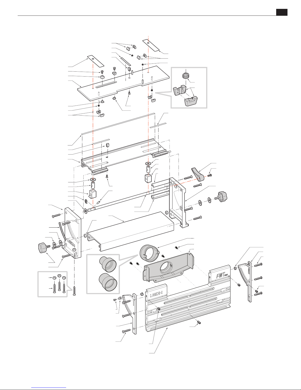
CUSTOMER SUPPORT
6335
6330
6320
6300
6310
6315
6056
6040
6335
6310
6315
6315
6310
Appendix IIIFrame Mortise & Tenon Jig User Guide
65
6001
6050
371R
371
7025
7145
6325
6315
6310
6055
6056
6040
6011
371
6415
6420
6455
6205
6108
6015
6030
7225R
6445
6400
6406
501
6325
371
6415
6425
6407
6056
6107
6410
6106
6405
6410
6006
6120
6115
6145
6030
6109
6060
6140
6135
6110
6020
6125
6155
6125
6101
Page 70

66
Appendix III Frame Mortise & Tenon Jig User Guide
QUANTITY
PART NO. PER JIG PART DESCRIPTION
6300 1 Intermediate Plate Assembly c/w pressed-in Pins
6310 4 pairs Wedge Blocks
6315 4 Wedge Block Compression Springs
6320 4 Limit Stops
6325 4 Limit Stop Nuts
6330 4 10-24 x 3/8" Hex Socket Nyloc Flat Hd Machine Screws
6335 2 UHMW Glides
6400 1 Table Clamp Rod
6405 1 Table Clamp Handle
6406 1 Clamp Handle Sleeve - Lower
6407 1 Clamp Handle Sleeve - Upper
6410 6 10-24 x 3/8" Hex Socket Button Hd Cap Screw
6415 2 "Pull Down" Clamp Block
6420 1 LH "Push-Up" Clamp Sleeve
6425 1 RH "Push-Up" Clamp Sleeve
6430 2 Hex Socket Hd Shoulder Screws 1/4" x 3/4" (10-24)
6435 2 1/4" Flat Washers SS
6440 2 1/4" Fiber Washers
6445 1 5/32" x 1" Spring Pin
6455 1 Snap Ring 3/8" x .035" thick
CUSTOMER SUPPORT
6500 1 Table Plate Assembly c/w Decals & Teflon Pads
6505 1 Sight
6510 1 LH Sight Rail
6515 1 RH Sight Rail
6530 2 Sight Rail Spring Detents
6535 1 RH Guide Pin "Track"
6540 4 Teflon Decal Pads
6550 1 Guide Latch
6555 1 Guide Latch Spring
6600 1 Sub-Base Plate Assembly c/w Decals & Teflon Pads
6605 1 LH Teflon Pad
6611 2 Teflon Discs
6615 2 Guide Pins
6620 2 Guide Pin Bushes
6625 2 Guide Pin Knobs
6626 2 Guide Pin Height Washers
6630 2 O-rings 4.5mm I.D. x 1mm
6633 2 O-rings 7.0mm I.D. x 1mm
6635 4 Sub-Base U-posts ( includes screws 6155 and 6195)
6640 4 "Low" Shim-Spacers
6645 4 "High" Shim-Spacers
6655 4 8-32 x 1" No.2 Sq Dr Flat Hd Machine Screws (for High-Shims)
6660 1 Sub-Base Handle
6665 1 "INCH" Mandrel (1/4" and 1/2")
6670 1 "METRIC" Mandrel (8mm and 12mm)
Page 71
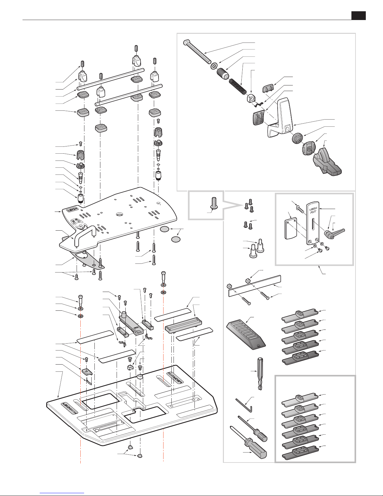
CUSTOMER SUPPORT
6155
6635
5100
6640
6645
6140
6625
6626
6615
6633
6630
6620
6200
6205
6210
311
6240
6230
6245
6225
Appendix IIIFrame Mortise & Tenon Jig User Guide
67
6220
6235
802-375
801-375
6600
6660
6605
501
6430
6435
6440
6540
6140
6550
6555
6500
6140
6505
6510
6530
6195
6655
6515
6530
6320
6330
6410
6611
6540
6535
6540
6665
6670
170-500
5130
6196
6700
6191
6171
6166
6027
9530
6199
6410
6166A
6130
6195
670508
670512
670516
670520
670524
FMT-M "Metric" Guides
6325
550
3156
6905
680815
680820
680825
680830
680835
680840
Page 72
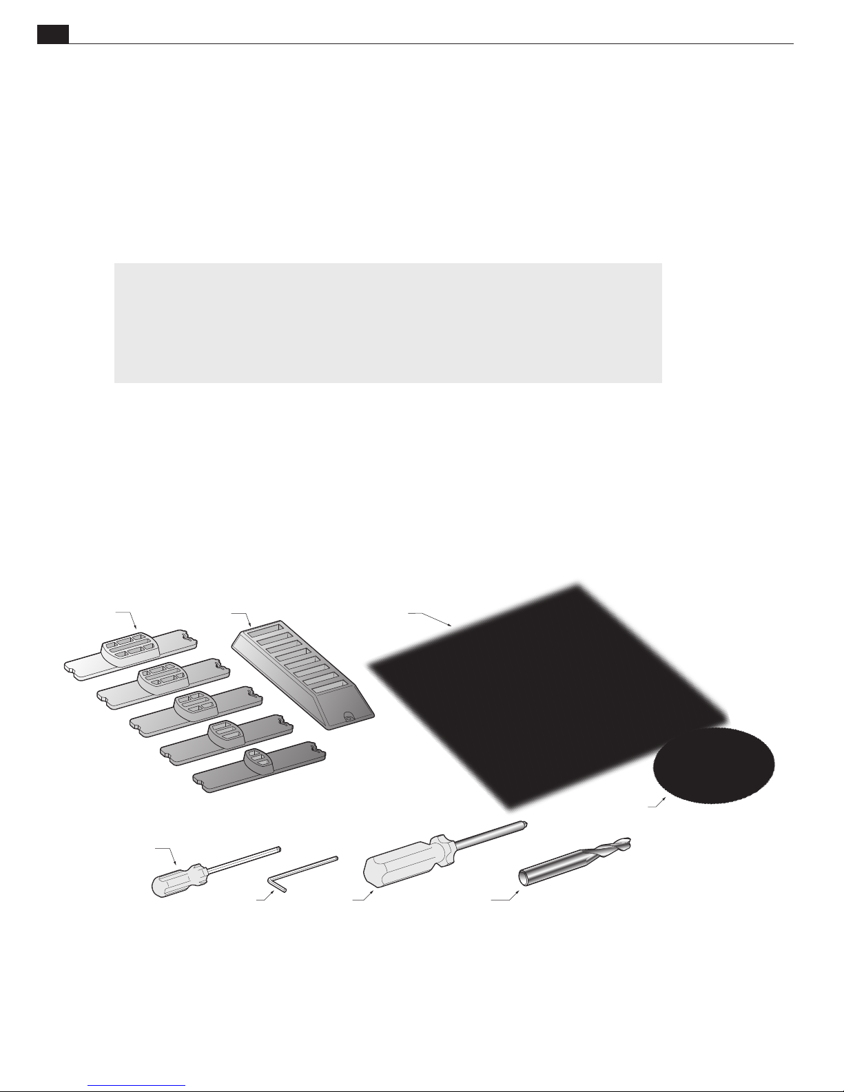
68
Appendix III Frame Mortise & Tenon Jig User Guide
QUANTITY
PART NO. PER JIG PART DESCRIPTION
670508 1 5/16" x 1/2" Template Guide
670512 1 5/16" x 3/4" Template Guide
670516 1 5/16" x 1" Template Guide
670520 1 5/16" x 1-1/4" Template Guide
670524 1 5/16" x 1-1/2" Template Guide
FMT Pro-M Metric Guides
680815 1 8 mm x 15 mm Template Guide
680820 1 8 mm x 20 mm Template Guide
680825 1 8 mm x 25 mm Template Guide
680830 1 8 mm x 30 mm Template Guide
680835 1 8 mm x 35 mm Template Guide
680840 1 8 mm x 40 mm Template Guide
6700 1 Template Guide Stand
CUSTOMER SUPPORT
6900 1 User Guide, Fully illustrated, English
6950 1 DVD Video, Instructional, English
6905 1 Leigh 1/8" Ball End Hex Screwdriver
3156 1 5/64" Hex Key (for No.6 Button Hd)
550 1 Leigh No.2 Robertson Screwdriver
170-500 1 5/16" dia. x 1/2" Shank HSS Spiral Upcut Bit
GUIDES 6700
6900
6950
6905
3156 550 170-500
Page 73

CUSTOMER SUPPORT
69
FMT PRO Appendix IV
Customer Support
Our Commitment to You Leigh Industries takes pride in its commitment to providing excellence in customer service and support. This
user guide is designed to provide you with the answers to any questions you have. However, if you require assistance, please feel free to
contact our technical support staff or a distributor listed below.
Manufacturer: Canada/USA
NOTE:
TEL/FAX
Customer Service
and Technical Support
800-663-8932
604-464-2700 (Tel.)
604 464-7404 (Fax.)
Distributors
(Canada/USA)
EMAIL/WEB
Customer Service
Technical Support
Website
www.leighjigs.com
Email can be useful, but
technical queries usually raise
queries from us. A phone call is
the quickest and most convenient
way to get queries answered,
either directly to Leigh (toll free
in N. America) or to your national
distributor.
–Thanks!
MAILING ADDRESS
Leigh Industries Ltd.
P.O. Box 357
Port Coquitlam, B.C.
Canada V3C 4K6
LOCATION
Leigh Industries Ltd.
1615 Industrial Ave.
Port Coquitlam, B.C.
Canada V3C 6M9
AUSTRALIA & NEW ZEALAND
Maxis Distribution
128 Ingleston Rd., Wakerley, Qld., 4154
Australia
Tel: 1300 767 366
Tel (Int.) +61 7 3292 0392
Email: [email protected]
Web: www.maxis.com.au
CHINA
Harvey Industries Co., Ltd.
68-10 Suyuan Avenue
Jiangning District Nanjing 211100, China
Tel: (0)86 5792 8869 / 5792 8021
Fax: (0)86 5792 8826
Email: [email protected]
Website: www.harveyworks.cn
FRANCE
Ets Bordet
23 Rue Traversiere 93556
Montreuil Cedex, France
Tel: 01 48 58 28 39
Fax: 01 48 58 48 58
Email: [email protected]
Web: www.bordet.fr
GERMANY, AUSTRIA & SWITZERLAND
Hacker GmbH
Holzbearbeitungsmaschinen
Traberhofstraße 103 D-83026 Rosenheim
Deutschland
Tel: 08031 269650
Fax: 08031 68221
Email: [email protected]
Web: www.leigh.de
ITALY
Ferrari Macchine Legno SRL
Via Gallarata 74/76/78
20019 Settimo M.se (MI) Italy
Tel: 39 02 335 010 95
Fax: 39 02 335 005 27
Email: [email protected]
Web: www.ferrarimacchine.com
JAPAN
Off Corporation Inc.
323-1 Yanbara, Shimizu-ku, Shizuoka-shi
Shizuoka-ken, Japan 424-0002
Tel: 81-50-3816-0115
Fax: 81-54-367-6515
Email: [email protected]
Web: www.off.co.jp
KOREA
Leigh Korea
1st Floor, Yongyu Building, 25-3
Neung Pyung-Ri, Opo-Eup, Kwangju-Si
Kyunggi-do, Korea
Tel: 82 (0) 70-8252-0988
Fax: 82 (0) 31-765-5602
Email: [email protected]
Web: www.leigh.co.kr
NETHERLANDS, BELGIUM
& LUXEMBOURG
Houtbewerking Krielaart
9217RR Nijega, Netherlands
Tel: +31 512 354 770
Email: [email protected]
Web: http://www.leighjigs.nl
RUSSIA
Unicom Ltd.
Nikitskij Boulevard 12
Moscow, 119019, Russia
Tel: 7 (495) 690 0454
Email: [email protected]
Web: www.leighjigs.ru
SOUTH AFRICA
Hardware Centre
PO Box 4059, Randburg 2125
South Africa
Tel: +27 011 791-0844/46
Fax: +27 011 791-0850
Email: [email protected]
Web: www.hardwarecentre.co.za
SWEDEN
Toolbox Sweden AB
Bruksgatan 3, S-597 30
Atvidaberg, Sweden
Tel: 46 120 854 50
Fax: 46 120 854 69
Email: [email protected]
Web: http://www.toolbox.se
UNITED KINGDOM & IRELAND
Axminster Tools & Machinery
Headquarters, Unit 10, Weycroft Avenue
Axminster, Devon
EX13 5PH United Kingdom
Tel: 0800 371822
Text: 07786 200699
Email: [email protected]
Web: www.axminster.co.uk/leigh
© 2002 Leigh Industries Ltd. All rights reserved. No part of
this publication may be reproduced, stored in a retrieval
system, or transmitted in any form or by any means, electronic,
mechanical, recording, or otherwise, without the prior written
permission of Leigh Industries Ltd. Updated 04/2017
Page 74

Joining Tradition with Today
Leigh Router Joinery Jigs
Printed in Canada
 Loading...