

Page 1
Using the F3, F18 and F24 Finger Joint Templates
on Leigh D-Series & SuperJigs
FINGER JOINT
TEMPLATES
LEIGH
DEDICATED CUSTOMER SUPPORT
1-800-663-8932
Page 2
ii
Introduction F3, F18 & F24 FINGER JOINT TEMPLATES USERGUIDE
FOREWORD
Your new Leigh Finger Joint Template
You now own a superb finger jointing system. The
Leigh Finger Joint template and adjustable e-Bush
will help you rout finger or box joints with unique
adjustment for precise tightness of fit.
“Finger” and “Box”: Both words are used universally to title this simple but strong joint. As the first
machine-made joint, it’s old enough to be called
antique, so we have been even-handed in using both
terms throughout this guide.
We recommend that you first mount the template on
your Leigh Jig, carefully following the instructions
in the first section of the user guide. Then before
you try to do any actual joinery routing, read the
rest of the guide, following along with the basic
functions. By all means, cut a few practice joints in
scrap boards before you use the template to rout a
precious hardwood workpiece.
If you have any questions that are not answered in this
user guide, please call Leigh international customer
support: 1-800-663-8932
or email: [email protected].
For support contacts in your country of purchase
see Appendix IV – Customer Support.
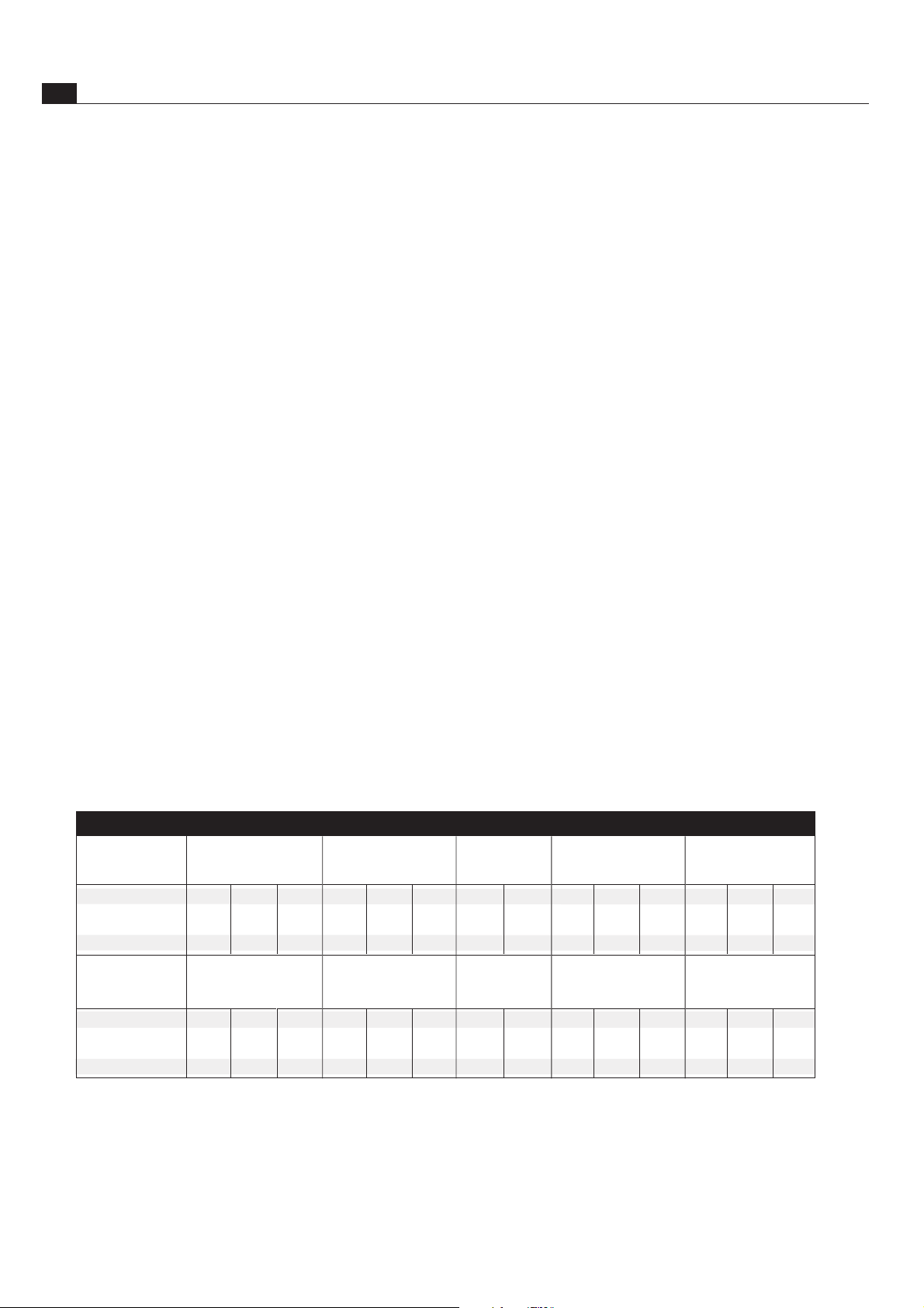
Inch
Metric
Templates
Full Size
(Inches)
Templates
Full Size
(mm)
F3 5/16 3/8 1/2
3/8 1/2
3/8 1/2
8 10 12
10 12
10 12
F18
F24
F3M
F18M
F24M
Half-Blind
(Inches)
Half-Blind
(mm)
5/16 3/8 1/2
3/8 1/2
3/8 1/2
8 10 12
10 12
10 12
Double Sizes
(Inches)
Double Sizes
(mm)
5/8 3/4 1
3/4 1
3/4 1
16 20 24
20 24
20 24
Half Size
(Inches)
Half Size
(mm)
5/32 3/16 1/4
3/16 1/4
3/16 1/4
4 6
5 6
5 6
Quarter Size
(Inches)
Quarter Size
(mm)
3/32 1/8
3/32 1/8
3/32 1/8
2
3
3
L E I G H F I N G E R ( B O X ) J O I N T S I Z E S
Page 3
iii
CONTENTS
IntroductionF3, F18 & F24 FINGER JOINT TEMPLATES USERGUIDE
INTRODUCTION ..............................................................................................ii
Chapter 1 – Assembly, Mounting, and Template Alignment .......................1
Chapter 2 – Using Your Template Safely .......................................................5
Chapter 3 – Operation Concept and Basic Template Functions ...................7
Chapter 4 – Guidebushes and the Unique Leigh e-Bush..............................9
Chapter 5 – Board Width Selection ............................................................. 11
Chapter 6 – Box Joint Procedures ................................................................13
Chapter 7 – Half-Blind Box Joint Procedures .............................................. 17
Chapter 8 – Half, Quarter, and Double Size Box Joints ..............................19
Chapter 9 – Hints and Tips ........................................................................... 25
Appendix I – Attaching the Leigh e-Bush to the Router ............................27
Appendix II – Bit Selection and Joint Specification ....................................29
Appendix III – Template Parts List ...............................................................31
Appendix IV – Customer Support................................................................35
Although joint sizes may differ
between the F3, F18 and F24,
everything in these frames is
operationally identical
COMBINED
INCH &
METRIC
SCALES
No. While the F18 and F24 are illustrated for most of the procedures in this guide, the differences between the F3 and the F18/24
do not affect the operational instructions. Movements and settings
Are there operational differences between the F3 and F18/24?
illustrated in each step are identical whether performed on the
F3/F3M, F18/24, or F18M/24M. Icon types for template pin
positions are the same on all templates.
D4R STYLE
SUPPORT
BRACKETS
COMBINED
INCH & METRIC
SCALES
SUPERJIG
STYLE SUPPORT
BRACKETS
F18/F18M
F3/F3M
Page 4
iv
Introduction F3, F18 & F24 FINGER JOINT TEMPLATES USERGUIDE
TERMINOLOGY
Important: Inches and Millimetres
Because Leigh makes F3, F18 and F24 Templates in inch and
metric models, measurements in this user guide are shown in both
inches and millimetres. Dimensions are indicated with "inches"
first, followed by "millimetres" in square parentheses.
Examples:
1
⁄2"[12mm], or
3
⁄4"x51⁄2"x8" or longer [20x140x200mm].
Do not be concerned if the inch/millimetre equivalents are not
always exact. Just use the dimensions which apply to your jig.
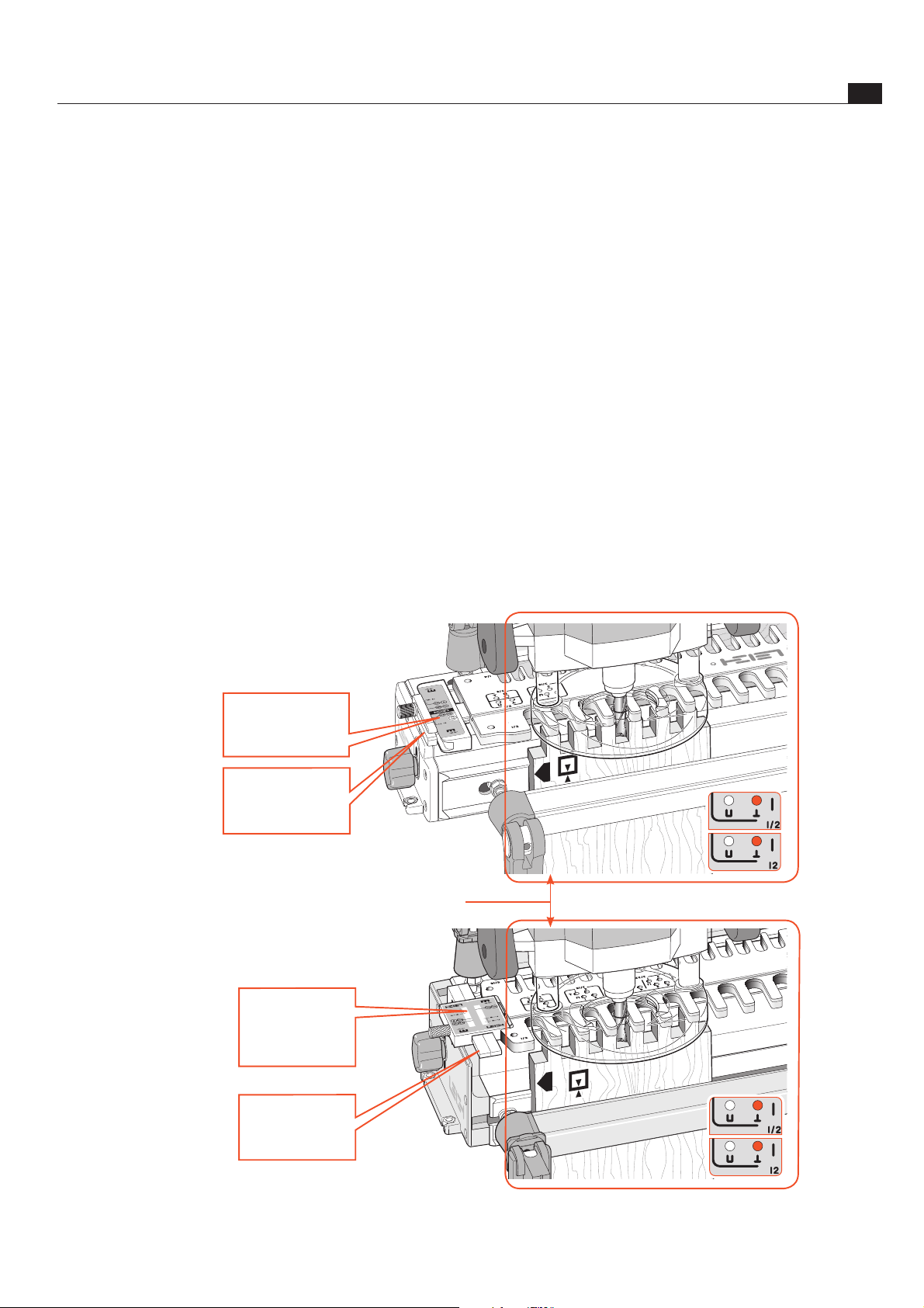
Reading the Settings Illustrations
The F Template scales have dual markings for inch and metric.
Note: The scales on some templates may indicate a
1
⁄4"[6mm] size. This
comb size is only available on F1600 Templates.
The template scales are illustrated in a panel overlaying the main
illustration
~
when settings are specified in an instruction. The
inactive (upside down) part of the scale is not shown in the illustration.
Scale settings for instructions are shown with a
red line .
When calibration marks on the support brackets
are high-
lighted, they are illustrated in
red for clarity. On the jig, the lines
are black.
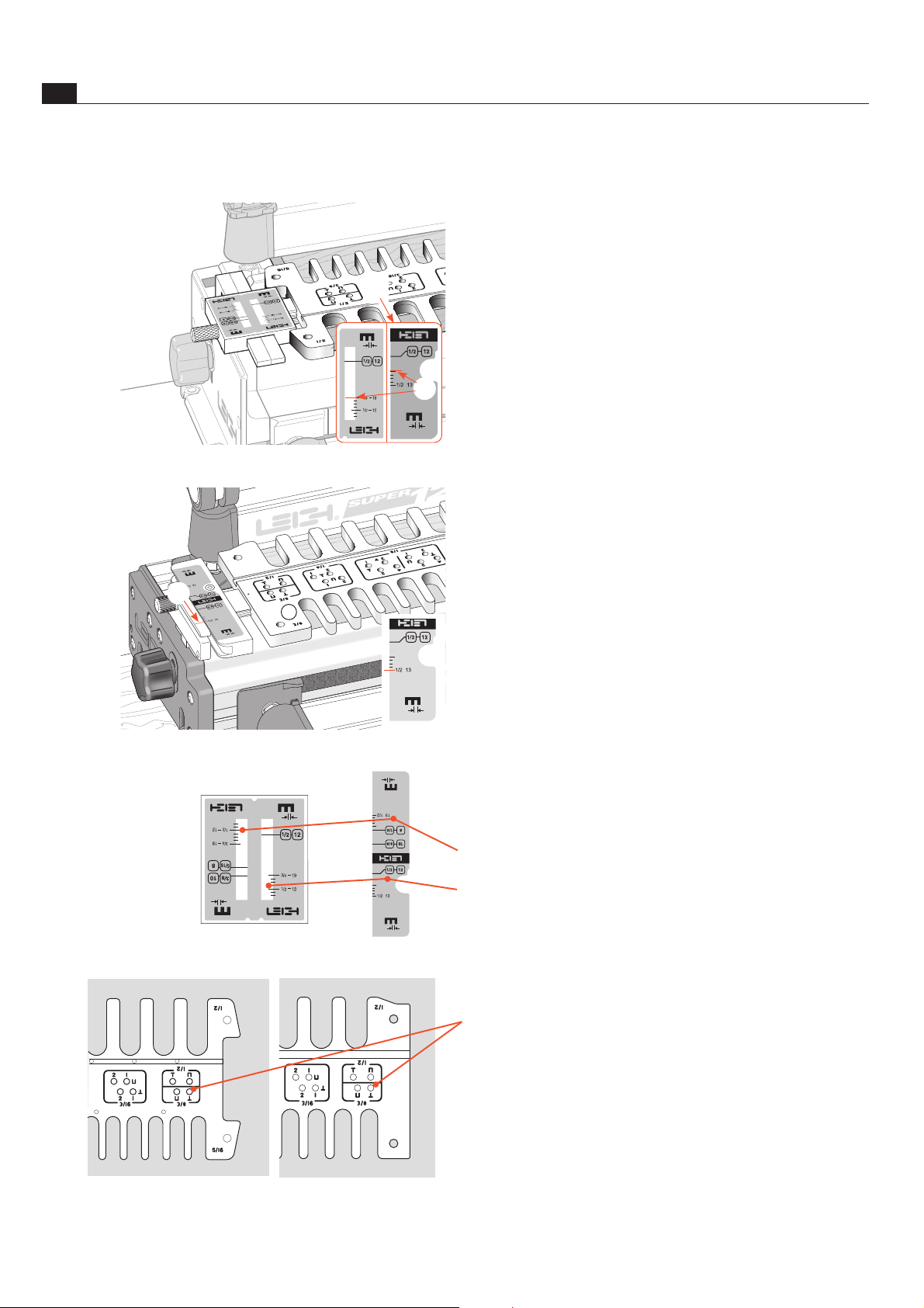
Scale Icons
The Leigh Finger Joint Template has two modes. Position the
selected comb to the front (toward you, the operator). This
places the
Inactive scale upside down.
and
Active scale right side up.
Template Icons and Numbers (engraved)
Template positioning holes (see page 7)
~
3
Page 5
v
IntroductionF3, F18 & F24 FINGER JOINT TEMPLATES USERGUIDE
TERMINOLOGY
Which Way Round Should the Board Go?
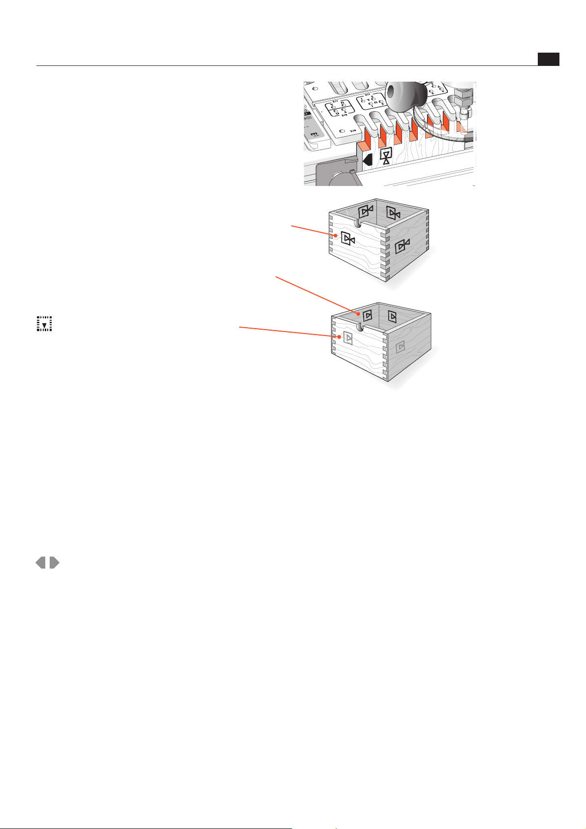
We devised these icons to indicate which side of a board faces out
(toward you when it is clamped in the jig), and which faces are in
or out when assembled.
0
Boards are clamped in the jig both “face in” and “face out” for
alternate end cuts; e.g. all regular box joint ends are routed this
way
/
Inside of board. All half-blind box joints are clamped in the
jig with the inside
/
face away from the jig toward you, the
operator.
Shaded icons are on the other side of the board.
How to Read the Symbols
To help you understand the instructions and illustrations in this
user guide, we have used a number of international symbols, plus
a few special ones of our own. They are all explained below. You
needn’t worry about memorizing these symbols now because they
are repeated frequently throughout the guide, and you will soon
get used to them.
The following symbols indicate:
,
This edge against side stop
-
This edge against side stop
As above, other side of board
Caution: use special care for this operation
~
Numbered References in text
±
Plus/Minus
=
Equals
Page 6

vi
Introduction F3, F18 & F24 FINGER JOINT TEMPLATES USERGUIDE
Page 7
F3, F18 & F24 FINGERJOINT TEMPLATES USERGUIDE
Assembly, Mounting and
Template Alignment
CHAPTER 1
1
Assembly and Mounting
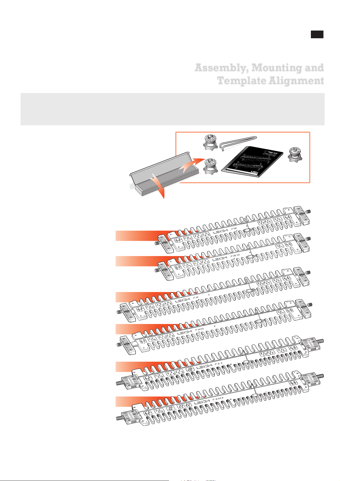
Before you begin mounting the Leigh Finger Joint Template to your Leigh Jig, make sure you have received the model ordered
(Inch or Metric), and all the necessary parts.
1. 1 e7-Bush incl nut (F3 only)
1 e8-Bush incl nut
1 e10-Bush incl nut
1 Pin Wrench
1 User Guide
2. 1 Template “inch” assembly,
or:
1 Template “metric” assembly
If any of these items are missing, please
notify your supplier or Leigh Industries
immediately.
Except for the scale thumbscrews (packed
in a bag attached to the template), your
Leigh F-Template comes fully assembled
and requires only mounting and indexing to your Leigh jig. This procedure is
critical to the accuracy of the finished
joinery, so please follow the mounting
instructions carefully.
F18
F24
F18M
F24M
F3
F3M
Check that you received one of these templates:
e8
e10
e7
(F3/F3M)
1
2
Page 8
2
ASSEMBLY, MOUNTIN G & TEMPLATE ALIGN MENT
Chapter 1 F3, F18 & F24 FINGER JOINT TEMPLATES USERGUIDE
1-1 Super18 & Super24 Jig Owners D-Series jig owners go
straight to 1-6.
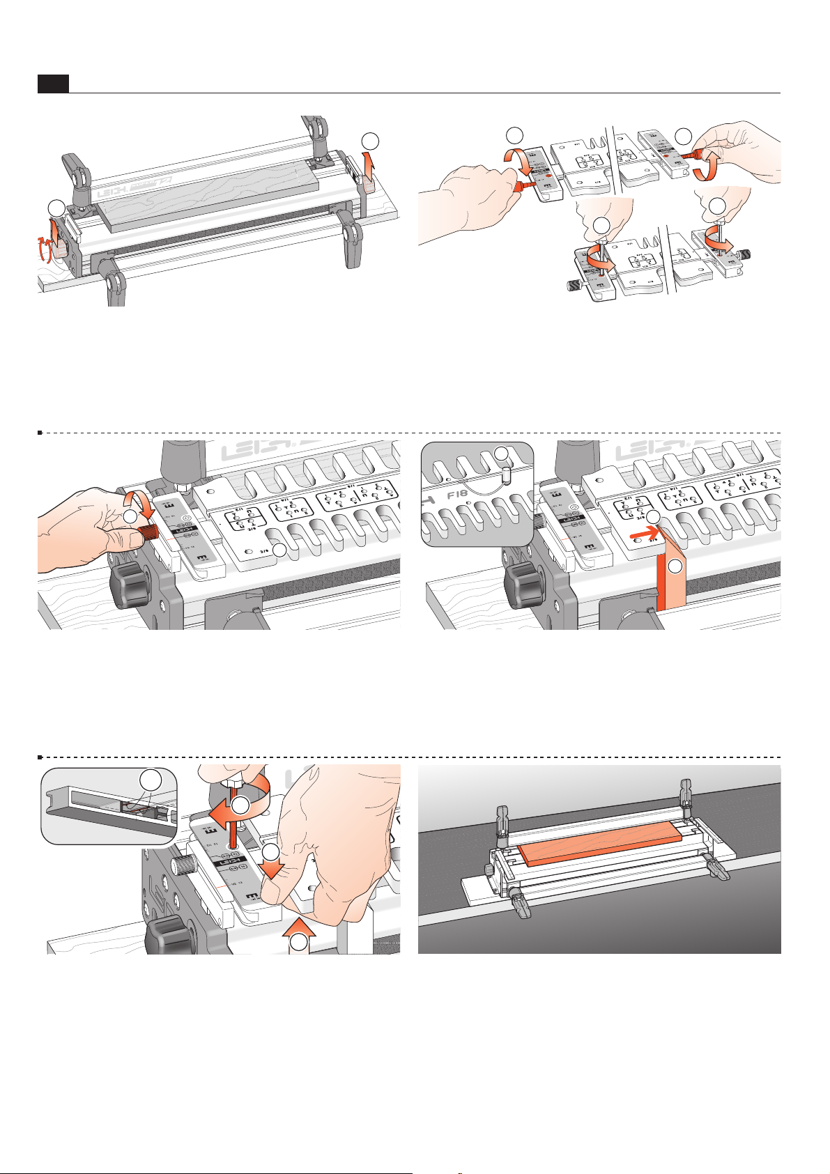
Raise both end support brackets and tighten the support bracket
knobs
~
.
1
1
1-2 Install the two thumbscrews a few turns into the scales ~.
Loosen the scale lock screw
at both ends (by one turn only).
1
1
2
2
1-3 Slide the template onto the support brackets, with the
3
⁄8"[10mm] comb toward you ~ and set on the 3⁄8"[10mm] set-
ting.
Tighten both thumbscrews
.
Do not lower the assembly onto the finger support board.
1
2
1-4 Align the template so that its centre hole aligns with the hole
in the bar and firmly insert the template pin
~
. Angle trim the end
of a straight block and clamp it tight against the left stop; the top
protruding into the last
3
⁄8"[10mm] opening . Move the combined
assembly to the right until the left side of the opening touches the
block
. Taking care to not move the template assembly…
1
2
3
1-5 …pull up on the template bar ~ while pushing down on the scale
to ensure the bar is touching the two registration pads
inside the scale.
Maintain pressure and tighten the scale lock-screw
. Repeat at the other
end. Remove the block and your template is ready to use.
To maintain
correct template alignment, follow this procedure whenever you remove
the scales from the finger assembly.
1
2
4
3
1-6 Mounting F3/F3M to D-Series Jigs
Procedure is the same for Inch and Metric 24" templates.
Make sure your jig is mounted as per its User Guide, and the spacer
board is clamped into position.
Page 9
3
ASSEMBLY, MOUNTIN G & TEMPLATE ALIGN MENT
Chapter 1F3, F18 & F24 FINGER JOINT TEMPLATES USERGUIDE
2 1
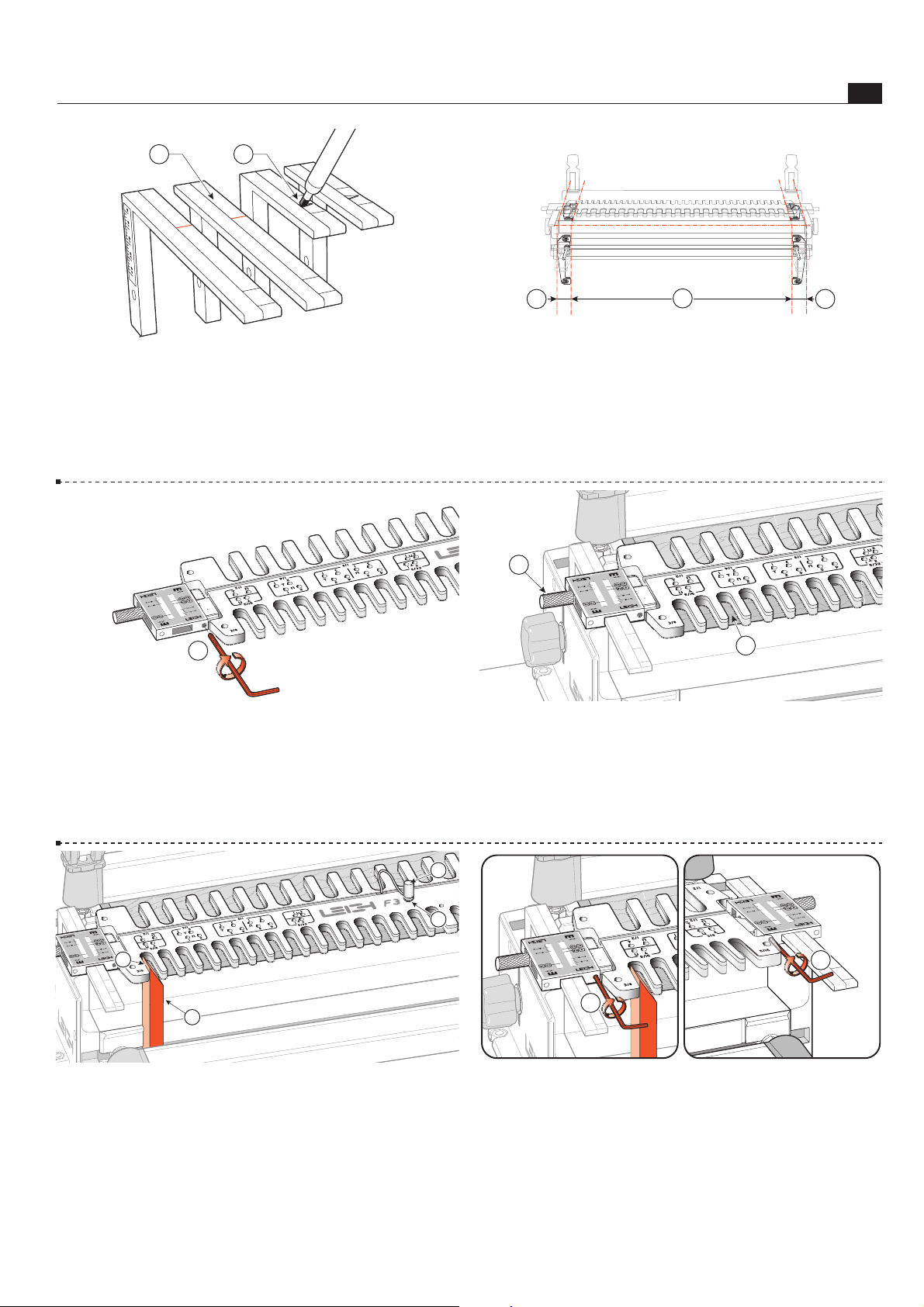
1-7 D1258, D1258R and D3 jig owners: If you already own
the Leigh Mortise and Tenon Attachment, fit its extended support
brackets
~
and use for all finger joint and dovetail procedures. If
not, mark the arrow pointers on the standard support brackets
with a dark felt pen. Some D4 and D4R Jig owners already have
extended brackets. Late model D4R brackets are shorter.
1-8
Before installing the F3/F3M on any 24" D series jig with
adjustable side stops, set and index the stops according to the
jig's user guide. Are the stops 1
1
/2"[38mm] in from each end of
the jig body extrusion
~
and 241/8"[613mm] apart ? If not,
do it now.
D4R jigs have fixed side stops.
2
1 1
1-9 Loosen the scale bar set screw ~, at each end of the tem-
plate.
1
1-10 Slide the template assembly onto the jig support brackets
with the
3
⁄8" & 5⁄16"[10 & 8 mm] combs toward you and lower it
gently onto the jig's spacer board
. Make sure the scale reading
is the same on both scales, then tighten the thumb screws
.
3
4
1-11 Centring the F3 Align the template so that its centre hole ~
aligns with the hole in the bar. Insert the template pin
with a gentle
twist to seat it. Angle trim the end of a straight block; clamp tight
against the left stop and into the first opening
. Move the combined
assembly so the left side of the opening touches the block
. Taking
care to not move the template assembly…
1
3
4
2
1-12 …tighten both scale set screws ~ and . Remove the
block and your Leigh F3 is ready to use. N
1
2
Centring Template on Jig All 24" D series jigs
Page 10

4
ASSEMBLY, MOUNTIN G & TEMPLATE ALIGN MENT
Chapter 1 F3, F18 & F24 FINGER JOINT TEMPLATES USERGUIDE
Page 11
F3, F18 & F24 FINGERJOINT TEMPLATES USERGUIDE
Using Your Template Safely
CHAPTER 2
Safety is not optional.
Read and follow the recommendations in this chapter.
5
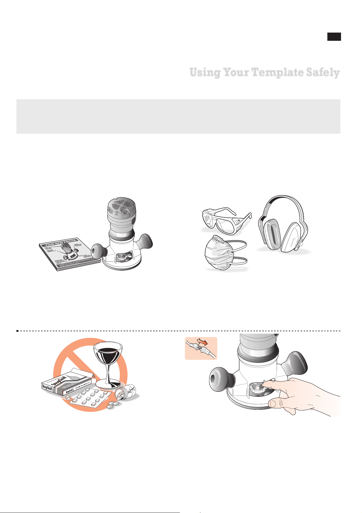
2-4 Always disconnect the power source from the router when
fitting bits or guidebushes, or making adjustments.
Before connecting the router to the power source, make sure the
bit and collet revolve freely in all the areas you plan to rout, and
the bit does not touch the guidebush or jig.
2-1 Read the owner’s manual that came with your router. It is
essential to understand the router manufacturer’s instructions
completely.
2-2 Always wear approved safety glasses.
Protect yourself from harmful dust with a face mask.
Always wear hearing protection.
For complete comfort and convenience, get yourself a Leigh VRS
(Vacuum Router Support) to match your jig model.
2-3
Never drink alcohol or take medications that may cause
drowsiness when you will be operating a router.
Page 12
USING YOUR TEMPLATE SA FELY
6
Chapter 2 F3, F18 & F24 FINGER JOINT TEMPLATES USERGUIDE
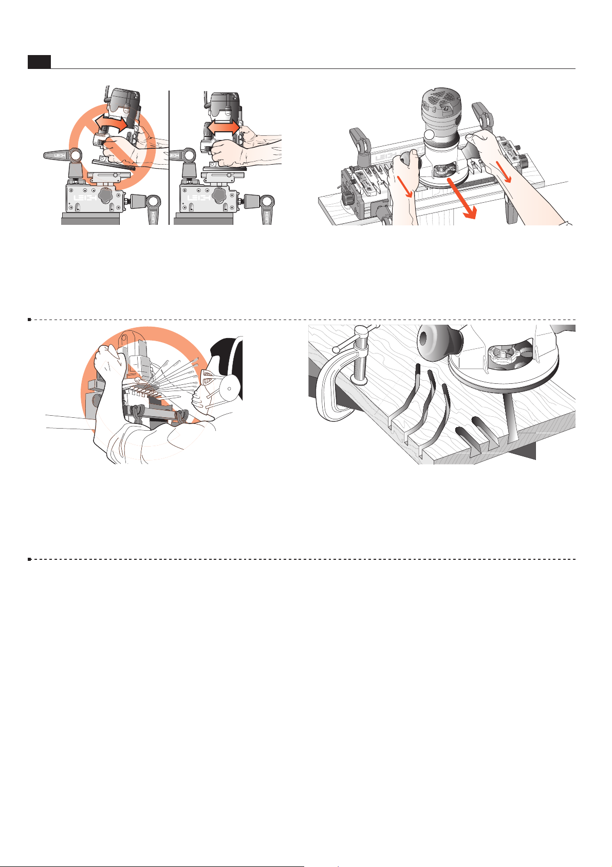
2-5 Do not tilt the router on the jig.
Keep the router flat on the jig assembly.
Note: The optional Leigh VRS attachment prevents router tilting.
2-6 If you insist on removing the router from the jig while it
is still revolving, always pull it straight off the jig horizontally,
and do not raise or lower the router until it is completely clear
of the jig.
1
2-7 Do not rout at face level.
2-8 If you have never used your router before, be sure to follow
the router manufacturer’s instructions for its use. Make plenty
of simple open-face practice cuts without a guidebush before
you try to use the router on the Leigh jig. You must, of course,
always use a guidebush when routing on the Leigh Jig.
N
Page 13
F3, F18 & F24 FINGER JOINT TEMPLATES USERGUIDE
Operation Concept and
Basic Template Functions
CHAPTER 3
7
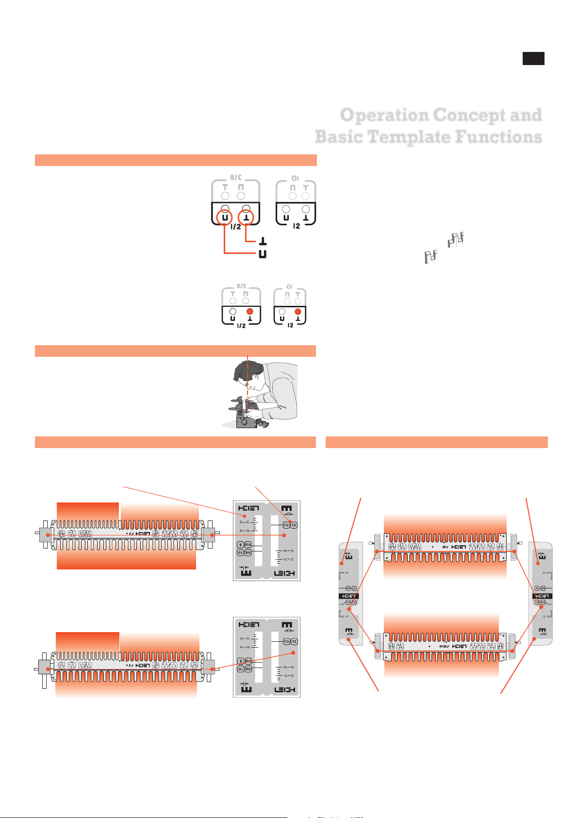
Template Modes
1
/2" Comb
3
/8" Comb
F18 inch
F18M millimetres
12mm Comb
10mm Comb
The active scale is always right
side up and toward you.
The inactive scale is always upside down.
Template pin hole icons denote
the type of joint and edge finish
from each position.
Reading scales from directly overhead
improves setting accuracy.
Square Sockets - tail-board socket at board edge
Square Pins - pin-board pin at board edge
Scale Modes
Throughout the manual, the proper pin location for each step is highlighted with red in
an inset. Only the front (active) pinholes
will be shown.
8mm Comb 10mm Comb
12mm Comb
5
/16" Comb
3
/8" Comb
1
/2" Comb
F3 inch
F3M millimetres
The active scale is always
on the right side of each
scale assembly.
The inactive scale is always on the
left side of each scale assembly
and is upside down.
F3 F18 and F24
Page 14
8
OPERATION CO NCEPTS AND BASIC TEMPLATE FUNCTIONS
Chapter 3 F3, F18 & F24 FINGER JOINT TEMPLATES USERGUIDE
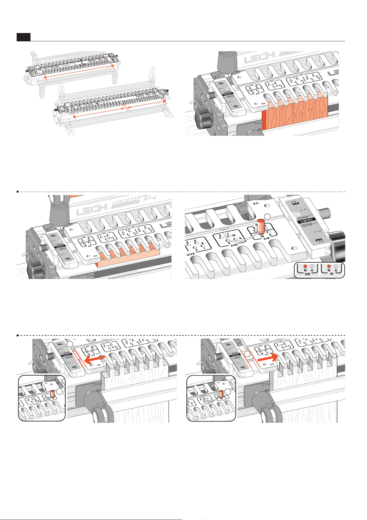
3-1 The active comb (the one you wish to use) is positioned
toward you at the front of the jig. Depending on the Template
model and comb size selected, the active comb may start at either
the right, or left-hand side of the jig. Combs that are the full
width of the template always start at the left side.
F18
F3
3-2 Clamp your work pieces against the front side stop or...
3-3 ...the mating rear side stop, depending on which procedure
is to be used.
3-4 The template control pin engages the template to the template bar using precisely positioned holes
~
. The active template
pin holes are always at the opposite end of the template , out of
the way of the router. Most illustrations will have an inset showing
the correct template pin hole position for the procedure.
1
3-5 Mating joints routed under the same comb have to be offset
to achieve correct joint alignment. On Leigh templates the offset
is achieved by moving the template left or right by half the pitch
of the comb. This movement is controlled by the template pin,
at the other end of the template
~
. Note that the template is close
to the scale .
2
1
3-6 In this illustration, the template is moved to the right by
half the comb pitch and positioned by the template pin
~
to rout
the mating half of the joint in 3-5. Note the increased gap between
the scale and template
. N
2
1
Page 15
F3, F18 & F24 FINGER JOINT TEMPLATES USERGUIDE
Guidebushes and the Unique
Leigh e-Bush
CHAPTER 4
9
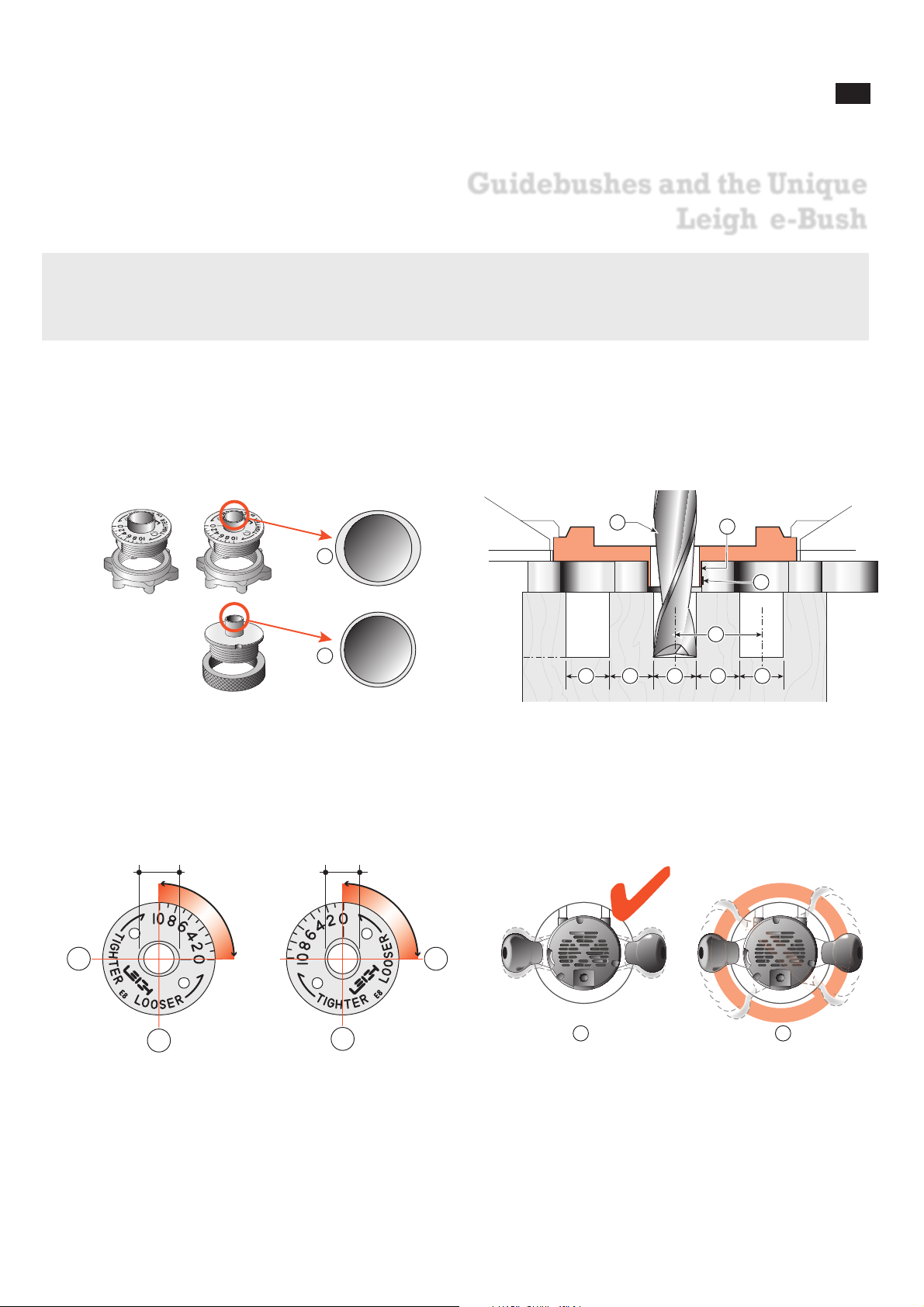
4-1 Unlike plain circular template guidebushes ~, the e-Bush is
elliptical
. This innovation effectively changes the guidebush “active
diameter” when it's rotated, and provides benefits not possible with a
plain round guidebush. The F18 & F24 Templates include two Leigh
e-Bushes*: e-8 for
3
⁄8"[10mm] combs, and e-10 for 1⁄2”[12mm] comb;
the F3 includes those plus the e-7 for
5
⁄16"[8mm] comb.
1
2
4-2 Joint Fit and Joint Pitch Box joints routed with standard
sized straight bits
~
and standard sized guidebushes against
straight guide surfaces
on pitch centres exactly two times the bit
diameter
will guarantee a loose fitting joint. Bits, guidebushes and
templates are manufactured with necessary plus/minus tolerances
and the router will have some degree of run-out, or “wobble”.
1
2
3
4
?? ? ??
1
2
1
2
.500" .480"
1 2
4-3 The e-Bush (e-8 illustrated) fits to the router base or to a
guidebush adaptor in the base. See Appendix I. The ellipse or oval shape
major axis
~
is ~.500", and minor axis ~.480" [12,7 x 12,2mm].
Turning the e-Bush 90 degrees in the router base changes the active
guide size by .020"[,50mm] providing infinite adjustment and recordable settings for perfectly fitting box joints.
4-4 Here’s how it works. In normal use, the operator does not
rotate the router more than a few degrees either way
~
. In fact,
because of potential bit-to-bush eccentricity problems it is advisable to minimize router rotation on jigs
.
*US & CDN Patent Pending. UK Patent No. GB2443974
Page 16
10
GUIDEBUSHE S AND THE UN IQUE LEIGH e-BUSH
Chapter 4 F3, F18 & F24 FINGER JOINT TEMPLATES USERGUIDE
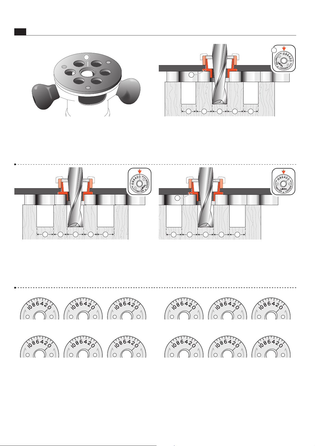
4-7 Turning the e-Bush to zero allows more side-to-side router/
bit movement, and more wood removal, producing larger sockets
and smaller pins, and thus a loose fit.
+ + +- -
4-8 A few trial-and-error test cuts and e-Bush adjustments will
allow you to establish the correct pin and socket sizes for a perfect
fit. Note: One division of the e-Bush changes the joint glue–
line interface by two thousandths of an inch, that is, 0.002" or
0,050mm.
= === =
1
2
4-9 When you have the best joint fit, mark the setting in pencil here. Different wood hardness may require slightly different
settings, so also note the wood species. Use the same bit next
time. N
4-5 Establish the orientation in which you normally hold and
operate the router on the jig. Now, up-end the router in the same
orientation. Make a small scratch line or permanent ink mark on
the router base or e-Bush adaptor at the 12 o’clock position
~
.
1
4-6 With the e-Bush ~ turned to “10” in the base the active
“diameter” is increased, allowing less side-to-side movement, and
resulting in smaller sockets and larger pins. A tight fit! Scale and
movement are exaggerated in this sequence of illustrations.
+ +-- -
1
2
Page 17
F3, F18 & F24 FINGER JOINT TEMPLATES USERGUIDE
Board Width Selection
CHAPTER 5
11
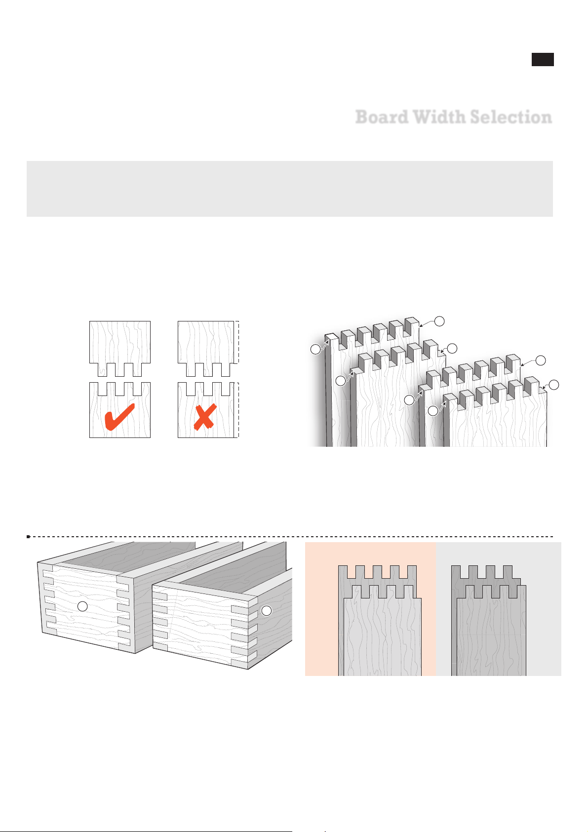
Board widths are determined by the number of fingers you want in your design and whether the joint is symmetrical or
asymmetrical. This chapter makes it easy to determine appropriate widths for the Leigh Finger Joint Templates.
5-1 Board Widths and Joint Symmetry
Unlike the infinitely variable Leigh Dovetail Jig, a fixed template
cannot accommodate any width of board and still produce a neat
and even finish on both side edges of a joint. The boards must be
cut to specific widths, depending on the pitch of the comb.
5-2 Symmetrical joints have pins ~ on both side edges of one
board and sockets
on both side edges of the mating board.
Asymmetrical joints have a pin
on one side edge and a
socket
on the other side edge of each board.
1
1
2
2
4
3
4
3
5-3
Symmetrical joints are essential for half-blind corners ~.
However, ordinary box joints may be asymmetrical and look
okay
.
1
2
5-4
The comb pitches on the Leigh Finger Joint Templates
are all 2 times the bit diameter plus
1
⁄32"[0,75mm], so you
cannot simply use bit diameter to calculate board widths. See the board
width charts on Page 12. For symmetrical square joints use board widths in
red column. For asymmetrical square joints use widths in grey column.
Page 18

12
Board Width Selection
Chapter 5 F3, F18 & F24 FINGER JOINT TEMPLATES USERGUIDE
Symmetrical
Asymmetrical
F18M Template
F24M
F3M Template
12
36
60
85
110
135
160
184
209
234
259
284
308
333
358
383
408
432
457
482
507
531
556
581
606
123456789
1011121314151617181920212223242526272829303132333435363738394041424344454647484950
48
73
98
122
147
172
197
222
246
271
296
321
346
370
395
420
445
469
494
519
544
569
593
618
Symmetrical
Asymmetrical
1
2
3
4
5
6
7
8
9
10
11
12
13
14
15
16
17
18
19
20
21
22
23
24
25
F18M Template
73
122
172
222
271
321
370
420
469
519
569
618
24
98
147
197
246
296
346
395
445
494
544
593
Symmetrical
Asymmetrical
F3M Template
8
24
40
57
74
91
108
124
141
158
175
191
208
225
242
259
123456789
1011121314151617181920212223242526272829303132
32
49
66
82
99
116
133
150
166
183
200
217
233
250
267
Symmetrical
Asymmetrical
1
2
3
4
5
6
7
8
9
10
11
12
13
14
15
16
F3M Template
16
49
82
116
150
183
217
250
66
99
133
166
200
233
267
Symmetrical
Asymmetrical
F18M TemplateF24M Template F3M Template
10
30
50
71
92
113
134
154
175
196
217
238
258
279
300
321
342
362
383
404
425
445
466
487
508
529
549
570
591
612
123456789
101112131415161718192021222324252627282930313233343536373839404142434445464748495051525354555657585960
40
61
82
102
123
144
165
186
206
227
248
269
290
310
331
352
373
393
414
435
456
477
497
518
539
560
581
601
622
Symmetrical
Asymmetrical
1
2
3
4
5
6
7
8
9
10
11
12
13
14
15
16
17
18
19
20
21
22
23
24
25
26
27
28
29
30
F18M TemplateF24M Template
20
61
102
144
186
227
269
310
352
393
435
477
518
560
601
82
123
165
206
248
290
331
373
414
456
497
539
581
622
Symmetrical
Asymmetrical
F3 Template
1
29
⁄
32
3
7
⁄
32
4
17
⁄
32
5
27
⁄
32
7
5
⁄
32
8
15
⁄
32
9
25
⁄
32
1
29
⁄
32
3
7
⁄
32
4
17
⁄
32
5
27
⁄
32
7
5
⁄
32
8
15
⁄
32
9
25
⁄
32
1
2
3
4
5
6
7
8
9
10
11
12
13
14
15
16
2
9
⁄
16
3
7
⁄
8
5
3
⁄
16
6
1
⁄
2
7
13
⁄
16
9
1
⁄
8
10
7
⁄
16
2
9
⁄
16
3
7
⁄
8
5
3
⁄
16
6
1
⁄
2
7
13
⁄
16
9
1
⁄
8
10
7
⁄
16
5/8”
Symmetrical
Asymmetrical
F3 Template
29
⁄
32
1
9
⁄
16
2
7
⁄
32
2
7
⁄
8
3
17
⁄
32
4
3
⁄
16
4
27
⁄
32
5
1
⁄
2
6
5
⁄
32
6
13
⁄
16
7
15
⁄
32
8
1
⁄
8
8
25
⁄
32
9
7
⁄
16
10
3
⁄
32
29
⁄
32
1
9
⁄
16
2
7
⁄
32
2
7
⁄
8
3
17
⁄
32
4
3
⁄
16
4
27
⁄
32
5
1
⁄
2
6
5
⁄
32
6
13
⁄
16
7
15
⁄
32
8
1
⁄
8
8
25
⁄
32
9
7
⁄
16
10
3
⁄
32
123456789
1011121314151617181920212223242526272829303132
1
1
⁄
4
1
29
⁄
32
2
9
⁄
16
3
7
⁄
32
3
7
⁄
8
4
17
⁄
32
5
3
⁄
16
5
27
⁄
32
6
1
⁄
2
7
5
⁄
32
7
13
⁄
16
8
15
⁄
32
9
1
⁄
8
9
25
⁄
32
10
7
⁄
16
1
1
⁄
4
1
29
⁄
32
2
9
⁄
16
3
7
⁄
32
3
7
⁄
8
4
17
⁄
32
5
3
⁄
16
5
27
⁄
32
6
1
⁄
2
7
5
⁄
32
7
13
⁄
16
8
15
⁄
32
9
1
⁄
8
9
25
⁄
32
10
7
⁄
16
5/16”
Symmetrical
Asymmetrical
F18 TemplateF24 Template
1
3
⁄
32
1
7
⁄
8
2
21
⁄
32
3
7
⁄
16
4
7
⁄
32
5
5
25
⁄
32
6
9
⁄
16
7
11
⁄
32
8
1
⁄
8
8
29
⁄
32
9
11
⁄
16
10
15
⁄
32
11
1
⁄
4
12
1
⁄
32
12
13
⁄
16
13
19
⁄
32
14
3
⁄
8
15
5
⁄
32
15
15
⁄
16
16
23
⁄
32
17
1
⁄
2
18
9
⁄
32
19
1
⁄
16
19
27
⁄
32
20
5
⁄
8
21
13
⁄
32
22
3
⁄
16
22
31
⁄
32
23
3
⁄
4
123456789
1011121314151617181920212223242526272829303132333435363738394041424344454647484950515253545556575859606162
1
1
⁄
2
2
9
⁄
32
3
1
⁄
16
3
27
⁄
32
4
5
⁄
8
5
13
⁄
32
6
3
⁄
16
6
31
⁄
32
7
3
⁄
4
8
17
⁄
32
9
5
⁄
16
10
3
⁄
32
10
7
⁄
8
11
21
⁄
32
12
7
⁄
16
13
7
⁄
32
14
14
25
⁄
32
15
9
⁄
16
16
11
⁄
32
17
1
⁄
8
17
29
⁄
32
18
11
⁄
16
19
15
⁄
32
20
1
⁄
4
21
1
⁄
32
21
13
⁄
16
22
19
⁄
32
23
3
⁄
8
24
1
⁄
8
3/8”
Symmetrical
Asymmetrical
F18 TemplateF24 Template
1
2
3
4
5
6
7
8
9
10
11
12
13
14
15
16
17
18
19
20
21
22
23
24
25
26
27
28
29
30
31
2
9
⁄
32
3
27
⁄
32
5
13
⁄
32
6
31
⁄
32
8
17
⁄
32
10
3
⁄
32
11
21
⁄
32
13
7
⁄
32
14
25
⁄
32
16
11
⁄
32
17
29
⁄
32
19
15
⁄
32
21
1
⁄
32
22
19
⁄
32
24
1
⁄
8
3
1
⁄
16
4
5
⁄
8
6
3
⁄
16
7
3
⁄
4
9
5
⁄
16
10
7
⁄
8
12
7
⁄
16
14
15
9
⁄
16
17
1
⁄
8
18
11
⁄
16
20
1
⁄
4
21
13
⁄
16
23
3
⁄
8
3/4”
Symmetrical
Asymmetrical
F18 TemplateF3 & F24 Template
1
15
⁄
32
2
1
⁄
2
3
17
⁄
32
4
9
⁄
16
5
19
⁄
32
6
5
⁄
8
7
21
⁄
32
8
11
⁄
16
9
23
⁄
32
10
3
⁄
4
11
25
⁄
32
12
13
⁄
16
13
27
⁄
32
14
7
⁄
8
15
29
⁄
32
16
15
⁄
16
17
31
⁄
32
19
20
1
⁄
32
21
1
⁄
16
22
3
⁄
32
23
1
⁄
8
123456789
10111213141516171819202122232425262728293031323334353637383940414243444546
2
3
1
⁄
32
4
1
⁄
16
5
3
⁄
32
6
1
⁄
8
7
5
⁄
32
8
3
⁄
16
9
7
⁄
32
10
1⁄4
11
9
⁄
32
12
5
⁄
16
13
11
⁄
32
14
3
⁄
8
15
13
⁄
32
16
7
⁄
16
17
15
⁄
32
18
1
⁄
2
19
17
⁄
32
20
9
⁄
16
21
19
⁄
32
22
5
⁄
8
23
21
⁄
32
1/2”
Symmetrical
Asymmetrical
1
2
3
4
5
6
7
8
9
10
11
12
13
14
15
16
17
18
19
20
21
22
23
F18 TemplateF3 & F24 Template
3
1
⁄
32
5
3
⁄
32
7
5
⁄
32
9
7
⁄
32
11
9
⁄
32
13
11
⁄
32
15
13
⁄
32
17
15
⁄
32
19
17
⁄
32
21
19
⁄
32
23
21
⁄
32
4
1
⁄
16
6
1
⁄
8
8
3
⁄
16
10
1⁄4
12
5
⁄
16
14
3
⁄
8
16
7
⁄
16
18
1
⁄
2
20
9
⁄
16
22
5
⁄
8
1”
F3 Template
F3 Template
F3M TemplateF24M
F3M Template
Board Width - INCHES Board Width - MILLIMETRES
Note:
Symmetrical joints: use red column.
Asymmetrical joints: use grey column
Numbers in white column are number of board sockets and pins
 Loading...