

Page 1

LEIGH USER GUIDE
LEIGH USER GUIDE
Joining Tradition with Today
Finger Joint Template
Finger Joint Template
Page 2
ii
Your New Leigh Fingerjoint Template
You now own a unique finger jointing system.
The Leigh F1 template and Variable Guidebush
System (VGS) will help you rout a variety of
square and rounded finger or box joints with
unique adjustment for precise tightness of fit.
“Finger” and “Box”: Both words are used universally to title this simple but strong joint.
As the first machine-made joint, it’s old enough
to be called antique, so we have been even-handed in using both terms thoughout this guide.
We recommend that you first mount the F1 on
your D Series Leigh Jig carefully following the
instructions in the first section of the manual.
Important: Inches and Millimetres
Leigh makes the F1 attachment in two models;
inch or metric. Text and illustrations in this
Leigh English-language user guide indicate
dimensions in both inches and millimetres.
Dimensions are indicated in text and illustrations with “inches” first, followed by “millimetres” in square parentheses.
Example:
3
⁄4" x 51⁄2" x 8" or longer [20 x 140 x 200mm]
Do not be concerned if the inch/millimetre equivalents are not always exact. Just use the dimen-
sions which apply to your jig.
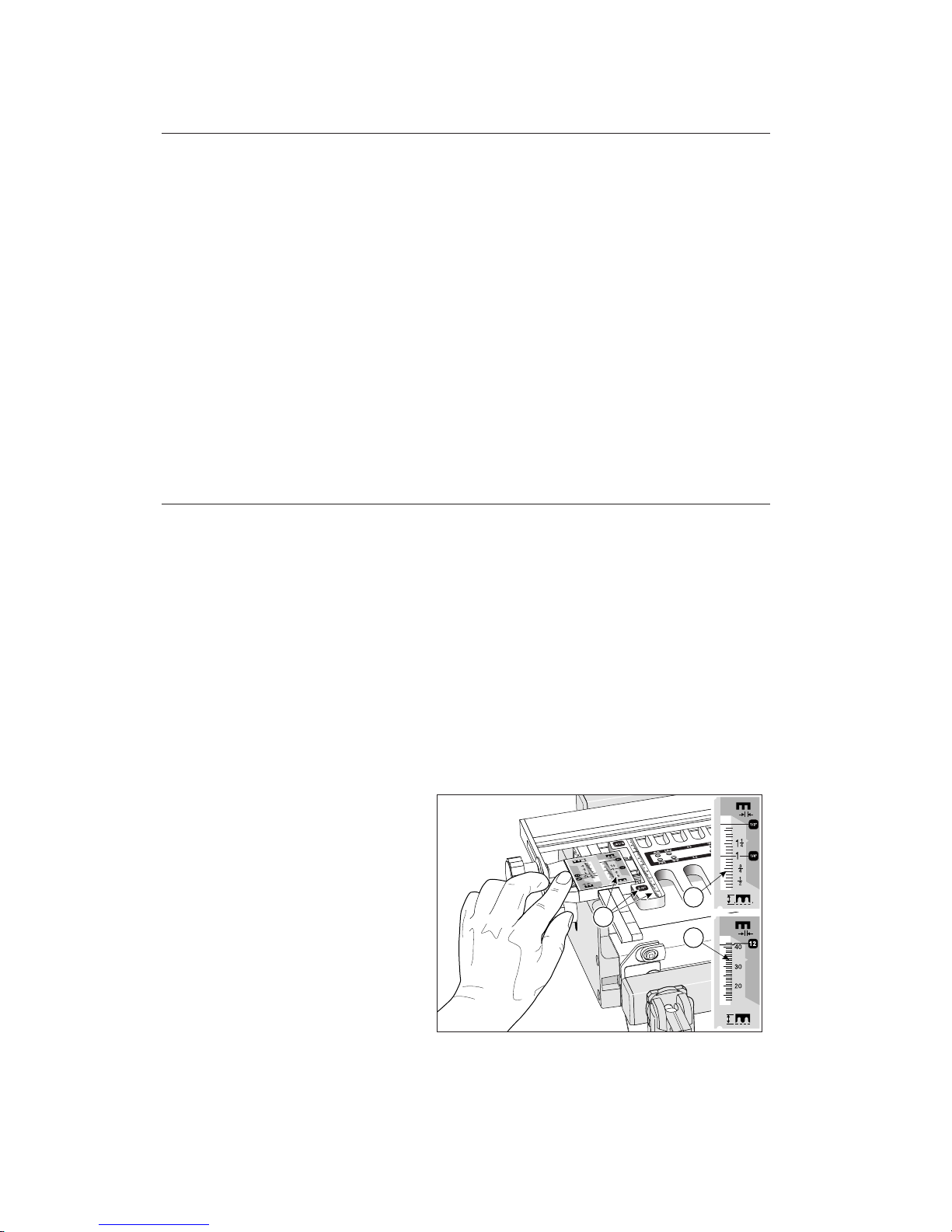
Where finger assembly or template scales
overlay an illustration, the “inches” scale
➀
will be at the top, the “millimetres” scale
➁
will be at the bottom. Only the right “active”
half of the scales are illustrated. For clarity, setting positions are indicated in the
manual with a red line. On the jig, the
lines are black.
General views of the template will show
inch markings
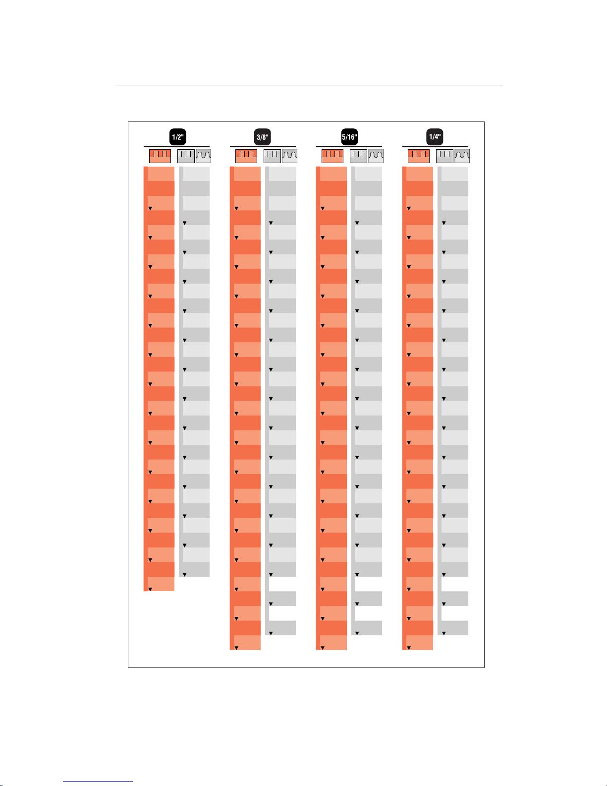
➂
.
Then read the rest of the manual, following
along with the basic functions, before you try
to do any actual joinery routing. By all means,
cut a few practice joints in scrap boards before
you use the F1 to rout a precious hardwood
workpiece.
If you have any questions that are not answered
in the manual, please call the most convenient
Leigh customer support line *.
*See Appendix IV – Customer Support
1
3
2
Page 3

iii
Glossary of Symbols............................................................................................................iv
CONTENTS
CHAPTER1- Assembly, Mounting and Template Alignment........................1
CHAPTER2-Using Your Template Safely..........................................................15
CHAPTER3-Operation Concepts and Basic Template Functions..........21
CHAPTER4-The Variable Guidebush System (VGS)..............................27
CHAPTER5-Board Width Selection....................................................................33
CHAPTER6-Box Joint Procedures ......................................................................39
CHAPTER7-Rounded Half-Blind Finger Joint Procedures....................49
CHAPTER8-Square Half-Blind Box Joint Procedures............................57
CHAPTER9-Rabbetted Half-Blind Finger Joints............................................63
CHAPTER10- Small Box Joints ................................................................................67
CHAPTER11- Wider Box Joints ......................................................................79
CHAPTER12- Hints and Tips............................................................................85
Appendix I - Variable Guidebush Selection......................................................91
Appendix II - Cutter Selection and Joint Specification..................................97
Appendix III - Template Parts List ......................................................101
Appendix IV - Customer Support......................................................................105
Page 4

iv
GLOSSARY OF SYMBOLS
Glossary of Symbols
The Leigh F1 template can be in one of only
two modes with either the
1
⁄2"and 1⁄4" [12mm]
comb sizes to the front or the
3
⁄8" and 5⁄16"
[10 and 8mm] comb sizes to the front.
Scale Icons
This icon on the green scale
background indicates the active
scale for square box joints.
This icon on the gray scale
background indicates the active
scale for rounded finger joints.
Template Icons
Indicates the two template positions
for square box joints
Indicates the two template positions
for rounded finger joints
How to Read the Symbols
To help you understand the instructions and
illustrations in this manual, we have used a
number of international symbols, plus a few
special ones of our own. They are all explained
below. You needn’t worry about memorizing
these symbols now, because they are repeated
quite frequently in the manual, and you will
soon get used to them.
Page 5
v
The following symbols indicate:
l
Left side of item (drawer, box,
case, etc.)
r
Right side of item
t
Top of item
b
Bottom of item
e
This edge against side stop
f
This edge against side stop
As above, other side of board
Sawcut allowance
Caution: use special care for this
operation
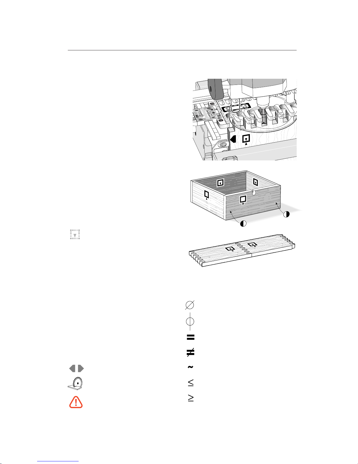
Which Way Round Should the Board Go?
Most joinery done on the Leigh jig is for casework (i.e., boxes, cabinets, drawers, chests and
so on) so in nearly all the illustrations we have
indicated which side of the board shows
outwards when it is in the jig, eg. in this figure the inside face
i
of the tail board is
away from the jig.
o
This indicates the side of the board that
will face outward on the finished
project.
i
This indicates the side of the board that
will face inward on the finished project.
j
This indicates a side that can face
either inward or outward on the
finished project
Dotted line icons are on the other side of
the board.
➀➁➂
Reference in text
Diameter
Centreline of board or layout
Equals
Does not equal
Approximately
Less than or equal to
Greater than or equal to
Page 6

GLOSSARY OF SYMBOLS
vi
Page 7

Assembly, Mounting and
Template Alignment
CHAPTER 1
Page 8

Chapter 1 F1 User Guide
Assembly and Mounting
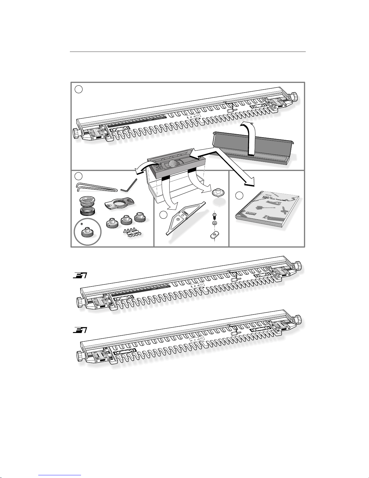
Before you begin mounting the Leigh F1 finger
joint template to your D Series jig, make sure you
have received the model ordered (Inch or Metric),
and all the necessary parts.
1. 1 complete F1 template “inch” assembly
or
1 complete F1 template “metric” assembly
2. Variable Guidebush System consisting of:
1 storage box
1 pin wrench
1 hex key (Allen wrench)
1 700V holder with lock ring
1 701V holder
1 709V bush* with F1 “inch” only
1 711V bush
1 713V bush
1 716V bush
6 bush nylon plugs (on one tree)
3. 1 locator
1 screw
1 washer
1 nut (for D1258-24 jigs only)
1 dial knob
4. 1 user guide
If any of these items are missing, please notify your supplier or Leigh Industries immediately.
Your Leigh F1 comes fully assembled and requires
only mounting and indexing to your Leigh jig.
This procedure is critical to the accuracy of the
finished joinery, so please follow the mounting
instructions carefully.
A SSEMBLY, MOUNTING AND TEMPLATE ALIGNMENT
2
Page 9
1
2
3
4
Illustration shows F1 "Inch". See below for your template model.
Check that you have received one of the templates shown below:
“Inch”
“Millimetres”
3
Page 10
1-1
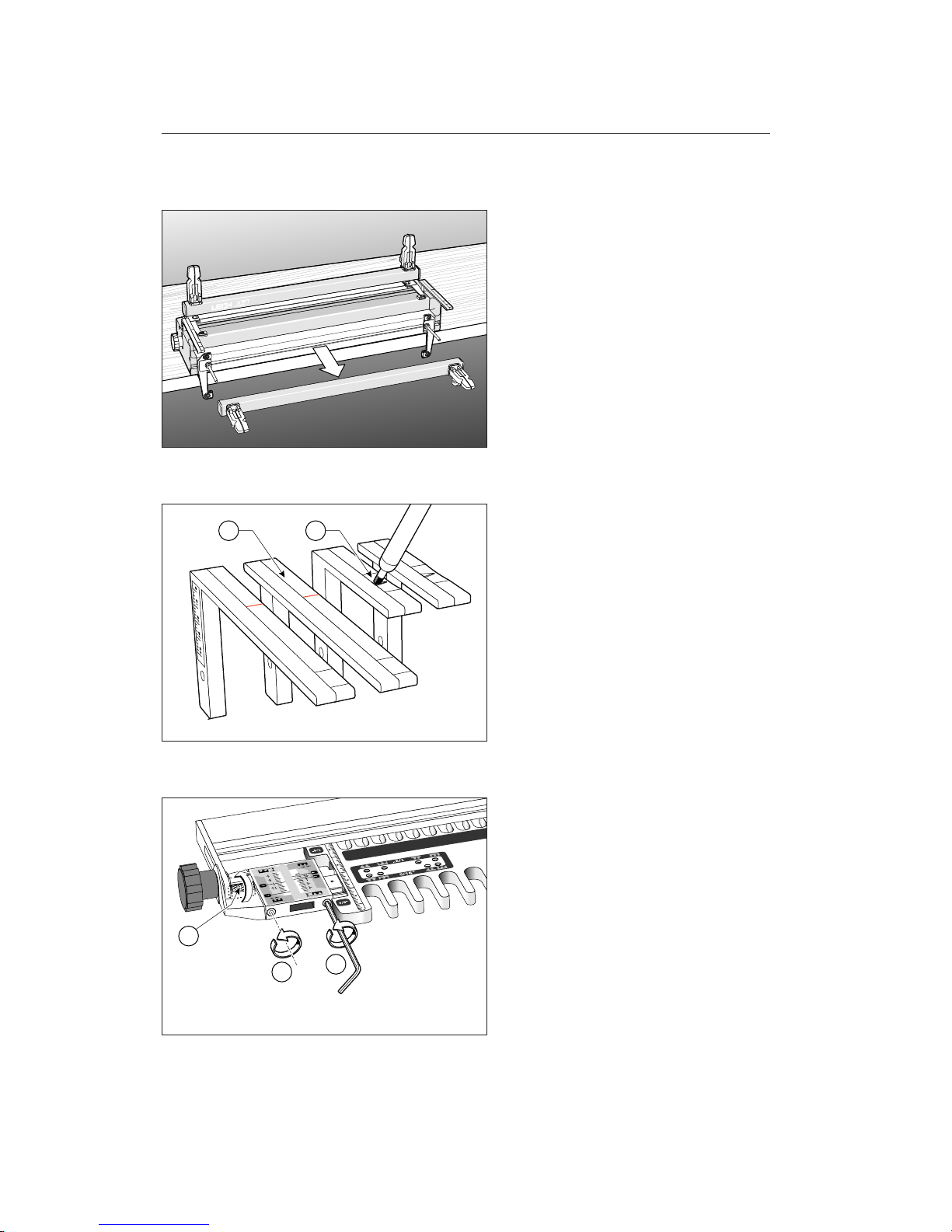
Mount the 24"[610mm] D Series dovetail
jig firmly to a bench as per that jig
’
s instructions. Remove the dovetail finger assembly, front clamp bar and springs.
1-2
D1258, D1258R and D3 jig owners:
If you already own the Leigh Mortise and
Tenon Attachment, fit the extended support brackets
➀
of this attachment and use
for all finger jointing and dovetailing
procedures. If not, mark the tops of the
arrow pointers on the standard support
brackets
➁
with a dark felt pen.
D4 Jig owners already have the extended
brackets.
1-3
Loosen the two scale bar set screws ➀, the
two fence bracket screws
➁
, and two scale
thumb screws
➂
at both ends of the tem-
plate.
21
3
1
2
A SSEMBLY, MOUNTING AND TEMPLATE ALIGNMENT
Chapter 1
4
Chapter 1 F1 User Guide
Page 11
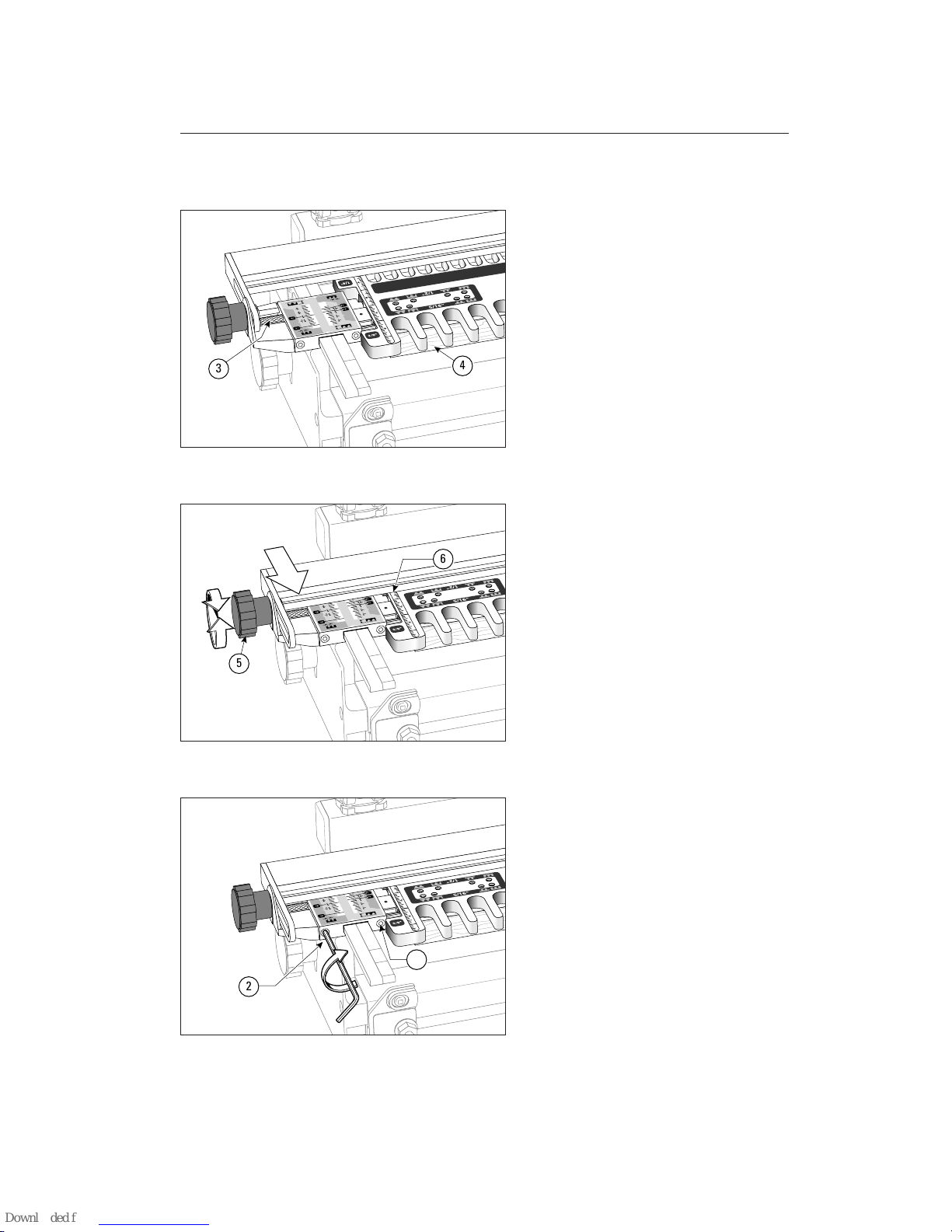
1-4
Slide the template assembly onto the jig
support brackets with the
3
⁄8
" and
5
⁄16
"
[10 and 8mm] combs toward you and lower
it gently onto a
3
⁄4
"[20mm] thick spacer
board
➃
(A piece of3⁄4
"x 5
1
⁄2
"[20x150mm]
about 23"[580mm] long). Make sure the
scale reading is the same on both scales, say
on the 1"[25mm] mark, then tighten the
thumb screws
➂
.
1-5
Loosen the fence knobs ➄and move the
fence on the template toward you as far forward as possible and with the fence scale
reading the same at both ends
➅
. Then
tighten the fence knobs
➄
.
1-6
Tighten the scale bracket screws ➁, but do
not tighten the scale bar
➀
screws yet.
3
4
5
6
2
1
5
Page 12
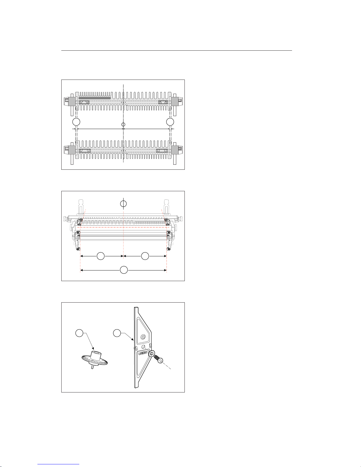
1-7
To ensure that you produce the precise joints
the Leigh F1 template was designed to provide, the following procedures must be carefully followed:
First, the template bar and template must
be centred exactly between the two scale
assemblies
➀
and…
1-8
…then, the side stops must be positioned
precisely 24
1
⁄
8"[613mm] apart
➁
and equidis-
tant from the centreline
➂
. Here's how to
do it.
1-9
On the logical assumption that you do not
have access to a 25"[650mm] dial calliper,
Leigh provides tools that fulfil the same
function.
The dial knob
➀
has a tapered axle and a
cam shaped hub, and acts as a micrometer
to centre the template bar between the scales.
Each minor dial increment equals
0.0015"[0,04mm] of template movement.
The part
➁
is the side stop locator.
====
1 1
Inch
Metric
3
2
3
1 2
A SSEMBLY, MOUNTING AND TEMPLATE ALIGNMENT
Chapter 1
6
Chapter 1 F1 User Guide
Page 13
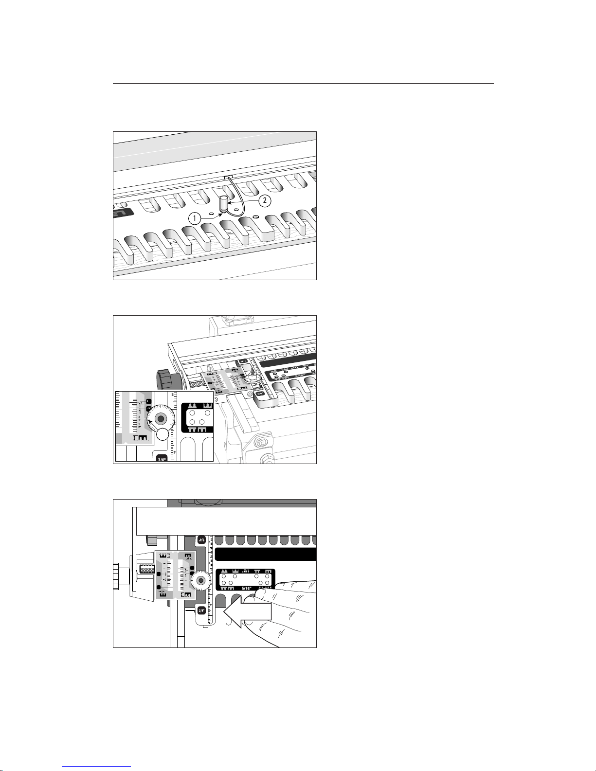
1-10
Align the template so that the template’s
centre hole
➀
lines up with the hole in the
bar (it will only align with one hole in the
bar) and insert the template pin
➁
. Gently
twist and push the tapered pin into the hole
until it is fully seated. The template is now
perfectly centred on its bar, but now we
must centre the bar in the scales.
Note: Discard the shipping plug from the
centre hole.
1-11
Place the dial knob in the hole in the lefthand end of the template bar next to the
scale. Align the No.2 mark on the dial with
the small pointer on the grey scale
➀
.
1-12
Gently move the complete template and
bar assembly to the left until the (cam) hub
of the dial knob stops against the scale body.
;;;
2
1
1
3
4
1
2
1
4
3
4
1
2
1
4
1/4"
1/2"
5/16"
3/8"
4
2
0
2
4
7
3/8"
1
4
0
5/16"
2
3
2
4
1
2
4
4
Page 14
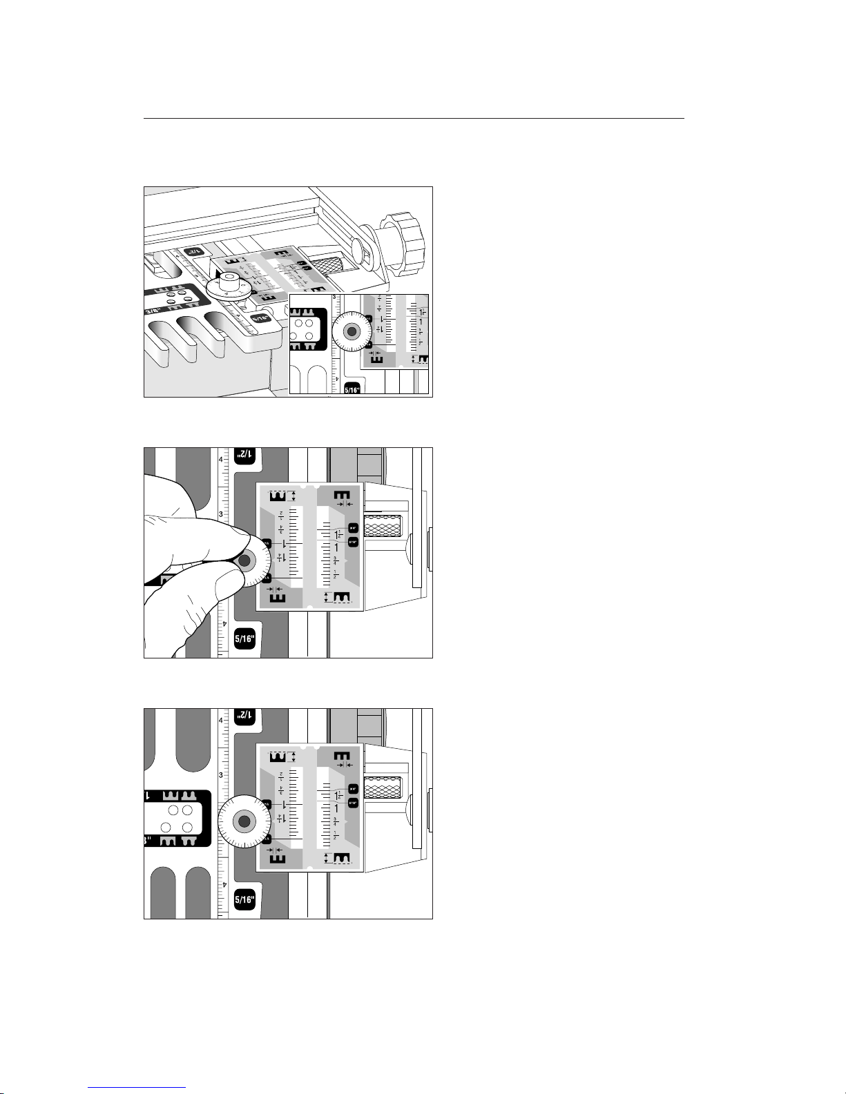
1-13
Taking care not to turn the knob or move
the template/bar assembly, carefully pull
the dial knob directly out of the bar. Insert
the dial knob into the hole in the righthand end of the bar with the grey scale
pointer pointing to the zero mark on the
dial knob.
1-14
Slowly turn the dial knob (either way) until
you feel the cam surface of the hub lightly touch the scale casting. It should touch
before the “5” indicator mark passes the
scale pointer. Note the dial reading, e.g. 4
in this illustration. If the dial knob hub
does not touch the scale casting, repeat
steps 1-11 to 1-14 but start at a higher dial
number in step 1-11.
1-15
Turn the dial back to the average of the dial
settings at the left and right-hand ends. In
this example (2+4)÷2 =3.
4
2
0
2
4
4
2
0
2
4
A SSEMBLY, MOUNTING AND TEMPLATE ALIGNMENT
Chapter 1
8
Chapter 1 F1 User Guide
4
2
0
4
2
Page 15
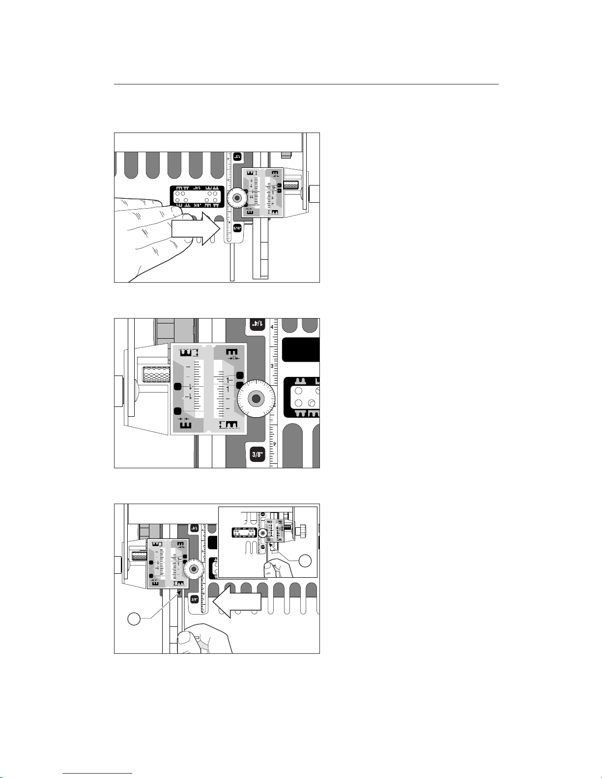
1-16
Push the template/bar assembly to the right
until it stops with the dial knob’s cam hub
against the scale.
1-17
The template/bar should now be centred
on the jig. Double check by pulling the dial
knob directly out of the right-hand gap,
inserting it back into the left-hand gap with
the “0” mark next to the grey scale pointer. Turn the knob and verify that the hub
cam touches the scale casting at the same
reading as on the right-hand end (i.e., at
“3” in this example). Don’t fret over an odd
increment; remember, each is only
0.0015"[0,04mm] of template movement.
1-18
When the dial knob’s hub cam touches the
scale casting at the same dial reading at both
ends of the template, the template/bar
assembly is centred on the jig. With light
pressure from the template holding the dial
knob against the scale casting at the correct reading, tighten first one scale bar screw
➀
, then the scale screw at the other end ➁.
4
2
0
2
4
3
4
1
2
1
4
3
4
1
2
1
4
1/4"
1/2"
5/16"
3/8"
4
2
0
2
4
3
4
1
2
1
4
3
4
1
2
1
4
1/4"
1/2"
5/16"
3/8"
4
2
0
2
4
1
2
9
4
4
2
2
0
Page 16
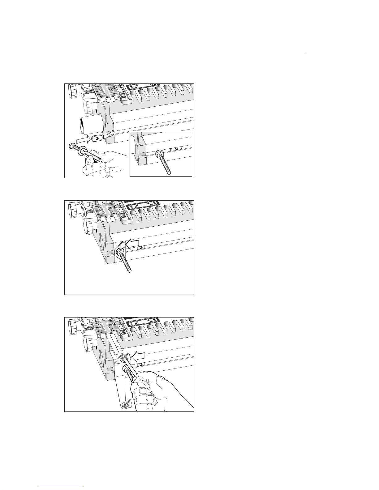
1-19
D1258 jigs only: Loosen both front side
stop bolts. Remove the left-hand side stop
assembly and slide the small tab nut from
the centring kit into the front extrusion.
Replace the left-hand side stop assembly,
but leave it loose. The tab nut will remain
in the extrusion after assembly.
1-20
D1258R and D3 jigs: Loosen both front
side stop bolts and move both of the assemblies slightly out from their original positions.
1-21
D4 jig: Loosen the front side stop bumpers,
move them outward from the centre of the
jig, and leave them loose.
A SSEMBLY, MOUNTING AND TEMPLATE ALIGNMENT
Chapter 1
10
Chapter 1 F1 User Guide
Page 17
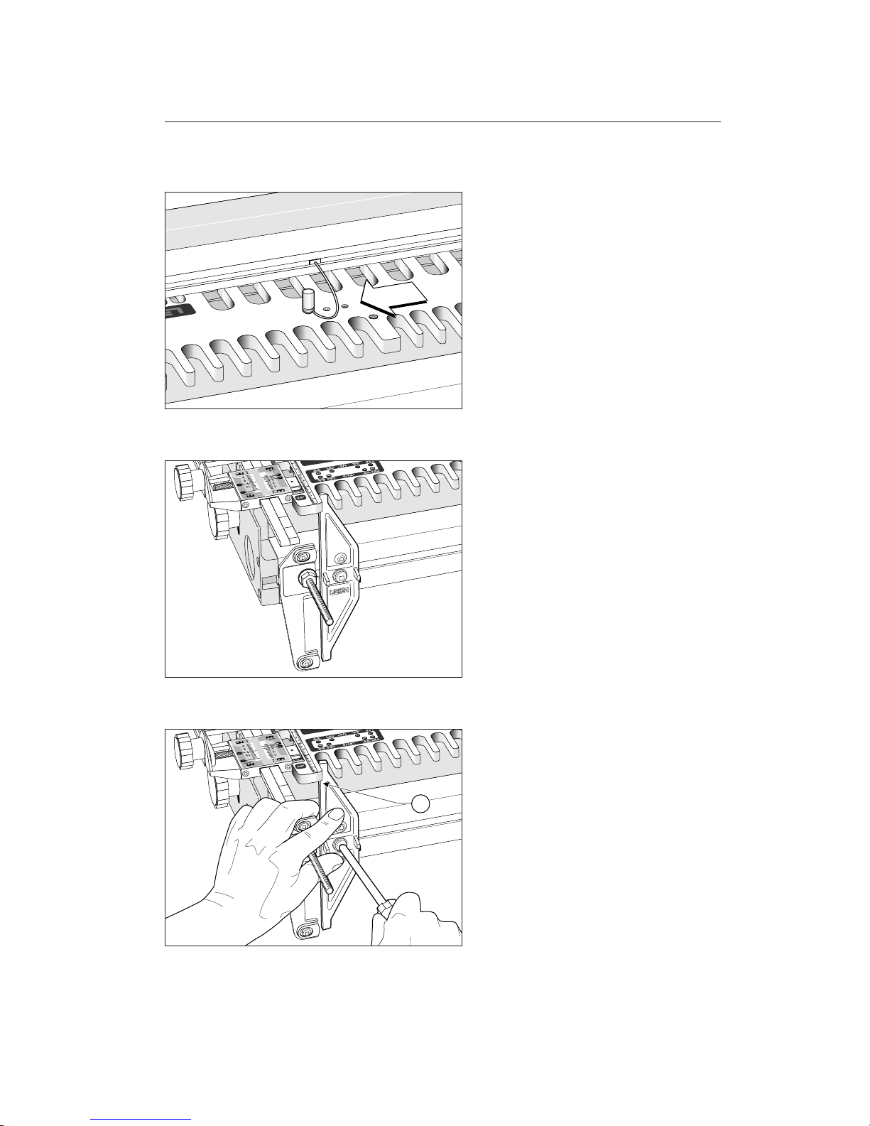
1-22
Remove the template pin from the centre
hole, move the template slightly to the left
and align the left hand hole with its matching bar hole. Insert the template pin, again
gently pushing and twisting until it is fully
seated.
1-23
With the screw and washer from the locator kit, lightly screw the side stop locator
to the front extrusion with the Leigh logo
below the screw and the upper tip of the
locator projecting up through the last opening in the
3
⁄8"[10mm] comb. Do not tighten yet: the locator must be movable. D1258
owners will use the tab nut, D1258R, D3
and D4 jig owners will use the angled side
stop square nuts already in the extrusion
slot to attach the screw.
1-24
With the projections on the rear of the locator resting on the bottom edge of the extrusion T slot to act as a try square, slide the
locator to the left until the outside edge of
the upper tip just touches the outside of
the
3
⁄8"[10mm] comb’s leftmost opening➀.
Holding the locator square, tighten the
screw snugly using your Leigh square drive
screwdriver. Note: Your Leigh square drive
screwdriver is one size too small for this
screw but it's okay for this one time use.
1
11
Page 18
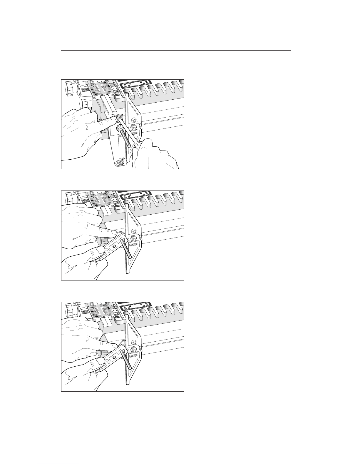
1-25
D4 Jig: Move the side stop bumpers against
the locator and tighten them firmly. Remove
the locator from the front extrusion.
1-26
D1258 Jig: Move the washer type side stop
to touch the locator, then tighten the nut.
Remove the locator from the front extrusion.
1-27
D1258R and D3 Jigs: Move the plastic
side stop to touch the locator and hold firmly square while tightening the nut. Remove
the locator from the front extrusion.
A SSEMBLY, MOUNTING AND TEMPLATE ALIGNMENT
Chapter 1
12
Chapter 1 F1 User Guide
Page 19
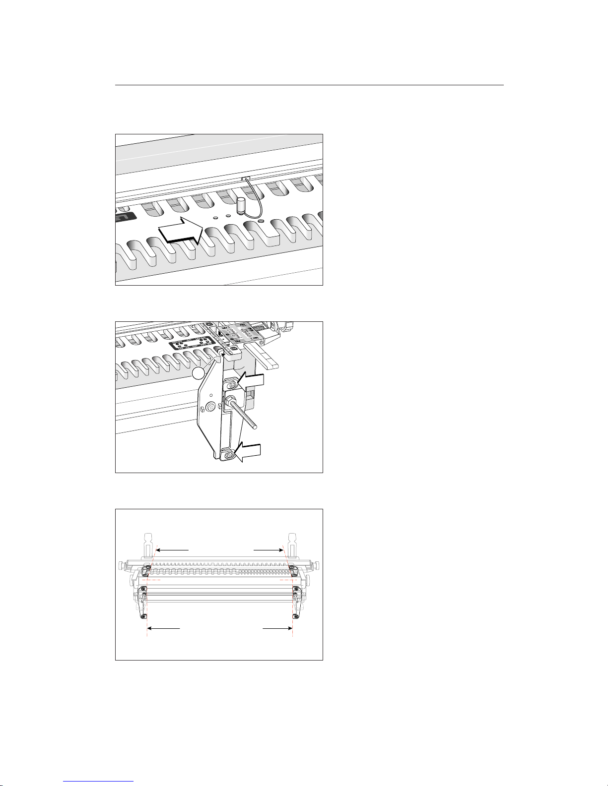
1-28
Remove the template pin, slide the template a little to the right, and align the righthand alignment hole with the matching
hole in the bar. Place the template pin in
this hole, gently turning it until it is fully
seated.
1-29
Reverse the locator to the right-hand end
of the jig, with the Leigh logo below the
screw, facing toward the jig. Lightly screw
it onto the extrusion. The locator’s upper
tip projects up through the last opening in
the
5
⁄16"[8mm] comb, with the outside edge
of the upper tip just touching the outside
of the comb’s opening
➀
. Repeat steps 124 to 1-27 but mirrored for this right-hand
end of the jig. Store the dial knob and locator kit in the VGS box liner for future use.
1-30
Align the rear side stops to the front stops
using the method described in your dovetail jig body assembly instructions. Now
that this side stop indexing is complete,
your jig is set up for all Leigh attachments.
1
13
Page 20
1-31
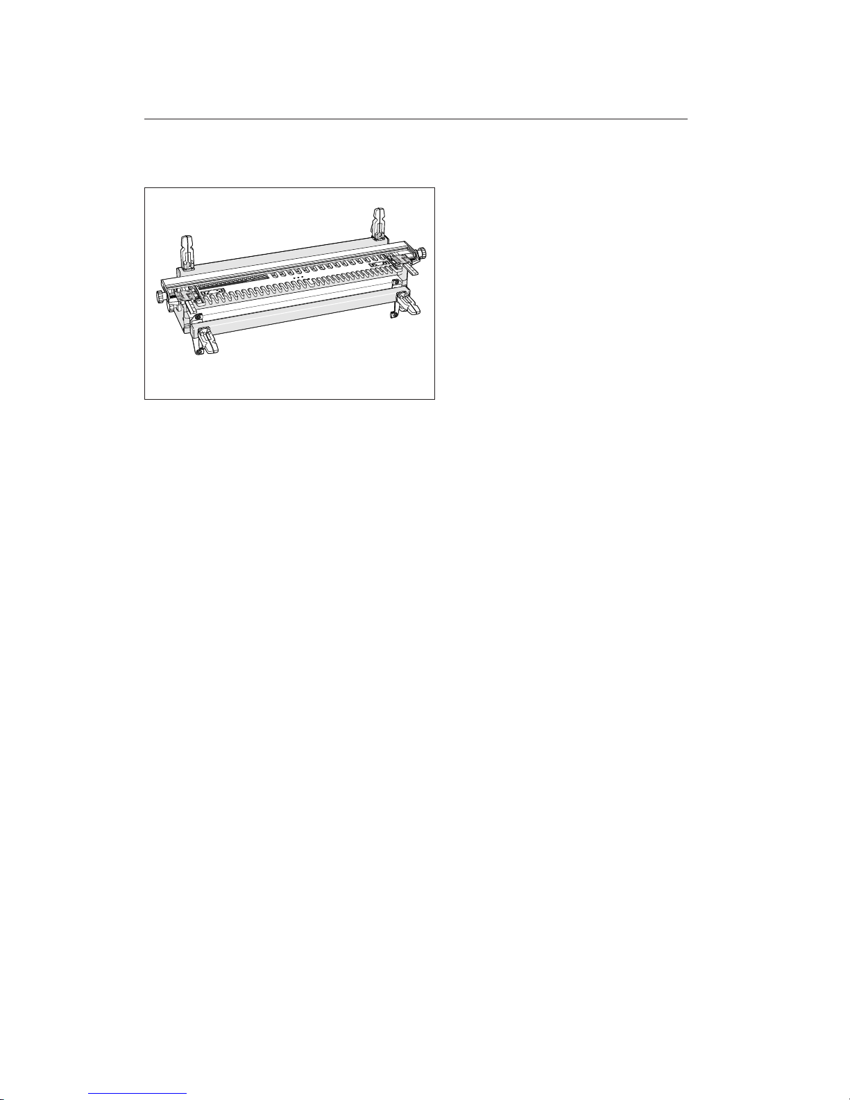
Replace the front clamp bar and knobs or
cam clamps. Your Leigh F1 Template is now
ready for use.
A SSEMBLY, MOUNTING AND TEMPLATE ALIGNMENT
14
Chapter 1 F1 User Guide
Page 21
Using Your Template Safely
CHAPTER 2
Page 22

Chapter 2 F1 User Guide
USING YOUR TEMPLATE SAFELY
16
Chapter Foreword
Safety is not optional.
Read and follow the recommendations in
this chapter.
Page 23
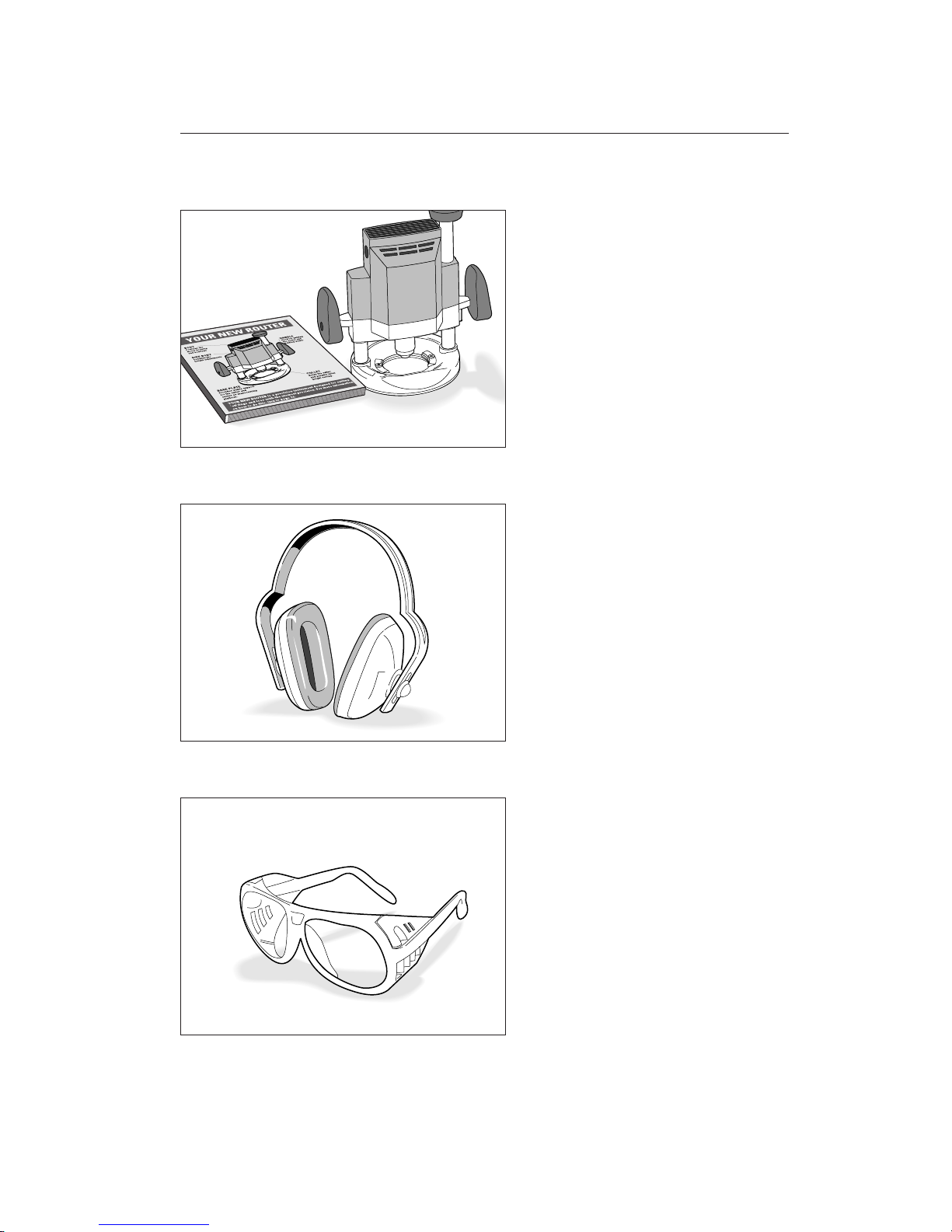
2-1
Read the owner’s manual that came with
your router. It is essential to understand
the router manufacturer’s instructions
completely.
2-2
Always wear hearing protection when using
a router.
2-3
Always wear approved safety glasses when
using a router.
17
Page 24
Chapter 2 F1 User Guide
2-4
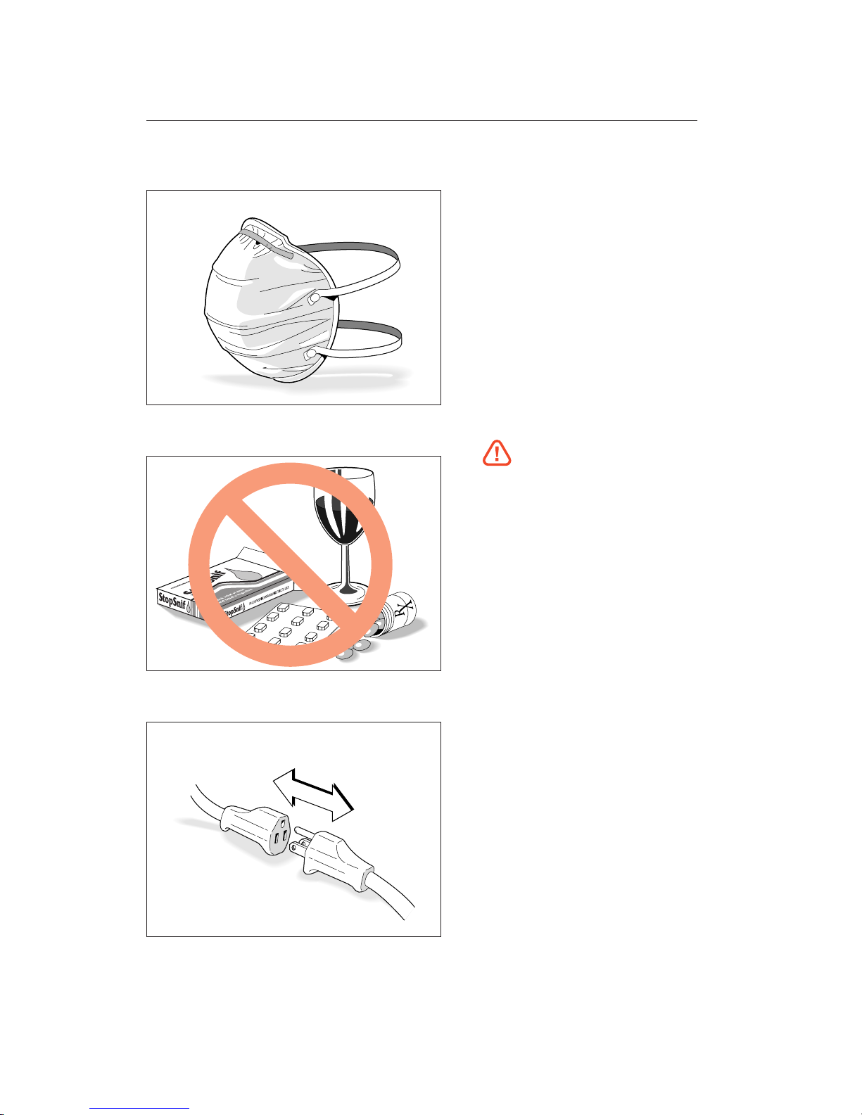
Protect yourself from harmful dust by wearing a face mask.
2-5
Never drink alcohol or take medications
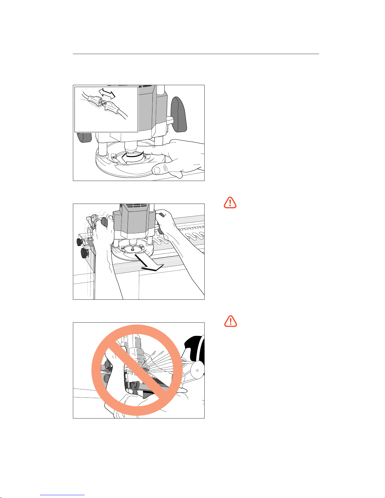
that may cause drowsiness when you will
be operating a router.
2-6
Always disconnect the power source from
the router when fitting cutters or guidebushes, or making adjustments.
USING YOUR TEMPLATE SAFELY
18
Page 25
2-7
Before connecting the router to the power
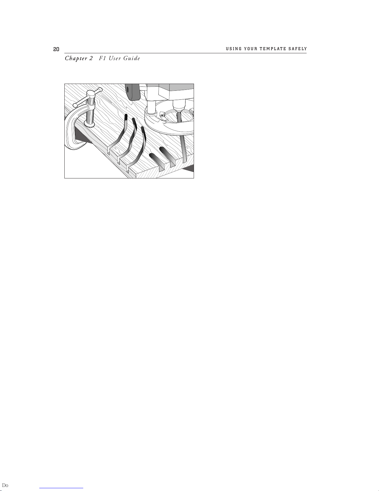
source, make sure the cutter and collet
revolve freely in all the areas you plan to
rout, and the cutter does not touch the
guidebush or jig.
2-8
If you insist on removing the router from
the template while it is still revolving, always
pull it straight off the jig horizontally, and
do not raise or lower the router until it
is completely clear of the template.
2-9
Do not rout at face level.
19
Page 26
2-10
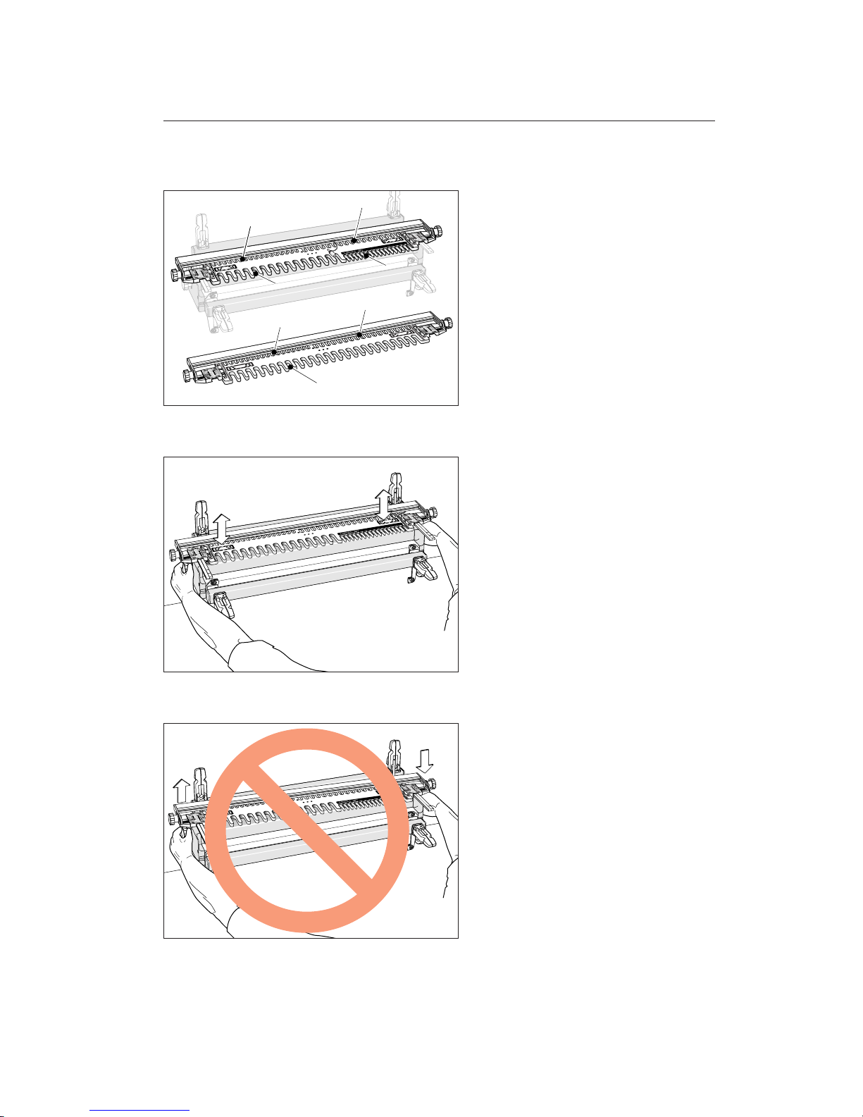
If you have never used your router before,
be sure to follow the router manufacturer’s instructions for its use. Make plenty
of simple open-face practice cuts without
a guidebush before you try to use the router
on the Leigh Template. You must, of course,
always use a guidebush when routing on
the Leigh Template.
USING YOUR TEMPLATE SAFELY
20
Chapter 2 F1 User GuideChapter 2
Page 27

Operation Concepts and
Basic Template Functions
CHAPTER 3
Page 28

Chapter 3 F1 User Guide
OPERATION CONCEPTS AND BASIC TEMPLATE FUNCTIONS
22
Page 29
3-1
The inch template has four different comb
sizes:
1
⁄4
",
5
⁄16
",
3
⁄8
", and
1
⁄2
". The mil-
limetres template has three: 8, 10, and
12mm. The active comb (the one you wish
to use) is positioned toward you at the front
of the jig. Depending on the size selected,
the active comb may be at either the right,
or left-hand side of the jig, or in the case of
the 12mm, across the front, starting at the
left end.
3-2
The template is raised or lowered using the
support brackets to suit different thicknesses of horizontal boards.
3-3
Do not raise or lower one end of the template at a time.
5/16"
1/2"
1/4"
3/8"
8mm
12mm
10mm
23
Page 30
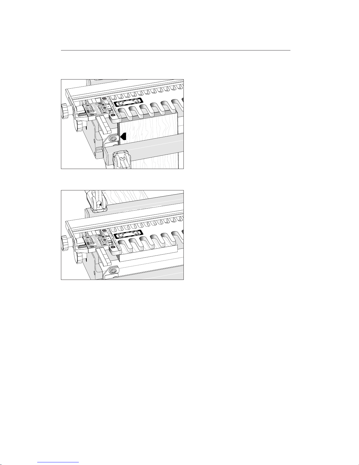
3-4
You will clamp your work pieces against
the front side stop or...
3-5
...the mating rear side stop, depending
on which procedure is to be used.
OPERATION CONCEPTS AND BASIC TEMPLATE FUNCTIONS
Chapter 3
24
Chapter 3 F1 User Guide
Page 31
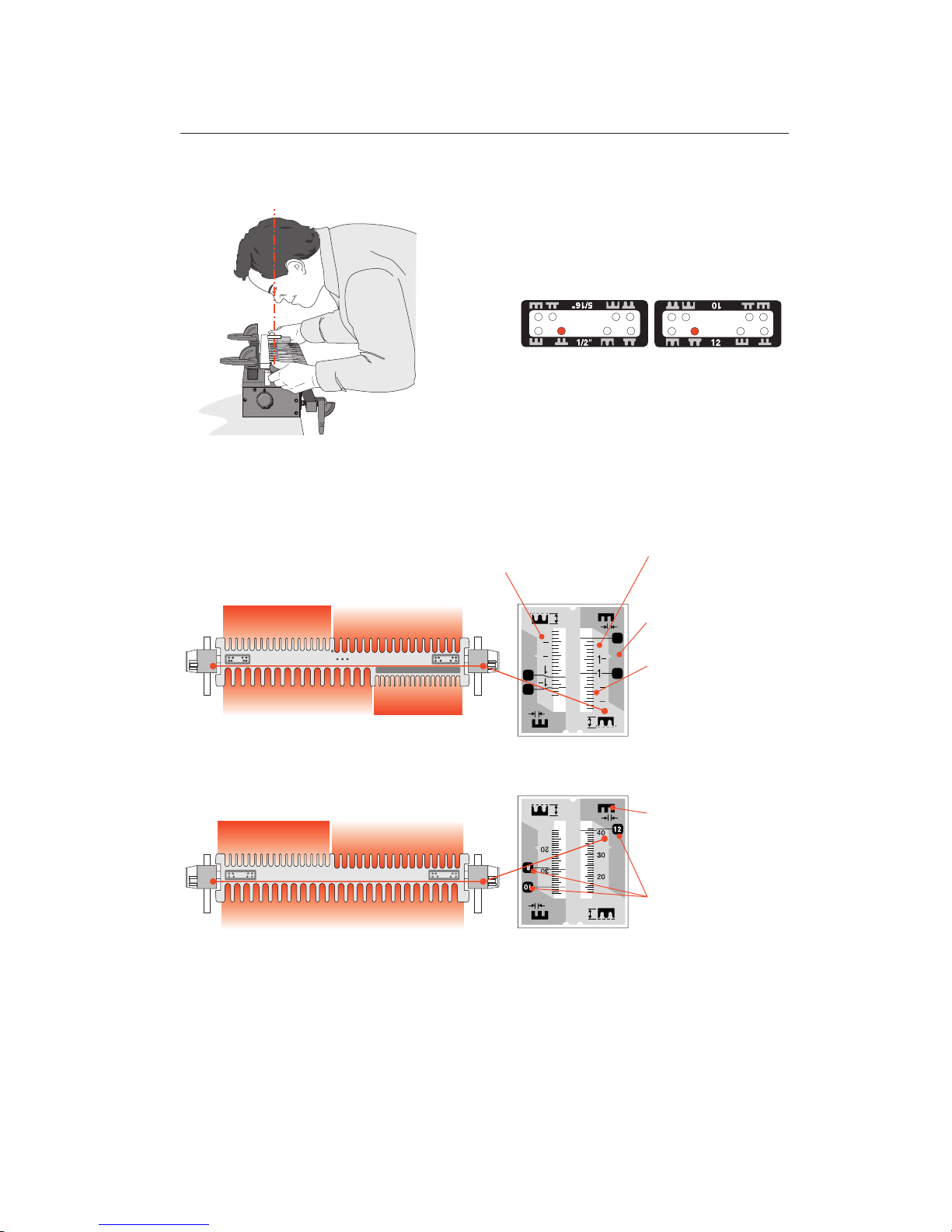
1
/4" Comb
1
/2" Comb
3
/8" Comb
5
/16" Comb
3
4
1
2
1
4
3
4
1
2
1
4
1/4"
1/2"
5/16"
3/8"
12mm Comb
8mm Comb 10mm Comb
25
Template Modes
Template pin hole icons denote the type of
joint and edge finish from each position.
See notes on symmetry and board widths,
chapter 5 page 33.
Throughout the manual, the proper pin
location for each step is highlighted with
red in an inset. Only the active parts of the
inch and millimetre decals will be shown.
Always read scales from directly overhead
to avoid parallax problems.
The active scale is
always on the right side
of each scale assembly.
Green scales are for box
joints.
Grey scales are for
rounded finger joints
and denote the thickness of the vertical pin
board.
The inactive scale is always on the left side
of each scale assembly and is upside down.
Each scale has its own
mode icon representing the current joint
part being made.
There are four settings
for inch box joints, and
three for metric.
The specific settings for each scale are fully described in the appropriate chapters.
Page 32
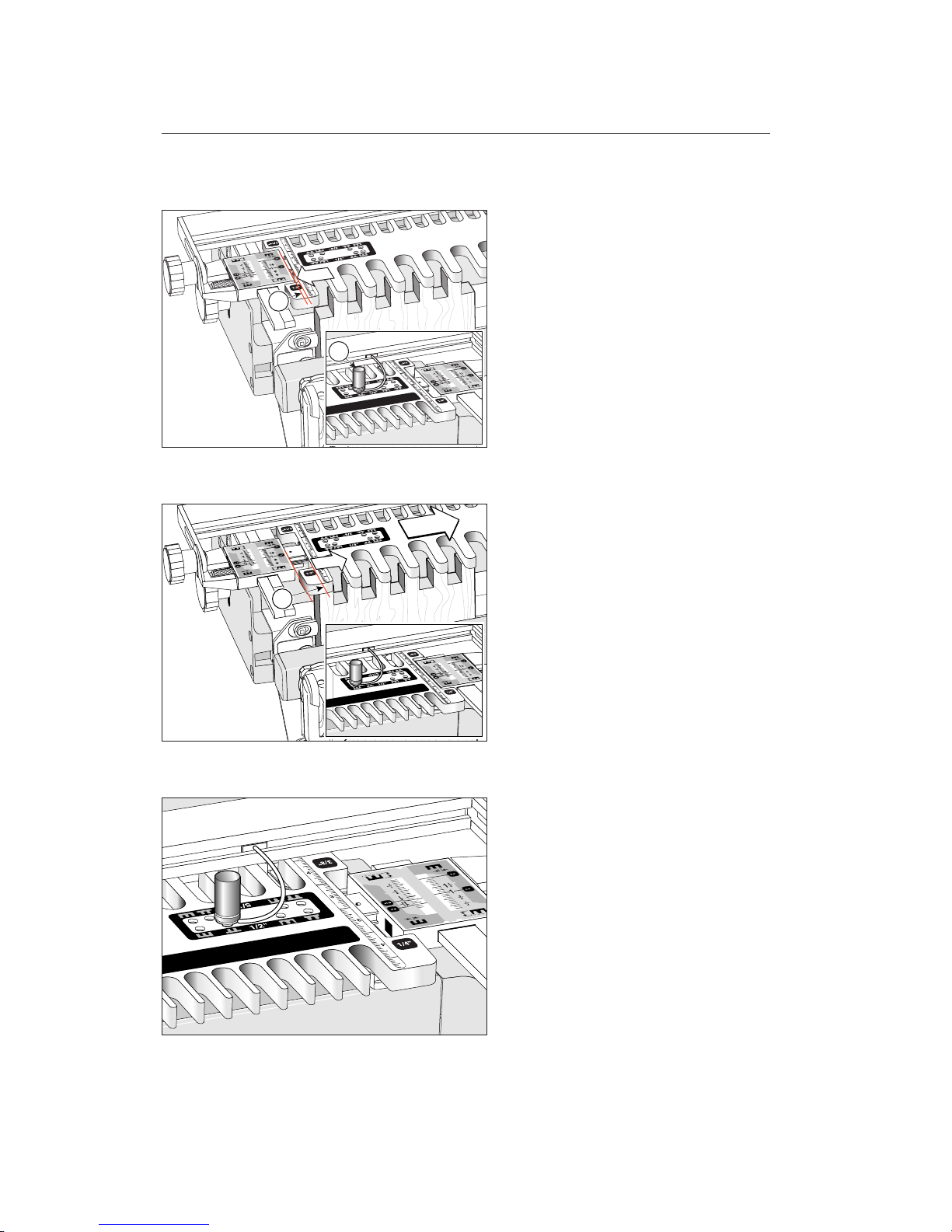
3-6
Mating joints routed under the same comb
have to be offset to achieve correct joint
alignment. On the Leigh F1 template the
offset is achieved by moving the template
left or right by half the pitch of the comb.
This movement is controlled by the template pin, at the other end of the template
➀
.
Note that the template is close to the scale
➁
.
3-7
In this illustration, the template is moved
to the right by half the comb pitch and positioned by the template pin to rout the mating half of the joint in 3-6 above. Note
the increased gap between the scale and template
➁
.
3-8
The template control pin engages the template to the template bar using precisely
positioned holes. The active template pin
holes are always at the opposite end of
the template from the active comb, out
of the way of the router. Most illustrations
will have an inset showing the correct template pin hole position for the procedure.
2
1
2
OPERATION CONCEPTS AND BASIC TEMPLATE FUNCTIONS
Chapter 3
26
Chapter 3 F1 User Guide
Page 33

The Variable Guidebush
System (VGS
)
CHAPTER 4
Page 34

Chapter 4 F1 User Guide
THE VARIABLE GUIDEBUSH SYSTEM (VGS
)
28
Page 35
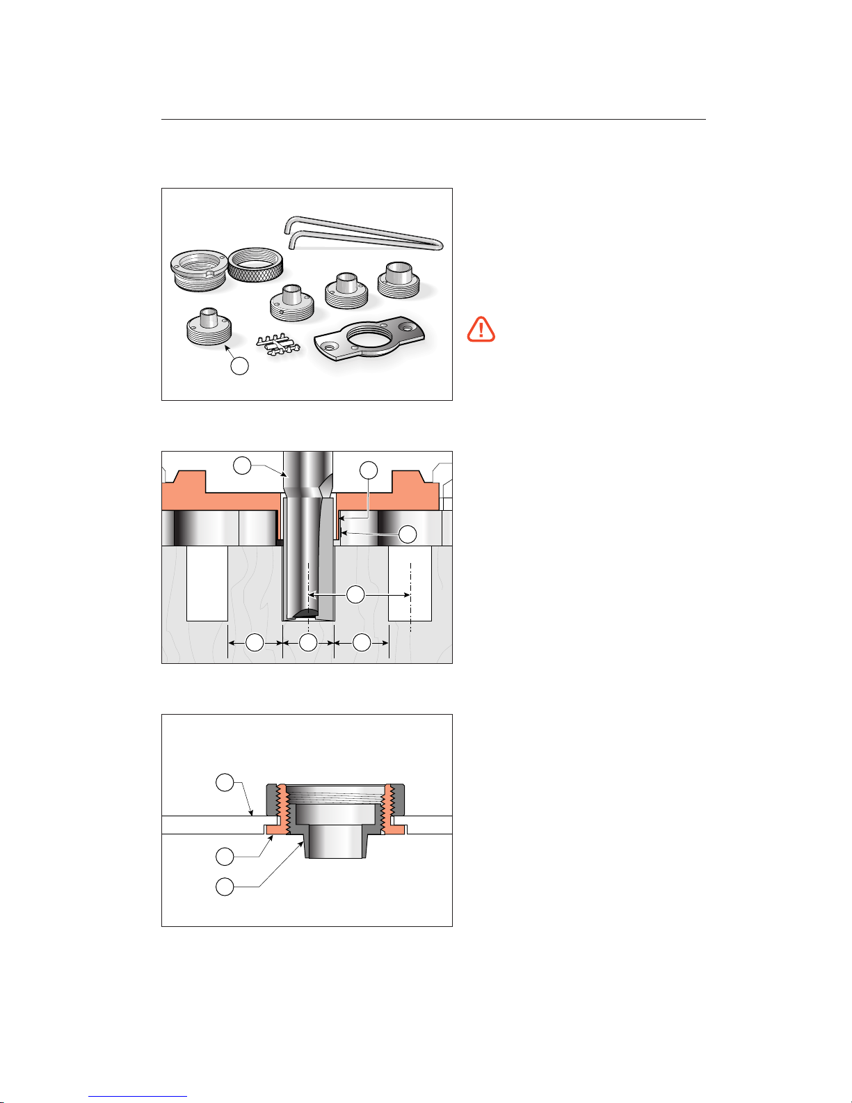
4-1
The F1 Template comes complete with the
Variable Guidebush System (VGS).
Note: One bush
➀
709V is not in the met-
ric set. Each of the tapered bushes is drilled
to accept one of the nylon thread-inserts
(eight of them on a “tree”). See 4-7 to fit.
Do not use the VGS on Leigh Dovetail
Jigs or M2 Mortise Guide Finger accessories; they are only for templates.
Here’s why the VGS is necessary...
4-2
Generally box joints or finger joints are
routed with nominal-size straight cutters
➀
and nominal-size guidebushes ➁against
straight guide surfaces
➂
on nominal pitch
centres
➃
. There are no angles to use for
fit adjustment as there are with dovetails,
so manufacturing tolerances for cutters,
guidebushes, templates and routers give an
“average” fit which is rarely correct.
4-3
However, the Leigh VGS bush has a tapered
barrel
➀
threaded into a holder ➁which
in turn attaches to an adaptor or directly
to the router
➂
.
1
1
2
3
4
? ??
1
2
3
29
Page 36
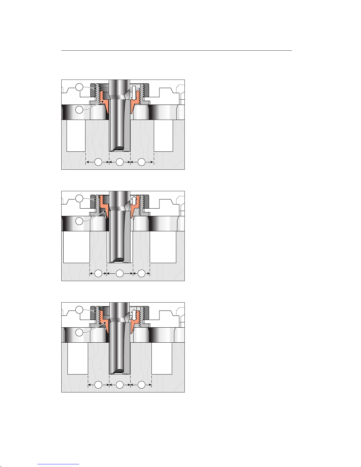
4-4
With the VGS tapered bush ➀screwed
down in the holder (away from the router)
➁
the active bush diameter is increased, allowing no side-to-side movement, and resulting in smaller sockets and larger pins. A
tight fit! Guidebush angle, scale and move-
ment are exaggerated in this sequence of illustrations.
4-5
Raising the bush (screwing the bush into
the holder) allows more side-to-side router/cutter movement, producing larger sockets and
smaller pins, and thus a loose fit.
4-6
A few trial-and-error test cuts and VGS
adjustments will allow you to establish the
right pin and socket sizes for a perfect fit.
Note: One eighth of a turn of the variable
bush changes the joint glue–line interface
by one thousandth of an inch, that is,
0.001" or 0,025mm.
+ +-
2
1
- -+
2
1
= ==
2
1
THE VARIABLE GUIDEBUSH SYSTEM (VGS)
30
Chapter 4 F1 User Guide
Page 37
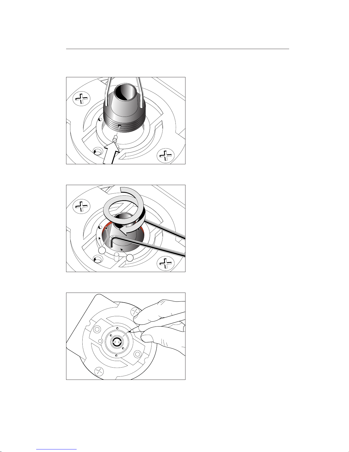
4-7
Fit the holder to the router first. Before fitting a variable bush to a holder, fit one of
the small nylon thread-inserts to the hole
in the side of the thread. Leave the insert
on its “tree” and push into the hole. Then
snap off the “tree”. Once threaded into a
holder, the insert will become trapped and
should not fall out when removed. However,
wrap some scotch tape around the bush to
prevent this. The four inserts and two spares
will last a long time.
4-8
Always start test routing with the bush
flange
➀
turned one to one-and-a-half turns
farther into the router than the holder
flange
➁
.
4-9
When you have the best joint fit, mark the
bush and holder with permanent ink for
future reference. Use the same cutter next
time.
1
2
31
Page 38

THE VARIABLE GUIDEBUSH SYSTEM (VGS)
32
Chapter 4 F1 User Guide
Page 39

Board Width Selection
CHAPTER 5
Page 40

Chapter 5 F1 User Guide
BOARD WIDTH SELECTION
Chapter 5
34
Page 41
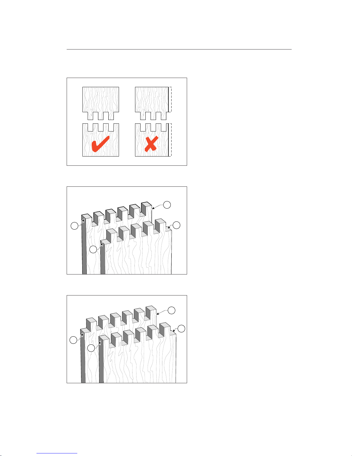
5-1 Board Widths and Joint Symmetry
Unlike the infinitely variable Leigh Dovetail
Jig, a fixed template cannot accommodate
any width of board and still produce a neat
and even finish on both side edges of a joint.
The boards must be cut to specific widths,
depending on the pitch of the comb.
5-2
Symmetrical joints have fingers ➀on both
side edges of one board and sockets
➁
on
both side edges of the mating board.
5-3
Asymmetrical joints have a finger ➀ on
one side edge and a socket
➁ on the other
side edge of each board.
1
1
2
2
2
1
2
1
35
Page 42
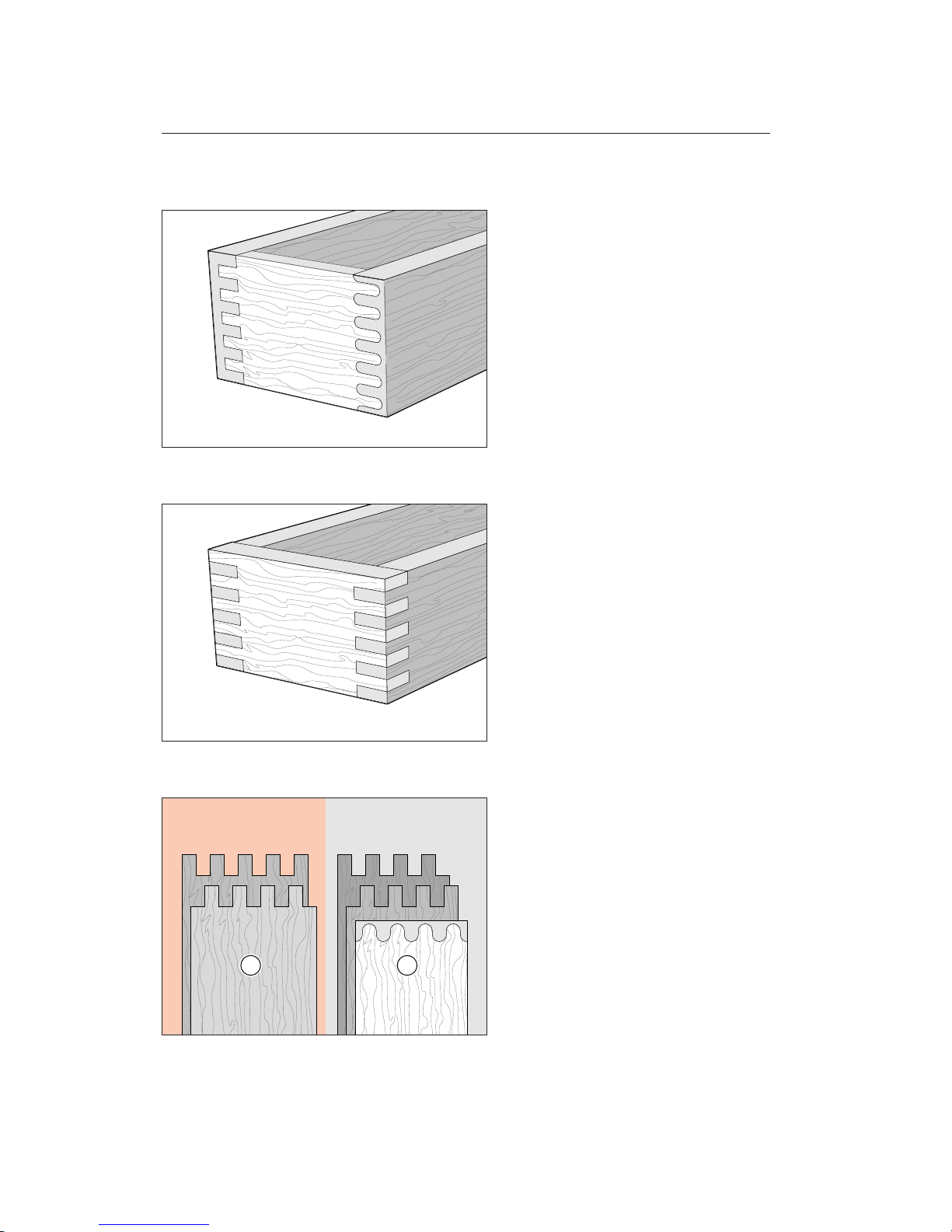
5-4
Symmetrical joints are essential for halfblind corners and rounded finger joints.
5-5
However, ordinary box joints may be asymmetrical and look okay.
5-6
Note: Because the Leigh VGS allows for fit
adjustment on template size, the pitch
widths have been made slightly greater than
the nominal pitch, i.e. slightly more than
two times the cutter diameter. To make
symmetrical square joints
➀
, use the board
widths in red. For asymmetrical square
joints and symmetrical round joints
➁
, use
the board widths in black. Inch board widths
are on page 37. Millimetre board widths
are on page 38. For wider box joints see
chapter 11 page 79.
1 2
BOARD WIDTH SELECTION
Chapter 5
36
Chapter 5 F1 User Guide
Page 43
37
1.970
1
31
/
32
2.986
3
4.002
4
5.018
5
6.034
6
1
/
32
7.050
7
1
/
32
8.066
8
1
/
16
9.082
9
3
/
32
10.098
10
3
/
32
11.114
11
1
/
8
12.130
12
1
/
8
13.146
13
5
/
32
14.162
14
5
/
32
1.470
1
15
/
32
2.236
2
1
/
4
3.002
3
3.768
3
3
/
4
4.534
4
17
/
32
5.300
5
5
/
16
6.066
6
1
/
16
6.832
6
27
/
32
7.598
7
19
/
32
8.364
8
3
/
8
9.130
9
1
/
8
9.896
9
7
/
8
10.662
10
21
/
32
11.428
11
7
/
16
12.194
12
3
/
16
1.220
1
7
/
32
1.861
1
27
/
32
2.502
2
1
/
2
3.143
3
5
/
32
3.784
3
25
/
32
4.425
4
7
/
16
5.066
5
1
/
16
5.707
5
23
/
32
6.348
6
11
/
32
6.989
7
7.630
7
5
/
8
8.271
8
9
/
32
8.912
8
29
/
32
9.553
9
9
/
16
10.194
10
3
/
16
.970
0
31
/
32
1.486
1
1
/
2
2.002
2
2.518
2
17
/
32
3.034
3
1
/
32
3.550
3
9
/
16
4.066
4
1
/
16
4.582
4
19
/
32
5.098
5
3
/
32
5.614
5
5
/
8
6.130
6
1
/
8
6.646
6
21
/
32
7.162
7
5
/
32
7.678
7
11
/
16
8.194
8
3
/
16
1.462
1
15
/
32
2.478
2
15
/
32
3.494
3
1
/
2
4.510
4
1
/
2
5.526
5
17
/
32
6.542
6
17
/
32
7.558
7
9
/
16
8.574
8
9
/
16
9.590
9
19
/
32
10.606
10
19
/
32
11.622
11
5
/
8
12.638
12
5
/
8
13.654
13
21
/
32
14.670
14
21
/
32
1
2
3
4
5
6
7
8
9
10
11
12
13
14
15
16
17
18
19
20
21
22
23
24
25
26
27
28
29
1.087
1
3
/
32
1.853
1
7
/
8
2.619
2
5
/
8
3.385
3
3
/
8
4.151
4
5
/
32
4.917
4
29
/
32
5.683
5
11
/
16
6.449
6
7
/
16
7.215
7
7
/
32
7.981
7
31
/
32
8.747
8
3
/
4
9.513
9
1
/
2
10.279
10
9
/
32
11.045
11
1
/
32
11.811
11
13
/
16
12.577
12
9
/
16
1
2
3
4
5
6
7
8
9
10
11
12
13
14
15
16
17
18
19
20
21
22
23
24
25
26
27
28
29
30
31
32
33
0.900
0
7
/
8
1.541
1
17
/
32
2.182
2
3
/
16
2.823
2
13
/
16
3.464
3
15
/
32
4.105
4
3
/
32
4.746
4
3
/
4
5.387
5
3
/
8
6.028
6
1
/
32
6.669
6
21
/
32
7.310
7
5
/
16
7.951
7
15
/
16
8.592
8
19
/
32
9.233
9
7
/
32
9.874
9
7
/
8
10.515
10
1
/
2
1
2
3
4
5
6
7
8
9
10
11
12
13
14
15
16
17
18
19
20
21
22
23
24
25
26
27
28
29
30
31
32
33
0.712
0
23
/
32
1.228
1
7
/
32
1.744
1
3
/
4
2.260
2
1
/
4
2.776
2
25
/
32
3.292
3
9
/
32
3.808
3
13
/
16
4.324
4
11
/
32
4.840
4
27
/
32
5.356
5
11
/
32
5.872
5
7
/
8
6.388
6
3
/
8
6.904
6
29
/
32
7.420
7
13
/
32
7.936
7
15
/
16
8.452
8
7
/
16
1
2
3
4
5
6
7
8
9
10
11
12
13
14
15
16
17
18
19
20
21
22
23
24
25
26
27
28
29
30
31
32
33
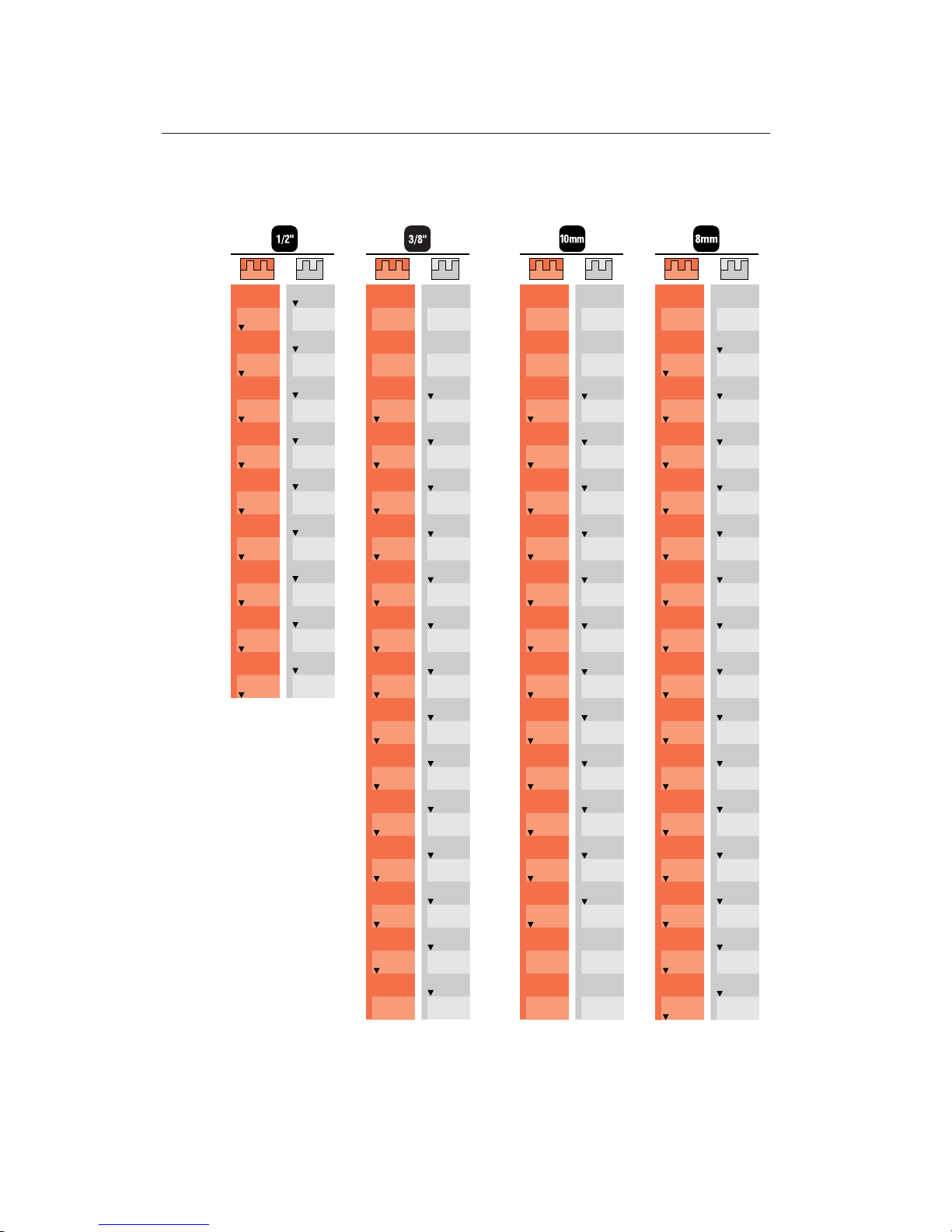
BOARD WIDTH CHART (INCHES)
Note: Decimals show exact board width. Use to the nearest 1⁄32" for width selection.
To make symmetrical square joints, use the board widths in red. For asymmetrical
square joints and symmetrical round joints, use the board widths in black.
Numbers in white column are number of sockets and pins
Page 44
BOARD WIDTH SELECTION
38
Chapter 5 F1 User Guide
BOARD WIDTH SELECTION
Chapter 5
35
59
84
108
133
157
181
206
230
255
279
304
328
352
377
401
426
450
474
499
523
548
572
596
47
72
96
120
145
169
194
218
242
267
291
316
340
365
389
413
438
462
487
511
535
560
584
1
2
3
4
5
6
7
8
9
10
11
12
13
14
15
16
17
18
19
20
21
22
23
24
25
26
27
28
29
30
31
32
33
34
35
36
37
38
39
40
41
42
43
44
45
46
47
48
49
1
2
3
4
5
6
7
8
9
10
11
12
13
14
15
16
17
18
19
20
21
22
23
24
25
26
27
28
29
30
31
32
33
34
35
36
37
38
39
40
41
42
43
44
45
46
47
48
49
1
2
3
4
5
6
7
8
9
10
11
12
13
14
15
16
17
18
19
20
21
22
23
24
25
26
27
28
29
30
31
32
33
34
35
36
37
38
39
40
41
42
43
44
45
46
47
48
49
29
49
70
90
111
131
151
172
192
213
233
254
274
294
315
335
23
39
56
72
89
105
121
138
154
171
187
204
220
236
253
31
48
64
80
97
113
130
146
162
179
195
212
228
245
39
60
80
100
121
141
162
182
202
223
243
264
284
305
325
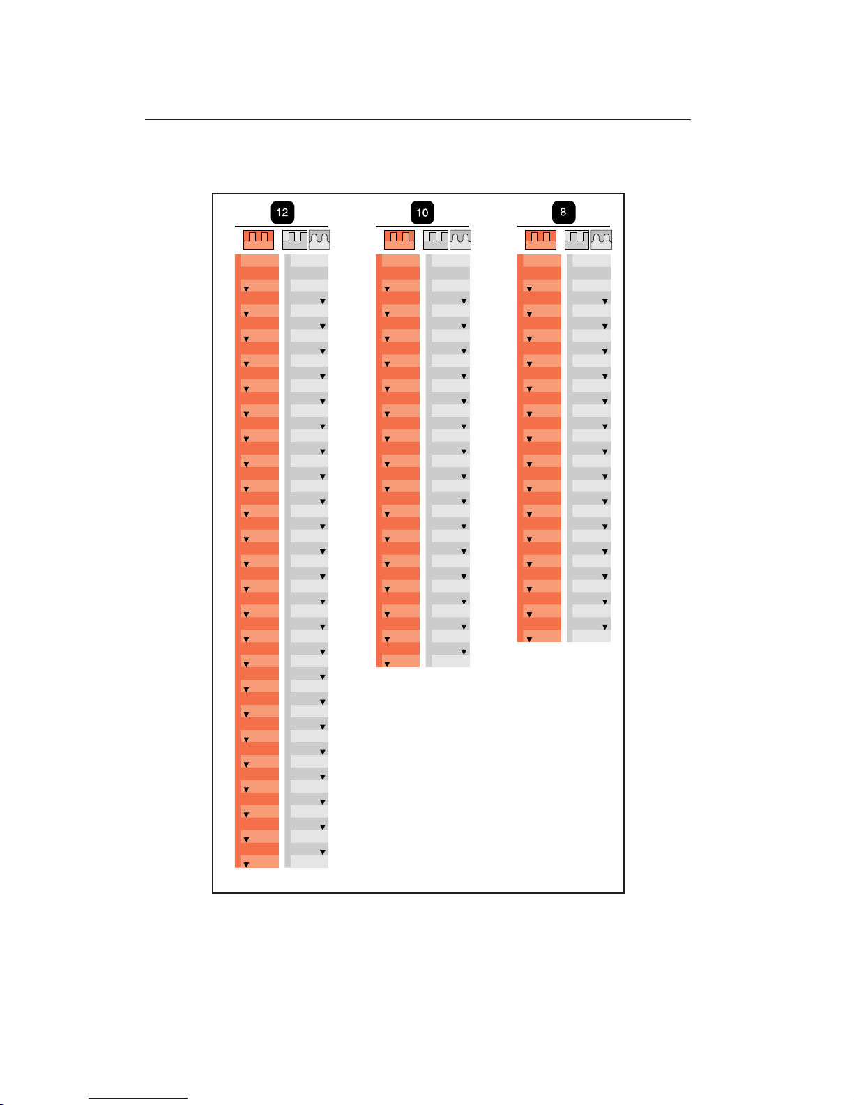
BOARD WIDTH CHART (MILLIMETRES)
Note: Use to the nearest millimetre for width selection. To make
symmetrical square joints, use the board widths in red. For asymmetrical square joints and symmetrical round joints, use the board
widths in black.
Numbers in white column are number of sockets and pins
Page 45

Box Joint Procedures
CHAPTER 6
Page 46

BOX JOINT PROCEDURES
Chapter 6 F1 User Guide
40
Page 47
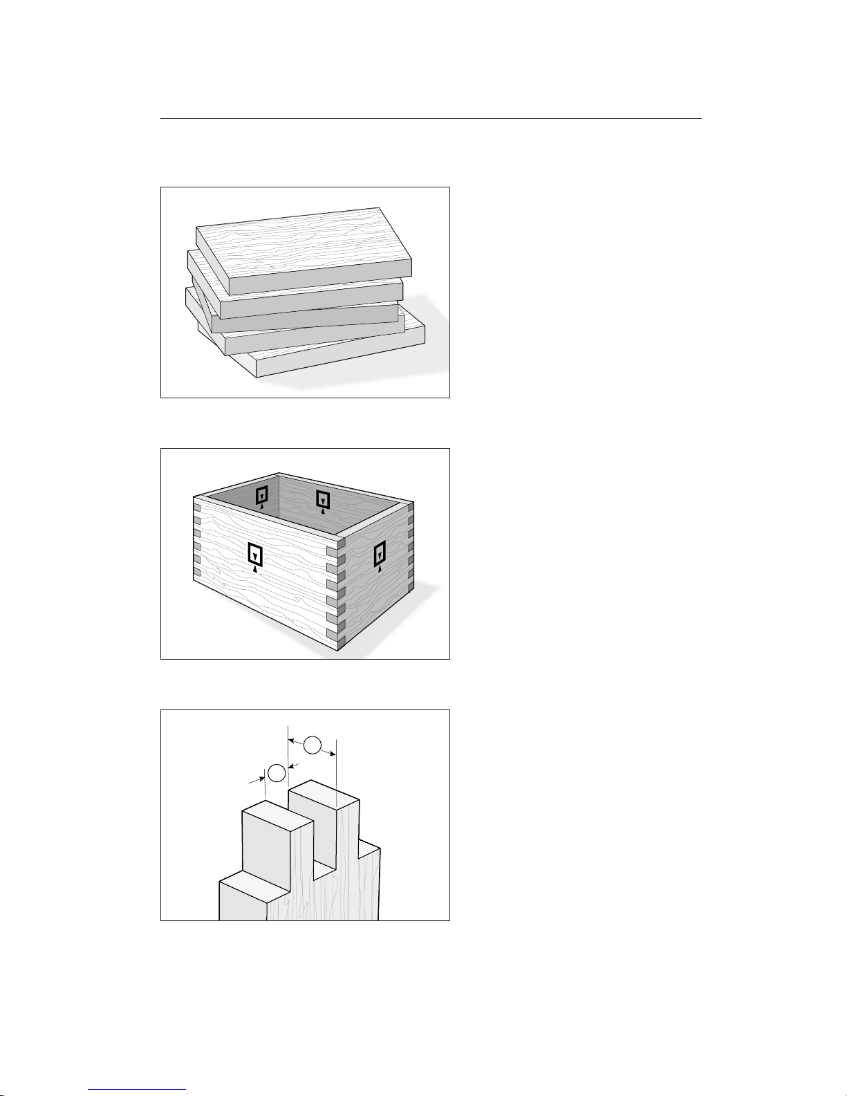
6-1
Always use scrap boards to test for fit. Width
and thickness of the scrap boards is not critical.
6-2
Let’s rout some simple box joints. These
general instructions are the same for any of
the four comb sizes. The illustrations show
the left-hand side of the jig; you could be
working on the right-hand side. Rout only
single corners to adjust the joint fit.
Note: This chapter combines instruction for
joint procedures and joint fit. Follow this
through step by step the first time, but there
is also a “quick fit test” method in Chapter
12, Figs. 12-7 to 12-9.
6-3 Cutter and Guidebush Selection
There are no hard and fast rules for sizing
of pins and sockets for box joints; but typically the sockets
➀
are one half to one quar-
ter of the board thickness
➁
. Generally,
the smaller the cutter, the greater the strength
because of the greater gluing area.
1
2
41
Page 48
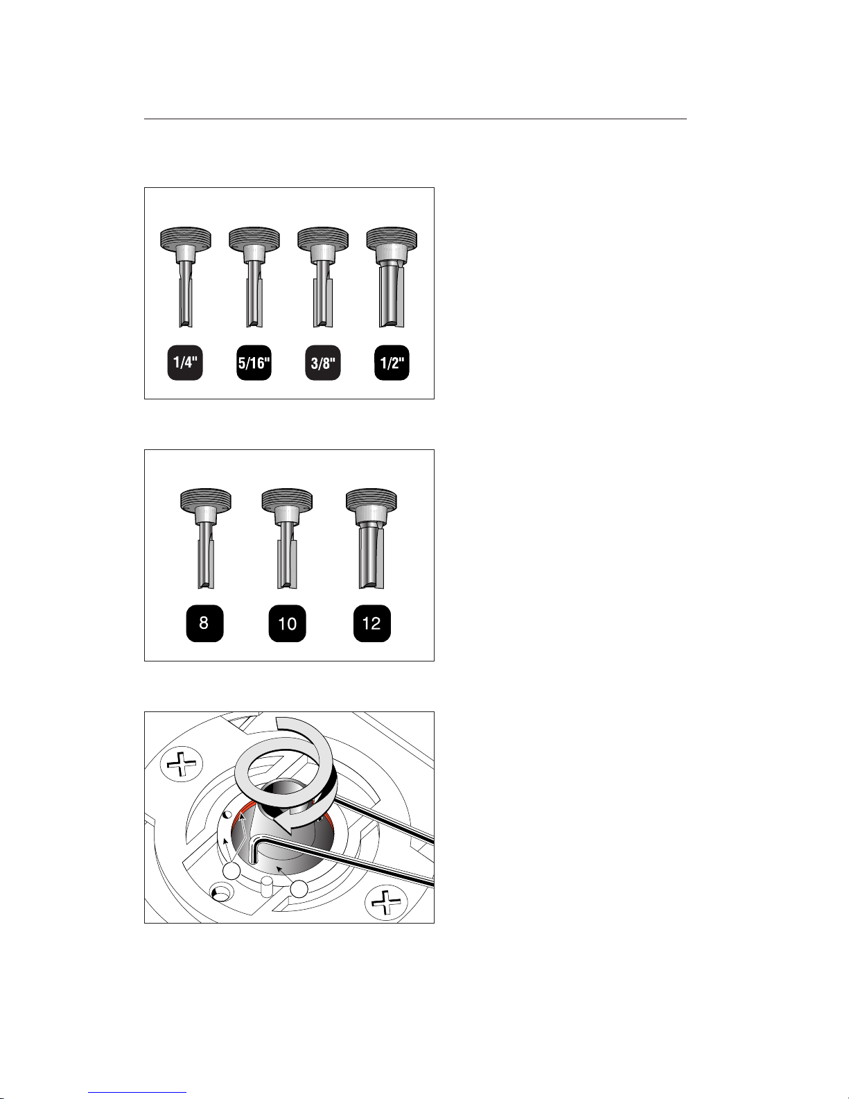
6-4
Select the correct variable bush and cutter combination for the comb size to be
used. The cutter size is the same as the designated comb size. For smaller size box joints
see chapter 10 page 67.
The inch template can use four sizes of cutter and comes with four guidebushes.
6-5
The millimetre template can use three sizes
of cutter and comes with three guidebushes.
6-6
Always start test routing with the bush
flange
➀
turned one to one-and-a-half turns
farther in than the holder flange
➁
.
709V 711V 713V 716V
711V 713V 716V
1
2
BOX JOINT PROCEDURES
Chapter 6 F1 User Guide
42
Page 49
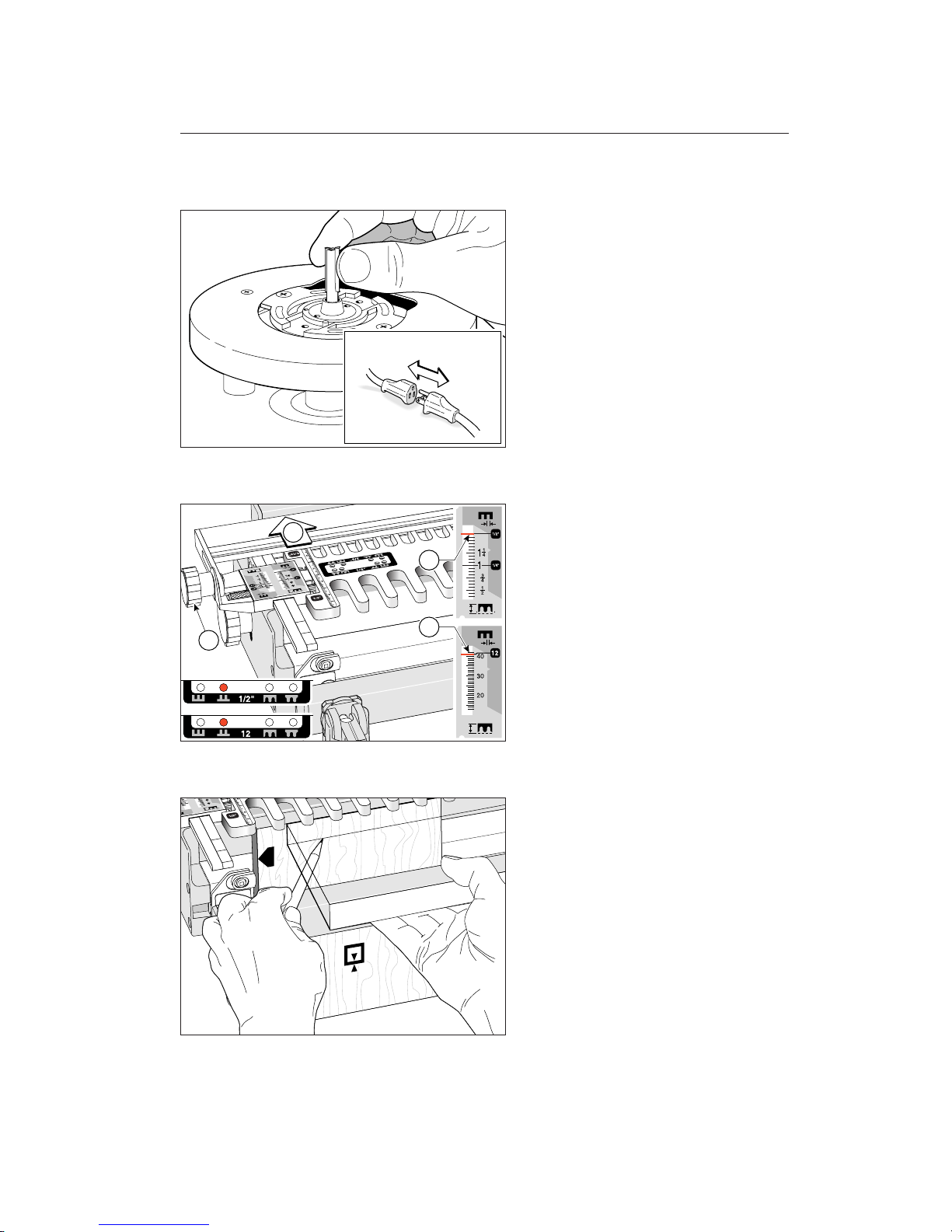
6-7
Fit the selected cutter (that matches the
bush) to the router and tighten securely.
6-8
Set the scale on the comb size to be used
(example here;
1
⁄
2"[12mm] comb
➀
). Loosen
fence knobs
➁
and move fence ➂ to rear
and re-tighten knobs
➁
. Note: The fence
is only used for rounded finger joints. If
the fence is in the way of a large router
base, simply lift and lock the fence so
the router base can slide under it. Position
the template with the template pin in the
B
position. Remember, the template pin
is always positioned at the opposite end of the
template.
6-9
Clamp the workpiece against the side stop,
with the end edge flush under the template.
The board may be clamped face side in or
out
j
. Mark and adjust the depth of cut
to suit the thickness of the boards. Use the
board to be joined to mark the depth of
cut.
2
3
1
1
43
Page 50
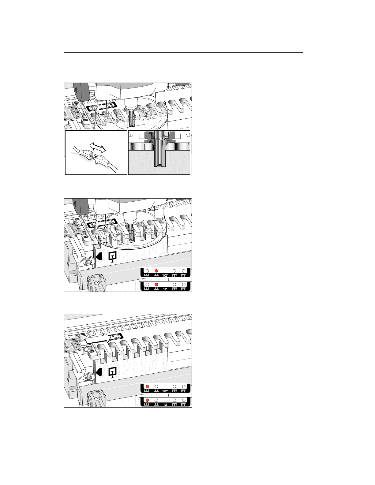
6-10
Adjust the cutter to cut down to the centre of the pencil line. Make sure the collet
will not rub on the guidebush.
6-11
Rout one end of a scrap board. Make sure
to touch the guidebush on both sides of
each template opening.
6-12
Remove the template pin and move the
template to the
A
position, then refit the
pin. Rout the mating board.
BOX JOINT PROCEDURES
Chapter 6 F1 User Guide
44
Page 51
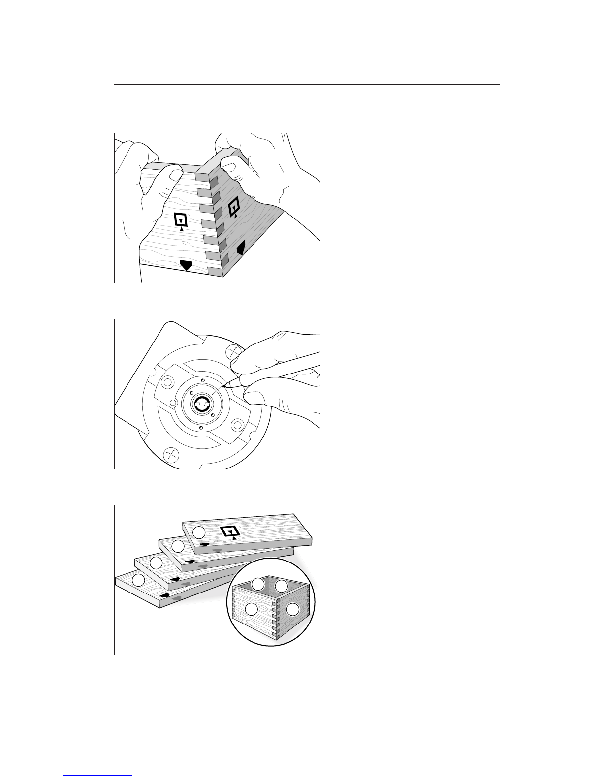
6-13
Test the two boards for fit. Adjust the height
of the variable guidebush by trial and error
and rout more pairs of test boards to achieve
the desired fit. Remember, lower the variable bush for a tighter joint and raise the
variable bush for a looser joint.
6-14
When the fit is just right, mark the bush
and holder with permanent ink for future
reference.
6-15
Let’s make a box.
Prepare four boards and mark them 1, 2,
3, and 4 . Then select the grain alignment
and mark the common top (or bottom)
edge. Don’t worry about face side selection,
this can be done after routing.
2
2
1
1
3
3
4
4
45
Page 52
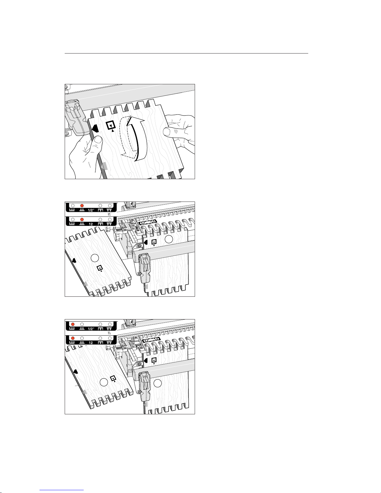
6-16
All square box joint boards (for boxes or
end-on-end joints) are clamped alternately face in and face out
j
, always with
the same side edge against the side stop.
6-17
Rout both ends of boards 1 and 3 in position
B
. Be sure to keep the same edges to
the side stop.
6-18
Rout both ends of boards 2 and 4 in position
A
. Keep the same edges to the side
stop.
1
3
2
4
BOX JOINT PROCEDURES
Chapter 6 F1 User Guide
46
Page 53
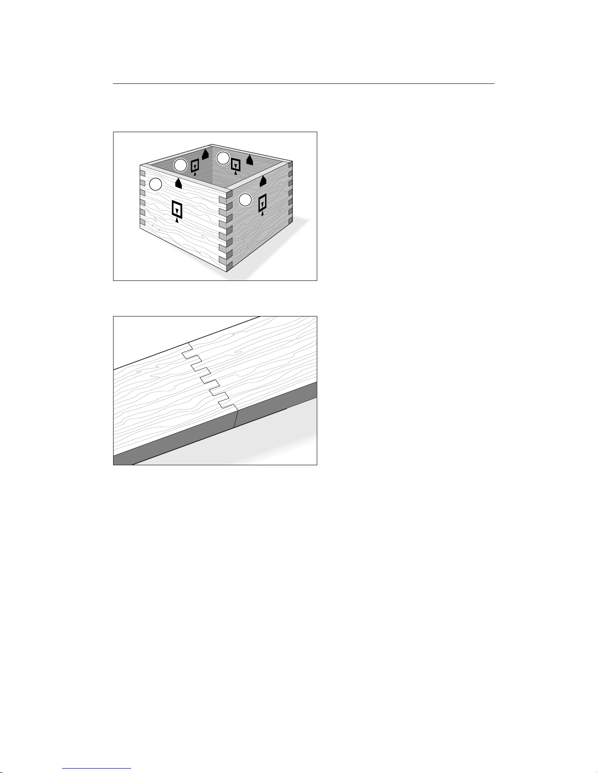
6-19
Keeping the marked side stop edges of all
boards toward the top (or bottom) of the
box, select the preferred outside faces of the
boards and assemble the box. Remember;
box joint corners need clamping from both
directions, or use strap clamps and blocks.
6–20
The same method will produce square endon-end joints.
2
1
3
4
47
Page 54

BOX JOINT PROCEDURES
Chapter 6 F1 User Guide
48
Page 55

Rounded Half-Blind
Finger Joint Procedures
CHAPTER 7
Page 56

ROUNDED HALF-BLIND FINGER JOINT PROCEDURES
Chapter 7 F1 User Guide
50
Page 57
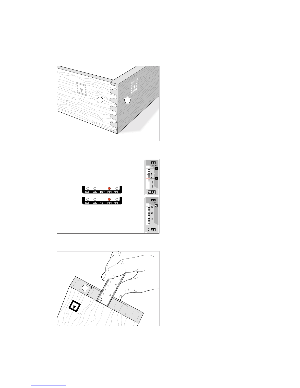
7-1
Rounded half-blind finger joints make
an attractive drawer front
➀
to side ➁con-
nection. See page 97, appendix II for cutter
selection.
7-2 Routing Half-Blind Joints
Set the template scale to the thickness of
the pin board on the grey scale, e.g. 1"[25mm]
shown here. Set the template pin in the
E
hole.
7-3
Measure the required depth of horizontal
cut into the pin board
➀
, usually 1⁄8"[3mm]
less than the board thickness.
12
1
51
Page 58
7-4
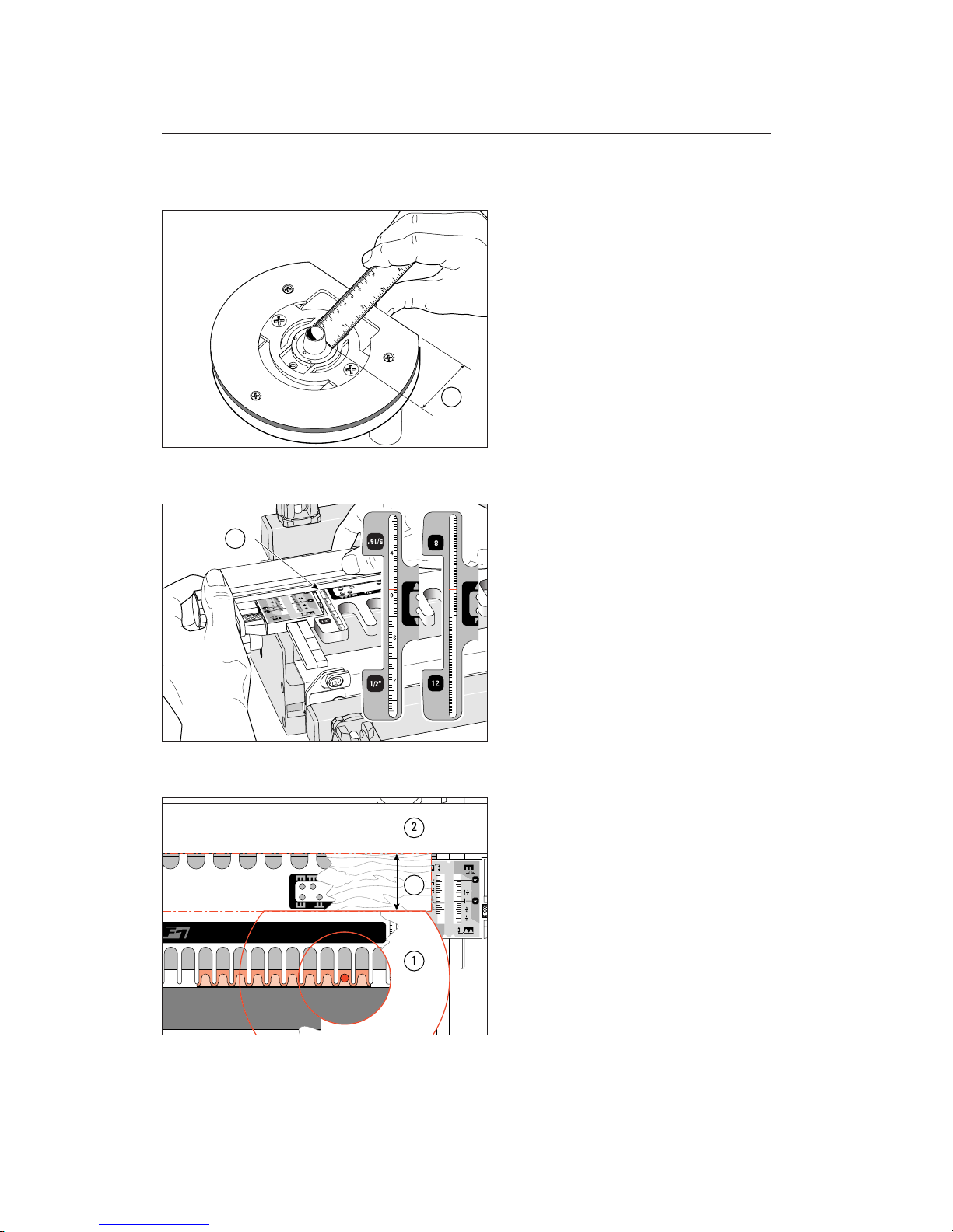
Measure the distance from the guidebush
to the rear edge of the router base
➁
.
7-5
Add dimensions ➀and ➁. Set the router
stop fence to this total on the fence scale
➂
at both ends of the template. Tighten
the fence knobs. If your router base is small,
see 7-6 below.
7-6
Some router bases ➀are quite small and it
may not be possible to get the router fence
➁
far enough forward to be effective. Use a
parallel-sided block
➂
between the router
and fence. Offset the fence setting by the
width of the block.
2
12
11
10
9
8
7
12
11
10
9
8
7
3
1
2
3
ROUNDED HALF-BLIND FINGER JOINT PROCEDURES
Chapter 7 F1 User Guide
52
Page 59
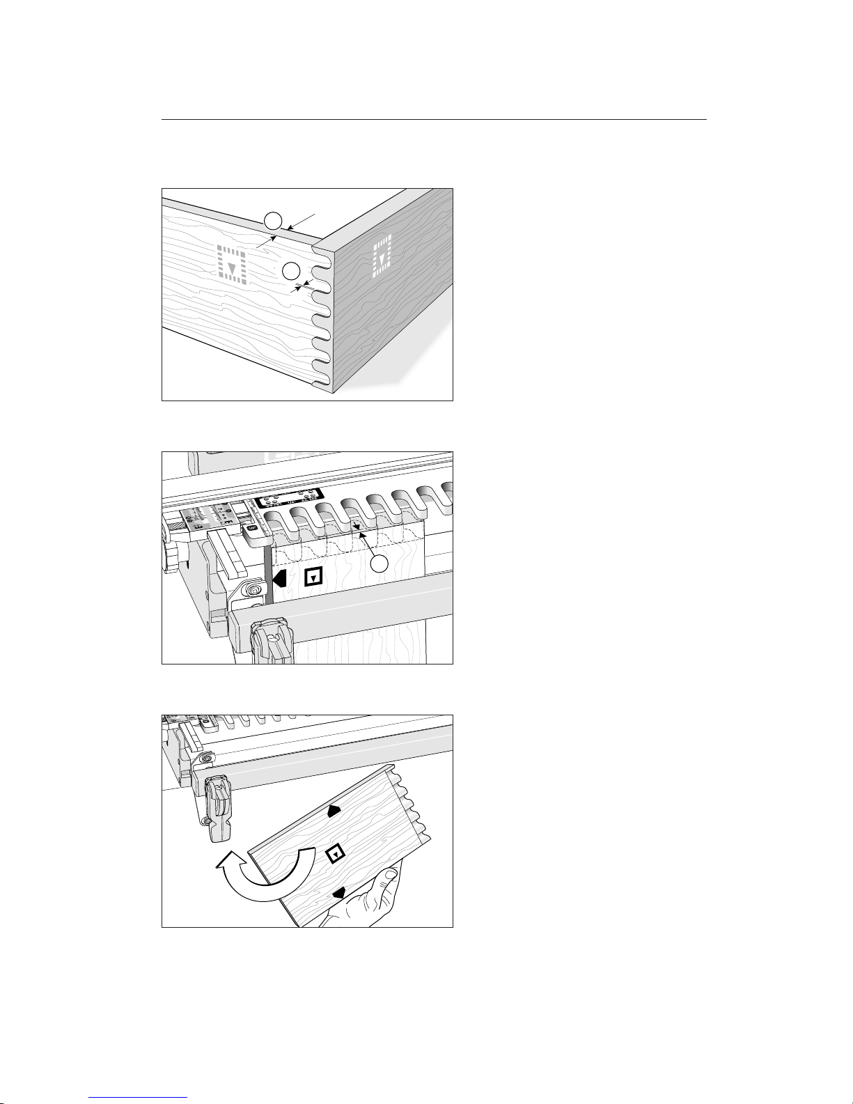
7-7
Set the depth of cut to slightly greater than
the thickness of the side board
➀
. You
want the drawer front fingers to come
through the side sockets by no more than
1
⁄64
"[0,25mm]
➁
for cleanup later, just
like half-blind dovetails.
7-8
Clamp the pin board vertically against the
side stop with the end edge flush under the
template. The inside face
i
of the finished
boards face away from the jig body. With
the scale set on the pin board thickness, the
board should project
1
⁄8"[3mm] in front of
the guide tips
➀
.
7-9
The inside face iof all boards used for
making rounded half-blind joints always
face away from the jig body just like halfblind dovetail boards on the dovetail jig.
So alternate side edges go against the side
stop and boards must all be exactly the same
width.
2
1
1
53
Page 60
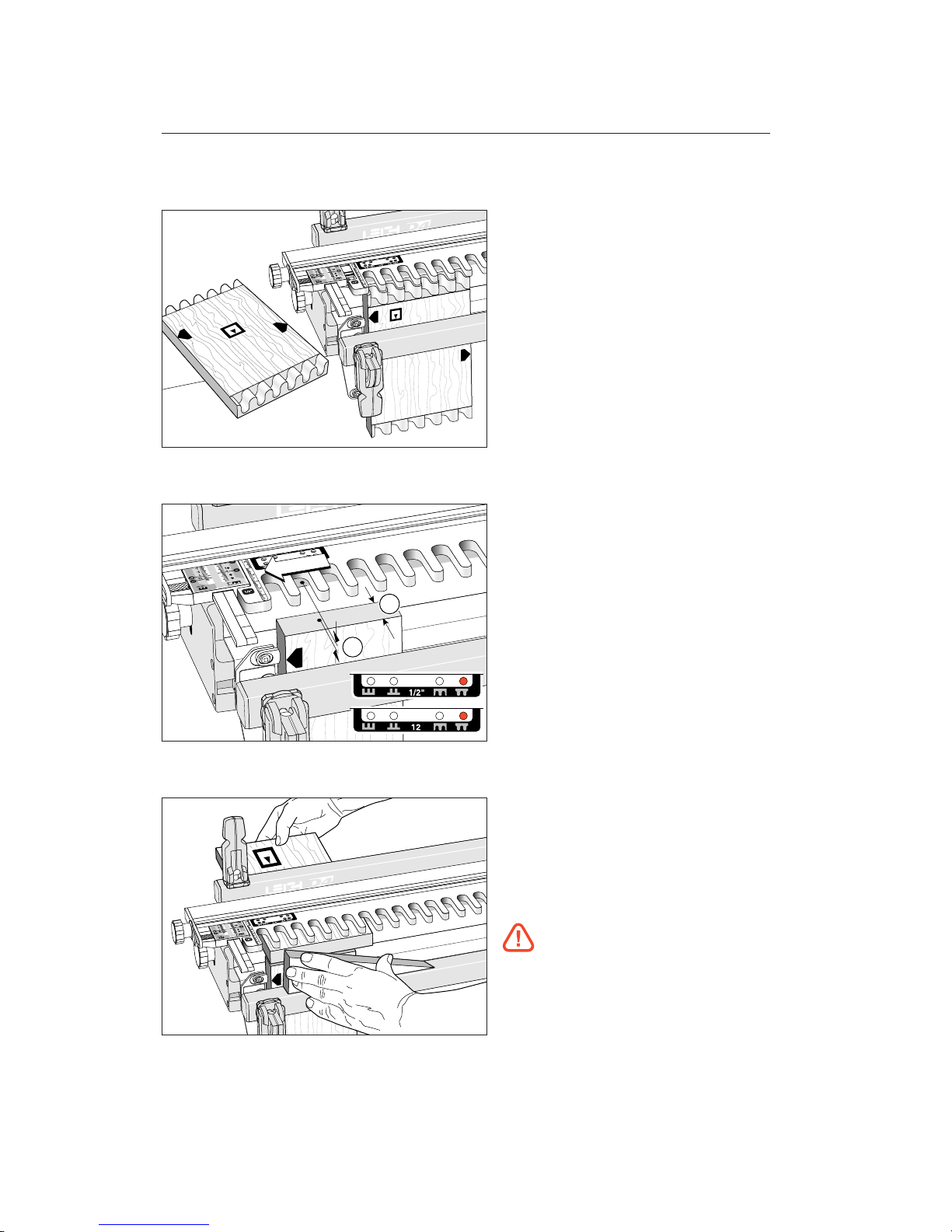
7-10
Rout the rounded pins. Do not push against
the router fence. The router should just
touch the fence. Rout both ends of both
pin boards at this setting. Do not change
the fence setting.
7-11
Insert the template pin in the Fhole. Do
not change any other setting. Clamp a scrap
board
➀
of exactly the same thickness as
the pin board in the front clamp, with
the top end edge slightly below the top surface of the jig body
➁
.
7-12
Clamp one of the box side boards horizontally in the rear clamp, with the inside
face
i
of the board facing away from the
jig body and the end edge flush with the
outer edge of the vertical scrap board.
Tear-out Warning! Do not rout this
board before reading the following:
2
1
ROUNDED HALF-BLIND FINGER JOINT PROCEDURES
Chapter 7 F1 User Guide
54
Page 61
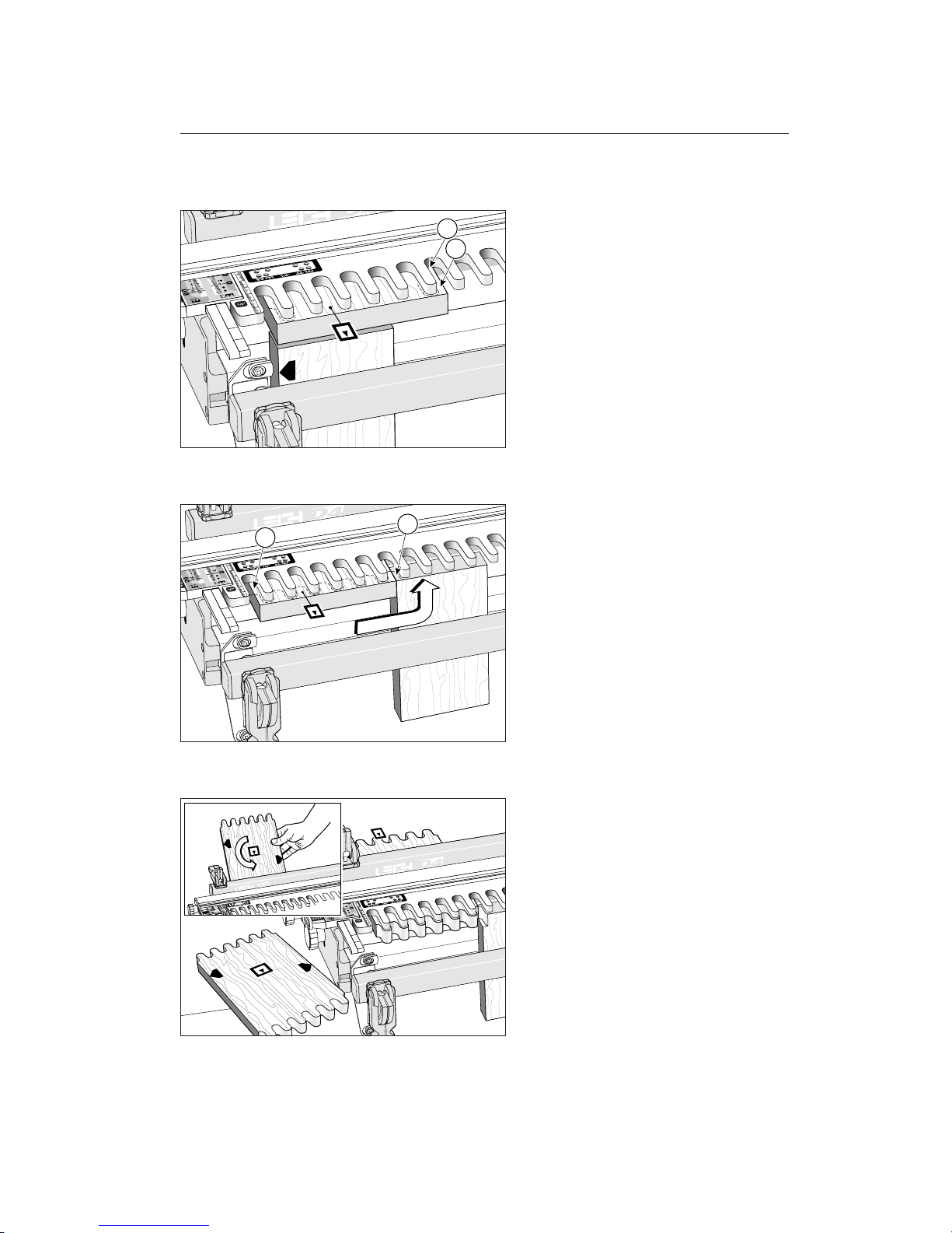
7-13
If you rout this horizontal board in the conventional way you may tear away the right
hand board edge
➀
, although some woods
will rout quite cleanly. If a plunge router is
used, gently plunge down at the rear of the
socket
➁
and rout out toward you.
7-14
When using combs at the left end of the
jig, the best way to avoid the right-edge
tearout problem is to clamp the front scrap
➀
against the right side edge of the board.
Simply clamp it under the front clamp bar,
making sure it’s firmly against the edge of
the board. By rotating and flipping its position, one scrap will be good for 4 cuts. The
edge at
➁
may cause the router to pull itself
quickly into the template comb, so good
router control is important.
7-15
Rout both ends of both side boards, with
inside faces
i
away from the jig body.
1
2
1
2
55
Page 62
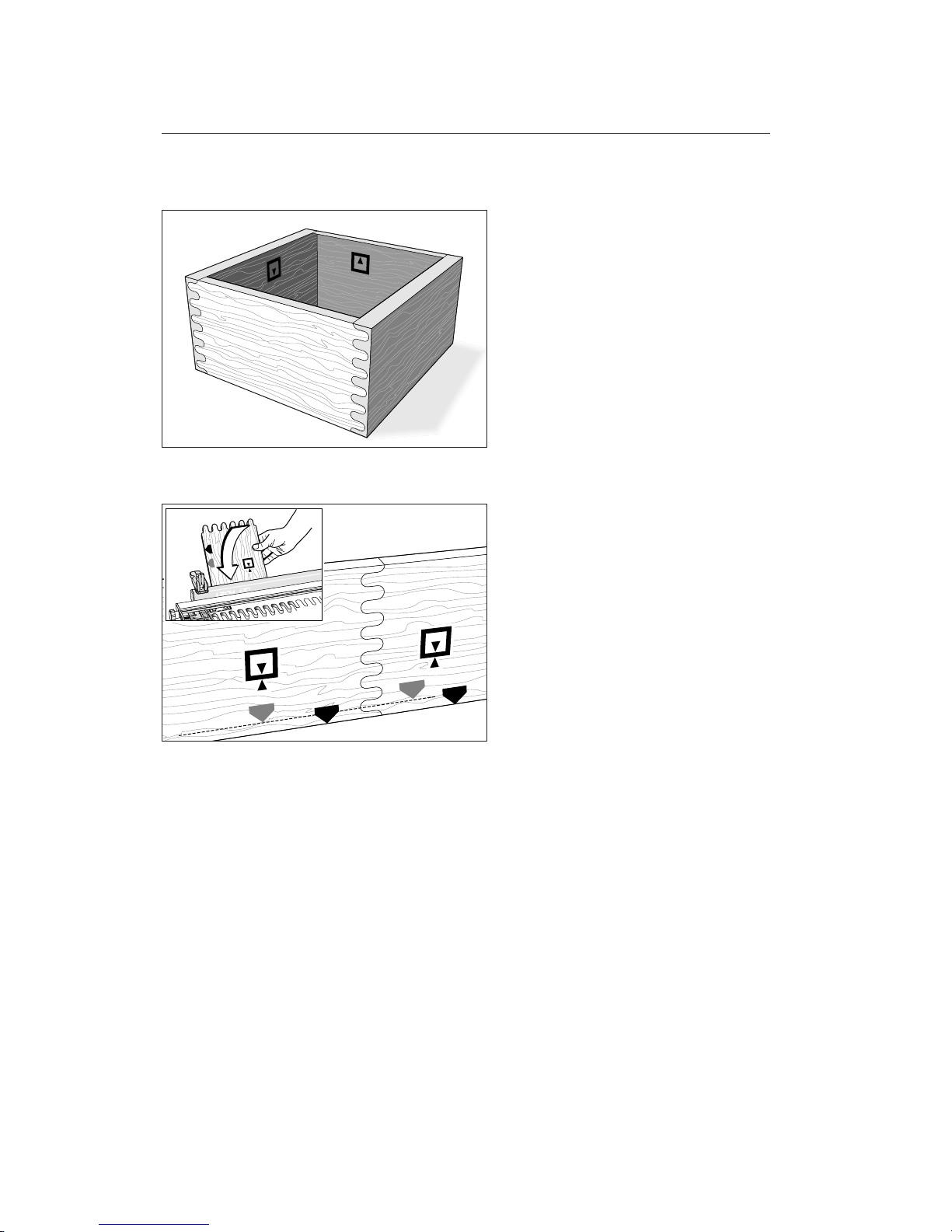
7-16
Assemble in the usual way. You will probably need to clamp in both directions when
gluing up.
7-17 Rounded End-on-End Joints
These are routed exactly the same way as
the box–side boards in the previous instruction, except that you must keep the same
side edges against the side stop and alternate face side up/face side down
j
. Rout
half the boards at the
E
setting and the
other half at the
F
setting.
ROUNDED HALF-BLIND FINGER JOINT PROCEDURES
Chapter 7 F1 User Guide
56
Page 63

Square Half-Blind
Box Joint Procedures
CHAPTER 8
Page 64

SQUARE HALF-BLIND BOX JOINT PROCEDURES
Chapter 8 F1 User Guide
58
Page 65
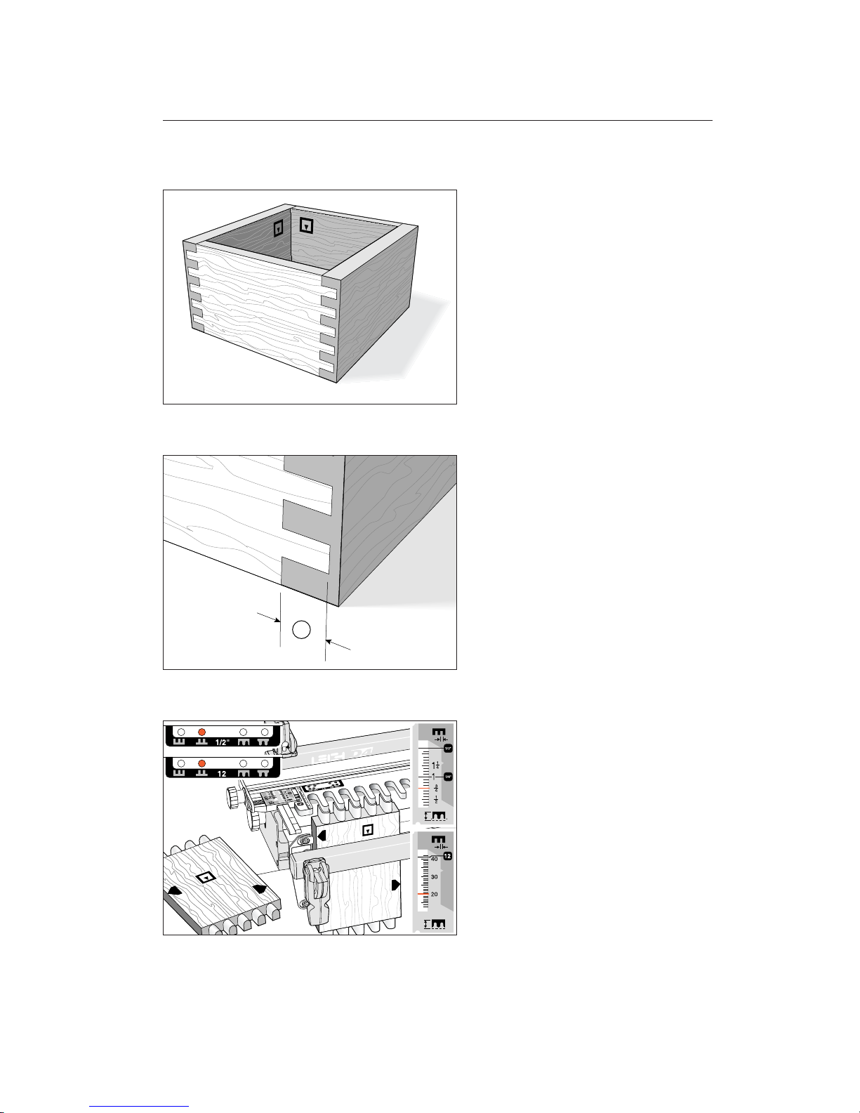
8-1 Square Half-Blind Joints
Just like the rounded half-blind joints: boards
must be exactly the same width, inside
faces
i
always face away from the jig body,
and alternate edges are placed against the
side stop. Even though part of this joint is
rounded, we use the square pitch pin settings to rout it. Because part of this joint
is rounded, only the nominal size cutters
may be used:
1
⁄4", 5⁄16", 3⁄8", and 1⁄2" for inch
joints; or 8,10, and 12mm for metric joints.
See page 97, appendix II for cutter selection.
8-2
Set the depth of cut ➀to about 1⁄
8"[3mm]
less than the drawer-front thickness.
8-3
Set the template pin on the Bsetting and
the grey scales to the thickness of the box
sides, e.g. 3/4" [20mm] shown here. Move
the router fence to the rear, it is not used
in this procedure. Rout the box side ends
vertically in the front clamp.
1
59
Page 66
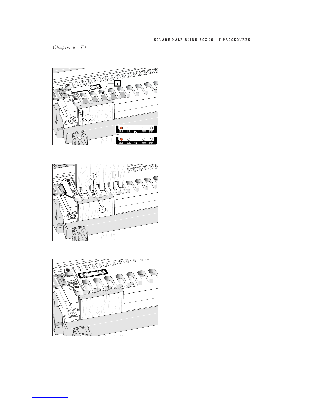
8-4
Set the template pin on A. Clamp a scrap
piece vertically in the jig front with its
top end slightly above the jig body
➀
.
Clamp a box front horizontally with the
inside face
i
away from the jig body, and
the front end edge against the scrap board.
8-5
Place one of the routed box sides vertically through the template with the rounded part of the fingers in the rounded guide
crotches. Adjust the template so the front
face of the side board
➀
is 1⁄
16"[1,5mm] in
from the end edge of the box front
➁
. Lock
the scales on the same setting at both ends.
8-6
Rout a test piece to test the grey scale setting and adjust the template in or out to
produce the required flush fit.
1
;;;;
1
2
;;;;
SQUARE HALF-BLIND BOX JOINT PROCEDURES
Chapter 8 F1 User Guide
60
Page 67
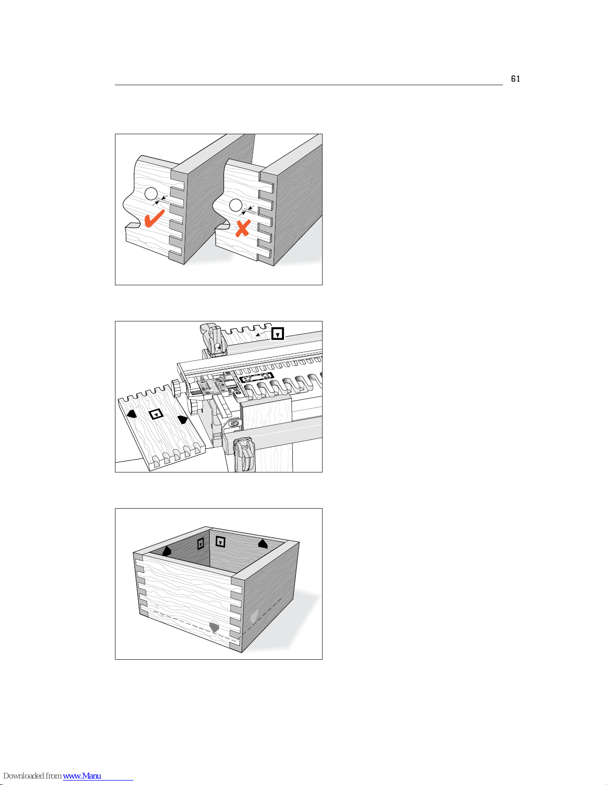
8-7
The drawer front pins should project through
the side sockets by no more than
1
⁄64
"[0,25mm] for clean-up
➀
. If the sides
project
➁
, adjust the template inward to
suit.
8-8
When satisfied with the fit, rout all the ends
of the box fronts and backs in this mode.
8-9
Assemble and glue in the usual way.
1
2
;;;;
61
Page 68
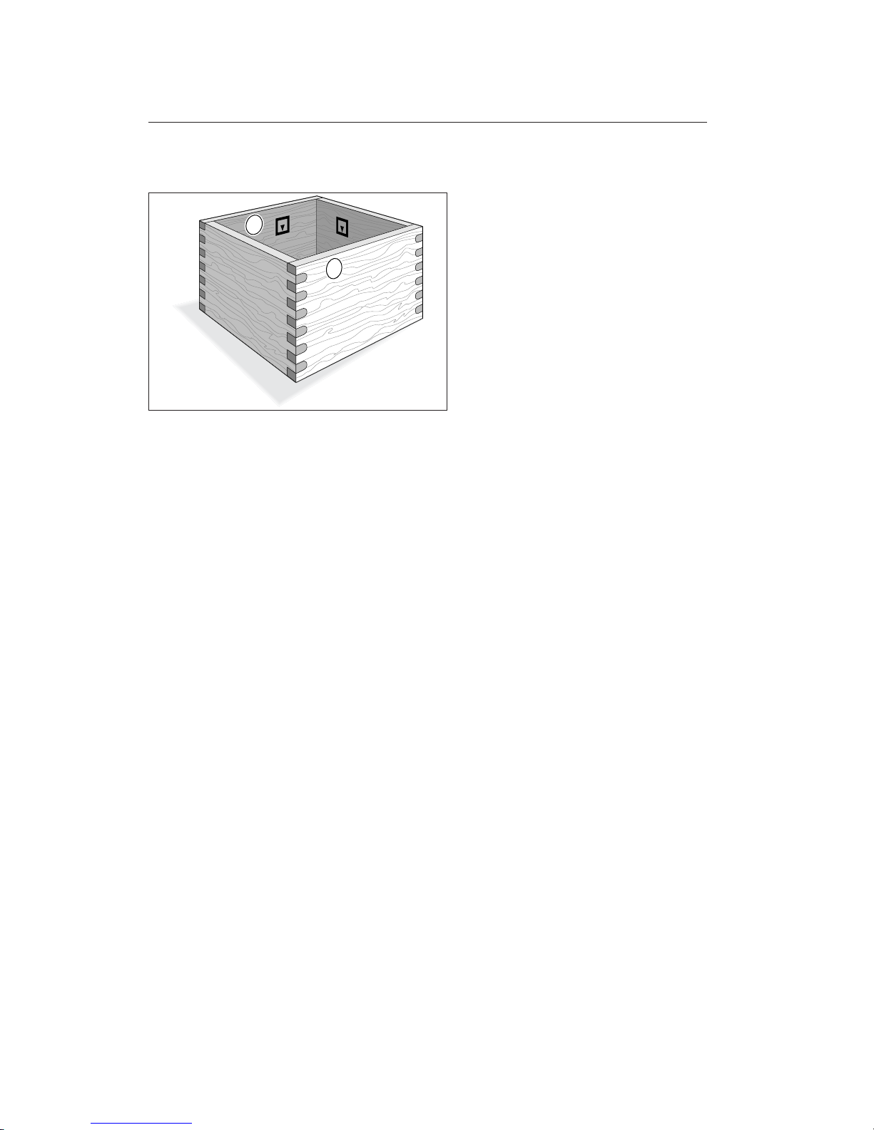
8-10 Rounded Square Box Joints
These are routed the same way as square
half-blind box joints, but the depth of
cut is slightly greater than the thickness of
the front and rear boards
➀
.
1
1
SQUARE HALF-BLIND BOX JOINT PROCEDURES
Chapter 8 F1 User Guide
62
Page 69

Rabbetted Half-Blind
Finger Joints
CHAPTER 9
Page 70

RABBETTED HALF-BLIND FINGER JOINTS
Chapter 9 F1 User Guide
64
Page 71
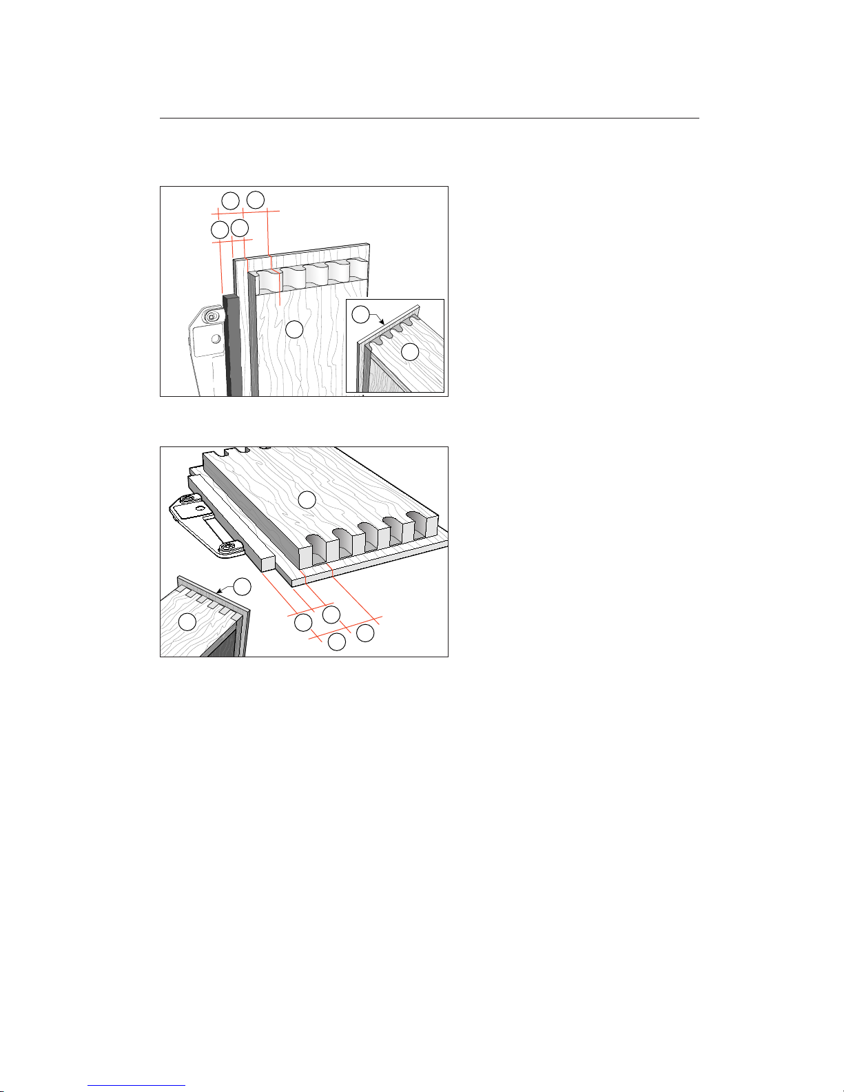
9-1 Rabetted Half-Blind Finger Joints
Rabbetted drawer fronts ➀and the mating sides
➁
have to be blocked away from
the side stops. Block drawer sides
➁
away
from the side stops by one complete comb
pitch (A). Block the drawer front
➀
away
by (B) which is comb pitch (A) minus rabbet width (C).
9-2
The same rule applies to rabbetted square
box joints.
A
A
B
C
1
1
2
A
A
B
C
1
1
2
65
Page 72

RABBETTED HALF-BLIND FINGER JOINTS
Chapter 9 F1 User Guide
66
Page 73

Small Box Joints
CHAPTER 10
Page 74

Chapter Foreword
These instructions are based on the assumption that you have mastered the routing of
the basic box joint, and are thoroughly
familiar with those procedures. Also that
you have read the Hints and Tips Chapter
12.
SMALL BOX JOINTS
Chapter 10
68
Chapter 10 F1 User Guide
Page 75
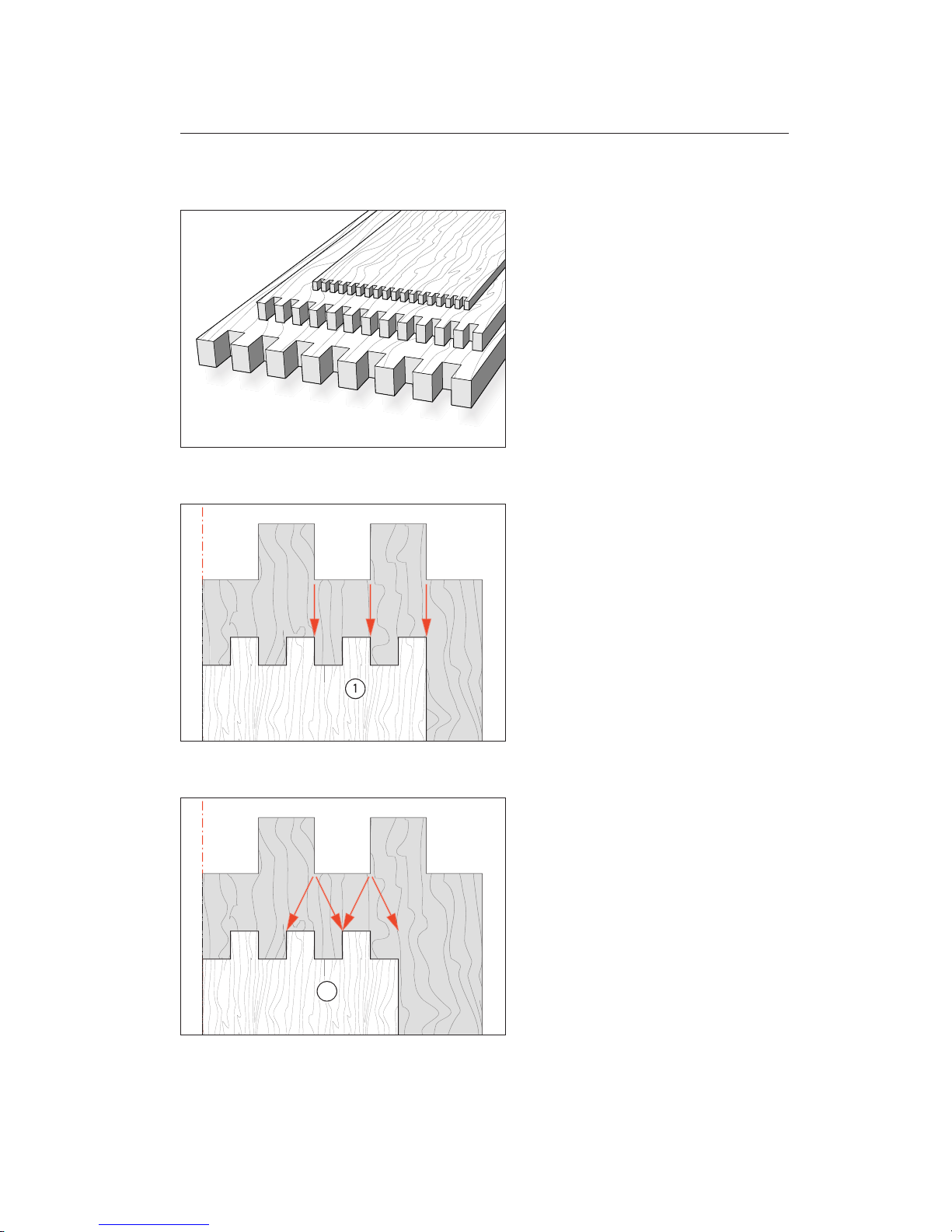
10-1 Small Box Joints
The template pin positions for square and
rounded finger joints are a quarter pitch
apart. This allows routing of half-size, even
quarter-size box joints (it does not work
on rounded finger joints). You get the
advantage of routing thicker, wider boards
with
1
⁄4
"[6mm] box joints on the
1
⁄2
"[12mm]
template; or as small as
1
⁄16"[2mm] on the
1
⁄4"[8mm] template. There are some specif-
ic rules for routing small box joints; see figures 10-2 to 10-7 starting below.
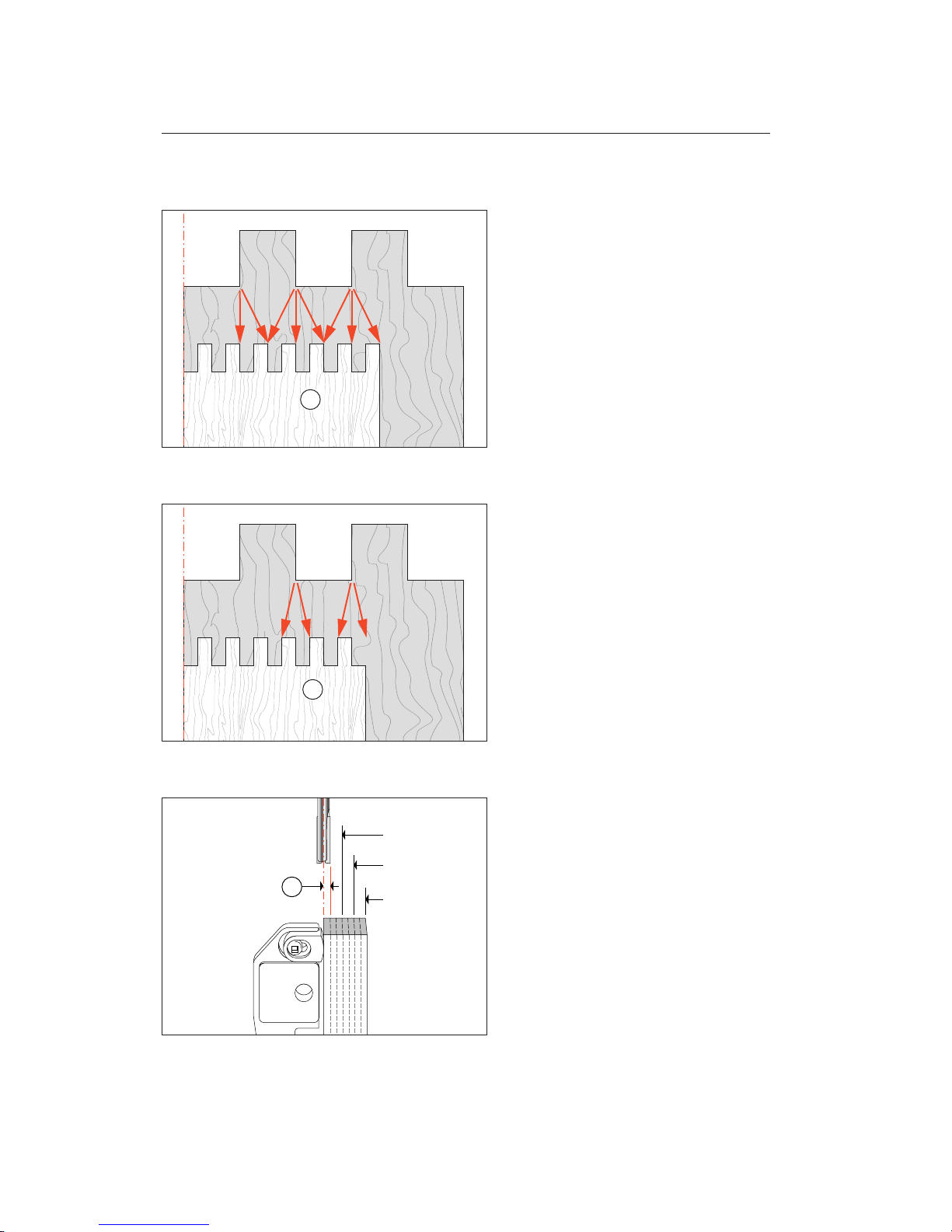
10-2 Board Widths For Small Box Joints
These widths have to be calculated (by
simple addition or subtraction) from the
board width charts on pages 37 and 38.
The simple calculation rules are:
Use any one of the board widths listed under
the selected comb size, with the following additions or subtractions.
Half-size asymmetrical
➀
: width as per
chart.
Note: The grey background in these four
illustrations represents the chart width.
10-3
Half-size symmetrical➁:
Chart width plus or minus diameter of small
cutter.
2
69
Page 76
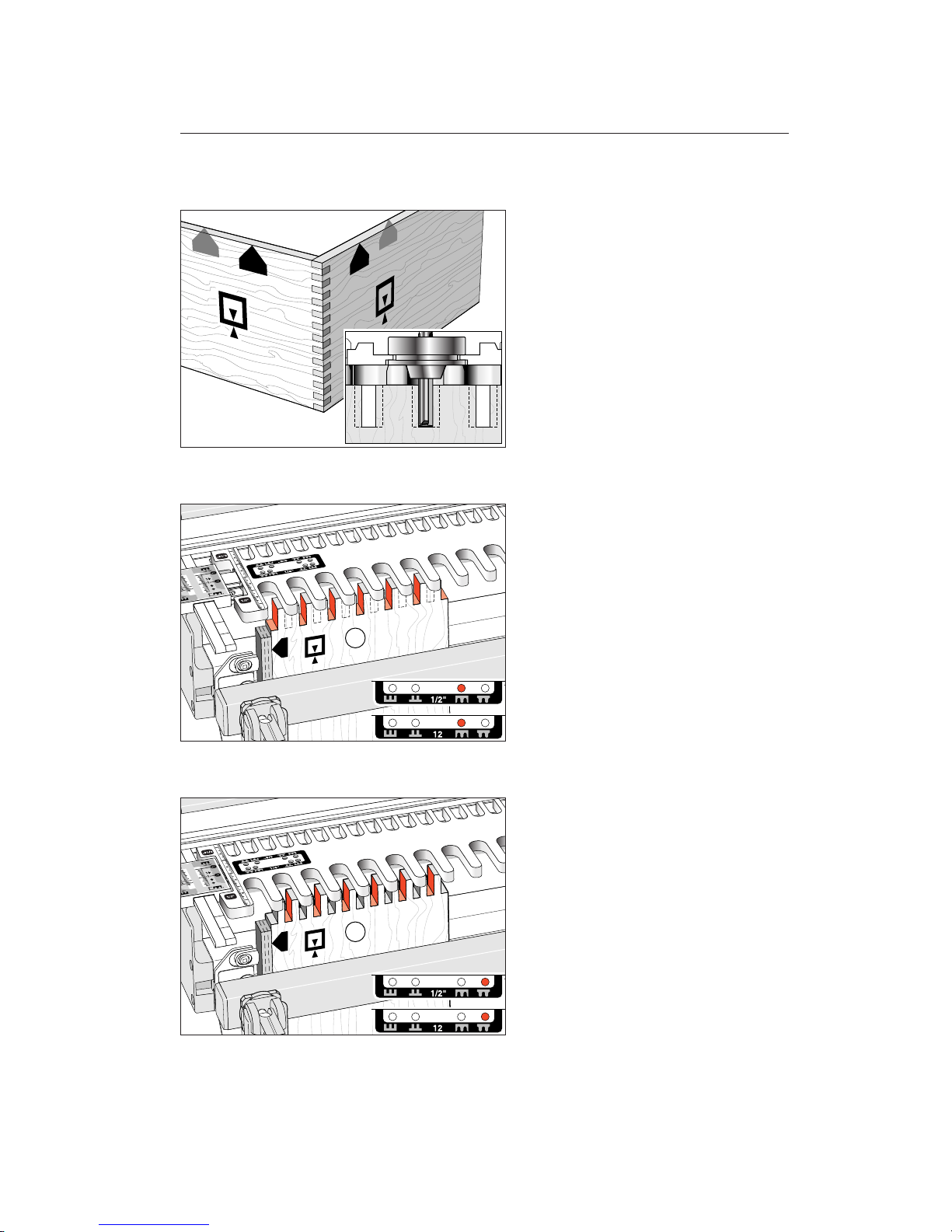
10-4
Quarter-size asymmetrical➂:
Chart width, or chart width plus or minus
two diameters of small cutter.
10-5
Quarter-size symmetrical➃:
Chart width plus or minus diameter of small
cutter.
10-6
Block away from side stops. If you used the
standard side stop positions for small box
joints, the side sockets or side fingers would
not be cutter sized. To ensure the correct
edge finish, it is necessary to block the board
away from the side stop by the radius of the
small cutter
➀
. Obviously this “block” (strip)
could be so small as to be difficult to make
and attach. So make up a block that is an
odd multiple (3x, 5x, 7x, etc.) of the cutter
radius.
3
4
1
3x Radius
5x Radius
7x Radius
SMALL BOX JOINTS
Chapter 10
70
Chapter 10 F1 User Guide
Page 77
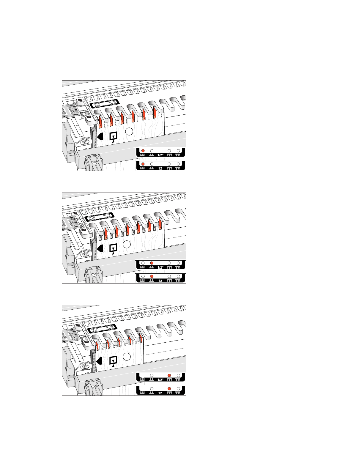
10-7 Box Joints Half the Nominal Size
E.g., 1⁄4
"[6mm] box joints on the
1
⁄2
"[12mm]
comb. Use the same size guide bush for the
selected comb, but use a cutter of half the
nominal size.
10-8
Put the template pin in setting E, rout the
half-size sockets but leave the board
➀
in
the clamp. Note: this example is a symmetrical joint, yours can be asymmetrical.
Also, depending on the actual size of the
side stop block, your number
➀
board edge
at the side stop may start with a pin instead
of a socket. It doesn’t matter, the mating
board will automatically match.
10-9
Move the template and put the template
pin in the setting
F
. Rout the other halfsize sockets and remove the board. This
board
➀
will now have fingers and sockets half the nominal size.
Repeat 10-8 and 10-9 on the other end
of the board
➀
and both ends of board ➂.
1
1
71
Page 78
10-10
Mount the mating board ➁. Put the template pin in setting
A
and rout the sock-
ets. Leave the board in place.
10-11
Move the template and template pin to setting
B
and rout the sockets. Fit the boards
together. You may need to adjust the VGS
to get the right fit.
Repeat 10-10 and 10-11 on the other
end of board
➁
and on both ends of board➃.
10-12 Box Joints a Quarter the Nominal Size
Mount board ➀. Use a guidebush of the
nominal size for the chosen comb, but use
a cutter one-quarter the nominal cutter
size. Rout board
➀
in the pitch setting
E
(as shown here) and in each of the other
pitch settings as follows without unclamp-
ing the board.
2
2
1
SMALL BOX JOINTS
Chapter 10
72
Chapter 10 F1 User Guide
Page 79
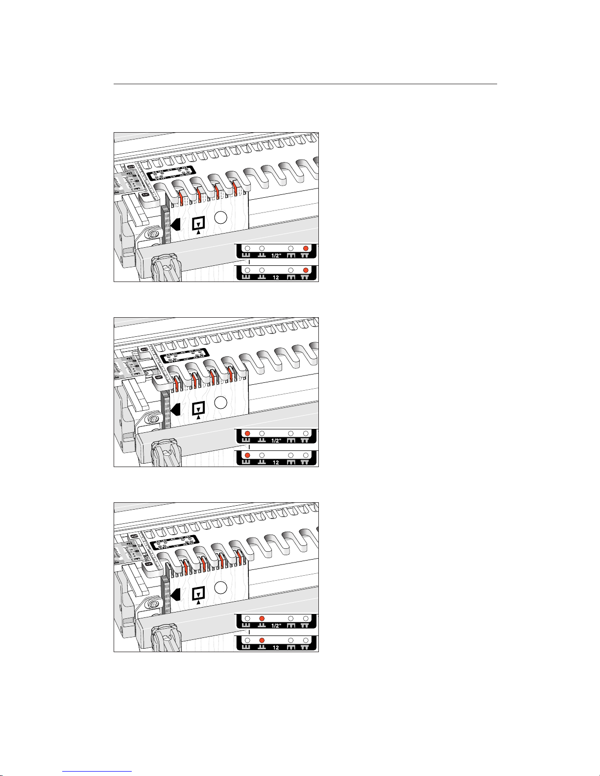
10-13
Pin position F.
10-14
Pin position A.
10-15
Pin position B.
Repeat 10-12 through 10-15 on the other
end of board
➀
and on both ends of board➂.
111
73
Page 80
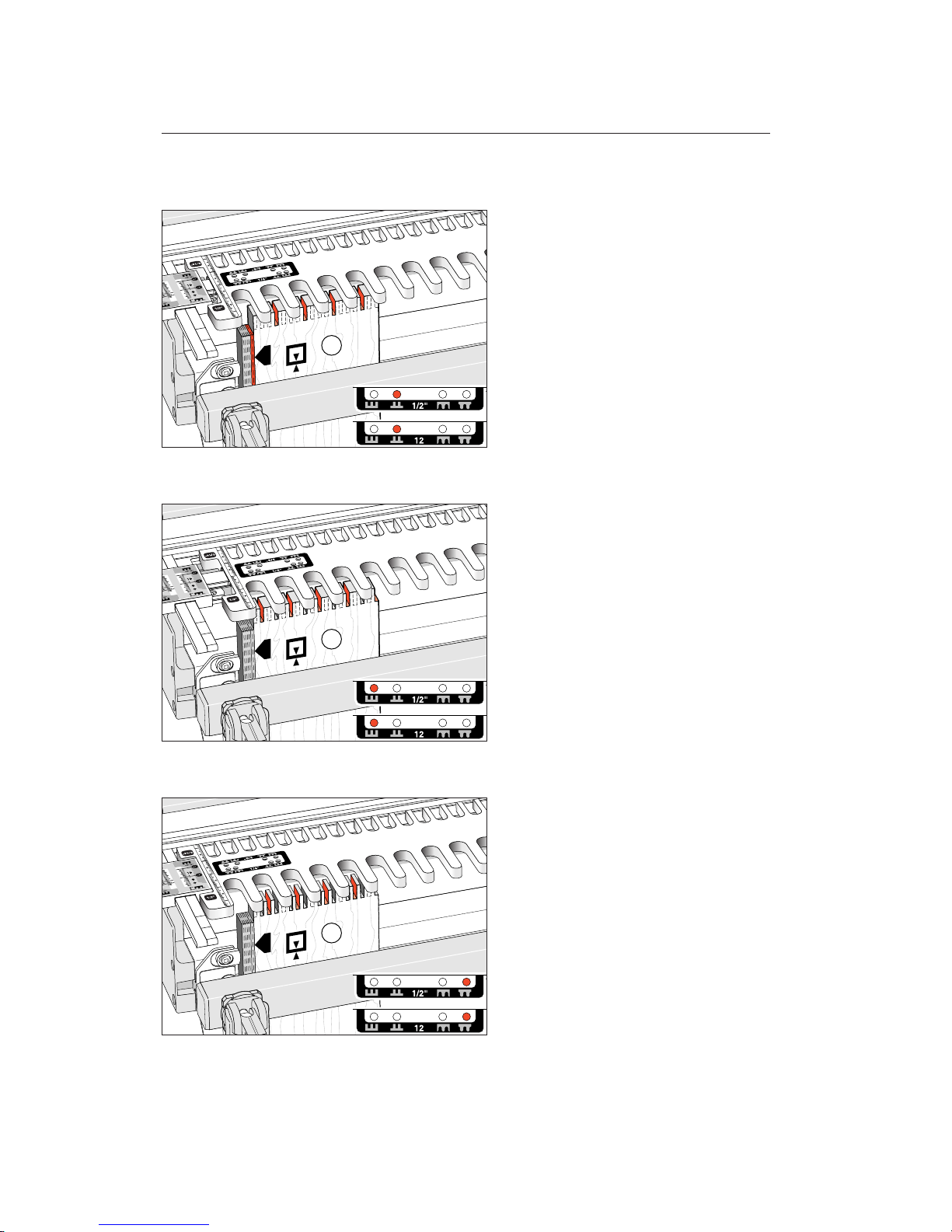
10-16
We have now run out of template offsets,
so to make the two boards mate flush at the
side edges we need to offset board
➁
by
one diameter of the small cutter, shown
here as a red block (See 10-20 for very small
joints). Rout board in all four pin positions,
here in
B
, then in...
10-17
...pin position A.
10-18
Pin position F.
222
SMALL BOX JOINTS
Chapter 10
74
Chapter 10 F1 User Guide
Page 81
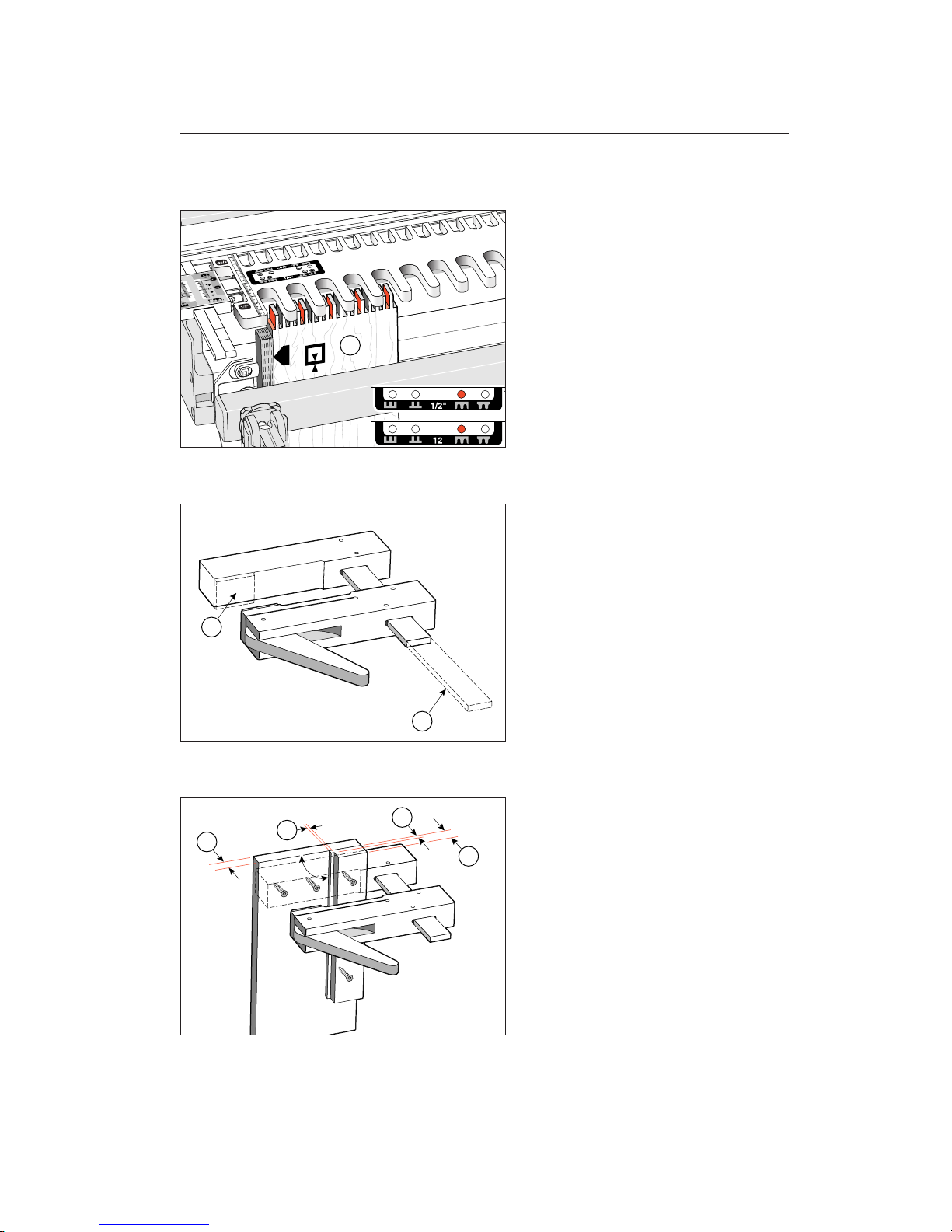
10-19
Pin position E.
Repeat 10-16 through 10-19 on the other
end of board
➁
and on both ends of board➃.
10-20
For very thin or short boards, make up an
auxiliary clamp with its own stepped side
stop by adapting a stock clamp. Remove
the grip pad
➀
flush to the fixed jaw face.
Remove the excess metal bar
➁
. These useful wooden clamps are generally available
from most good woodworking tool stores.
10-21
Rout up to four pieces at once, and speed
up small box joint routing. Adjust the
scale settings to allow for the backboard
thickness, e.g., a
1
⁄2"[12mm] backboard
➀
; move the template 1⁄2"[12mm]
further toward you.
➁
is a step, equal to
the small cutter diameter used.
➂
is
slightly less than one or two board
thicknesses.
➃
is greater than all board
thicknesses combined.
2
1
2
4
3
2
1
90
o
75
Page 82
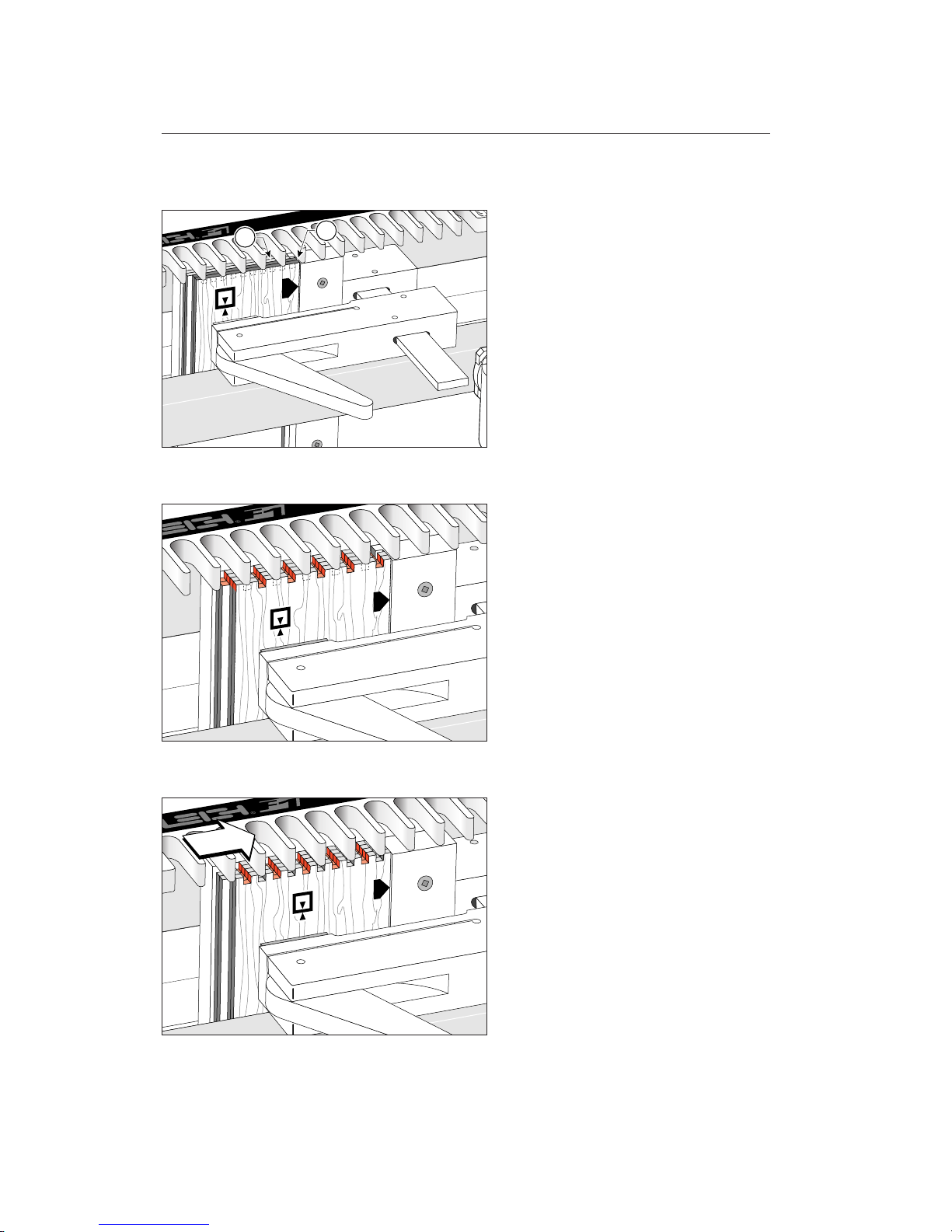
10-22
The front jig clamp holds the auxiliary
clamp by its stepped side stop. The small
boards may slide behind the jig front clamp
bar if necessary. The rear two boards
➀
are
offset from the front two boards
➁
by
the stepped side stop, at an amount equal
to the small cutter diameter used.
Adjust the auxiliary clamp left and right in
the jigs front clamp to allow for the correct
side edge finish.
10-23
In this example, a half-size joint is being
simultaneously routed in all four box board
ends. First in one pin position...
10-24
...then in the next.
1
2
SMALL BOX JOINTS
Chapter 10
76
Chapter 10 F1 User Guide
Page 83
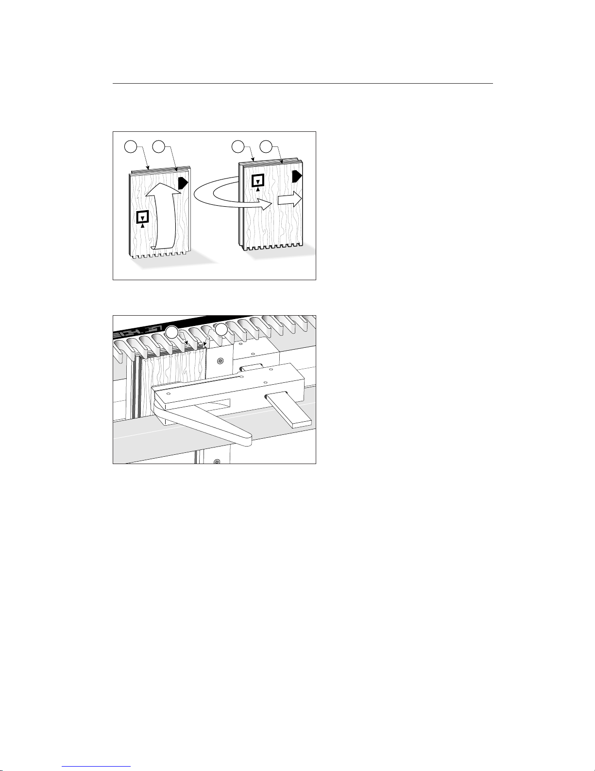
10-25
Remove all four boards together, and turn
end for end, keeping the same edges to the
side stop. Move boards
➁
back to the front
before re-clamping.
10-26
Now rout these four ends in the same two
template pin positions as before.
12 21
1
2
77
Page 84

SMALL BOX JOINTS
Chapter 10
78
Chapter 10 F1 User Guide
Page 85

Wider Box Joints
CHAPTER 11
Page 86

Chapter 11 F1 User Guide
WIDER BOX JOINTS
80
Chapter Foreword
Occasionally, you may need box joints that
are wider than the combs on the F1 Template.
Woodworker and Leigh Jig user Donald
Brown of Havana, Florida, sent us this good
idea on routing procedures for wide box
joints on the Leigh F1.
These instructions are based on the
assumption that you are fully conversant
with the use of the F1 Template and the
instructions in this User Guide. Do not
attempt the following procedures until
you are. Practice with scrap boards before
attempting to make a finished project.
Page 87
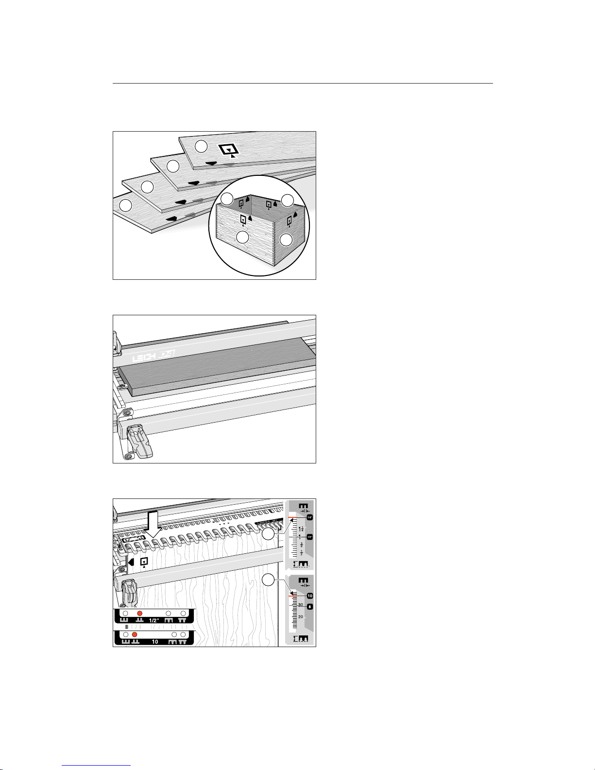
11-1
Refer to the extended board width charts
on page 84 to select the width and comb
size. Prepare four boards and mark them
1,2,3,4. Select the grain alignment and
mark the common top (or bottom) edges.
Don’t worry about face side selection,
this can be done after routing.
11-2
Replace the spacer board with a scrap backup board. This board needs to be flat and
even thickness like the spacer board and
have its front edge straight. It should be
long enough to extend past the end of the
active comb.
11-3
Lower the template onto the backup board
and set scales on the comb size to be used
(example here:
1
⁄2"[and 10mm] combs ➀).
Position the template with the template
pin in the
B
position. Clamp board No.
1 in the jig, side edge mark to side stop, top
end edge touching the underside of the
template. Make sure the horizontal scrap
board is touching firmly against the rear of
the workpiece.
2
1
3
2
1
3
4
4
1
1
81
Page 88
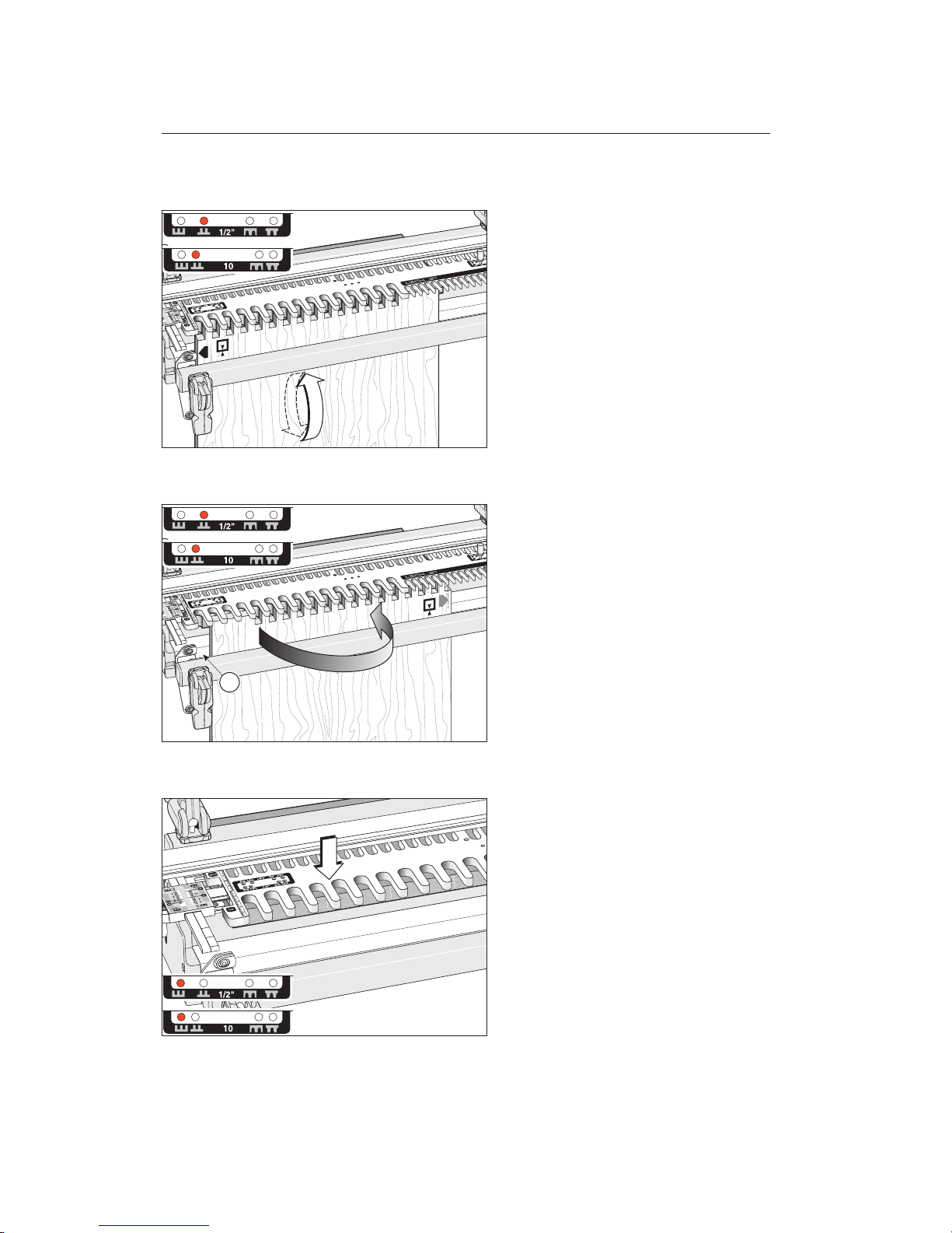
Chapter 11 F1 User Guide
11-4
Rout the full width of the active comb on
both ends of boards 1 and 3 in position
B
. Be sure to keep the same side edges to
the side stop.
Do not move or remove the backup board.
Remember: All square box joint boards (for
boxes or end-on-end joints) are clamped alternately face-in and face-out
j
.
11-5
Turn board No. 1, like turning the page of
a book so the side stop mark is now to the
right. Very carefully position and clamp the
board in the jig so the previously routed
sockets in the workpiece perfectly line
up with the routed sockets in the backup board. Keep the left edge of the board
away from the side stop
➀
. Rout the left
side of this end. Repeat this procedure to
complete the routing of the other end of
board 1, and both ends of board 3.
11-6
Move the template to position Aand
replace the backup board with a new cleanedged piece.
1
WIDER BOX JOINTS
82
Page 89
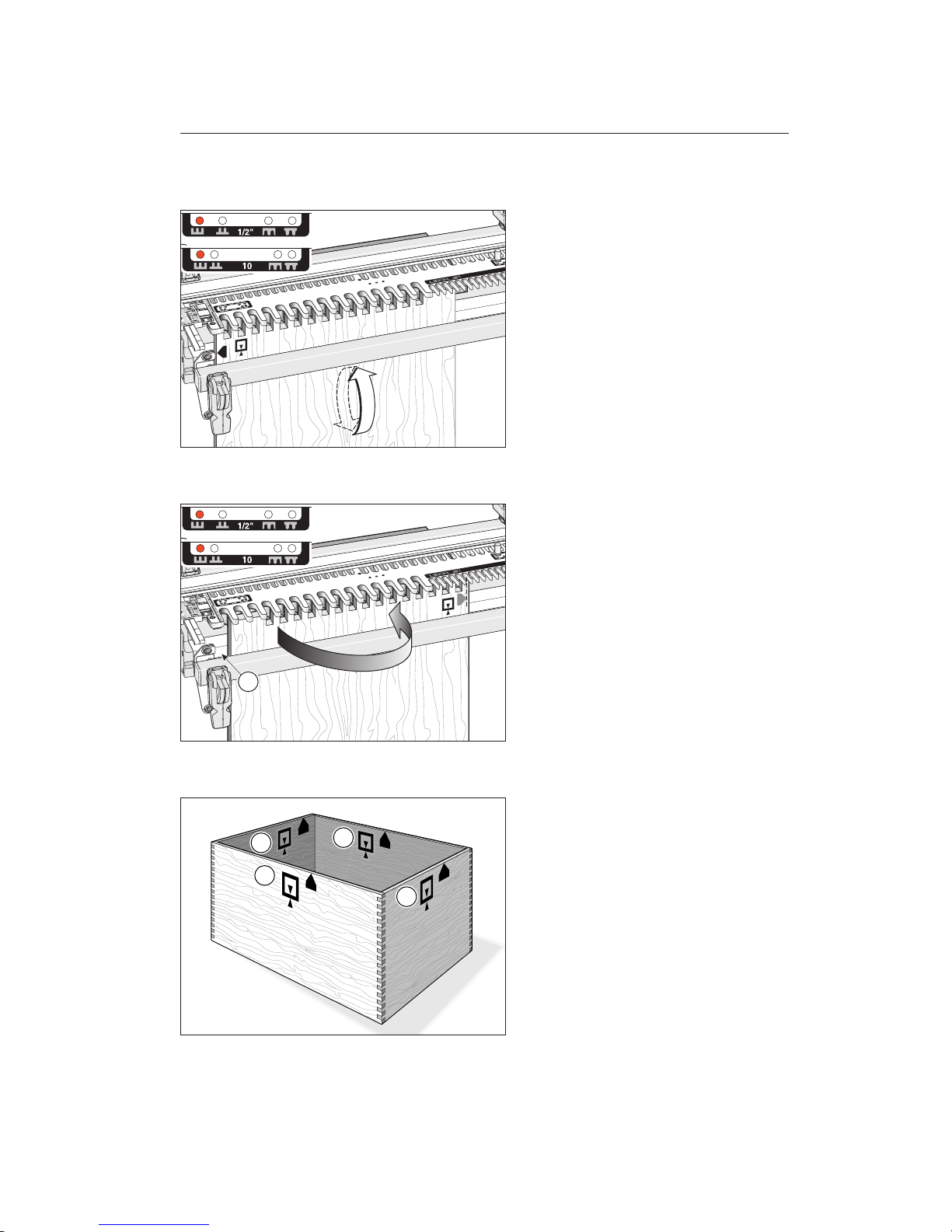
11-7
Rout both ends of boards 2 and 4, first routing both ends of each board against the the
left side stop, and then...
11-8
...reposition (as with boards 1 and 3) to
align and complete the routing. Keep the
left edge of the board away from the side
stop
➀
. Rout the left side of this end of
boards 2 and 4.
11-9
Keeping the marked side stop edges of all
boards toward the top (or bottom) of the
box, select the preferred outside faces of
the boards and assemble the box.
Remember; box joint corners need
clamping from both directions, or use
strap clamps and blocks.
1
2
1
3
4
83
Page 90
WIDER BOX JOINTS
84
Chapter 11 F1 User Guide
15.178
15
3
/
16
16.194
16
3
/
16
17.210
17
7
/
32
18.226
18
7
/
32
19.242
19
1
/
4
20.258
20
1
/
4
21.274
21
9
/
32
22.290
22
9
/
32
23.306
23
5
/
16
12.960
12
31
/
32
13.726
13
23
/
32
14.492
14
1
/
2
15.258
15
1
/
4
16.024
16
1
/
32
16.790
16
25
/
32
17.556
17
9
/
16
18.322
18
5
/
16
19.088
19
3
/
32
19.854
19
27
/
32
20.620
20
5
/
8
21.386
21
3
/
8
22.152
22
5
/
32
22.918
22
29
/
32
345
366
386
407
427
447
468
488
509
529
549
570
261
277
294
310
327
343
359
376
392
409
425
441
458
474
491
15.686
15
11
/
16
16.702
16
11
/
16
17.718
17
23
/
32
18.734
18
23
/
32
19.750
19
3
/
4
20.766
20
3
/
4
21.782
21
25
/
32
22.798
22
13
/
16
23.814
23
13
/
16
30
31
32
33
34
35
36
37
38
39
40
41
42
43
44
45
46
47
30
31
32
33
34
35
36
37
38
39
40
41
42
43
44
45
46
47
48
49
50
51
52
53
54
55
56
57
58
59
60
13.343
13
11
/
32
14.109
14
3
/
32
14.875
14
7
/
8
15.641
15
5
/
8
16.407
16
13
/
32
17.173
17
3
/
16
17.939
17
15
/
16
18.705
18
23
/
32
19.471
19
15
/
32
20.237
20
1
/
4
21.003
21
21.769
21
25
/
32
22.535
22
17
/
32
356
376
396
417
437
458
478
498
519
539
560
580
30
31
32
33
34
35
36
37
38
39
40
41
42
43
44
45
46
47
48
49
50
51
52
53
54
55
56
57
58
59
60
61
30
31
32
33
34
35
36
37
38
39
40
41
42
43
44
45
46
47
48
49
50
51
52
53
54
55
56
57
58
59
60
61
269
286
302
318
335
351
368
384
400
417
433
450
466
482
499
BOARD WIDTH CHART (INCHES and MM)
Use to the nearest 1⁄32" or
1mm for width selection.
To make symmetrical
square joints, use the board
widths in red. For asymmetrical square joints, use
the board widths in black.
Rounded joints cannot be
routed wider than the
dimensions on pages 37
and 38.
Numbers in white columns are the number of sockets and pins
Page 91

Hints and Tips
CHAPTER 12
Page 92

Chapter 12 F1 User Guide
HINTS AND TIPS
86
Chapter Foreword
Here are some special techniques and ideas
to help you get the most out of your
Leigh F1 Template.
Page 93
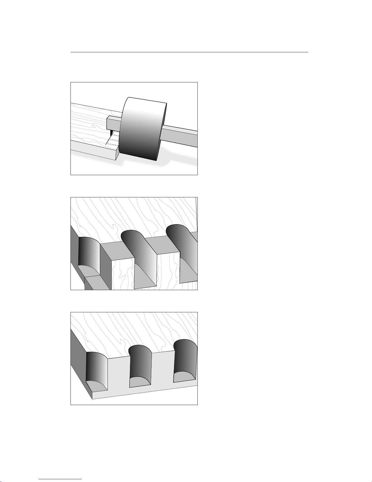
12-1
To prevent tear-out at the back bottom part
of the cut, scribe a line with your marking gauge across the back of the board at
exactly the depth of cut.
12-2
To help prevent tear-out on the sides of the
exit cut, back up the cut with a horizontal board end-grain pushed against the back
of the workpiece and held in the rear clamp.
12-3
This same scrap piece can remain in place
for successive cuts. If you have a variable
speed router, try changing the speed and
experiment with different feed rates.
87
Page 94
Chapter 12 F1 User Guide
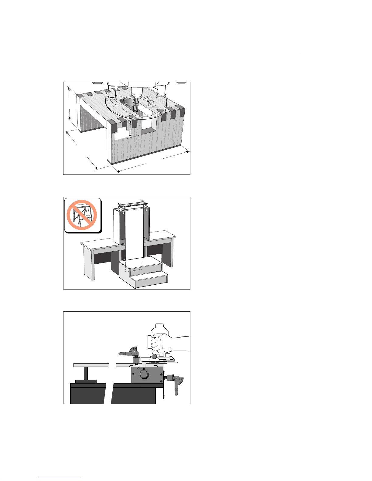
12-4
Router Stand: Make up a small router stand
as illustrated, to mount the router securely on the bench when not in use.
12-5
For routing long vertical boards it may be
necessary to build a jig stand to mount
securely on your bench. Make the stand
and bench height combination sufficient
to accept the board length you have in mind.
The jig stand should be bolted securely
to the bench. Make up a stable platform to
stand on as in the illustration. Do not use
a set of steps. Steps are not stable enough.
12-6
When placing long horizontal boards in
the rear clamp, make sure the rear end of
the board is supported to prevent unnecessary racking of the jig.
7"
[180mm]
3 1/2"
[90mm]
1
1
/
2
"
[40mm]
7"
[180mm]
HINTS AND TIPS
88
Page 95
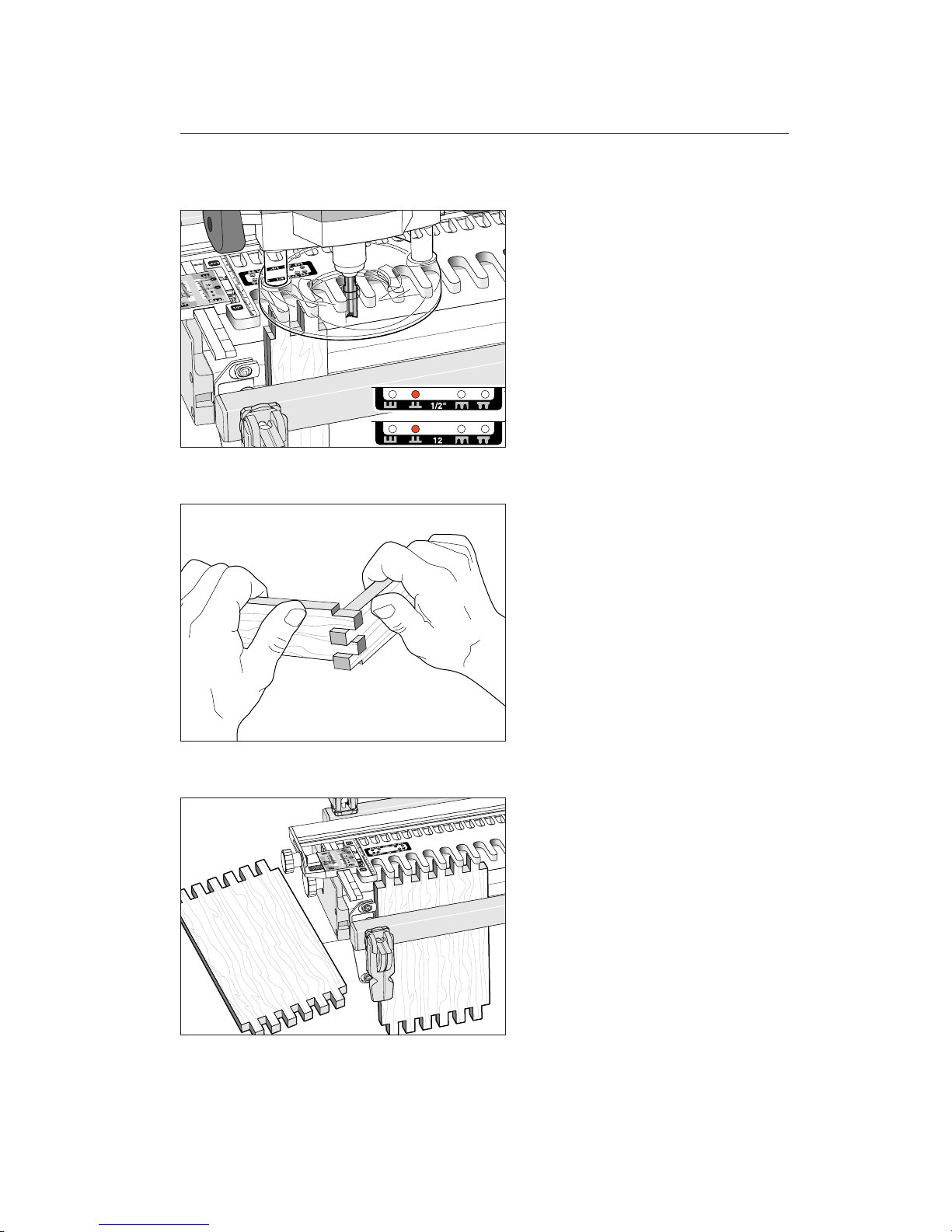
12-7 Quick Fit Test
Rather than routing test pieces separately,
here is a quick way to get 99% of the way
there. Simply rout two thinner boards of
scrap stock simultaneously. Any single pin
position will do, unless you intend to rout
small box joints, in which case, use the
matching pin positions described in chapter 10.
If you prefer, use one piece and saw in half
after routing.
12-8
Test for fit. Don’t worry about board alignment, it’s only the fit you’re testing. Adjust
the VGS by trial and error and rout more
pairs of scrap board ends as required.
12-9
Once you have a good fit, rout a complete
pair of separate test pieces in the same species
wood as the actual workpieces, to test for
final fit.
89
Page 96

HINTS AND TIPS
90
Chapter 12 F1 User Guide
Page 97
Variable Guidebush Selection
APPENDIX I
Page 98

Chapter Foreword
VGS: The Leigh Variable Guidebush System
The VGS is included with the F1 Finger
Joint Template but you may need an option-
al adaptor for your router (see next pages).
Do not use the VGS on D Series dovetail jigs or the M2(MMTA) as the tapered
VGS bushes will not index properly on
the guidefingers and guide rails.
VARIABLE GUIDEBUSH SELECTION
Appendix I F1 User Guide
92
Page 99
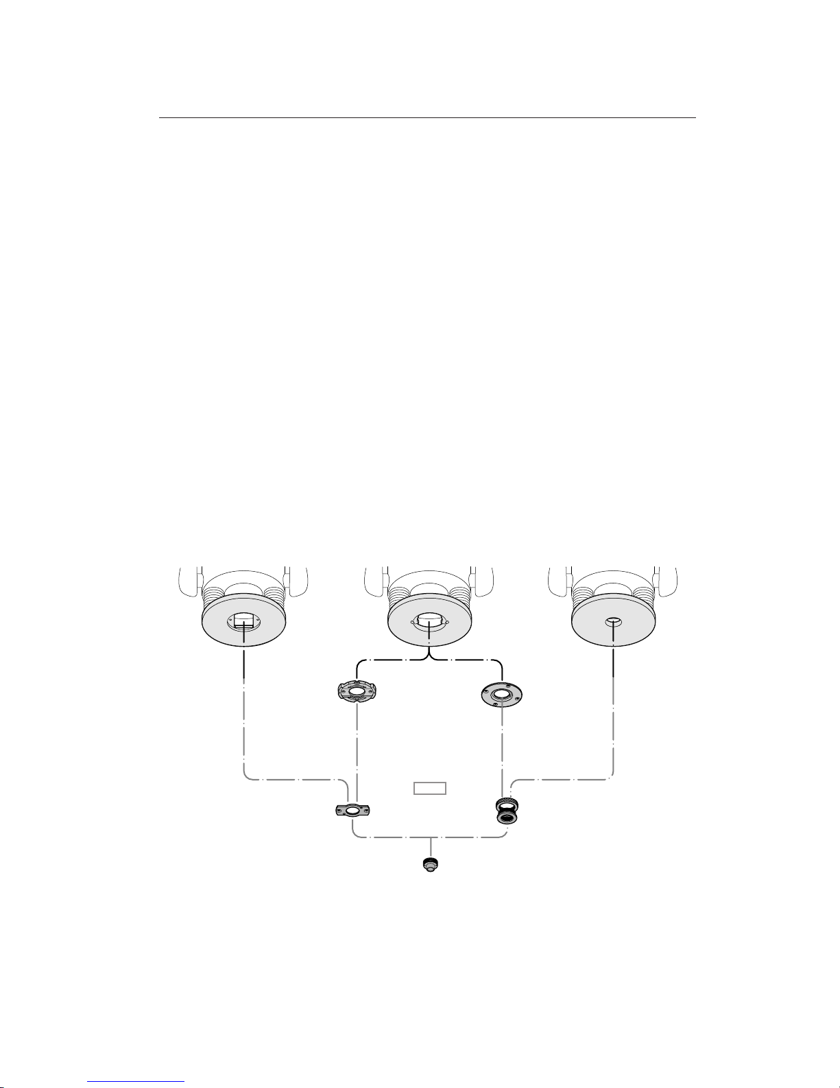
93
701V
702
703
705
702
703
704
707
700V
709V
711V
713V
716V
BLACK &
DECKER
DEWALT
ELU
PORTER CABLE
BLACK & DECKER
ELU
HOLZ-HER
ISKRA
KANGO
KRESS
PERLES
SCHEER
STAYER
WEGOMA
BOSCH
CASALS
DEWALT
ELU
FESTO
FREUD
HITACHI
HOLZ-HER
JEPSON
MAFELL
MAKITA
METABO
RYOBI
SKIL
The Vital Link Between Your Router and the
Leigh F1 Template
Because there is little or no standardization in
the router industry, Leigh has developed a comprehensive guidebush and adaptor system to
match your router to Leigh jigs and attachments.
The diagram below shows how the VGS parts
relate to each other and to different makes and
types of routers.
Do not use this diagram for part selection. See
pages 94 and 95.
The Variable Guidebush System
*Note: 709V is not included in “metric” F1 Template.
*
Page 100
VARIABLE GUIDEBUSH SELECTION
Appendix I F1 User Guide
94
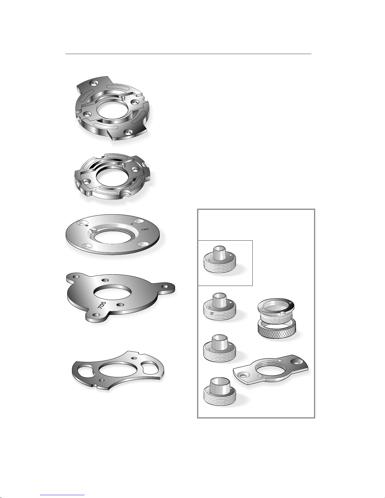
How to Select the Adaptor for The Leigh F1
Template and Variable Guidebush System
1. Go to the Selection Chart on the facing
page.
2. Find the make and model of your router
from columns 1 and 2.
3. See which standard variable guidebush holder works with your router
in column 4. This holder is includ-
ed with your F1.
4. Select the Adaptor for your router (if
required) from column 3. NA means not
available for those model routers. Leigh
does not stock router manufacturers’ adaptors.
Adaptor
No. 704
Adaptor
No. 705
706
CANADA
711V
709V*
713V
716V
701V
Adaptor
No. 706
Adaptor
No. 702
Adaptor
No. 703
700V
These accessories are included with the
F1 Template, except bush 709V* is not
included with the metric F1.
 Loading...