

Page 1
For the Leigh D4R Pro Dovetail Jig
Leigh Router Joinery Jigs
Dedicated Customer Support
1-800-663-8932
Joining Tradition with Today
Page 2

ii
D4R Pro User Guide
CONTENTS AND STANDARDS
Contents and Standards ........................................................ii
Chapter 1 Jig Assembly, Mounting, and Using The Clamps .................1
Chapter 2 Adjusting the Finger Assembly ............................................. 7
Chapter 3 The Leigh e-Bush and Optional Guidebushes ......................9
Chapter 4 Basic Jig Functions and Scale Modes ..................................11
Chapter 5 Using Your Jig Safely ...........................................................13
Chapter 6 Wood Preparation ...............................................................15
Chapter 7 Router Preparation ..............................................................17
Chapter 8 Through Dovetails ...............................................................19
Chapter 9 Large and Small Through Dovetails ....................................29
Chapter 10 Variably Spaced Half-Blind Dovetails .................................31
Chapter 11 Single Pass Half-Blind Dovetails .........................................39
Chapter 12 Rabbeted Half-Blind Dovetails ............................................ 45
Chapter 13 End-on-End Dovetails .......................................................... 47
Chapter 14 Asymmetric Dovetails .........................................................49
Chapter 15 Box Joints .............................................................................53
Chapter 16 Sliding Dovetails .................................................................. 59
Chapter 17 Hints & Tips ..........................................................................65
Appendix I Attaching the Leigh e-Bush to the Router .......................... 69
Appendix II Bit Selection .........................................................................71
Appendix III Jig Parts ................................................................................79
Appendix IV Customer Support ...............................................................83
Page 3
CONTENTS AND STANDARDS
1
2
Your New Leigh D4R Pro Dovetail Jig
Congratulations! You now own the world’s most useful and versatile dovetailing tool. The Leigh D4R Pro Dovetail
Jig will help you rout an infinite variety of joints, and all of its major functions are described in detail in this guide.
A very helpful DVD is also included, but the guide is essential reading.
D4R Pro User Guide
iii
We recommend that you first assemble and mount the jig,
carefully following the instructions in the first section of the
guide. Then read the rest of the guide, following along with the
basic functions and principles of operation, before you try to
do any actual joinery routing. By all means, rout a few practice
joints in scrap boards before you use the jig to rout a precious
hardwood workpiece!
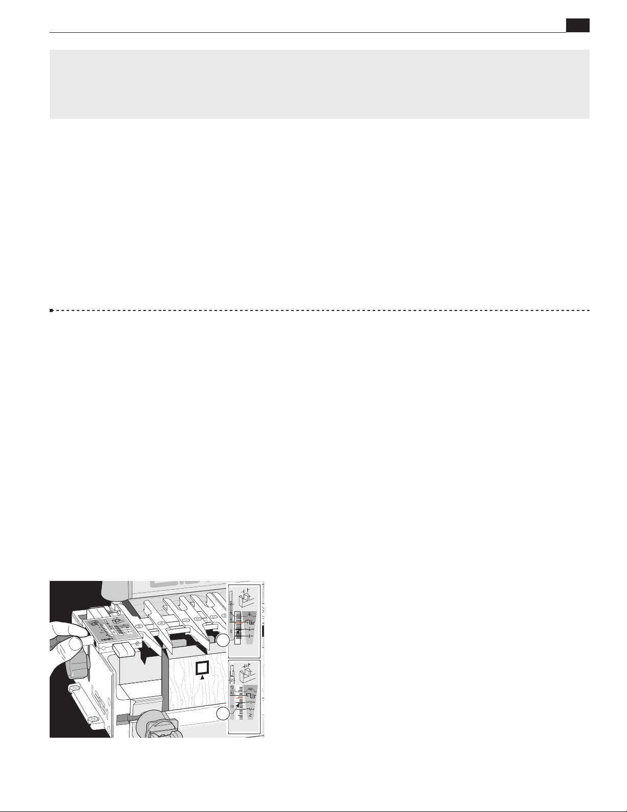
Important! Inches and Millimeters
The D4R Pro jig can be ordered in inch or metric versions.
They’re identical except for the calibration scales. This Leigh
English-language user guide shows measurements in both inches
and millimeters, with “inches” first, followed by “millimeters”
in square brackets.
3
Example:
⁄4"x 51⁄2"x 8" [20x 140x200mm]
If you have any questions that are not answered in this guide,
please contact Leigh customer support:
Tel: 1-800-663-8932 email: [email protected]
But remember: “If at first you don’t succeed, read the instructions!”
*See Appendix IV – Customer Support
Do not be concerned if the inch/millimeter equivalents are not
exact. Just use the dimensions which apply to your jig.
To simplify the instructions, most jig illustrations show a jig
considerably shorter than the standard 24"[610mm].
Where finger assembly scales overlay an illustration, the “inches”
scale will be at the top, and “millimeters” scale at the bottom. Only the right hand “active” half of the scales are illustrated.
For clarity, setting positions are indicated with a red line in the
guide only. On the jig, the lines are black.
Page 4
iv
2
3
D4R Pro User Guide
Glossary of Symbols
To help you understand the instructions and illustrations in this
manual, we have used a number of international symbols, plus
a few special ones of our own. They are all explained below. You
needn’t worry about memorizing these symbols now, because
they are repeated quite frequently in this user guide, and you
will soon get used to them.
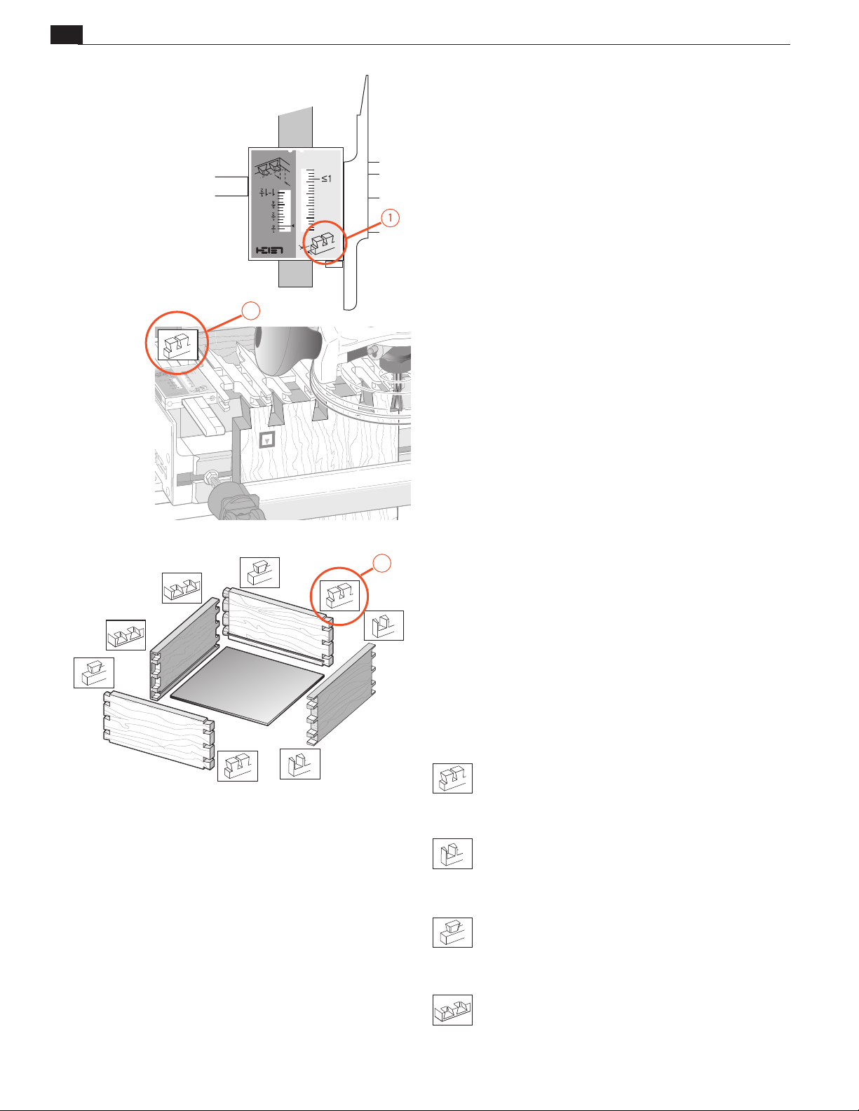
The Leigh jig’s guidefinger assembly can be in any one of four
joint modes, depending on what type of joint and which part
of the joint you are routing. Each finger assembly scale has it’s
own mode icon
will also find the joint mode icon in the top left corner of most
illustrations
CONTENTS AND STANDARDS
, identifying the joint part being routed. You
, indicating which finger assembly mode to use.
Sometimes a joint mode icon will be used to identify a board
.
These are the four joint mode icons:
TD Tails
(tails for through dovetail joints)
TD Pins
(pins for through dovetail joints)
HB Tails
(tails for half-blind dovetail joints)
HB Pins
(pins for half-blind dovetail joints)
Page 5
CONTENTS AND STANDARDS
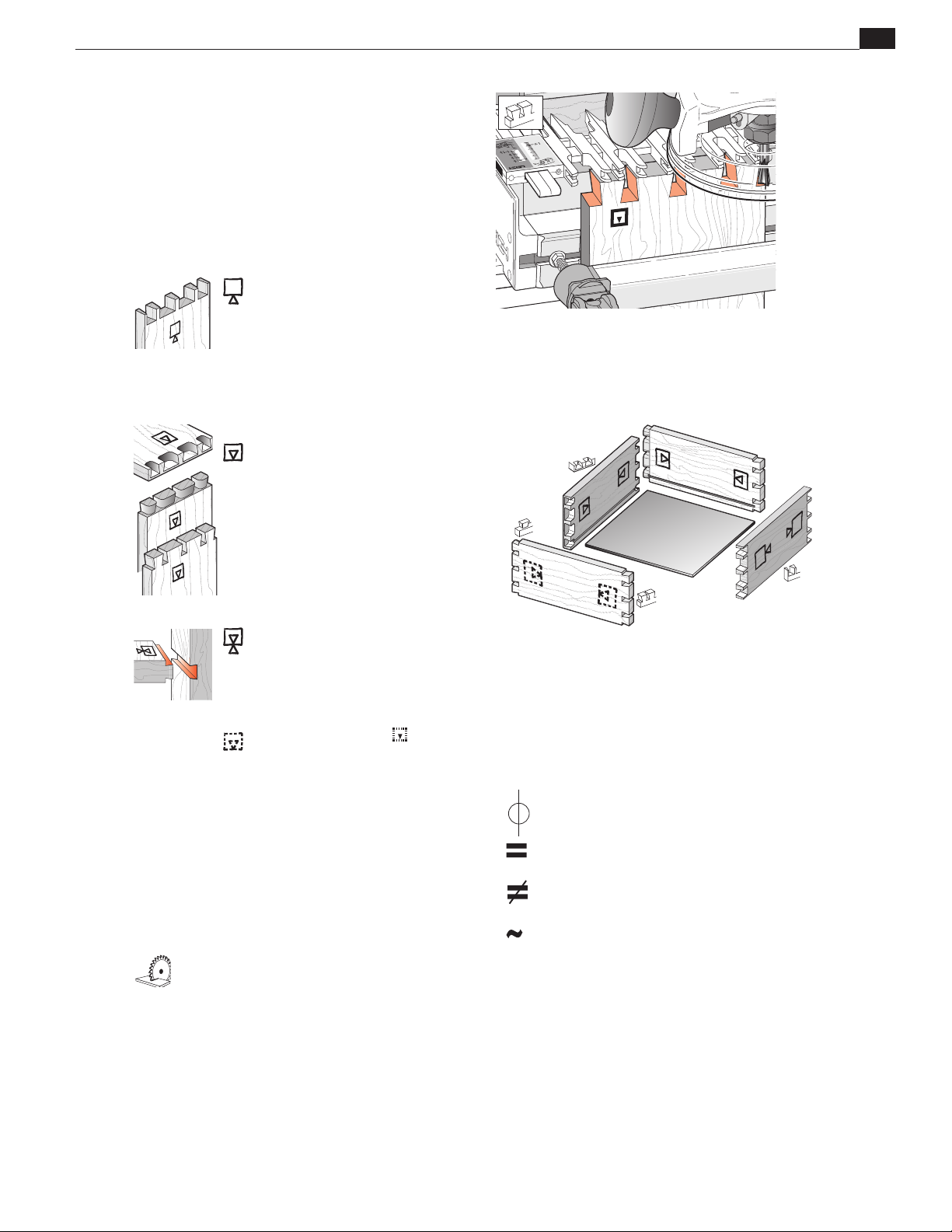
Which Way Round Should the Board Go?
As virtually all dovetail joinery is used to make boxes,
drawers and chests etc., we devised these simple (and
hopefully intuitive) icons to indicate which side of a
board faces inwards or outwards on the finished “box”,
and which side of the board faces outward (toward
you, the operator), when it is clamped in the jig.
D4R Pro User Guide
This icon o indicates the
“outside” of a board. All
through dovetail pin boards
are mounted in the jig with
this “outside” face away
from the jig (toward you, the
operator).
This icon i indicates the
“inside” of a board. All halfblind pin and half-blind tail
boards, and through dovetail
tail boards, are mounted in the
jig with the “inside” face away
from the jig toward you, the
operator.
v
This icon j indicates boards
that are mounted both ways
e.g. sliding dovetails and endon-end dovetails.
Dotted line icons
the “other” side of the board
in the illustrations.
The following symbols indicate:
This edge against sidestop
e
This edge against sidestop
f
Sawcut allowance
Caution: use special care for this
operation
Numbered References in text
indicate
Centerline of board or layout
Equals
Does not equal
Approximately
Page 6

vi
D4R Pro User Guide
CONTENTS AND STANDARDS
Add Leigh Accessories to make your jig even more versatile.
Finally, Dust-Free Routing
and Superb Router Support!
A must-have! The VRS Vacuum & Router
Support* is the ultimate dust and chip col-
lector. As an added bonus, the VRS adds full
width router support to your D4R Pro. It’s
simple to attach and the collector adapts to
most popular vacuum hose sizes.
Item VRSD24
* US patent: USPN 7,507,060 B2
UK patent: GB2446909
Leigh Brand Bit Sets Offer Great
Savings...and the Box Is Free!
Save over individual bit prices. Each top quality
bit set includes a box with foam insert that
accepts all shank sizes, and a handy bit chart in
the lid to list out all the bit specs.
Item 1607-8 7-piece Bit Set
Item 2411-8 12-piece Bit Set
Item 5116-8 15-piece Bit Set
Visit www.leighjigs.com for more details
Combine the VRS with a Bit Set
for Exceptional Savings!
The D4R Pro Accessory Kit is the best deal going.
Enjoy great savings on the 12-piece Bit Set and
even greater savings when you combine it with
the VRSD24 Vacuum & Router Support.
Item ACD24
Page 7
CONTENTS AND STANDARDS
D4R Pro User Guide
Optional Leigh Templates and Attachments
Precise, Easy Finger Joints
Finger joints are very strong, aesthetically
pleasing and easy to produce. Add an
F3 Finger Joint Template* to your D4R Pro
Jig and rout perfect finger joints in minutes.
3
Rout Box Joints from
Item F3
* US Patent No. 5,711,356
Canadian Patent No. 2,146,834
European Patent No. 0698458
/32" to 1".
Six Unique Isoloc Joints,
Only from Leigh
The patented Isoloc joint gives any corner
joint a very unique look. These one-of-a-kind
patterns will really set your woodworking
pieces apart from the rest. Great savings
when you buy all three templates.
Items I1A, I1B, I1C and I13 (3 pack)
vii
Need a Helping Hand?
Use Leigh Hold-Down Clamps
Leigh Hold-Down Clamps are tough, versatile and
immensely strong! They employ proven cam-action
technology developed for the award-winning Leigh
jigs, the D4R Pro and FMT. Bench clamps can be used
in any size hole and surface clamps can be mounted
on any flat surface, both on any angle. You can never
have too many clamps!
Item BHDC1 Bench Mount
Item SHDC1 Surface mount
Classic Multiple Mortise
and Tenon Joints that Last
The Leigh M2 Attachment is the only one of
its kind. The multiple mortise and tenon joint
is ideal for “shelf to upright” construction
and produces extremely strong joints that
stand the test of time.
Item M2
Visit www.leighjigs.com for more details
Page 8

viii
D4R Pro User Guide
Mortise & Tenon Joints have never been easier!
CONTENTS AND STANDARDS
Leigh Super FMT
Mortise & Tenon Jig
Item SFMT
Rout mortises and tenons in 60 seconds! Leigh Jigs make it easy:
One bit, one guide, one setup for perfect joints every time. Make
tables, chairs, beds, chests, cabinets and so much more!
Visit www.leighjigs.com for more details
Leigh FMT Pro
Mortise & Tenon Jig
Item FMT Pro
JIG FEATURES
• 21 standard joint sizes
• Hundreds of optional sizes
• 68 mortise & tenon sizes
• 6 specialty guides: Four square tenon
guides, louver guide set, Y-axis mortise
guide
• Maximum 1/2" x 5" joint size
• Single, double (tandem and side-byside), triple, quadruple joints
• Recordable, repeatable fit adjustment
• Angled and compound angled joints
• Works with virtually any plunge router
• Heavy gauge steel frame (Super FMT)
• CNC machined alumin. frame (FMT Pro)
• Multi-position clamping
• Clamp boards up to 3"x 5"
• Easy and precise joint sighting
STANDARD EQUIPMENT
• Universal sub-base that attaches to
virtually any plunge router
• Two F-Clamps (Super FMT); Cam-action
speed clamps (FMT Pro)
• Joint guide stand
• 5/16" HSS spiral upcut bit, 1/2" shank
• Two outrigger bars (FMT Pro only)
• Adjustable sidestop fence for tenoning
• Screwdrivers and mounting hardware
• Illustrated user guide
Page 9
D4R Pro - CHAPTER 1
Jig Assembly, Mounting,
and Using the Clamps
Make Sure You Have All the Parts.
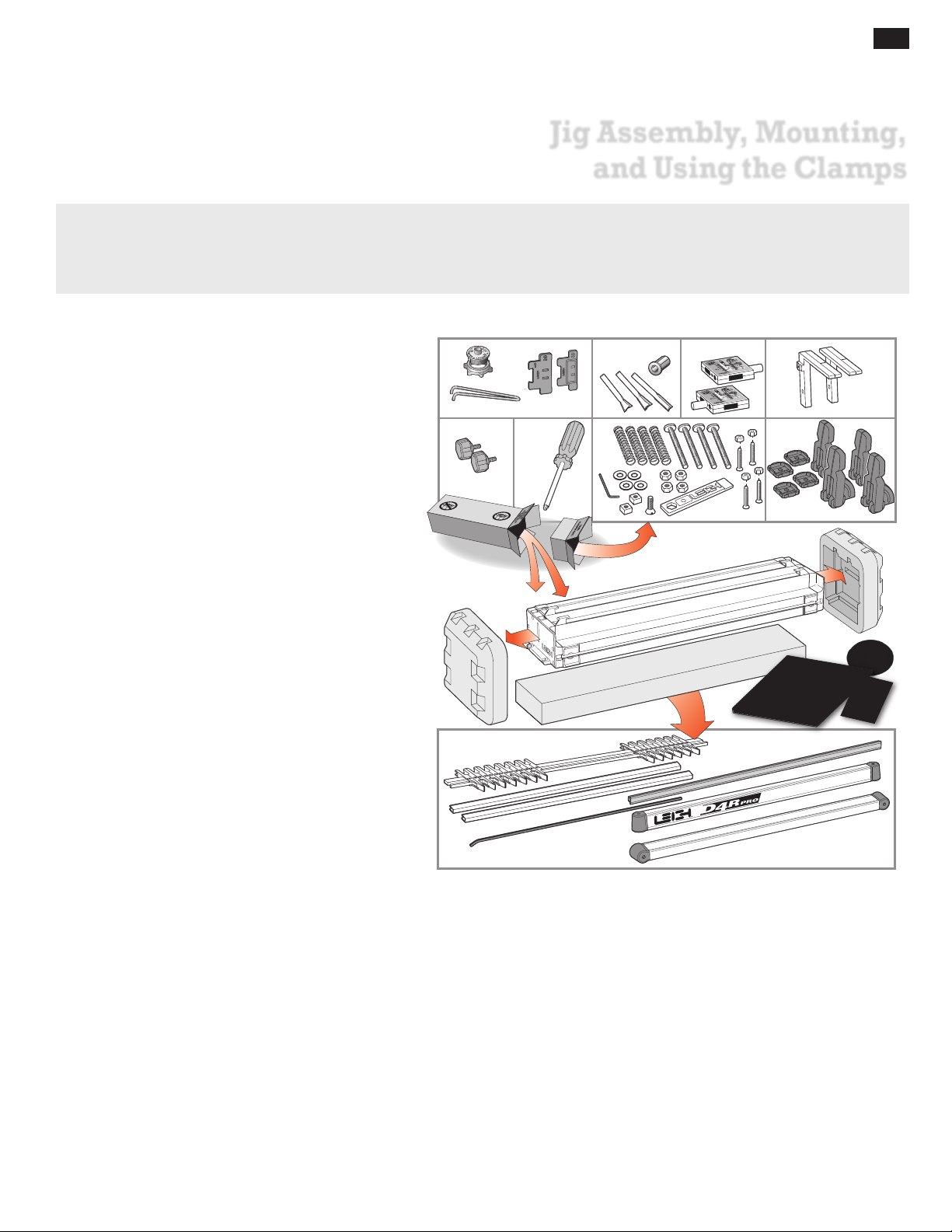
Before you start to assemble your Leigh D4R Pro, check to make sure you have received all the required parts.
1
The small carton you removed from the end of the main
carton contains:
1. 1 Leigh e7 Elliptical Guidebush & Pin Wrench
2 Spacers
2. 2 Dovetail bits, 1 straight bit, 1 Collet Reducer,
2 scale assemblies
3.
4. 2 support brackets
5. 2 support bracket knobs
6. Square-head guide finger screwdriver
7. 4 clamp springs
4 clamp T-bolts
4 flat washers
4 T-bolt nuts
2 square nuts
1 5⁄64" hex key
1 flat head machine screw
1 Leigh wrench/gauge
4 Jig Hold-down Nuts & Machine Screws 1⁄4"-20
4 cam-action speed clamps
8.
4 cam clamp step washers
…and any other small optional items you may have ordered
with your new jig. Check the packing slip for this information.
1 2 3 4
5 6 7 8
9
10
The main carton contains:
1 main jig body
9.
1 Leigh jig User Guide
Warranty/Registration Card
DVD instructional video (English only)
The large inner box contains:
1 finger assembly on 2 bars
10.
D4R Pro has 26 guidefingers (13 pairs)
2 lengths bridge extrusion
1 cross cut fence
1 nylon Stop Rod
2 clamp bars
If any items are missing from your jig, contact your supplier
or Leigh Industries immediately.
See Appendix IV - Customer Support.
Important Note
Mount your jig securely and assemble it completely before you try to
use it.
Make sure you have read and understood all the material in the Safety
section of this user guide before using the jig.
Page 10
2
Chapter 1 D4 R Pro User Guide
"[745mm]
5
16
/
29
1
35/16"[84mm]
1"[25.4mm]
JIG ASSEMBLY, MOUNTING, AND USING THE CLAMPS
37"[940mm]+
6"[150mm]+
4
2
3
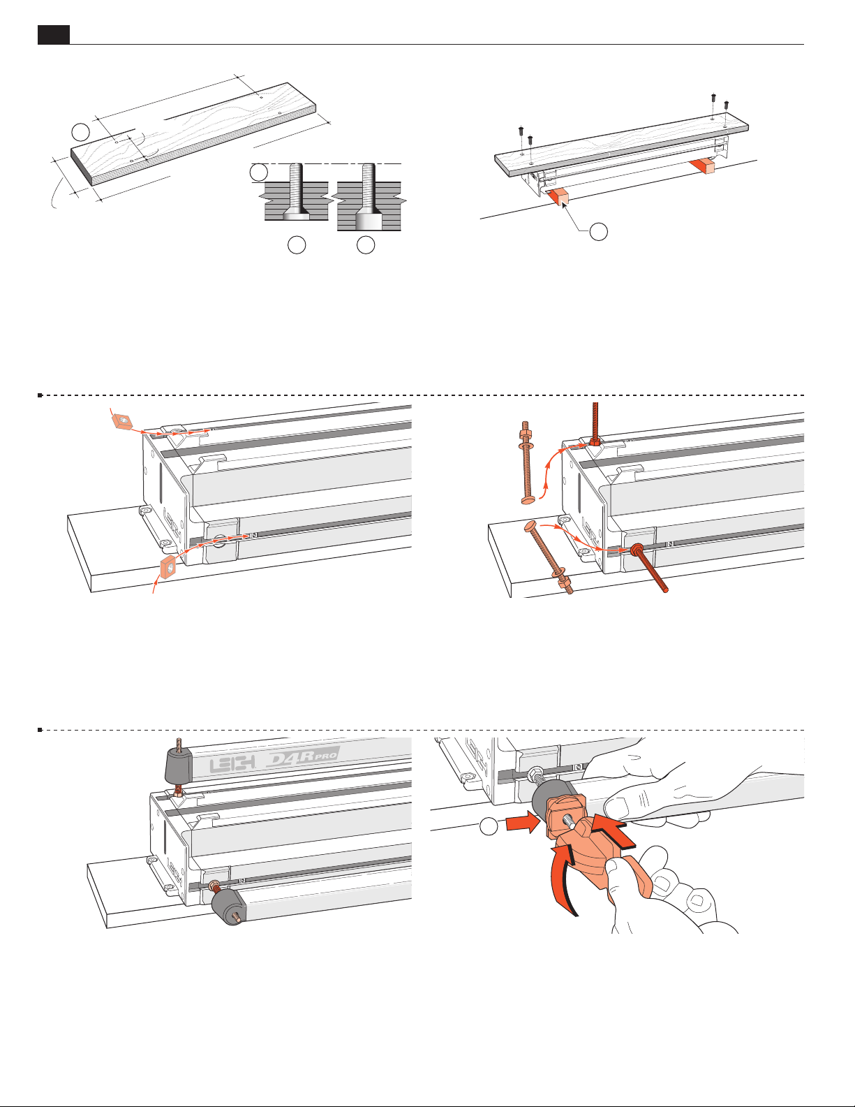
1-1 Prepare a flat board at least 3⁄4"[20mm] thick, and a mini-
9
mum of 37"x6"[940x150mm]. Drill four
⁄32"[7mm] holes on
29 5⁄16"x 3 5⁄16"[745x84,2mm] centers, 1"[25.4mm] in from the
front edge of the board . Countersink or counterbore the
underside if the board is thicker, so that the four 1⁄4-20x1" long
3
machine screws will project above the top surface by
⁄8"[9,5mm] .
1
1-2
Turn the jig body upside-down on two blocks (to protect
the side stops). Using the four nuts and four countersunk machine
screws, bolt the base board to the jig using the two nut recesses in
each end housing. Holes drilled 1"[24mm] from the front edge
of the board go to the front of the jig. Now you can clamp your
D4R to any bench.
1-3 With the jig right side up, insert one square nut (part #284)
into each of the channels in the main extrusion. These nuts are
for possible future attachment of accessories. See Chapter 9.
1-5 Place four springs and two clamp bars on the T-bolts.
Make sure the clamp bars move freely on the T-bolts.
1-4 Insert the four clamp T-bolts into the T-slots (two at each
end of the jig). Position so that the washers seat into the round
milled recesses. Tighten the four clamp bolt nuts with the Leigh
wrench.
1
1-6 Place one black step washer on each T-bolt with the
flat side against the clamp bar. Screw a clamp lever assembly onto
each T-bolt, making sure the cam lobes are between the step
washer sidewalls.
Page 11
JIG ASSEMBLY, MOUNTING, AND USING THE CLAMPS
1
90˚
Chapter 1D4 R Pro User Guide
2
3
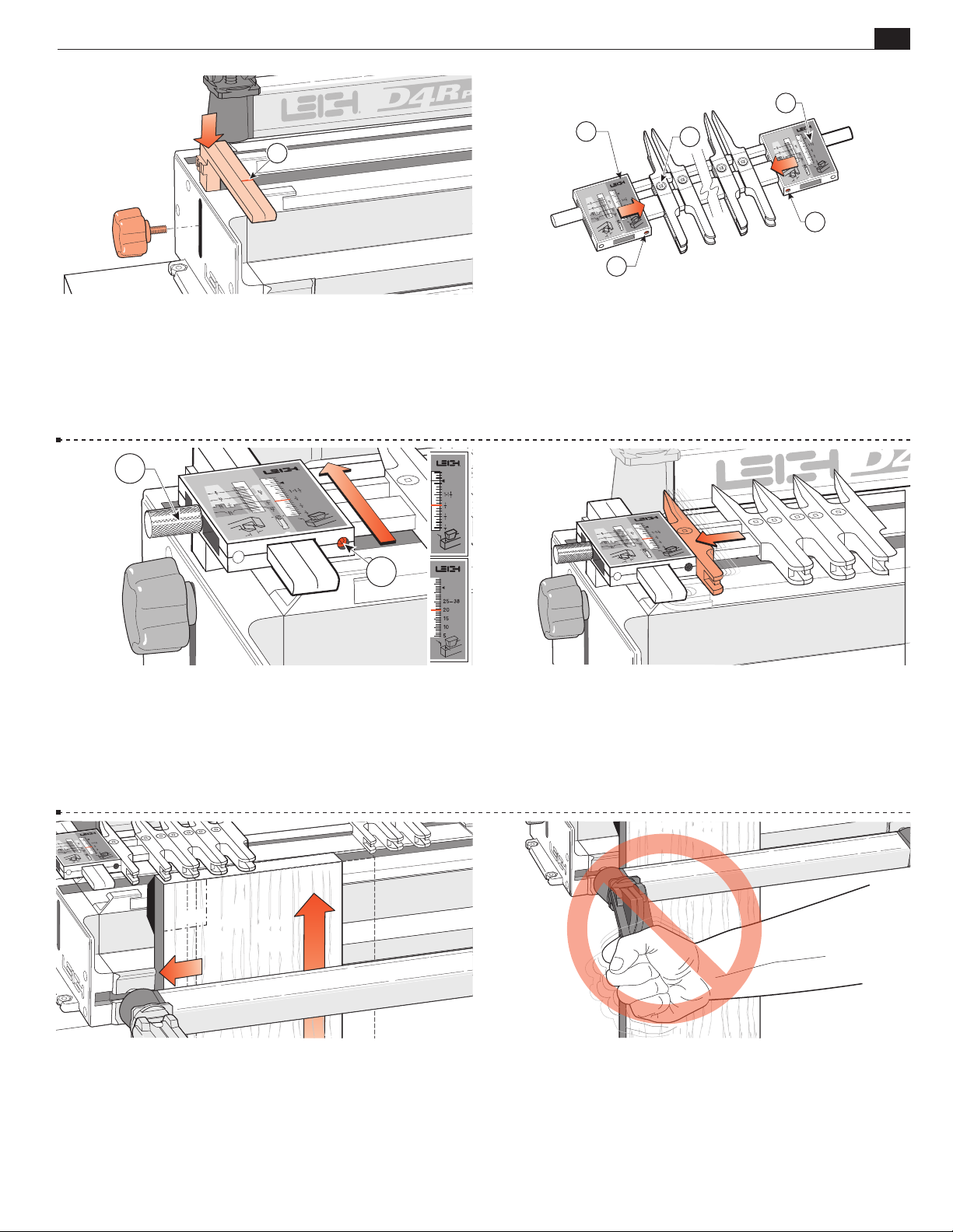
1-7 Insert the right and left support brackets. Attach the
knobs, raise to full height and tighten. Note: For clarity, the set
line is drawn in red. The actual lines are black.
1
2
2
3
1
3
1-8 Place the finger assembly on your bench with the guidefinger
screws on top and the pointed ends of the guidefingers away
from you. Fit the scales onto the finger assembly, placing the
HB TAILS scale to the right at both ends. Do not tighten
H
the scale set screws
yet. Note: The 1⁄4 " square half-blind pin bar
is supposed to be shorter than the finger bar. It is not inteneded
to fit in the scales at both ends.
1-9 Slide the complete finger assembly with loose scales onto
3
the support brackets. Set the bracket index line at
HB TAILS scale and tighten the thumb screws . Tighten
the
H
⁄4 "[20mm] on
the scale screws firmly with the hex key provided. If the scales
are removed from the finger bar for any reason, follow this
procedure to re-attach them.
1-11 You will operate the cam-action speed-clamps every time
you use the jig, so get used to the feel of the clamps first. Use
some square ended boards for practice. Make sure the end of the
board is touching the underside of the guidefingers. Then slide
the board over against the side stop.
1-10 Loosen the thumbscrews and make sure the finger assembly
slides on and off the support brackets smoothly, in both the tail
and pin modes. Move the outermost guidefinger at each end of the
finger assembly outward to touch the scales, and tighten. If fingers
do not slide easily, see note on page 7. This finger acts as an end
support for the router and is not generally used as a guide.
1-12 Do Not force the cam-action speed-clamp. It has great
leverage, and excessive force may damage the workpiece or the
jig.
Page 12
4
Chapter 1 D4 R Pro User Guide
JIG ASSEMBLY, MOUNTING, AND USING THE CLAMPS
1-13
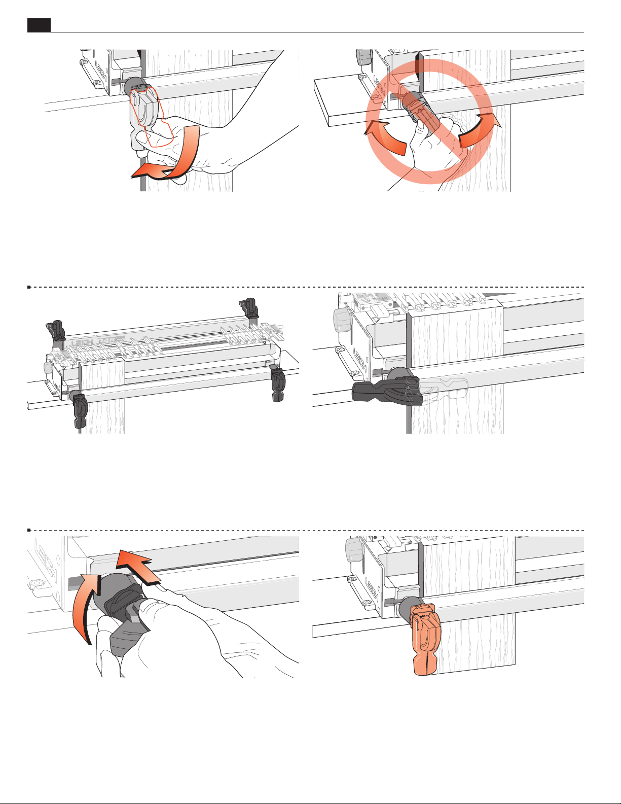
A smooth, firm action is enough to engage the clamp.
Rule of thumb: If you can’t throw the lever comfortably by pressing
the end of it with your thumb, reduce the tension. A few minutes
of trial and error will help you feel the right clamp tension. Firm
thumb pressure is about right.
1-15 When engaged, the front clamp levers should point down
and the rear clamp levers should point away from the operator.
1-14 Do Not use the lever as a torque arm. Adjust the clamp
tension only with the clamp disengaged.
1-16 If the lever is badly positioned at the correct clamping
pressure...
1-17 Release the clamp, remove the board and turn the step
washer a quarter turn (the step height inside the step washer is
one quarter of the thread pitch).
1-18 Then adjust the clamp until the clamp lever is in the right
position at the right pressure.
Page 13
JIG ASSEMBLY, MOUNTING, AND USING THE CLAMPS
1
2
3
1"[24mm]
Chapter 1D4 R Pro User Guide
5
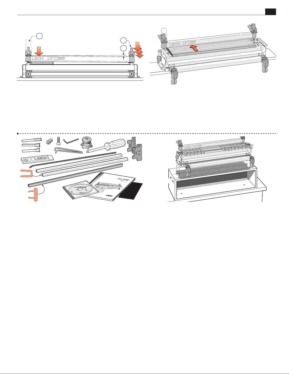
1-19 For all but the wider workpieces, you need only operate
the clamp on the workpiece end of the jig to release the board.
For narrower boards, the clamp at the free end should be just
1
tight enough to bow the clamp bar about
⁄8"[3mm] greatly
exaggerated in this view.
1-21 After you have assembled and mounted the jig, you will
have some items left over:
1 straight router bit Leigh No.140-8
1 dovetail router bit Leigh No.80-8
1 dovetail router bit Leigh No.120-8
1 collet reducer
1 Leigh wrench/gauge
(gauge: Ch.9)
1 accessory attachment screw (Ch.9)
1 hex key, allen wrench
1 Leigh e7 elliptical guidebush
1 pin wrench (eBush adjustment wrench)
1 Leigh guide finger adjustment screwdriver
2 spacers, one for single pass half-blind dovetails
(Ch.11), and
one for box joints (Ch.15)
2 lengths of bridge piece extrusion (Ch.10)
1 cross cut fence (Ch.16)
1 nylon stop rod (Ch.11)
1 instructional DVD, and this user guide.
Please keep all these items ready for use.
1 warranty card. Please register your warranty. You will auto-
matically be entered in Leigh’s Warranty Registration Contest.
1-20 Make up a spacer board. This board will be used to support
the finger assembly in all front-clamping vertical board modes.
The spac er board should be flat, straight and of even thickness.
We suggest 3⁄4 "x6"[20x150mm] by approximately 23" [580mm]
long. Note: the thickness of the spacer board has no relationship
to the thickness of the vertical board being routed.
1-22 To gain height for a more comfortable working position
or for routing longer boards, mount the jig to a box that can be
bolted securely to a bench.
See also fig. 17-15.
■
Page 14

6
Chapter 1 D4 R Pro User Guide
JIG ASSEMBLY, MOUNTING, AND USING THE CLAMPS
Page 15
11
1
D4R Pro - CHAPTER 2
Adjusting the Finger Assembly
THE FINGER ASSEMBLY IS THE HEART OF THE LEIGH JIG.
Spend a few minutes now to familiarize yourself with these simple adjustments.
NOTE: The first few times you use your jig, some fingers may "stick". This is normal. To "unstick", loosen the finger
screw approximately 3/4 of a turn, and with the screwdriver still in the screw, press down firmly (on the screwdriver).
This will loosen the finger locking wedge (you should feel a click). The finger will now move freely.
7
7
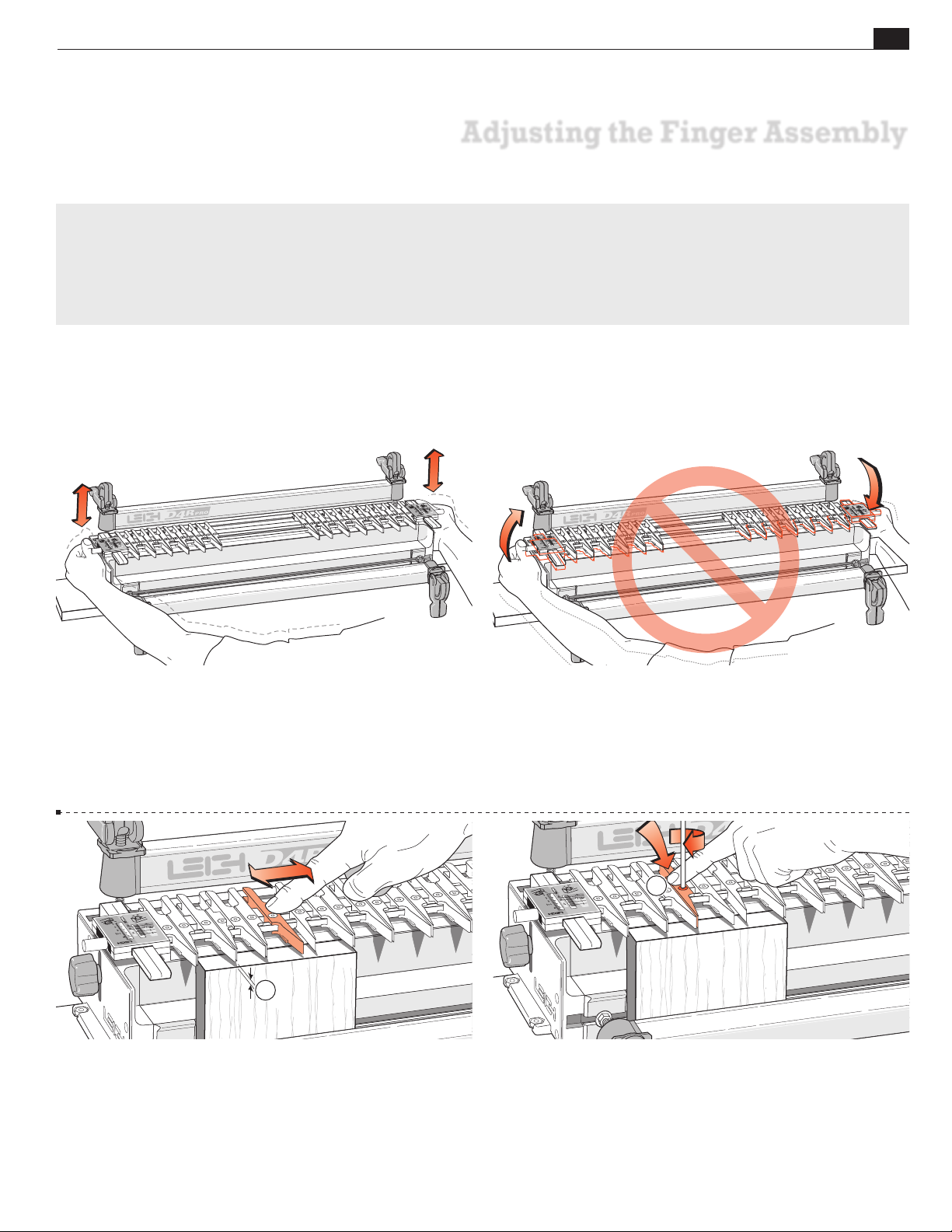
2-1 Practice adjusting the finger assembly height. Loosen the
support bracket knobs and hold them firmly. Raise and lower the
assembly evenly, keeping it level, and tighten the knobs to lock it
at various heights.
2-3 To practice adjusting the guide fingers, put a board in the
front clamp. Always raise the finger assembly slightly, approxi-
1
mately
⁄8"[2mm] above the spacer board and/or workpiece .
This is essential to allow the guide fingers to move freely on the
guide finger bar and ensures that the fingers will be level and
flush when locked up. Move the guide fingers by pushing on the
middle to slide them along the guide finger bar.
2-2 Do Not raise or lower one end of the finger assembly at a
time.
2-4 Loosen about half the guide fingers and practice unlocking,
moving, positioning and re-locking them. Always press down
lightly on the center of each guide finger
when tightening
the screws.
If after loosening a finger it “sticks” and doesn’t slide, see header note
above.
Page 16
8
Chapter 2 D4 R Pro User Guide
ADJUSTING THE FINGER ASSEMBLY
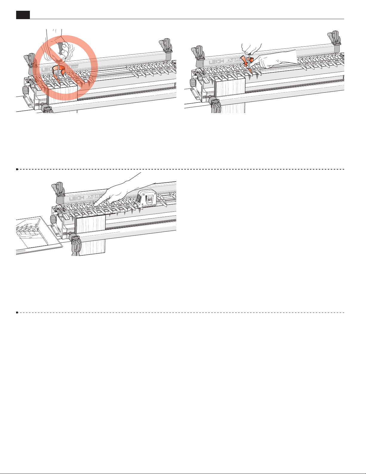
2-5 Do not over-tighten the guide finger locking screws. The
Leigh screwdriver provided will give ample torque for easy lock-up
without strain.
2-7 You can adjust the guide fingers by eye, or by measurement
to suit a set of plans.
Note: Always lower the finger assembly down onto the workpiece
before routing.
■
2-6 Always tighten unused guide fingers before routing, as router
vibration will cause loose screws and wedge nuts to fall out and
be lost.
Page 17
These images were copied from D4R Pro UG Fig’s 8-42 and 3-2
D4R Pro - CHAPTER 3
The Leigh e-Bush and
Optional Guidebushes
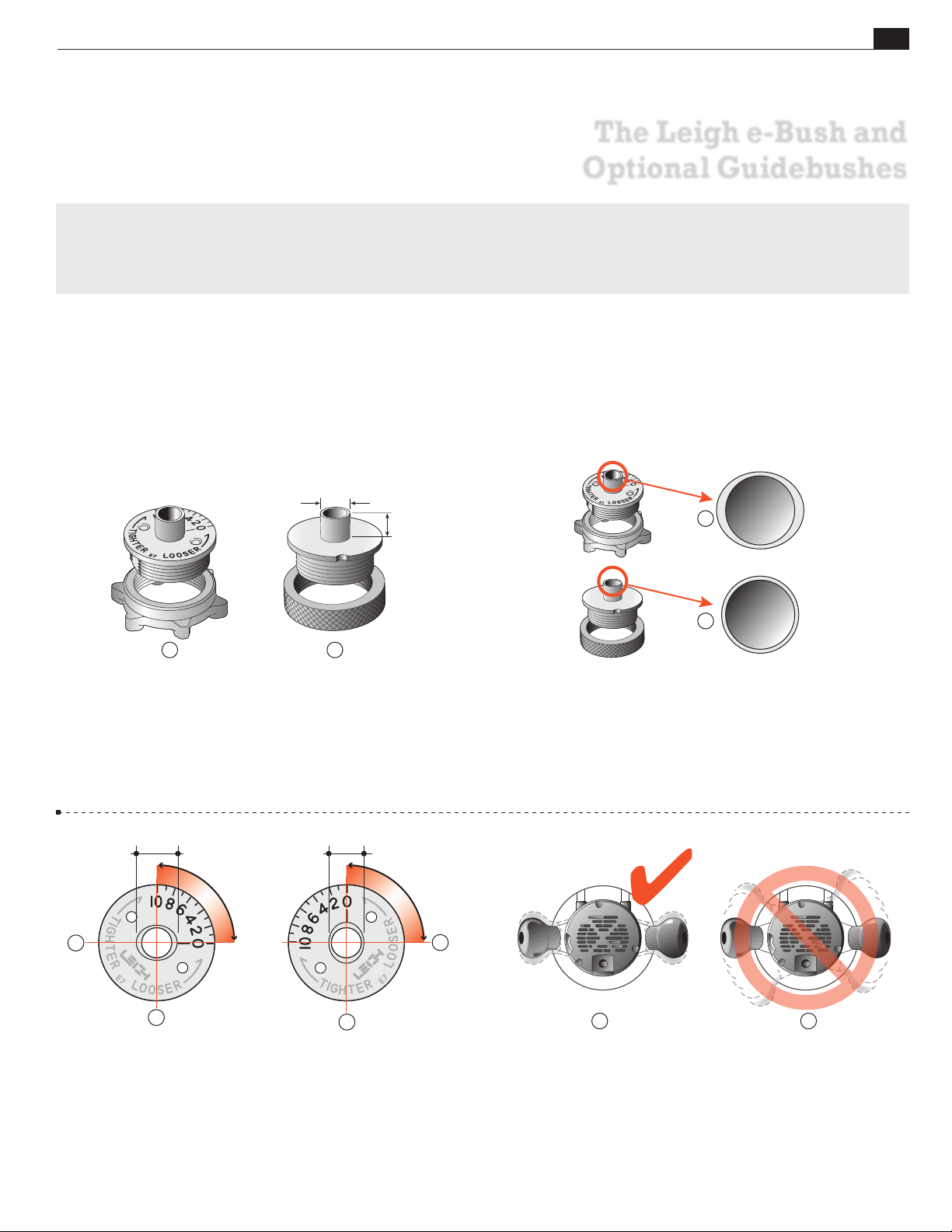
The guidebush is the vital link between router and jig. All joints created on the D4R Pro are routed with the unique
e7* elliptical guidebush, a Leigh innovation that provides precise joint fit adjustment for box joints and sliding dovetails.
If your router doesn’t accept the e7-Bush, you can use an alternative guidebush with some limitations.
*Supplied with the D4R Pro. U.S. Patent No. 8,256,475. UK Patent No. GB2443974. Patent Pending in Canada.
7
16
"
[~11,1mm]~
/
9
9
min.
[6,35mm]
1 2
3-1 The Leigh e7-Bush is used to rout through, half-blind, sin-
gle pass half-blind and sliding dovetails on the D4R Pro. The elliptical design provides precise joint fit adjustment for box joints and
7
sliding dovetails. A round ~
1
rel length
/4"[6,35mm]) can be used to rout through, half-blind,
/16"[11,1mm] guidebush (min. bar-
and sliding dovetails on the D4R Pro, but the e7-Bush is superior.
~7⁄16"[11,1mm] ~7⁄16"[11,1mm] less .020"[,5mm]
1
1
4
"
/
2
1
3-2 The Leigh e7-Bush that comes with your D4R Pro is a
unique template guidebush that is adjustable in size. Unlike regular
circular template guidebushes , the e7-Bush is slightly elliptical
in cross section . This simple innovation effectively changes the
guidebush “active diameter size” when it’s rotated, and provides
benefits not possible with a standard round guidebush.
2
2
1
3-3 The e7-Bush (~7/16") fits the router base or a guide bush
adaptor in the base (see Appendix I). The ellipse/oval shape has a
major axis ~7/16"[11,1mm], and minor axis ~7/16"[11,1mm] less
.020"[,5mm]. Turning the e-Bush 90 degrees in the router base
changes the active diameter by .020"[,5mm] providing minute
adjustment and recordable settings for perfectly fitting box joints.
1 2
3-4 Here’s how it works. In normal use on a dovetail jig, the
operator does not rotate the router more than a few degrees either
way . In fact, because of potential bit-to-bush eccentricity problems it is advisable to minimize router rotation on jigs .
Page 18
10
12 o’clock position
1
Chapter 3 D4 R Pro User Guide
12 o’clock position
1
THE LEIGH e-BUSH AND OPTIONAL GUIDEBUSHES
3-5 Establish the orientation in which you normally hold and
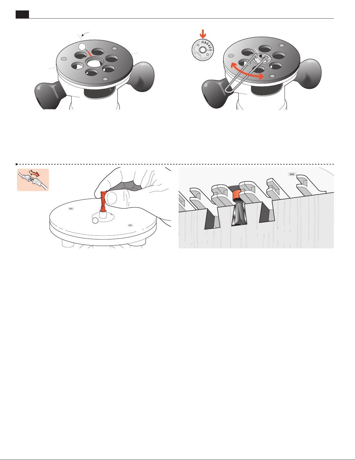
operate the router on the jig. Now, up-end the router in the same
orientation. Make a small scratch line or permanent ink mark
on the router base or e-Bush adaptor at the 12 o’clock position.
Learn about e-Bush adaptors on page 69.
1
3-7 The bit goes through the e7-Bush and fits in the router
collet or chuck.
3-6 Fit the
e7-Bush to the router and align No.10 to the scratch
mark. This setting is used for all through and variably spaced halfblind dovetails on the D4R Pro. Settings for single pass half-blinds,
box joints and sliding dovetails are described in applicable chapters.
Be sure to retighten the e-Bush nut after each adjustment is made
with the included pin wrench.
3-8 The projecting part of the guidebush runs along the side
edge of the guide finger. The rotating bit cuts the wood only, and
touches neither the guidebush nor the guide surface.
■
Page 19
D4R Pro CHAPTER 4
Basic Jig Functions and Scale Modes
Here are the very basics for understanding the different D4R Pro dovetail modes and settings.
THE FOUR SCALE MODES
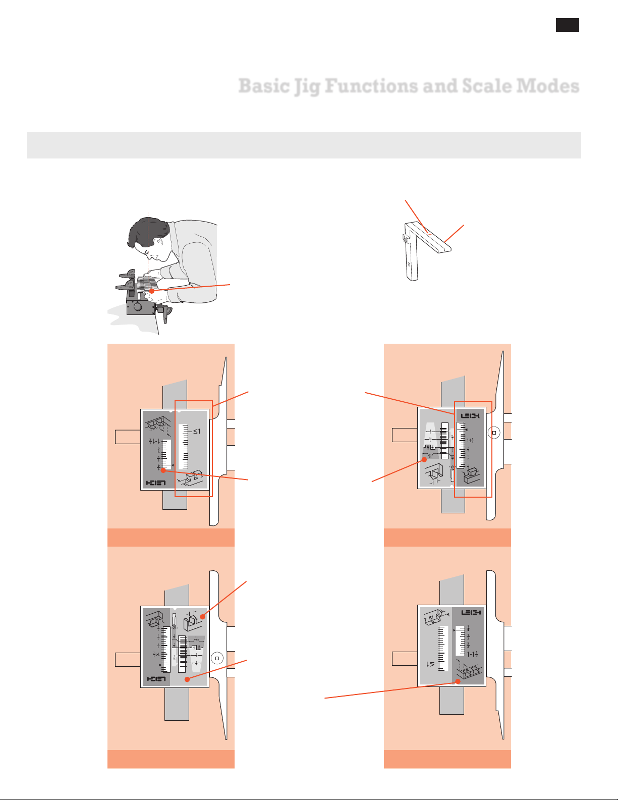
The Finger Assembly attaches to the support brackets in four
different modes to match the type of joint you are cutting.
Always read scales from
directly overhead to avoid
parallax problems.
This index line is used when setting the finger assembly
scales. The line is illustrated in red for clarity, but is black
on the jig.
11
All D4R Pro jigs are shipped
with “short” support brackets.
1. TD TAILS
Note: Inch scales are shown
here. Millimeter scales have
identical layout.
The active scale is always
on the right of each scale
assembly.
The inactive scale is always on
the left of each scale assembly
and is upside-down.
3. HB TAILS
Each scale has its own mode
icon (a drawing of the joint
part made in that mode).
2. TD PINS
Scales are color coded.
Silver background for
Through Dovetails.
Green background for HalfBlind Dovetails.
The specific settings for each
scale are fully described in
the appropriate chapters.
4. HB PINS
Page 20
12
Chapter 4 D4 R Pro User Guide
BASIC JIG FUNCTIONS AND SCALE MODES
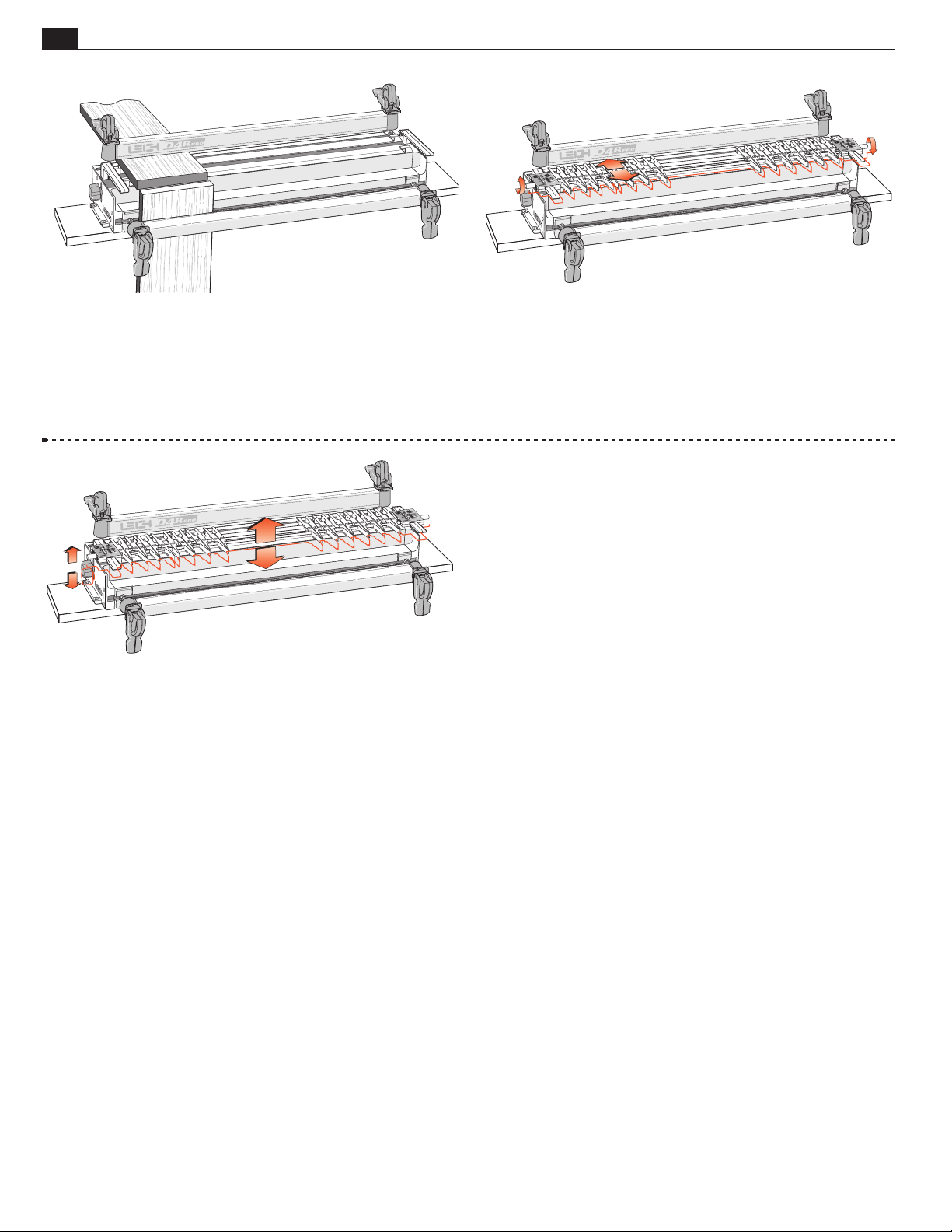
4-1 The two clamp bars hold workpieces horizontally or vertically. The side stops align the boards in the correct position each
time.
4-3 The finger assembly is raised or lowered using the support
brackets to suit different thicknesses of horizontal boards.
■
4-2 The guidefinger assembly slides on to the support brackets
above the workpiece. The finger assembly is adjusted in or out
using calibrated scales on each end to suit different thicknesses of
vertical boards.
Page 21
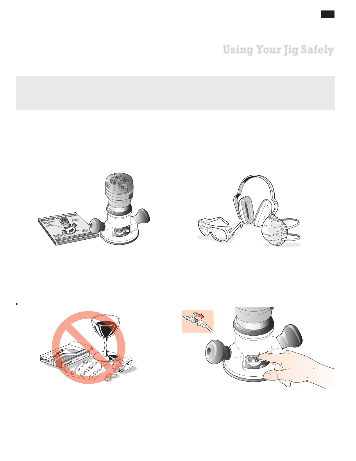
Safety is not optional.
Read and follow the recommendations in this chapter.
13
D4R Pro - CHAPTER 5
Using Your Jig Safely
5-1 Read the owner’s manual that came with your router. It is
essential to understand the router manufacturer’s instructions
completely. Always operate variable speed routers at the fastest
possible speed.
5-3
Never drink alcohol or take medications that may cause
drowsiness when you will be operating a router.
5-2 Always wear approved safety glasses.
Always wear hearing protection.
Protect yourself from harmful dust with a face mask.
For complete dust and waste collection, add a Leigh VRS (Vacuum
& Router Support) to your jig. See page vi.
5-4 Always disconnect the power source from the router when
fitting bits or guidebushes, or making adjustments.
Before connecting the router to the power source, make sure the
bit and collet revolve freely in all the areas you plan to rout, and
the bit does not touch the guidebush or jig.
Page 22
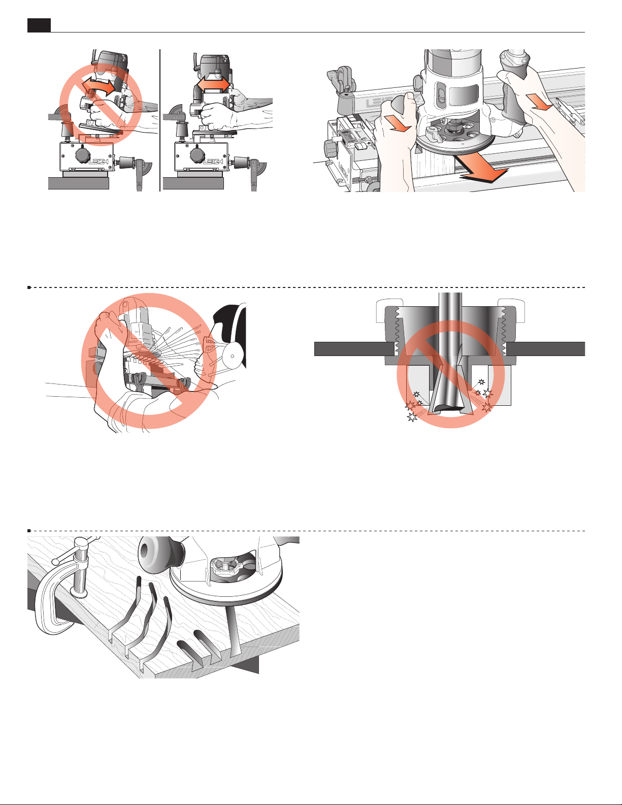
14
Chapter 5 D4 R Pro User Guide
USING YOUR JIG SAFELY
5-5 Do not tilt the router on the jig.
Keep the router flat on the jig assembly.
Note: The optional Leigh VRS attachment prevents router tilting.
See page vi.
5-6 If you insist on removing the router from the jig while it
is still revolving, always pull it straight off the jig horizontally,
and do not raise or lower the router until it is completely clear
of the jig. With the Leigh VRS fitted to your jig you can simply
park your router to one side.
5-7 Do not rout at face level. 5-8 Never release the router plunge mechanism when using
dovetail bits. Check if your plunge router has a stop nut to prevent
this from happening accidentally.
5-9 If you have never used your router before, be sure to follow
the router manufacturer’s instructions for its use. Make plenty
of simple open-face practice cuts without a guidebush before
you try to use the router on the Leigh jig. You must, of course,
always use a guidebush when routing on the Leigh Jig.
■
Page 23
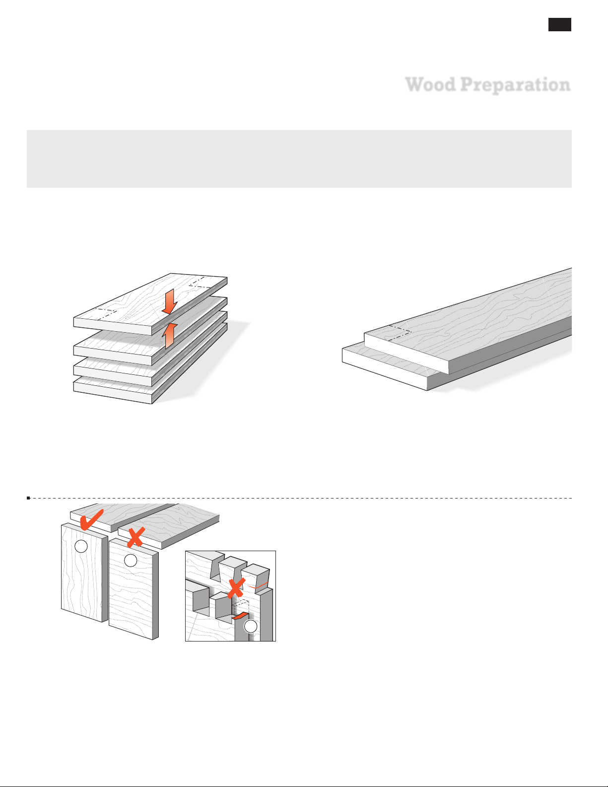
"Garbage In - Garbage Out"...
This adage of the computer age stands equally true for dovetail jigs.
90°
15
D4R Pro - CHAPTER 6
Wood Preparation
90°
6-1 It is vital for accurately aligned joints that stock used on the
Leigh jig must be prepared straight, flat, of even thickness and equal
widths, with square ends and edges. Note that plywood is generally
unsuitable for routing because of tearout problems.
1
2
90°
6-2 You will want to test the jig, so prepare some 3⁄4" x
1
⁄2"[20x140mm] boards. Cut them to length as you need them
5
for the jig tests you want to perform. Use them for practice with
the jig’s various joint modes so you can see how the different
modes work. Remember, though, that two boards of different
thicknesses can be joined just as easily.
3
6-3
Dovetail joints are intended for joining end-grain
to end-grain . Attempting to cut dovetails in side-
grain does not work because:
A. The wood will tear out badly when routing.
B. Even if you could rout them, the pins and tails would easily
break off across the short grain , either during or soon after
the assembly when the boards start expanding or contracting
at different rates.
■
Page 24

16
Chapter 6 D4 R Pro User Guide
WOOD PREPARATION
Page 25
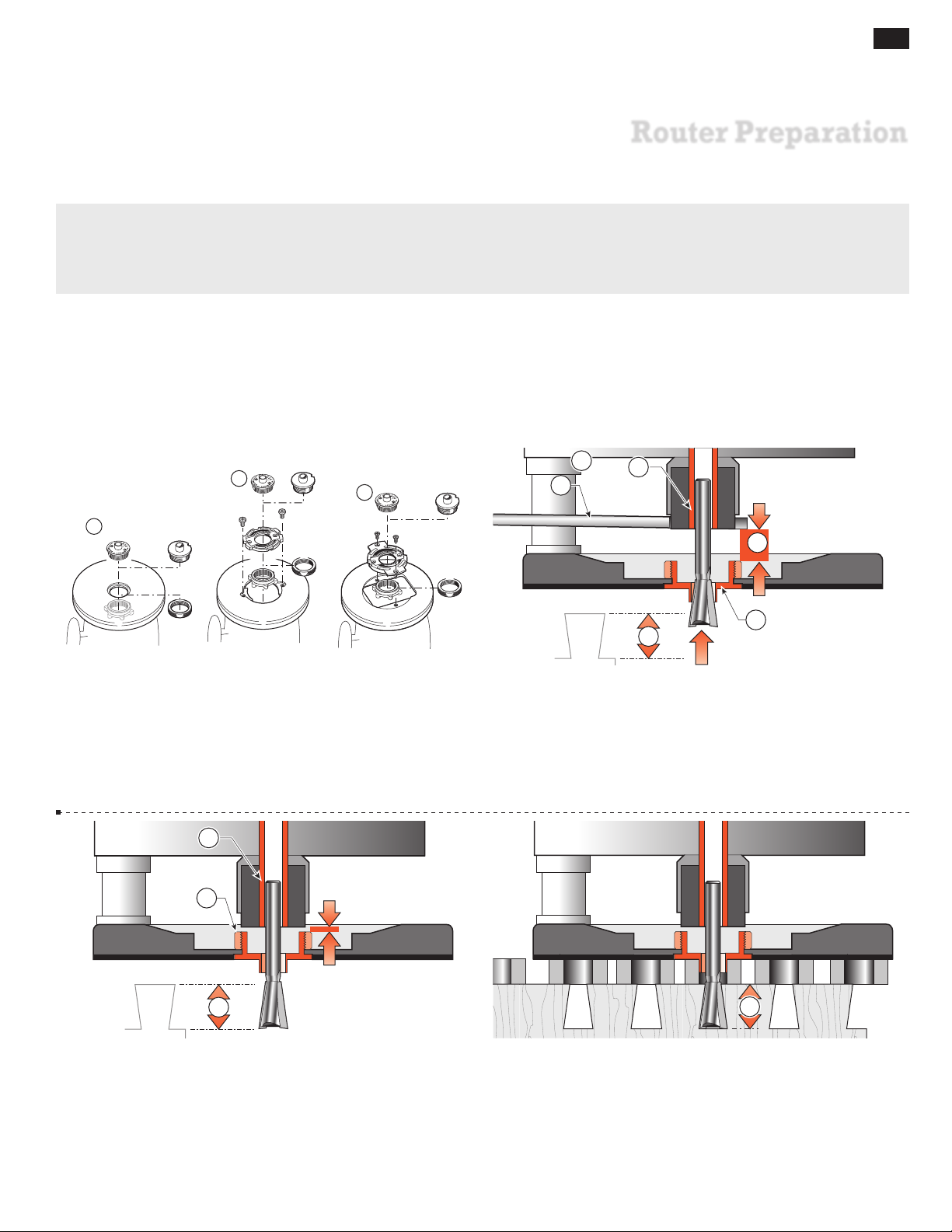
17
D4R Pro - CHAPTER 7
Router Preparation
1
1
1
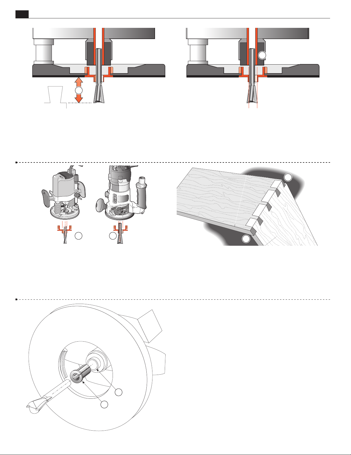
7-1 Fit the e7-Bush . One is included with your D4R Pro.
7
If the e-Bush is incompatible with your router, any ~
1
guidebush (min. barrel length
/4" See page 70) will work for all
/16"[11,1mm]
but box joints on the D4R Pro.
2
5
1
3
2
4
5
6
7-2 When fitting a bit to the router , fit the shank as far into
the collet
as possible. Always rout with the collet as close to the
guidebush as possible. Usually you can’t securely grip the collet nut
with a wrench
bit so that the remaining travel
if the collet is at its optimum low position. Fit the
between collet and guidebush
will let the bit reach the required depth of cut .
6
7-3 Tighten the collet securely and lower the collet to adjust
the depth of cut , but make sure the collet does not contact the
guidebush . Some smaller collets can go down into the inside
of the guide bush. Take advantage of this.
1
7-4 Depth of Cut: The depth of cut always refers to the actual
of the cut into the wood beneath the guidefingers .
depth
Page 26
18
Chapter 7 D4 R Pro User Guide
2
ROUTER PREPARATION
1
7-5 Depth of cut is not the distance the bit projects from the
router base. This is bit projection
. This guide generally refers
to depth of cut. Bit projection is always .450"[11,5mm] more
than depth of cut.
2 2
7-7
Concentricity problems can only arise if two routers are used for
through dovetails, (one for pins; one for tails). Routers with different bit
to guidebush offsets (misalignment shown highly exaggerated)…
7-6
Ideally, the router collet (and bit) should be concentric (centered) to the guidebush as in figure 7-5. Regrettably, this is often not
the case; the bit can be off center (eccentric to) the guidebush . The
illustration shows the problem highly exaggerated. The good news:
bit to bush alignment doesn’t affect joint fit or flushness; both are
“adjusted out” in normal jig setup.
3
3
7-8
…will cause pin to tailboard
misalignment (again, shown
highly exaggerated).
Fortunately, some newer routers have sub-bases that can adjust
for concentricity. If you don’t have this type, it might pay to stick
to a single router for through dovetails.
7-9 Shank Selection/Collet Reducer
All Leigh Dovetail jigs are shipped with superior strength 8mm
1
shank dovetail bits and a
simply slides into the 1⁄2" collet of your router (do not remove
⁄2" to 8mm collet reducer. The reducer
the collet nut) and the 8mm shank bit is inserted into the collet
reducer. The collet is tightened as normal. The collet reducer is
1
not required with
5
4
⁄2" shank bits.
■
Page 27
19
D4R Pro - CHAPTER 8
Through Dovetails
In these instructions for the Leigh D4R Pro Dovetail Jig, we have recommended certain bits and board sizes because
they are easy to work with. When you have routed some practice joints and gained confidence in your ability to
get the results you want, free to use the guidebush and adaptor selection charts in Appendix I, pages 69-70, and
bit options in Appendix II, pages 71-77, to plan whatever dovetail routing you need for your projects.
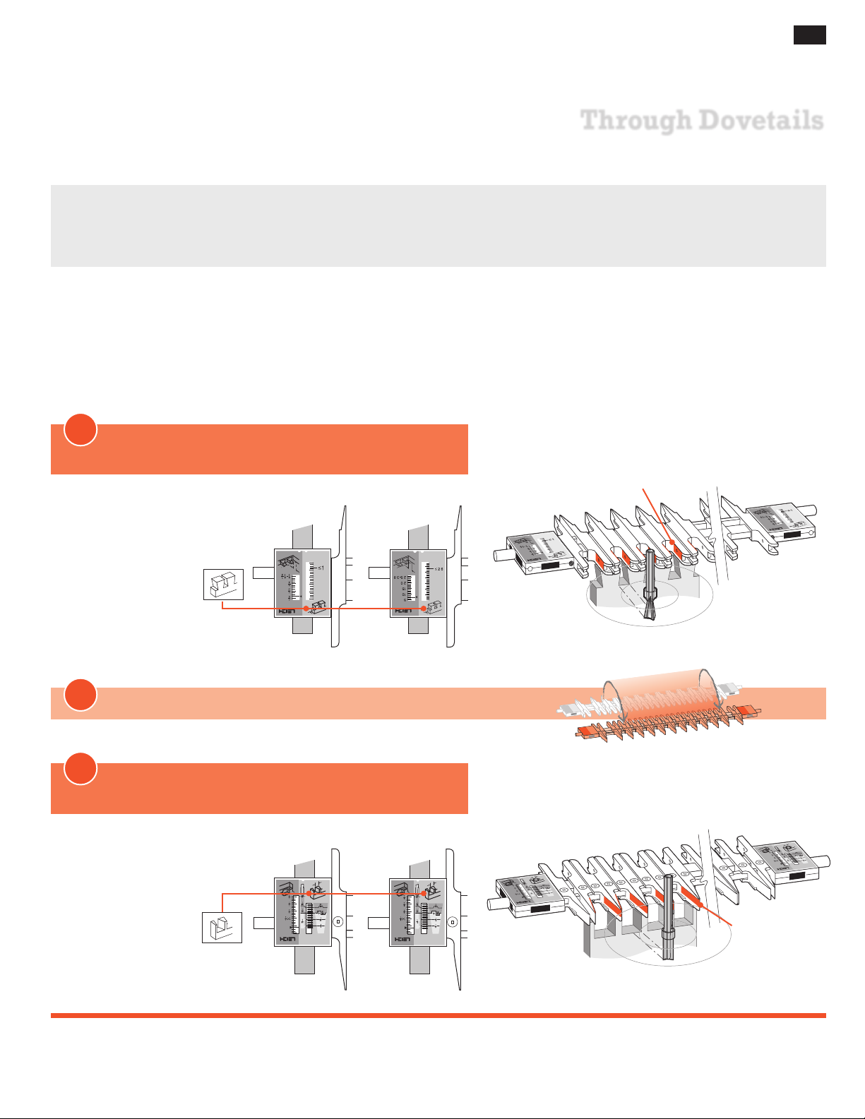
Concept of Jig Operation – THROUGH DOVETAILS
Start with the Finger Assembly in the D TD TAIL mode and follow these steps on your jig. Grasping the simple basic concept of
operation will now greatly assist you in understanding the instructions. Note that the active guide surface (against which the guidebush
runs) is indicated in red in these illustrations.
1
Start in
Through Dovetail Tails (TD TAILS) mode
MODE ICONS
Illustrations in this user
guide include the correct
mode icon for the current instruction. The
icons are also used in
the instruction text.
Inches Millimeters
Active
Guide Surfaces
2
ROTATE the finger assembly toward you 180°
3
Now the Finger Assembly is in
Through Dovetail Pins (TD PINS) mode
Inches Millimeters
TD TAILS
TD PINS
Active
Guide Surfaces
Page 28
20
Chapter 8 D4R Pro User Guide
2
5
4
6
3
1
THROUGH DOVETAILS
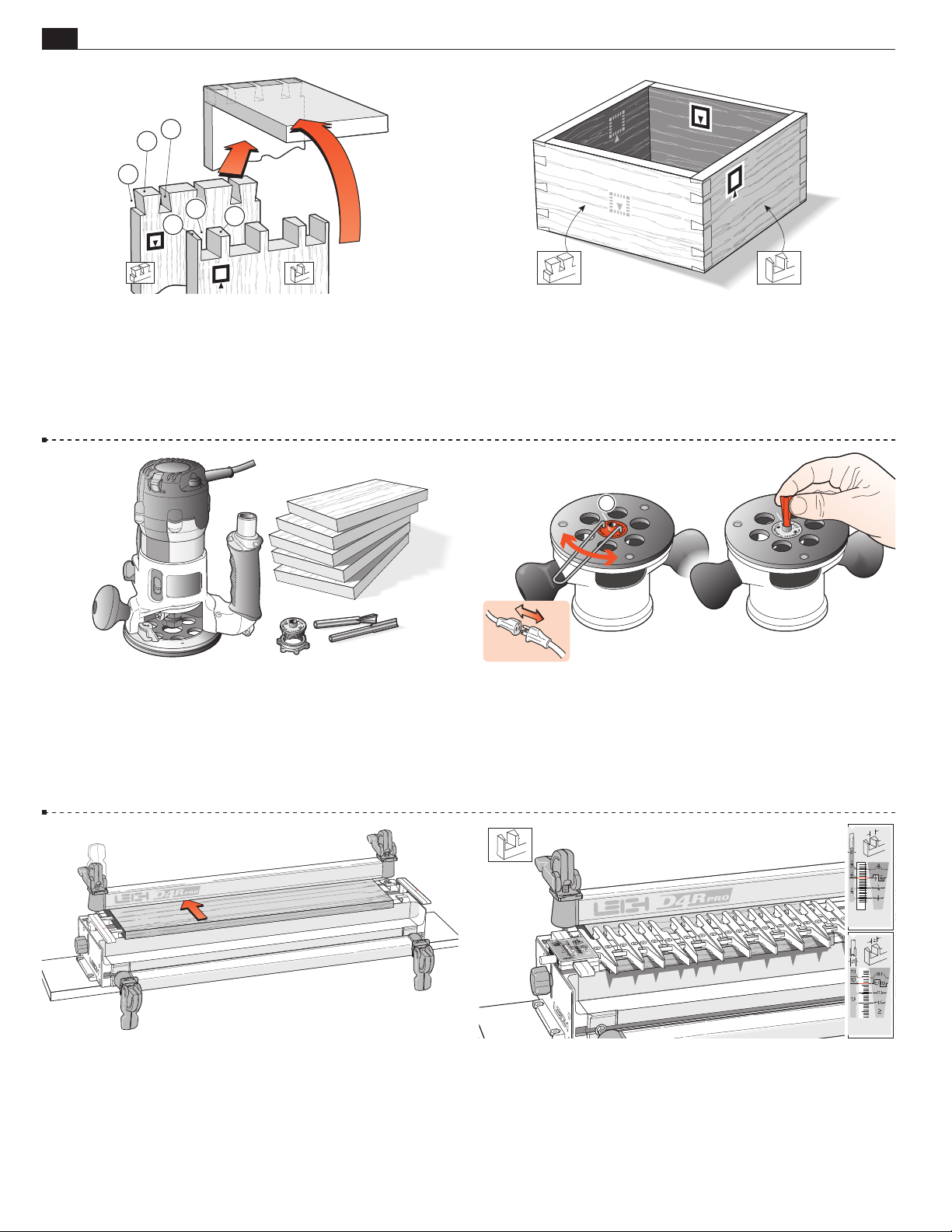
8-1 Through Dovetail Terminology:
Pins
Pin sockets
Half-pins
Half-pin sockets
Tails
Tail sockets
The pins fit in the pin sockets. Joints should almost always end
each side with half-pins.
8-3 Make five identical boards 3⁄4"x 5-1⁄2"[20x140mm] about
8"[200mm] long. Mark the inside faces of the two tailboards and outside
faces of the three pinboards (you may not need one of the pinboards).
7
Use: Leigh e7 or
- No. 80-8
- No.140-8
⁄16"[11,1mm] O.D. guidebush with:
1
⁄2"[12,7mm]x 8° dovetail bit and
5
⁄16"[7,9mm] straight bit.
8-2 Let’s look at how to make a simple square box. When you
assemble the finished pieces with the faces properly oriented, any
one of the pin ends will fit any one of the tail ends. In fact, the
box can be put together in six different ways …each of the four
corners will fit two ways!
1
8-4 Fit the e7-Bush or 7⁄16" securely to the router and set it to
the No. 10 index mark
. Then fit the supplied 80-8 dovetail bit
to the router. Note: The e7 guidebush is not used to adjust joint
tightness with through dovetails.
8-5 Clamp the spacer board in the rear clamp.
8-6 Place the finger assembly on the support brackets in the d
TD PINS mode, flat on the spacer board, and with the scale set
1
on the
⁄2"[12,7mm] setting for now. Don’t worry about the scale’s
specific meaning now. Each scale’s use will be fully explained in
the appropriate section.
Page 29
THROUGH DOVETAILS
Chapter 8D4R Pro User Guide
1
21
8-7 Clamp a tail board against the left front side stop, top edge
touching flush under the guidefingers, inside face
away from the
i
jig body. Although you will cut tails first, adjust the guidefinger
layout in
TD PINS mode. The adjustment screws are on top
d
in this mode, and it's easier to visualize the final joint pattern.
8-9 This joint layout is only a suggestion for this trial. It has a
typical, traditional symmetrical layout of pins, with half-pins at
each edge. The Leigh jig, however, allows for an infinite variety
of joint designs, and boards of different thicknesses can also be
joined to each other as shown in this illustration. Before attempting joints of asymmetrical layout, please see chapter 14.
8-8 Loosen the support bracket knobs and raise the finger assem-
1
bly about
⁄8"[3mm] above the boards and retighten the knobs.
This will allow easy and accurate guidefinger adjustment.
8-10 Ignoring the extreme outer guidefinger next to the scale (it
just supports the router), loosen the next eight guidefingers and slide
them over the workpiece. NOTE: The first few times you use your
jig, some fingers may "stick". This is normal. To "unstick", loosen the
finger screw about 3/4 turn. Press down firmly on the screwdriver (in
the screw) to loosen the finger locking wedge (you should feel a click).
2
1
8-11 Lock the left-most half-pin guidefinger about 1⁄8"[3mm]
in from the left edge of the board. Always apply light downward
pressure to each guidefinger as the finger screws are tightened .
This will ensure the fingers are flat and level on the bar.
1
8-12 Leave three pairs of guidefingers over the board and lock
1
the right-most half-pin guidefinger about
⁄8"[3mm] in from
the right edge of the board. Judge this distance by eye: it need not
be exact. The sockets and pins will align automatically.
Page 30
22
Chapter 8 D4R Pro User Guide
THROUGH DOVETAILS
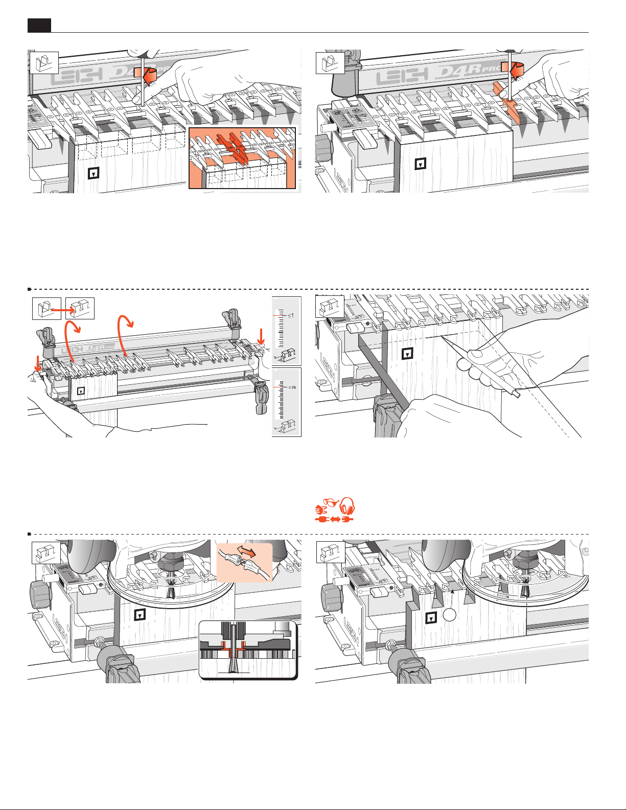
8-13 Space and lock the three remaining pairs as shown. Again,
judge it by eye. If it looks right on the jig, the finished joint will
look right. Note: Here we have shown pins of equal width, but
with tails of increasing width. However, by opening up a pair of
guides, the pin (and pin socket) can be widened for decorative or
structural reasons as shown in the drawing inset.
8-15 Rotate the finger assembly to the D TD TAILS mode, and
set it to the ≤1"[≤26mm] position on the scale. Lower the finger
assembly onto the spacer board. All TD tails are routed at this
≤1"[≤26mm] setting. (The ≤1" setting allows the dovetail bit
to pass completely through all tail boards.)
8-14 Tighten any other loose guidefingers.
8-16 Place the end of a pin board horizontally flush under the
guidefingers and mark a thin pencil line partly across the tail
board.
REMEMBER SAFETY!
8-17 Place the router on the finger assembly and adjust the router
until the dovetail bit tip is level with the center of the pencil line.
Note: This means the pin socket will be half a thin pencil line deeper
than the thickness of the pin board, leaving minimal cleanup after
assembly. Check to make sure the bit rotates freely.
1
8-18 Before routing the tails, read “Hints and Tips 17-10". Plug in
the router and rout out the half-pin and pin sockets. Use only light
side pressure on the guide fingers. Take care not to rout unwanted
sockets where there are gaps between the pairs of fingers . Rout
only between the rounded guidefinger tips. See Hints and Tips
17-20.
Page 31
THROUGH DOVETAILS
2
4
1
3
Chapter 8D4R Pro User Guide
23
1
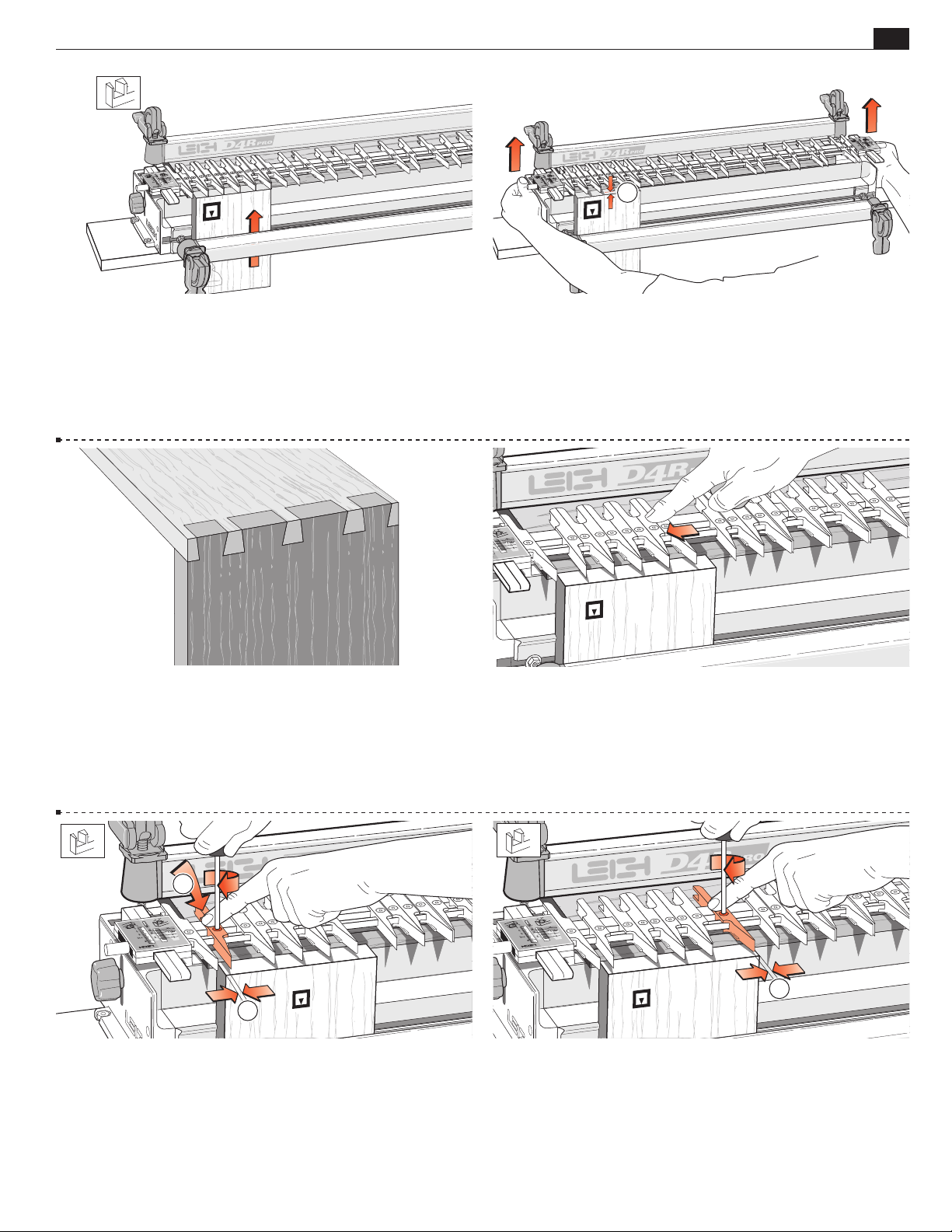
1
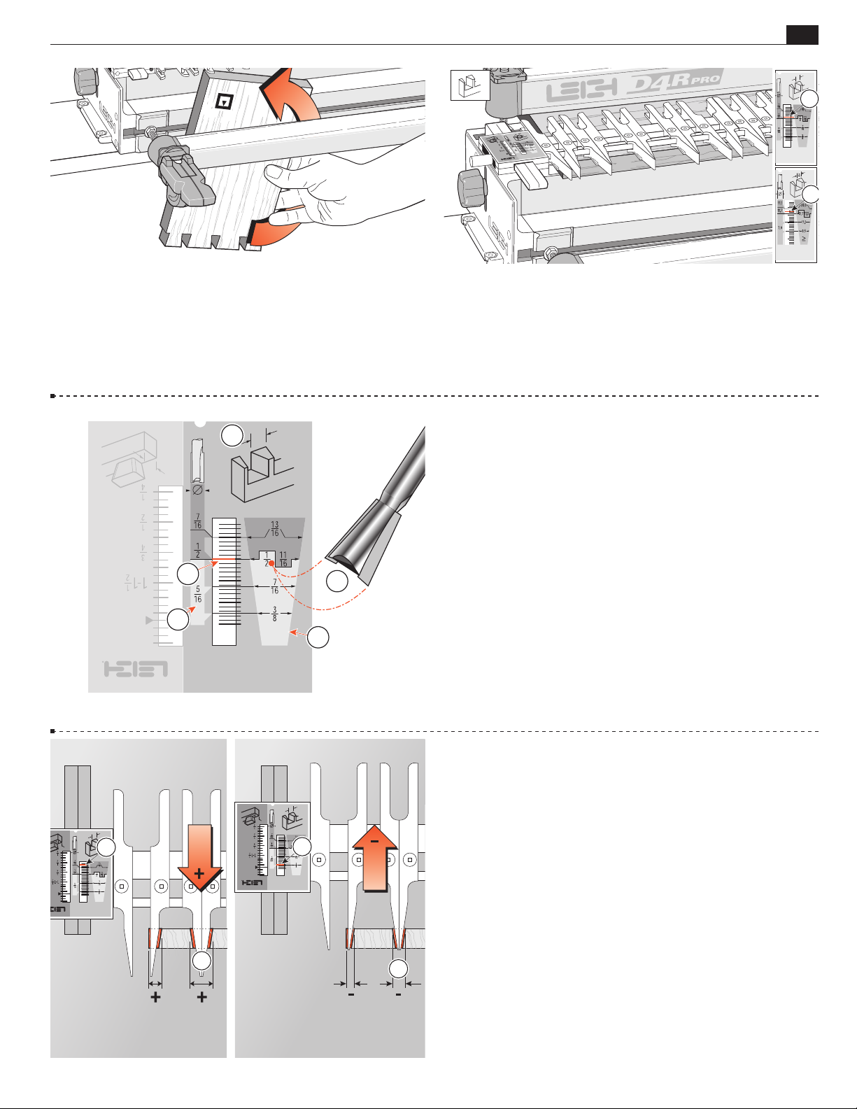
8-19 Before removing the routed board from the jig, check by
eye and touch to make sure no parts have been missed. Release
the clamp and reverse the tail board in the jig, keeping the same
inside face
away from the jig body.
i
Rout the other end of this tail board and both ends of the second tail
board in the same fashion, then unclamp and put them aside.
3
5
4
2
1
8-20 Rotate the finger assembly to the d TD PINS mode and
1
set it one scale increment more than the
⁄2"[12,7mm] mark .
Do not change the guidefinger layout.
8-21 How the TD PIN Scales Work
Dimensions inside the pin shaped panel correspond with the
diameter of the dovetail bit chosen to rout the tails
1
example the
1
⁄2"[12,7mm] setting on the scale. This also becomes the width
the
⁄2"[12,7mm] diameter of the #80-8 dovetail bit matches
. In this
of the pin .
Dimensions in the central panel indicate which straight bit diam-
5
eter is required with the selected dovetail bit, i.e.
1
straight bit with the
⁄2"[12,7mm], 7⁄16"[11,1mm] and 3⁄8"[9,5mm]
⁄16"[7,9mm]
diameter dovetail bits.
The increment lines in the scale window are referenced to the
index lines on the support brackets when making fit adjustments.
Once the desired fit is achieved, settings can be recorded for precise
setup next time.
8-22 Finished Joint Tightness
The fit of the finished joint is determined in the dTD PINS
mode. Moving the finger assembly outward increases the width
of the pins , giving a tighter fit. Moving the finger assembly backwards allows more wood to be routed, making the pins smaller ,
and the joint looser. A one increment movement changes joint fit
by 0.005"[0,125mm]. A one quarter increment movement changes
fit by a tiny 0.00125"[0,03mm]. Most importantly, when that
fine fit is achieved, it allows recordable and repeatable settings for
future joints using the same router and bits (see page 28).
Why can’t there be specific, preset scale settings for
each bit combination?
Cumulative tolerances in routers, bits, guidebushes and the dovetail
jig, make it impossible to give exact jig settings for a precision glue
joint. A fine fitting joint can only be attained by trial and error test
cuts, and takes only minutes for each bit combination. Dimension
lines on the TD PIN scale provides the starting point for testing.
Page 32
24
Chapter 8 D4R Pro User Guide
1
1 2
2
3
4
THROUGH DOVETAILS
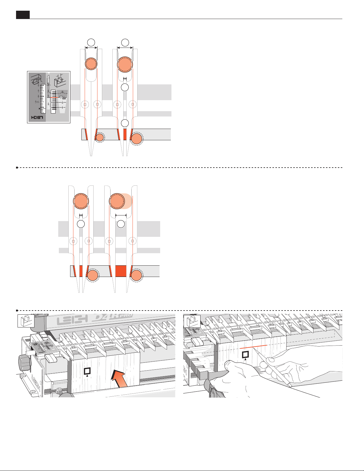
8-23
Why are the 1⁄2" and 11⁄16"[12,7&17,5mm] pin widths
on the same scale line?
1
⁄2
" through dovetails are routed using a 7⁄16
11
⁄16" through dovetails are routed with a 5⁄8" guidebush .
3
That's a
⁄16" difference in size between the two bits …and between
" guidebush
the two guidebushes.
5
⁄8" diameter guidebush for 11⁄16" joints requires that the guide
The
3
fingers be opened up by
This automatically makes the pins
⁄16" .
3
⁄16" wider but on the same
scale setting.
8-24 Do the guide fingers have to be opened up precisely
3
⁄16"[4,75mm] for larger combinations?
No, just so long as they are opened up by at least 3⁄16"(4,75mm)
to allow the larger guidebush to enter the tail guides. Anything more
than this minimum is fine ; both the pin and matching pin socket
widths will be automatically increased by exactly the same amount,
whatever the spacing. Varying the pin width does not affect the joint
fit or the scale setting. In fact, the pin width can be varied with all
bit combinations, not just the larger bits
8-25 Clamp a test pin board against the left hand side stop,
outside face
away from the jig, with the top end flush under
o
the guides.
8-26 Place the side edge of one of the finished tail boards horizontally
flush under the guidefingers and mark a thin pencil line part way
across the pin board.
Page 33
THROUGH DOVETAILS
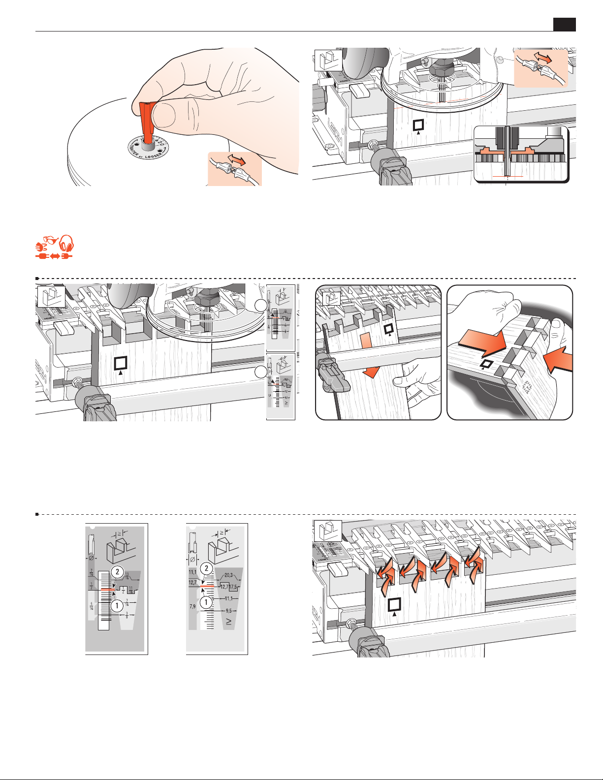
90
o
Chapter 8D4R Pro User Guide
25
8-27 Unplug the router and remove the dovetail bit. Mount the
No. 140-8 straight bit to the router. If you are using two routers,
see concentricity concerns, Figures 7-6 thru 7-8.
REMEMBER SAFETY!
1
1
8-29 Check that the scales are set one increment above the
1
⁄2"[12,7mm] mark . Rout out the waste between the pins.
Check to make sure no parts have been missed. See 17-1 to 17-5,
"Hints and Tips" on how to minimize tearout.
Use only light side pressure on the guide fingers.
8-28 Place the router on the finger assembly and adjust the router
until the tip of the bit is level with the center of the pencil line.
Check to make sure the bit rotates freely.
8-30 Remove the test pin board from the jig and test it for fit in
one of the tail boards. Make sure the outside faces
face outward
o
on both pieces. The joint will probably be too tight. A firm push
fit is perfect, perhaps a tap with the heel of your hand. But having
to use a mallet means the joint is too tight to take glue.
8-31 If it is much too tight, move the finger assembly in (away
from you) by one division on the scale. If it is only a little tight,
adjust the scale by only half a division. If it is too loose, go to
8-33.
8-32 Replace the same pin board back in the jig, carefully aligned
against the same side stop. Rout off the sides of the pins and test
it again for fit.
Page 34
26
Chapter 8 D4R Pro User Guide
1
2
1
3
o
90
THROUGH DOVETAILS
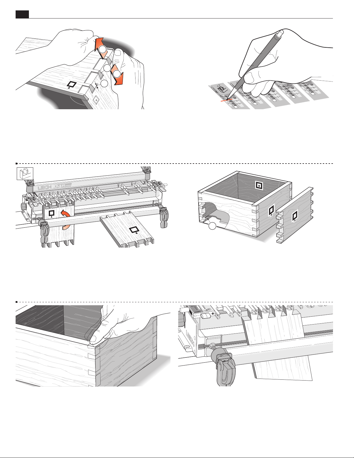
8-33 Test and repeat as required to achieve the desired fit.
Note: If you overdo it and make a loose joint, do this test. Pull the tail board
“away” from the pins so that the angled sides of the pins and tails jam
together . The gap between the bottom of the pins and the pin sockets ,
is the amount to move the finger assembly out, (toward you). Reset the finger
assembly and test again on the other end of this (fifth) board.
8-35 Rout all four ends of the pin boards, keeping the outside
face
outwards. (With luck you may not have used the fifth
o
board.)
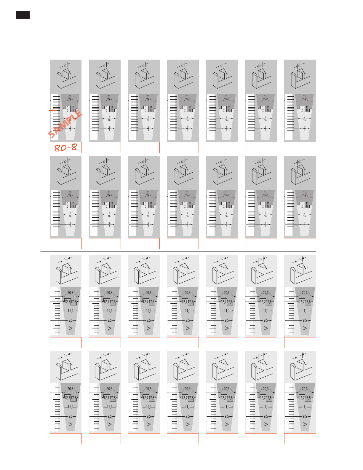
8-34 Once the correct fit is achieved, mark the final d TD
PINS scale setting on one of the scale prints (see page 28) for
future reference. Very slight variations to the scale setting may be
necessary with different wood species or hardness.
B
A
1
A
B
A
A
8-36 Assemble the box, making sure the tail boards face the
proper way, i.e. tail boards inside face in i; pin boards outside
face out o. Provided you haven't already routed out the drawer
bottom grooves , it doesn't matter which edge of any of the
boards are at the top or bottom, the box will still fit together i.e.
pin board “A” can be up either way.
8-37 The box should be square and in plane. If it is not in plane
(i.e., the side edges of each board are not in line), then either the
ends of the boards are not square, the board widths are not exactly
equal, or there is a concentricity problem (see 7-6 to 7-8).
8-38 To form angled dovetails, refer to the Technical Bulletin
“How to Rout Angled Through Dovetails on your Leigh Jig". You
can download this bulletin from the support page of our website:
http://www.leighjigs.com/support.php.
■
Page 35
THROUGH DOVETAILS
QUICK REFERENCE REMINDERS
Chapter 8D4R Pro User Guide
27
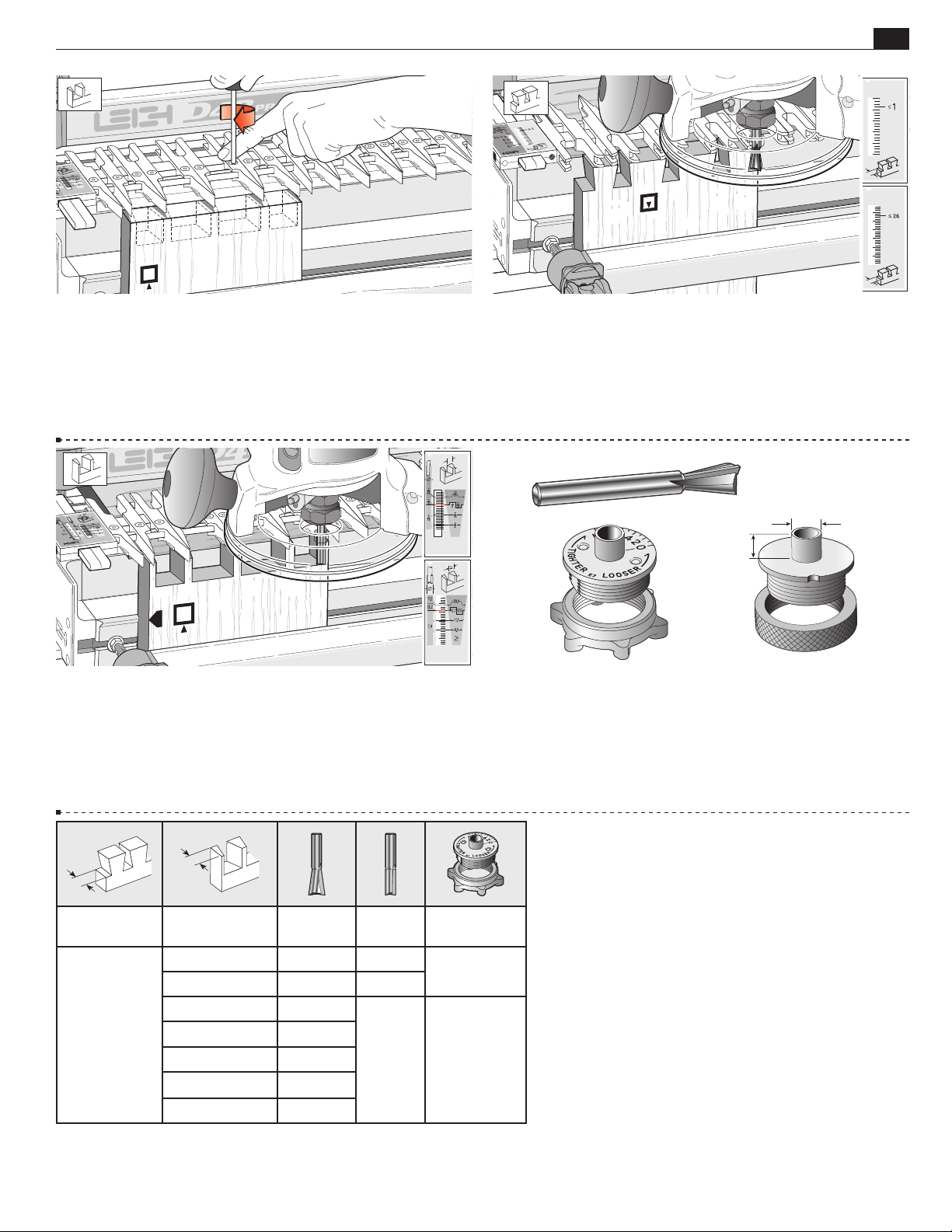
8-39 Through dovetails are laid out in the d TD PINS mode
with the finger assembly slightly raised above the spacer board.
The outside face
of the TD pins is away from the jig body.
o
8-41 Clamp TD pin boards vertically in the jig. This is the only
one of the four main modes that puts the outside face
board away from the jig body. The finger assembly is in
of the
o
d
TD
PINS mode, with the scale set to a recorded setting (see detailed
fit instructions 8-21 to 8-34). TD pins are cut with a straight bit;
the only time a straight bit is used in dovetailing.
8-40 TD tail boards are clamped vertically in the jig. The inside
of the TD tails is away from the jig body. The finger assem-
face
i
bly is in the
TD TAILS mode, set on the single ≤1"[≤26mm]
D
setting. There is only one setting in this mode.
7
16
"
[11,1mm]~
/
1
4
"
/
[6,35mm]
8-42 Through dovetail tails are always routed with an 8° dovetail
bit to match the 8° guide finger. All through dovetail routing on the
D4R Pro is done with the Leigh e7-Bush, or any 7⁄16" [11,1mm]
1
diameter bush (min. barrel length
more on routers and guidebushings. The e10-Bush or a
O.D. guidebush is used for
⁄4"[6,35mm]). See page 70 for
1
⁄2" shank TD bits.
5
⁄8"[15,9]
Thickness of
Tail Board
up to 1" [26]
Numbers in brackets are millimeters
Thickness of
Pin Board
1
1" - 1
/4" [26-32] No.100 No.150
5
/8" - 1" [16-26] No.90 No.160
1
/2" - 13/16" [12-20] No.80-8
3
/8" - 5/8" [10-16] No.75-8
1
/4" - 1/2" [6-13] No.70-8
3
up to
/8" [10] No.60-8
1
up to
/4" [6] No.50-8
Dovetail
Bit
Straight
Bit
No.140-8
Guidebush
Diameter
Leigh e10
5
/8" [15,9]
or
Leigh e7
7
/16" [11,1]
or ~
8-43 Here is a quick reference selection chart for
through dovetail bits and guidebushes. Please study
the bit and guidebush selection appendixes for a full
explanation.
■
Page 36
28
SAMPLE
Chapter 8 D4R Pro User Guide
PROJECT SETTINGS
INCHESMETRIC
THROUGH DOVETAILS
Page 37
D4R Pro - CHAPTER 9
"[3mm]
Large and Small Through Dovetails
The following procedures considerably expand the D4R Pro jig’s versatility. However, before attempting them,
thoroughly master the techniques of Through Dovetails in Chapter 8.
29
9-1 LARGE THROUGH DOVETAILS
The procedures for using bits 90 and 160 or 100 and 150 are
5
identical to the previous figures, except that a
⁄8"[15,9mm] OD
guidebush, or Leigh e10 e-Bush is used, and each guidefinger
3
must be at least
3
⁄16"[5mm] thick) to make sure there is enough separation. Note:
(
Because the
pin centers using these bit combinations is 1
⁄16"[5mm] apart. Use the Leigh wrench gauge
5
⁄8"[15,9mm] guidebush is used, the closest possible
3
⁄8"[35mm], instead
of 1"[25,4mm].
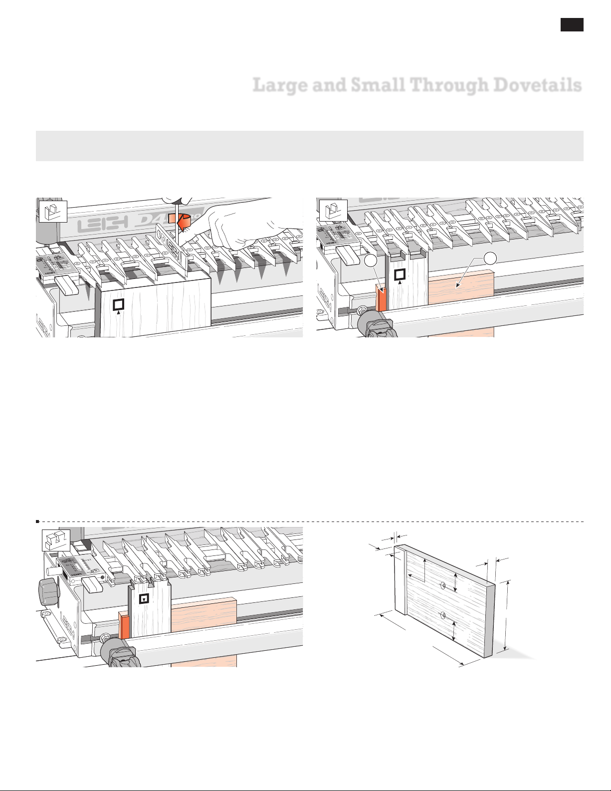
2
1
9-2 SMALL THROUGH DOVETAILS
Bits 50-8 and 60-8 allow you to create tiny through dovetails in
3
material
bonus: the Leigh jig was not originally designed for it. The
⁄8"[10mm] or less in thickness. This procedure is an extra
TD
d
PINS scale does not go down far enough, so you have to space the
boards away from the jig face with a shop-made block
with its own side stop
(see 9-4). Use the e7 or a 7⁄16"[11,1mm]
fitted
O.D. guidebush for these small joints.
1
8
/
~
3
~
/
4
"[20mm]
90
o
1
1
/
2
"[40mm]
1
"[13mm]
2
/
9-3 Use the same block with side stop when cutting the tails to
ensure correct alignment of the pin and tail boards.
"[140mm]
1
2
/
~5
6"[150mm]+
1
1
/
2
"[40mm]
9-4 Make the block with its side stop out of 1⁄2"[13mm] stock
1
as shown. Bore two
⁄4"[6mm] holes, countersunk for a flat head
screw (part no. 287) to allow the blocks to be used at either end
of the jig.
Page 38
30
SAMPLE
Chapter 9 D4 R Pro User Guide
LARGE AND SMALL THROUGH DOVETAILS
9-5 Remove one front cam clamp, lower the clamp bar and
attach the block to the jig face using the screw (No. 287) into the
entrapped square nut. Replace the clamp bar and cam clamp.
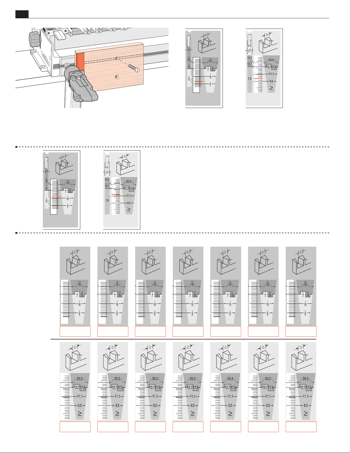
PROJECT SETTINGS
9-6 For boards up to 1⁄4"[6mm] thick use dovetail bit 50-8 and
7
pin bit 140-8 with the e7 or a
⁄16"[11,1mm] guidebush. To cut pins
matching the sockets made with bit 50-8, begin with the setting shown
here. Cut test pins in scrap stock and test for fit. Adjust as necessary.
9-7 For boards up to 3⁄8"[9,5mm] thick use dovetail bit 60-8 and
7
pin bit 140-8 with the e7 or a
⁄16"[11,1mm] guidebush. To cut pins
matching the sockets made with bit 60-8, begin with the setting shown
here. Cut test pieces in some scrap stock and test for fit, then adjust as
necessary. Record the actual settings for bits 50-8 and 60-8 on these
scale reproductions below.
5
Note: You may also rout joints in boards
⁄16" to 3⁄8"[8,0 to 9,5mm]
with bits No. 70-8 and 140-8 without the use of the shop-made
block.
INCHESMETRIC
Page 39
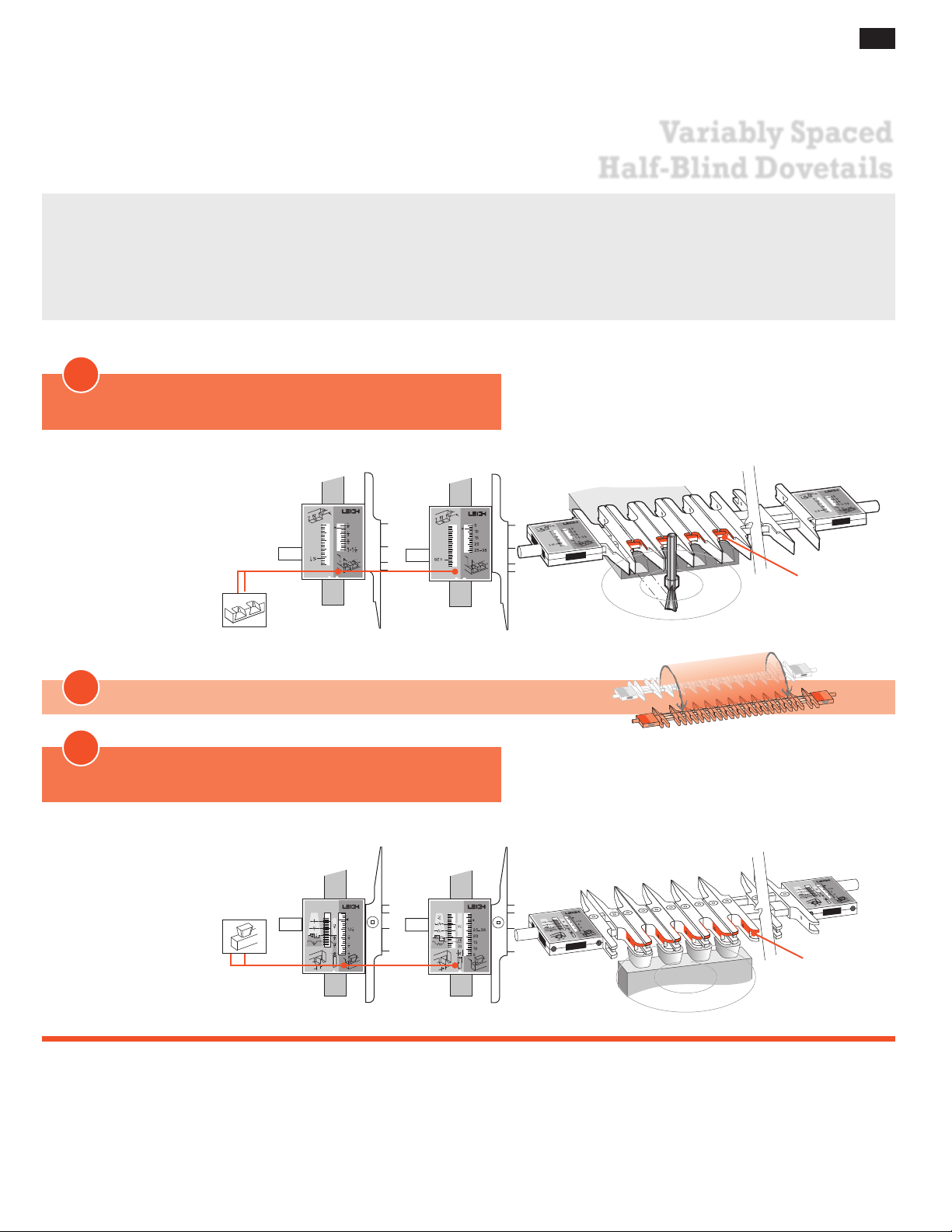
D4R Pro - CHAPTER 10
Variably Spaced
Half-Blind Dovetails
IMPORTANT! The most commonly misunderstood aspect of routing half-blind dovetails is how the dovetail bit’s
The following procedures considerably expand the D4R Pro jig's versatility. However, before attempting them,
depth of cut is used to adjust the joint fit, and how the angle of the bit affects that depth of cut. Review this chapter
thoroughly master the techniques of Through Dovetails in Chapter 8.
for a clear understanding of this concept.
7
Note: The Leigh e7-Bush or any ~
any one of the bits listed on the next page may be used for half-blind dovetails. See Appendix II, Half-Blind Bit
Selection, Page 75, for a full description on how to select an appropriate bit.
1
Start in
Half-Blind Dovetail Pins (HB PINS) mode
/16" [11,1mm] guidebush with a min. barrel length of 1/4" (see page 70), and
31
MODE ICONS
Illustrations in this manual include the correct
mode icon for the current instruction. The
icons are also used in
the instruction text.
2
ROTATE the finger assembly toward you 180°
3
Now the Finger Assembly is in
Inches Millimeters
Half-Blind Dovetail Tails (HB TAILS) mode
Inches Millimeters
Active
Guide Surfaces
HB PINS
HB TAILS
Active
Guide Surfaces
Page 40
32
4
2
5
1
6
3
Depth of Cut
Depth of Cut
" [3,2mm] Min.
Board Thickness
" [3,2mm] Min.
Board Thickness
Chapter 10 D4 R Pro User Guide
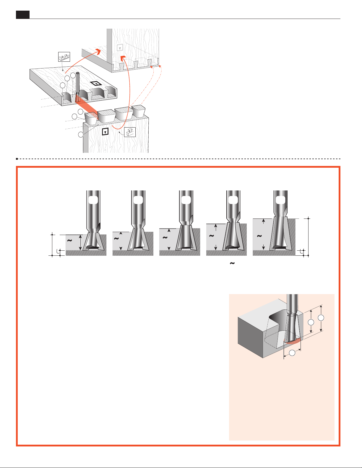
10-2 Cutting Depth for Variably Spaced Half-Blind Dovetails
VARIABLY SPACED HALF-BLIND DOVETAILS
10-1 Half-Blind Dovetail Terminology:
Pins
Pin sockets
Half-pins
h
Half-pin sockets
Tails
H
Tail Sockets
The pins fit in the pin sockets. Joints should almost always end each
side with half-pins.
Bit selection is critical. You need to
select a specific dovetail bit for your
half-blind dovetail project, depending
on the pinboard (drawer front) thickness you are using.
• Choose one of the five 1⁄2" [12,7mm]
• Depth of cut must be as specified
• Raising the bit above its specified
128-8
DEPTH
OF CUT
3
/8"
8
/
[9mm]
1
Note: Add at least
18
˚
[11mm]
1
⁄8"[3,2mm] to the depth of cut for board thickness.
Important! Read This About HB Depth of Cut
diameter dovetail bits shown above.
Check bit selection in Appendix II.
for each of the five bits illustrated
above. Note: Leigh bits 101-8, 112-8
and 128-8 are optional.
cutting depth will result in loose
joints and may damage the jig, bit
and/or guidebush. A lower setting
7
/16"
120-8
14
[13mm]
˚
112-8
1
/2"
12
˚
will result in tighter joints that may
not fit together.
• Small Depth of Cut adjustments
will change joint fit tightness. See
10-3 to 10-5 for why.
• Half-blind PINS and TAILS are
routed with the same dovetail bit
and must be at the same Depth of
Cut.
• All half-blind dovetail bits work
with the Leigh e7-Bush supplied
with your Leigh jig or standard
7
⁄16"[11,1mm] outside diameter
guidebush.
5
/8"
[16mm]
101-8
DEPTH
OF CUT
[19mm]
10
˚
Symbol for “approximately”
80-8
3
/4"
8
/
1
8
˚
2
3
PINBOARD THICKNESS determines
the maximum depth of cut you can
use. Select a bit with a specified cutting
depth that is at least 1⁄8" less than the
pinboard thickness.
A dovetail bit will produce only one spe-
cific cutting depth.
Only 1⁄2" [12,7mm] cutting diameter bits
can be used for half-blind dovetails.
1
Page 41
VARIABLY SPACED HALF-BLIND DOVETAILS
Chapter 10D4R Pro User Guide
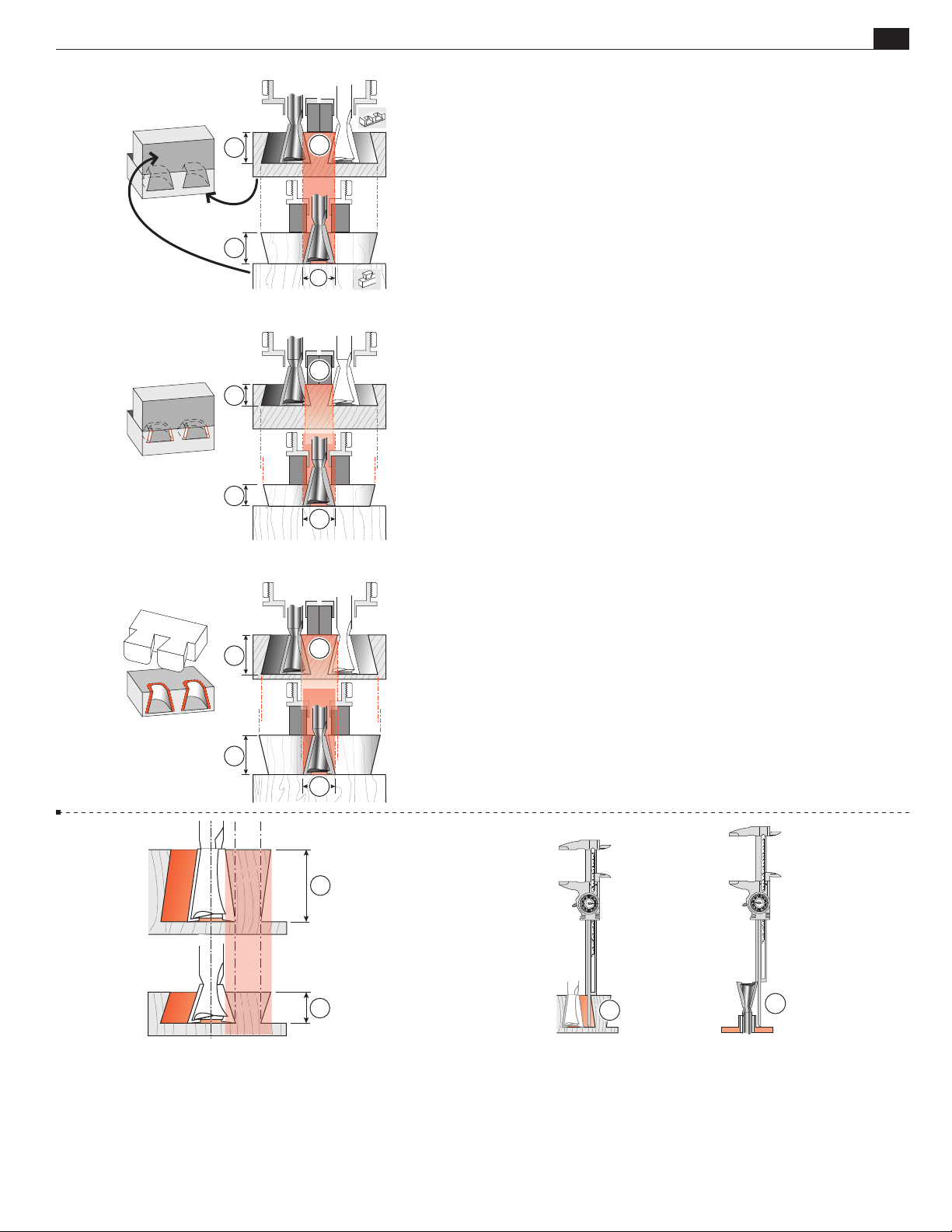
33
PIN
1
3
10-3 Joint Fit and Depth of Cut
Here’s why the depth of cut changes the fit in half-blind dovetails. Increasing or decreasing the depth of cut does not affect the
pin socket width , but does affect the width of the pin that
goes into the socket .
1
2
3
1
10-4 Note that decreasing the bit depth makes the pin nar-
rower while the pin socket stays the same width, producing a
loose fit.
Decreasing the bit depth (i.e. raise the bit into the router) produces a looser fit.
1
2
1
1
8˚
18˚
3
2
1
2
10-6 Bit Angle and Depth of Cut. Half-blind pins and tails
are routed with the same dovetail bit, the same guidebush, and
the same depth of cut. A different depth of cut requires a different angled bit. Leigh offers five different angled dovetail bits for
a range of cut depths. A lesser angle, say 8˚, for a deeper cut ; a
greater angle, say 18˚, for a shallower cut .
Increasing the bit depth makes the pin larger while
10-5
the pin socket stays the same width, producing too tight a fit.
Increasing the bit depth (i.e. lower the bit) produces a tighter
fit.
Bit
Depth
1
of Cut
2
Projection
10-7 Cumulative plus/minus tolerances in routers, bits and
guidebushes, make it impossible to state exact bit depth for firsttime precision fit. All dovetail jigs require trial and error tests to
attain fine fitting joints. The good news; we give a starting depth
for each bit. Test and measure the successful ‘Best fit’ depth of
cut or bit projection . Record for future first-time fits.
Page 42
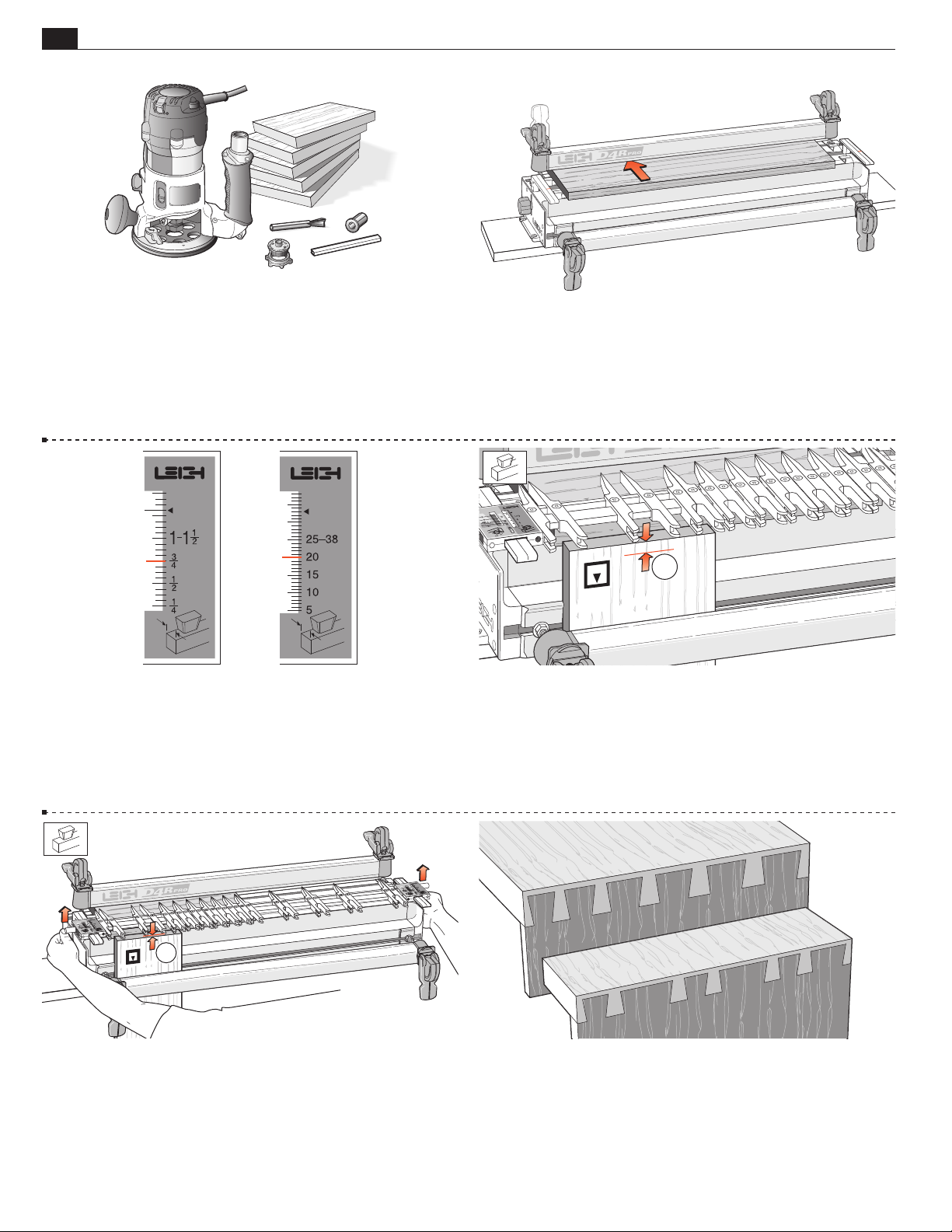
34
Chapter 10 D4 R Pro User Guide
VARIABLY SPACED HALF-BLIND DOVETAILS
10-8 Routing a Test Joint Use the Leigh e7-Bush, and No.120 -
1
⁄2"[12,7mm] 14° dovetail bit. Select several pieces of 3⁄4"x
8,
1
⁄2"[20 x 140mm] x about 8"[200mm], and the plastic bridge
5
1
extrusion. Note: Half-blind pin boards must be minimum
⁄2"(13mm)
thick to clamp. For thinner boards see fig.10-21.
10-10 Mount the finger assembly on the support brackets in
HB TAILS mode, flat on the spacer board, scales set on the
the
H
thickness of the tail board (
The
The scale increments above 1-1
HB TAILS scale is always set at the tail board thickness.
H
3
⁄4 "[20mm] in this instance).
1
⁄2"[25- 38mm] are for use on
sliding dovetails (see Chapter 16).
10-9 Clamp the spacer board in the rear clamp.
1
10 -11 Measure and mark a line on the inside face of the tail
board to the working depth of the bit to be used as per 10-2
of this chapter. Clamp this test tail board in the left front clamp,
against the side stop with the top edge flush under the guidefingers,
and the inside face
of the drawer side away from the jig.
i
1
10 -12 Unlock and raise the finger assembly support brackets
1
slightly so that the finger assembly is about
⁄8"[2mm] above
the boards. This will allow easy movement of the guidefingers.
10 -13 While typical traditional layouts have symmetrical pins and
spacing with half-pins at each edge, the Leigh jig allows infinitely
variable joint designs. Different thickness boards can be easily
joined together. Pins can be various sizes and randomly spaced to
suit just about any design you create. Before attempting joints of
asymmetrical design, see Chapter 14.
Page 43
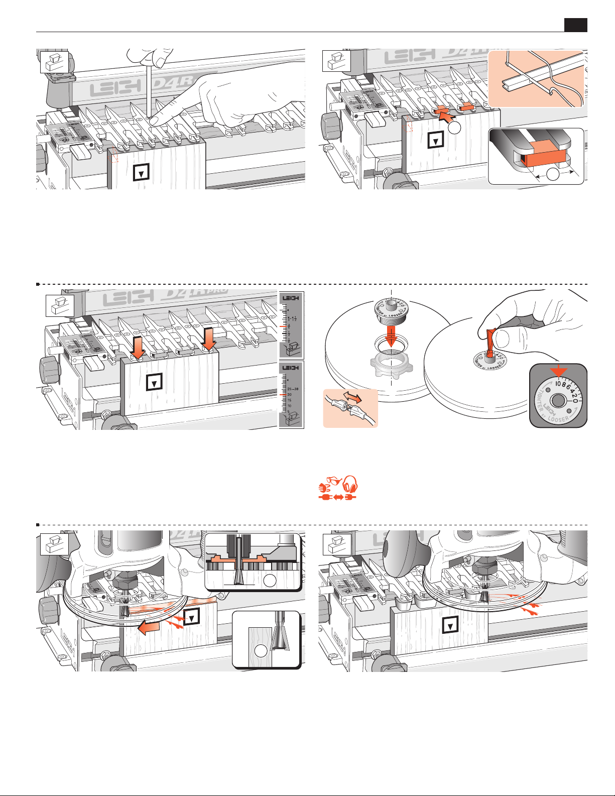
VARIABLY SPACED HALF-BLIND DOVETAILS
Chapter 10D4R Pro User Guide
1
35
2
10 -14 Ignoring the outer guidefinger (router support) at the scale,
loosen enough guides for the desired tail layout. The illustrated half-pin
guidefinger position gives a half-pin socket profile as shown (dotted
lines). NOTE: The first few uses, some fingers may “stick”. This is normal.
3
To “unstick”, loosen the finger screw
⁄4 turn. Press down firmly on the
screwdriver (in the screw) to loosen the finger locking wedge.
10 -16 Remember to tighten any loose guidefingers. Lower the
finger assembly back onto the spacer board and workpiece. It
must touch the workpiece or the depth of cut will vary and the
joint won’t fit. The scale should be set on the tailboard thickness,
3
in this case
⁄4"[20mm].
10 -15 If gaps between the guidefinger tails are wider than about
1
⁄8"[3mm], mark and cut pieces of bridge extrusion
to fit the
guidefinger tail slots. Cut slightly shorter than the space between
the guidefinger shoulders , so guidefingers won’t force apart
with the bridge pieces. Squeeze the open side of the pieces and
push into place for a friction fit.
10 -17 Attach the e7-Bush securely to the router and mount the
supplied No.120-8 bit to the router. Set the e7-Bush to No. 10.
REMEMBER SAFETY!
1
2
10 -18
Adjust the bit height until the bit tip is level with
the marked line . For the first light cut move the
router from right to left. Make sure you control it firmly, because
it is driven in this direction by the bit. Only the tip of the bit
should be cutting on the first cut . This back or climb routing
leaves a very clean shoulder in face grain.
10 -19 Now rout in and out from left to right following the guides
and bridge pieces to rout out the pin sockets, leaving the tails.
See fig. 17-10 “Hints and Tips”.
Page 44
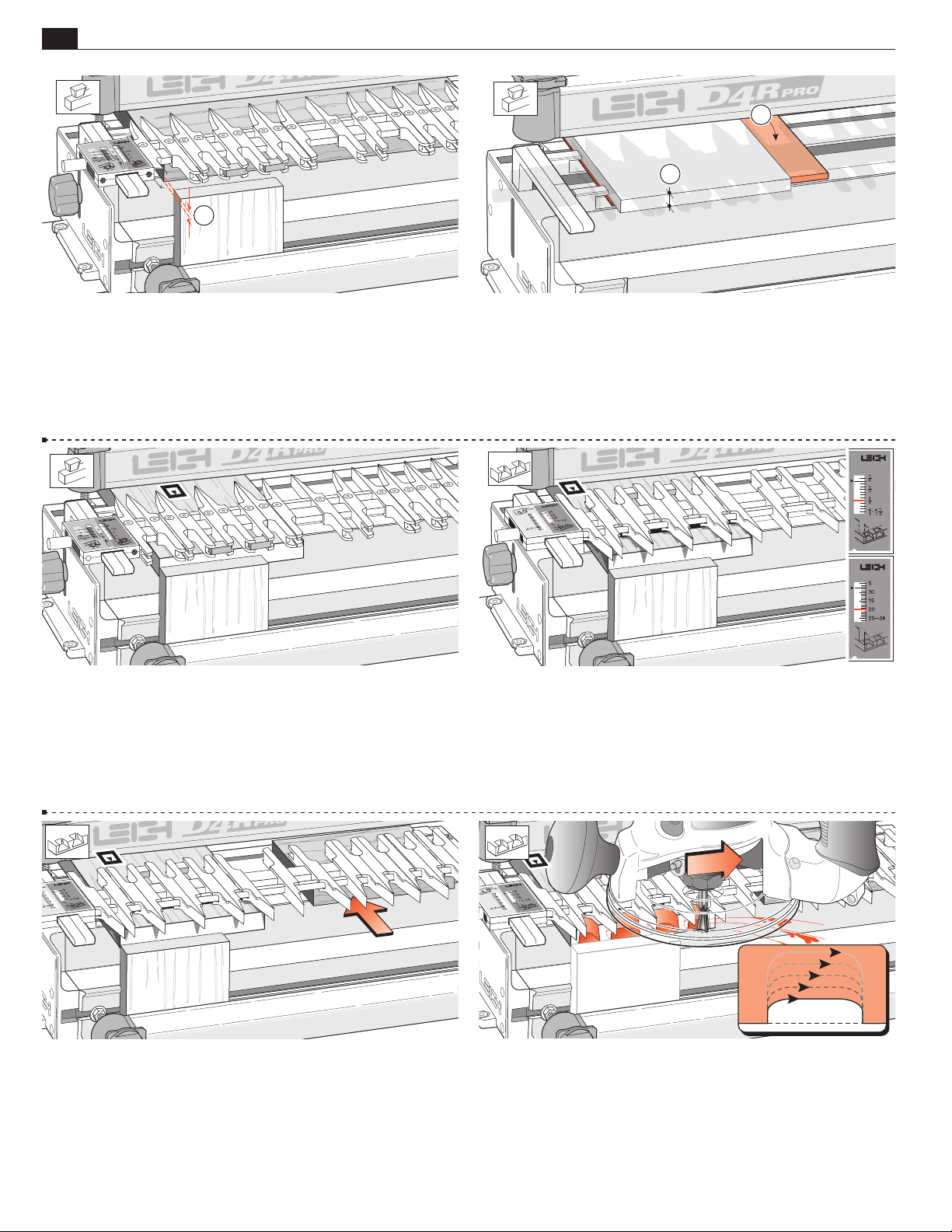
36
Chapter 10 D4 R Pro User Guide
1
VARIABLY SPACED HALF-BLIND DOVETAILS
2
1
10-20 Remove the test tail board, then clamp a scrap board in
the front of the jig so that the top edge projects above the top face
1
of the jig by about
⁄8"[3mm]. This will keep the scrap piece
below the path of the bit when routing the pin board.
Remove the spacer board from the rear clamp.
10-22 Flush Drawers Place a test pin board in the left rear
clamp against the side stop, fitting its front end edge flush against
the vertical scrap piece, inside face
of the drawer front away from
i
the jig body. The pin board is now positioned with the edge to be
routed flush with the jig’s front face, correctly registered for the scale
readings. For drawers with rabbeted fronts, see Chapter 12.
10-21 If you're mounting Thin Pin Boards:
1
The minimum recommended pin board thickness is
⁄2"[13mm]. If
you wish to rout a pin board less than the minimum thickness ,
it will be necessary to pack the board up from the jig body. We
1
suggest using a piece of
⁄4" to 3⁄8"[6 to 9mm] plywood for this
purpose .
10-23 Rotate the finger assembly to the
HB PINS mode. Set
h
the HB PINS scale equal to tail board thickness (i.e., same setting as
3
tails: this example,
⁄4"[20mm]). HB pins and HB tail scales are
always set to tail board thickness. Make sure the finger assembly
is flush and level on the pin board. The guidefingers must touch
the pin board or depth of cut will vary, causing poor joint fit.
10-24 If you have difficulty leveling the finger assembly on a
narrow workpiece, place a board the same thickness as the pin
board under the other end of the finger assembly, but not under
the rear clamp.
10-25
Rout out the waste between the pins. Rout each
space from left to right. Do not back rout on end
grain. If the bit enters on the right side of the opening there will
be a very strong pull to the left, so... Rout each opening in at least
three or four passes, left to right.
Page 45
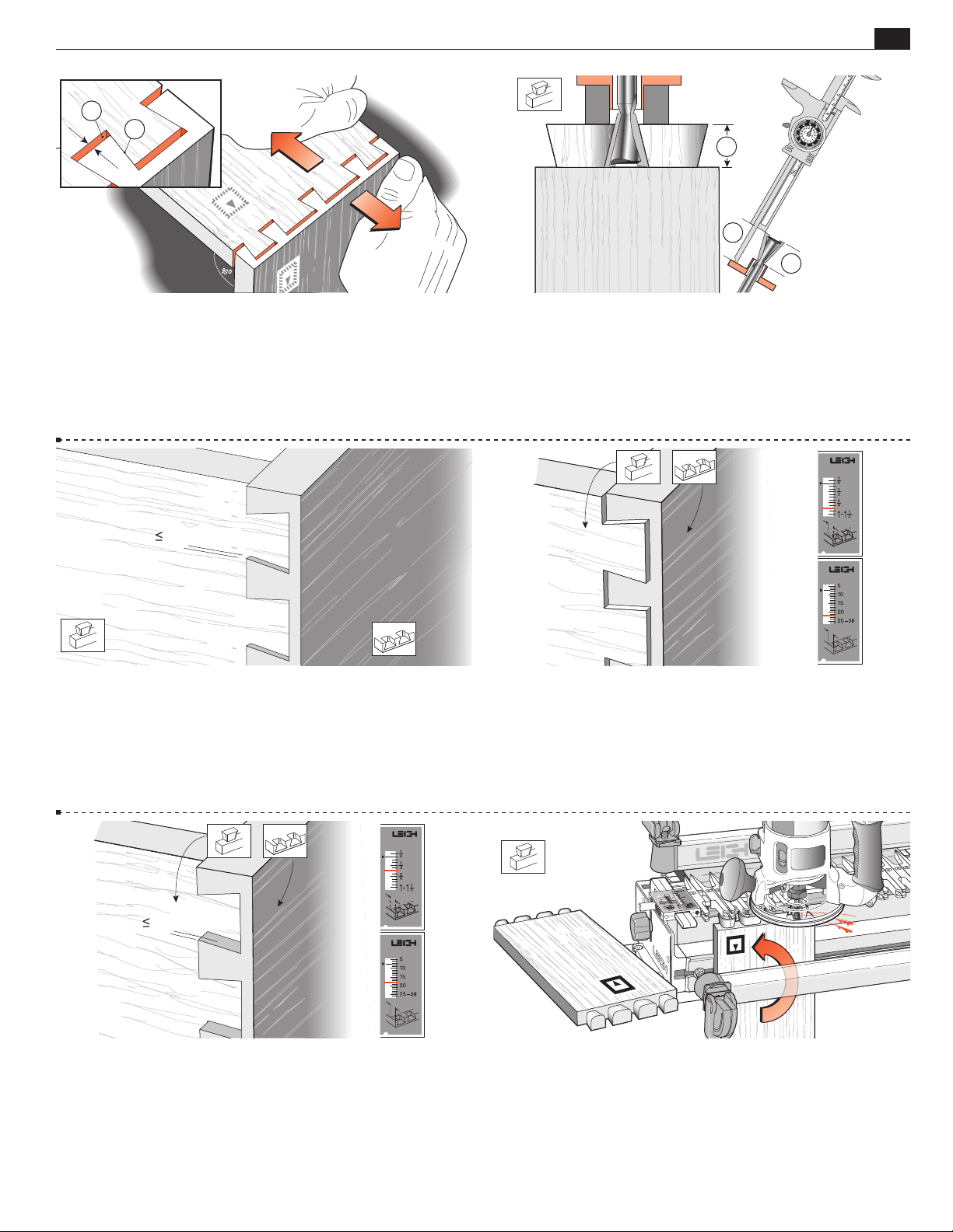
VARIABLY SPACED HALF-BLIND DOVETAILS
1
2
Chapter 10D4R Pro User Guide
1
3
2
37
10-26 Remove the pin board and test the joint for fit. If the
joint is loose, as shown here, you need to lower the bit by the same
amount as the gap at the bottom of the pins (when the pins are
pulled against the socket sides ). If the joint is too tight, raise
the bit slightly. Test again. You cannot rout the same board twice
with a dovetail bit, so use two fresh board ends for each test.
1/64"[0,3mm]
10-28 When you have the proper tightness of fit, check the
flushness. The tails should be under flush to the pins by no more
1
⁄64"[0,3mm] to allow for cleanup (exaggerated here). The
than
concentricity of the collet and guidebush on different routers will
affect this tolerance.
10-27 Keep the test tail board that fits well, and mark it with
the number of the bit you used to rout it. For quick set-up next
time, clamp this tail board in the jig as a depth-of-cut gauge
to
show how far to lower the bit. Better yet, measure the bit projection from the end of the guidebush or guidebush flange and
record this for fast set-ups in future.
10-29 If the tails stand out from the pins, set the
h
HB PINS
scale away from the operator by the amount required.
1/64"[0,3mm]
10-30 If the tails fit in too far past the pins ends, set the
h
HB
PINS scale toward the operator by the amount required. These
adjustments for “flushness” are made only in the
h
HB PINS
mode.
10-31 To make a box, rout all four ends of the tail boards, keeping the inside face
of the tail boards away from the jig.
i
Page 46
38
X
A
A
X
Y
Y
Chapter 10 D4 R Pro User Guide
VARIABLY SPACED HALF-BLIND DOVETAILS
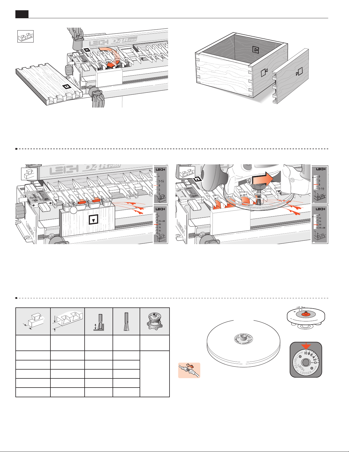
10-32
face
Rout all four ends of the pin boards keeping the inside
of the boards away from the jig.
i
Note: When making drawers you may prefer to use through dovetails
on the rear corners.
QUICK REFERENCE REMINDERS
1
10-34 Half-blind (HB) tails: Drawer sides (tailboards) are clamped
vertically in the jig. The inside face
from the jig body. The finger assembly is in the
of the drawer side goes away
i
HB TAILS
H
mode, set to the thickness of the drawer side. Use bridge pieces
where required .
10-33 Assemble the box. As with through dovetails, it doesn't
matter which edge of any of the boards are at the top or bottom, the
box will still fit together e.g. pin board “A” can be up either way.
10-35 Half-blind (HB) pins: Drawer fronts (pinboards) are
cut with the board clamped horizontally in the jig. The inside
face i of the drawer front faces away from the jig body. The
finger assembly is in the
HB PINS mode, and again set on
h
the thickness of the drawer side (but adjusted for a flush fit, see
10-28 to 10-30).
Thickness of
Tail Board
up to 1"[26]
up to 1"[26]
up to 1"[26]
up to 1"[26]
up to 1"[26]
Thickness of
Pin Board
7
/8" -up [22] ~ 3/4" [19] No.80-8
3
/4" -up [20] ~ 5/8" [16] No.101-8
5
/8" -up [16] ~ 1/2" [13] No. 112-8
9
/16" -up [14] ~ 7/16" [11] No.120-8
1
/2" -up[12] ~ 3/8" [9] No.128-8
Depth of
Cut
Dovetail
Bit
Guidebush
Diameter
Leigh e7
7
or ~
/16"
[11,1]
7/16"[11,1mm]
10-36 On the Leigh D4R Pro, all half-blind dovetails are routed
7
using the Leigh e7-Bush set at No. 10 or standard ~
1
diameter bush (min. depth
⁄4" see Appendix I ). For instructions
to rout end-on-end dovetails see Chapter 13.
⁄16"[11,1mm]
■
Page 47
D4R Pro - CHAPTER 11
Single Pass
Half-Blind Dovetails
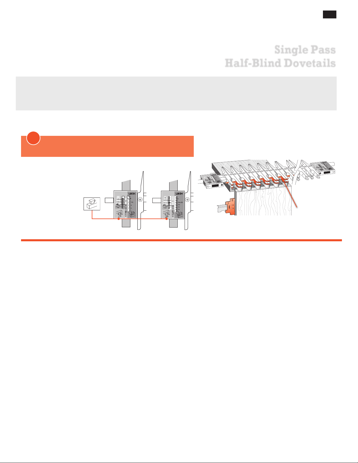
Why rout “single pass” dovetails on a variable spaced Leigh jig? Well, you just may need to reproduce or restore a
late 19th or early 20th century drawer which has similar, machine made joints. Or, if you are making a lot of drawer
boxes and are not so concerned with the traditional “hand cut look”, then routing both drawer fronts and sides
together does go a little faster.
1
Only one mode is required:
Half-Blind Dovetail Tails (HB TAILS) mode
39
MODE ICONS
Illustrations in this manual include the correct
mode icon for the current instruction. The
icons are also used in
the instruction text.
Inches Millimeters
Spacer
Active
Guide Surfaces
Page 48
40
1
6
3
4
2
5
Depth of Cut
Depth of Cut
" [3,2mm] Min.
Board Thickness
Board Thickness
" [3,2mm] Min.
Chapter 11 D4 R Pro User Guide
SINGLE PASS HALF-BLIND DOVETAILS
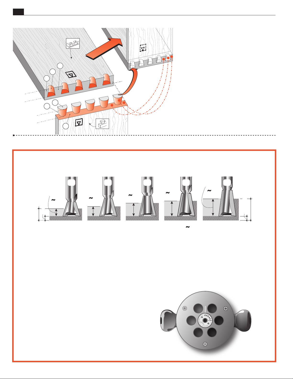
11-1 Single Pass Half-Blind Dovetails:
Pins
h
Pin sockets
Half-pins
Half-pin sockets
Tails
H
Tail Sockets
The pins fit in the pin sockets. Joints should
almost always end each side with half-pins.
11-2 Cutting Depth for Single Pass Half-Blind Dovetails
DEPTH
OF CUT
1
"
/
2
[12,35mm]
80-8
8˚
DEPTH
OF CUT
7
"
/
32
[5,56mm]
8
/
1
Note: Add at least
128-8
18˚
120-8
9
"
/
32
[7,13mm]
14˚
1
⁄8"[3,2mm] to the depth of cut for board thickness.
3
[9,52mm]
112-8
7
"
/
8
12˚
/
[11,1mm]
101-8
"
16
10˚
Symbol for “approximately”
IMPORTANT! Bit depths of cut for “single pass” dovetails
are not the same as for variably spaced joints.
Depth of cut must be as specified for each of the five
•
bits shown above. Exception: See fig.11-26. Note: Leigh
bits 101-8, 112-8 and 128-8 are optional.
Raising the bit above its specified cutting depth will
•
result in loose joints and may damage the jig, bit and/
or guidebush. A lower setting will result in tighter
joints that may not fit together.
Small Depth of Cut adjustments will allow for joint
•
fit tightness. See 10-3 to 10-5 for why.
Fit the provided Leigh e7‑Bush to the router as shown
•
below and set at No.10, or use a standard 7⁄16"[11,1mm]
1
guidebush (min. barrel depth
/4" see page 69).
8
/
1
Choose one of the five, 1⁄2"[12,7 mm] diameter dovetail
•
bits shown above.
Page 49
SINGLE PASS HALF-BLIND DOVETAILS
Chapter 11D4 R Pro User Guide
1
Bit
2
Depth
1
of Cut
2
Projection
41
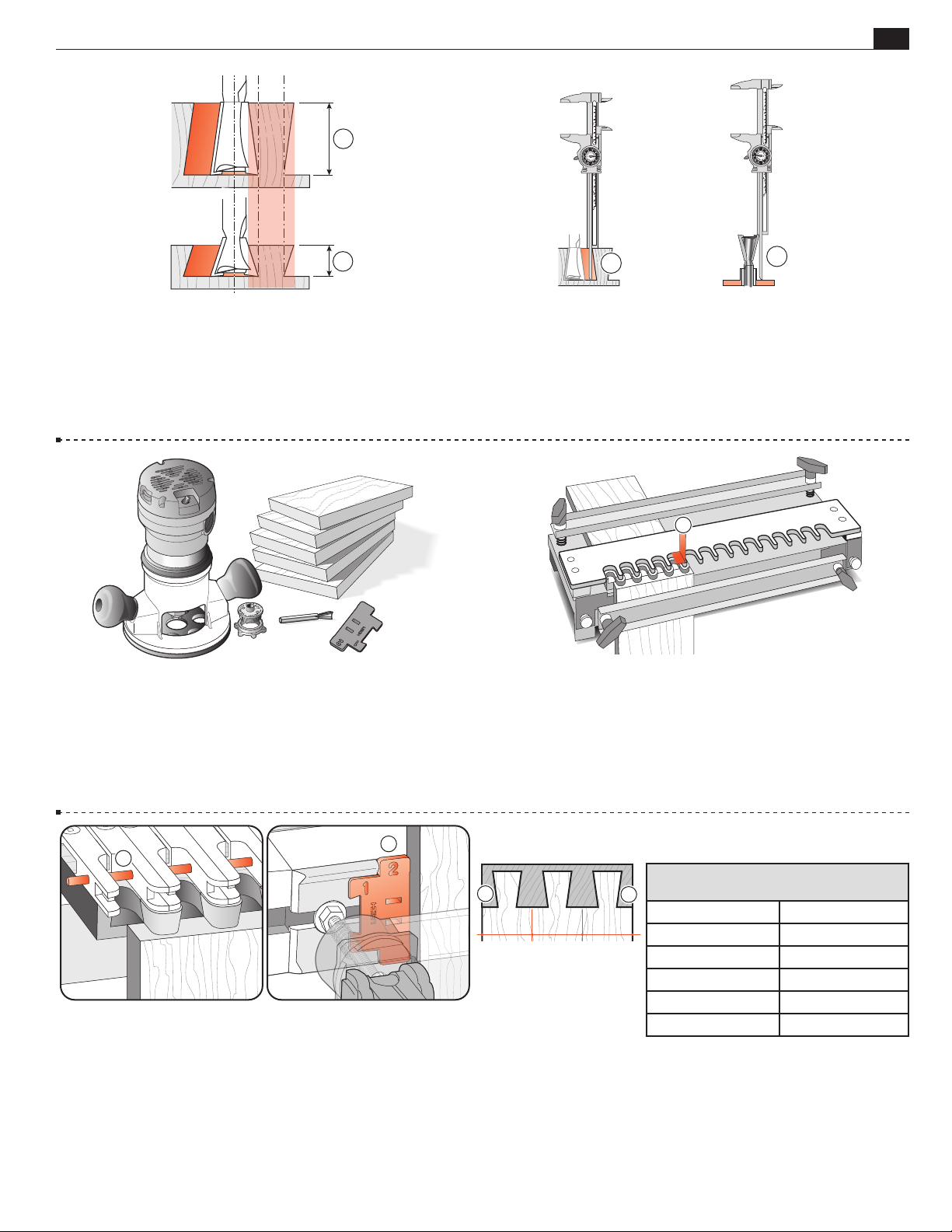
11-3 Bit Angle and Depth of Cut Half-blind pins and tails
are routed with the same dovetail bit, the same guidebush, and
the same depth of cut. A different depth of cut requires a different angled bit. Leigh offers five different angled dovetail bits for
a range of cut depths. A lesser angle, say 8˚, for a deeper cut ; a
greater angle, say 18˚, for a shallower cut .
11-5 Routing a Test Joint You need a router, the e7‑Bush
set at No.10 (see chapter 3 for
1
⁄2"[12,7mm] 8˚ dovetail bit. Note: The No 80-8 bit routs at a
1
shallower ~
⁄2"[13mm] depth on single pass dovetails than on
e‑Bush instructions) and the 80-8
regular variably spaced joints. For this test, start with the No 80-8
15
bit projecting
⁄16"[24mm] from the router base.
11- 4 Cumulative plus/minus tolerances in routers, bits and
guidebushes, make it impossible to state exact bit depth for firsttime precision fit. All dovetail jigs require trial and error tests to
attain a fine fitting joint. The good news; we give a starting depth
for each bit. Test and measure the successful ‘Best fit’ depth of
cut or bit projection and record for future first-time fits.
1
11- 6 This is a typical fixed template comb type jig. The comb
depth is usually dimensioned to suit the most popular drawer
1
side thickness of
⁄2"[12,7mm].
1
2
11-7 Stop Rod and Dovetail Spacer The stop rod is inserted
in the fingers to convert them from deep tail sockets to a shallow
fixed comb. The flexible stop rod is fed through the holes in the
fingers from the “far” end of the jig. The Dovetail Spacer (note
the dovetail shaped notch) snaps into the channel against the lefthand front side stop to correctly offset the drawer sides from
the drawer fronts. After setup, the Spacer stays in place for the
complete procedure.
Single Pass Board Width Chart
1
Add up to ¼" [6mm] or subtract up to 1/8" [3mm]
1
3
⁄16 [55] 8 11⁄16 [221]
2
1
3
⁄4 [83] 9 3⁄4 [248]
3
4
⁄8 [110] 10 7⁄8 [276]
7
5
⁄16 [138] 12 [305]
1
6
⁄2 [166] 13 1⁄16 [331]
5
7
⁄8 [193]
–
11-8 Board Widths To achieve equally sized half pins at
each side on a fixed space joint, use the board width from the chart
1
above. Alternatively, you can add up to
1
width, or reduce it by
maximum width of 13
can be up to 12
⁄8"[3mm]. This chart covers boards up to a
1
⁄16"[331mm]. Example: the 12"[305mm]
1
⁄4"[311mm] or as small as 117⁄8"[302mm].
⁄4"[6mm] to the listed board
Page 50
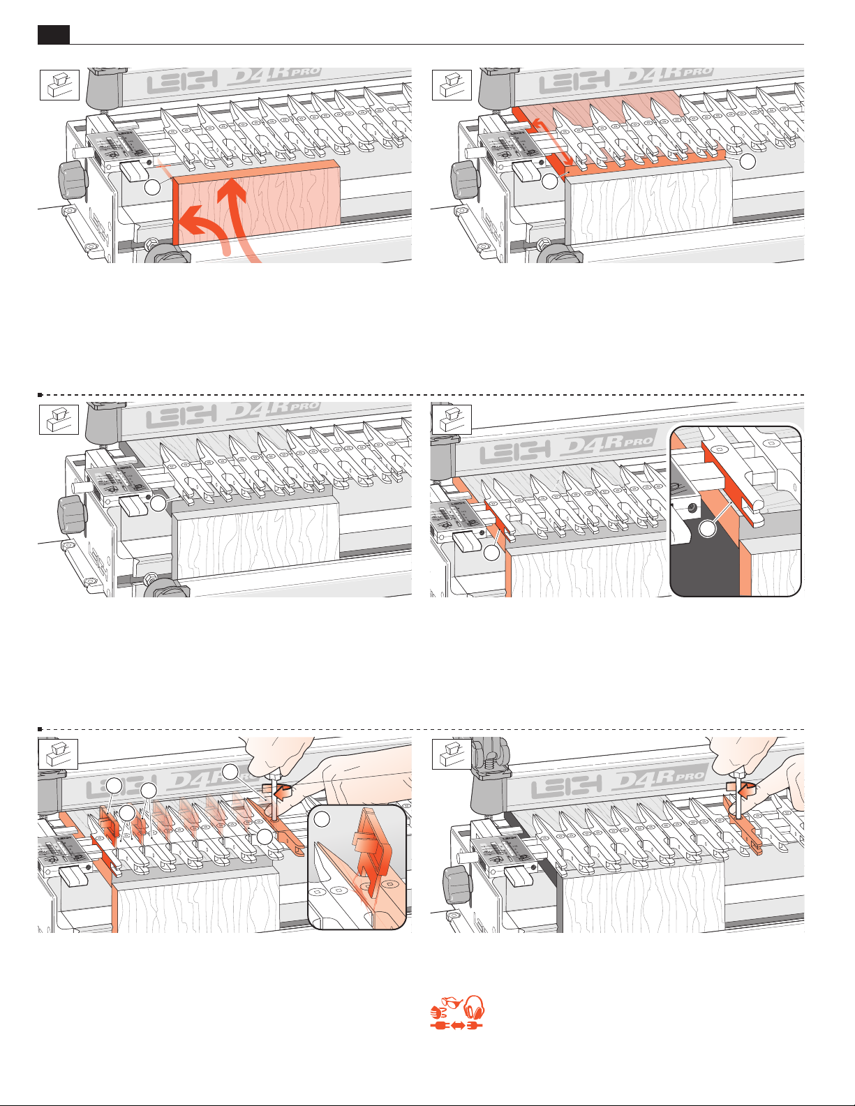
42
Chapter 11 D4 R Pro User Guide
1
SINGLE PASS HALF-BLIND DOVETAILS
1
1
11- 9 With the finger assembly raised in the HHB Tails mode,
clamp a drawer side in the front left side, against the side stop and
the top end edge slightly above the jig body top .
7
Note: Drawer side thickness can be from
⁄16" to 9⁄16"[11mm to
14mm]. See 11-25 re drawer side thickness greater than 9/16".
1
11-11 With the scale set on 1⁄2"[12,7mm], lower the finger
1
assembly to about
⁄8"[3mm] above the drawer front to ease adjust-
ing the guide fingers . The scale is always set on the 1/2" mark
for single pass dovetails.
11-10 Place a sample drawer front from 5⁄8" to 11⁄2" thickness
[16 to 38mm] in the rear clamp. Clamp with the side edge against
the left rear side stop, front end edge touching flush across the
rear of the front board . Note: the 5⁄8" minimum thickness can
be reduced if using other shallower bit depths. ! Board edges must
be square.
2
1
11-12 With boards the same width as a board width chart size
(Fig. 11-8), set the first guide finger flush against the board edge
and tighten. If board width is greater than a chart size, set the first
finger in from the edge by half the additional board width . If
board width is narrower than a chart size, overhang the first finger
by half the difference and tighten.
1
4
2
6
3
5
11-13 Set the dovetail spacer against the guide finger with numeral
facing to the right . Move the next two fingers against the
2
spacer and tighten . Remove and locate the spacer to the right
of the tightened fingers. You should feel some friction removing
it . Slide the next two fingers against the spacer and tighten .
Repeat across the board width plus two more fingers .
11-14 Move any spare fingers so that they will support the router
and tighten all loose fingers.
Lower the assembly flat onto the drawer front.
REMEMBER SAFETY!
Page 51
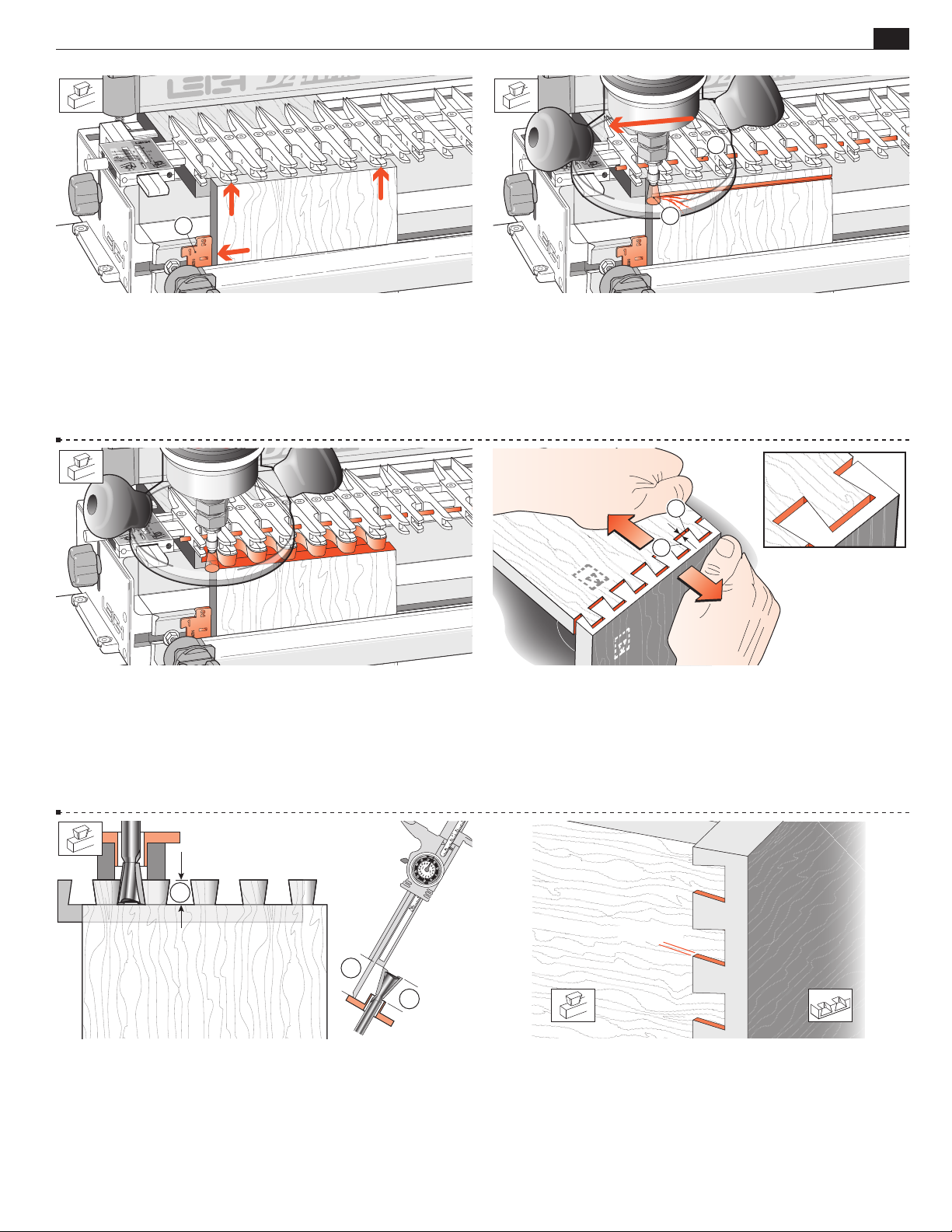
SINGLE PASS HALF-BLIND DOVETAILS
Chapter 11D4 R Pro User Guide
1
43
1
11-15 Unclamp the tail board from the front clamp and insert
the dovetail spacer as shown against the side stop . Re-set the
drawer side in the front clamp so that its top edge touches the
guide fingers and is perfectly flush with the top face of the drawer
front and the left edge is against the Spacer.
! Board edges must be square.
2
11-16 Insert the Stop Rod through the holes in the fingers .
For the first light cut move the router from right to left. Make
sure you control it firmly, because it is driven in this direction
by the bit. Only the tip of the bit should be cutting on the first
. This back, or climb routing, leaves a very clean shoulder
cut
when routing side grain.
1
2
90
o
11-17 Now rout in and out from left to right. Follow the guides
in on the left of each finger opening to touch the stop rod and
come out on the right. The pins, tails and sockets are formed
simultaneously.
1
3
2
11-19 Keep the test tail board that fits well, and mark it with the
number of the bit you used to rout it. For quick set-up next time,
clamp this tail board in the jig as a
depth-of-cut gauge to show
how far to lower the bit. Better yet, measure the bit projection
from the end of the guidebush or guidebush flange and
record this for fast set-ups in future.
11-18 Remove the boards and test the joint for fit. If the joint
is loose, as shown here, lower the bit by the same amount as the
gap at the bottom of the pins when the pins are pulled against
the socket sides . If the joint is too tight, raise the bit slightly.
Test again. You cannot rout the same board ends again with a
dovetail bit, so use two fresh ends for each test.
1/64[0,3mm]
11-20 When you have the proper tightness of fit, check the flushness. The tails should be under flush to the pins by no more than
1
/64"[0,3mm] to allow for cleanup (exaggerated here). Any concen-
tricity errors in the collet and guidebush on different routers will
affect this tolerance.
Page 52
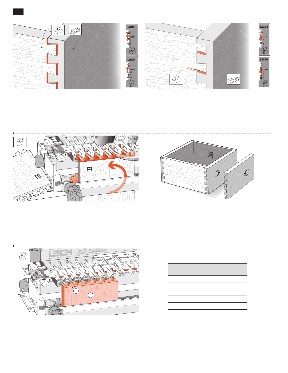
44
Chapter 11 D4 R Pro User Guide
SINGLE PASS HALF-BLIND DOVETAILS
1/64[0,3mm]
11-21 If the tails stand out from the pins, set the HHB TAILS
scale away from the operator by half the amount required.
11-23 To make a box, repeat the procedure four times, ensuring
the drawer fronts, rears and sides are all rotated correctly in the
keeping the inside face i of the boards away from the jig.
jig,
11-22 If the tails fit in too far past the pins ends, set the
HB TAILS scale toward the operator by half the amount
H
required.
Y
A
X
Y
X
A
11-24 Assemble the drawer. As with through dovetails, it doesn’t
matter which edge of any of the boards are at the top or bottom, the
drawer will still fit together e.g. pin board “A” can be up either way.
2
3
1
11-25 For tail (drawer side) boards thicker than 9/16" , set the
1
"
/2
scale to
and leave the stop rod in place. Do not set the scale
to the actual tail board thickness. With thicker boards, more of the
inside portion of the tail board
will be routed away. Slight scale
adjustments may be required for a flush fit. See figures 11-20 through
11-22.
Cutting Depth Increase
Bit
80-8 0.014"
101-8 0.011"
112-8 0.009"
120-8 0.008"
128-8 0.006"
per e-Bush Increment
11-26 Hint: Increasing the Depth of Cut (see page 40) This is
based on setting the e-Bush on 10. The depth of cut for each bit
can be increased slightly by turning the e-Bush to a lower number.
For example, if you turn the e-Bush from 10 to 9 you will have to
increase the depth of cut by 0.014" for the 80-8 bit. If you turn
the e-Bush two increments to number 8 you will have to increase
the depth of cut by 0.028" and so on.
■
Page 53
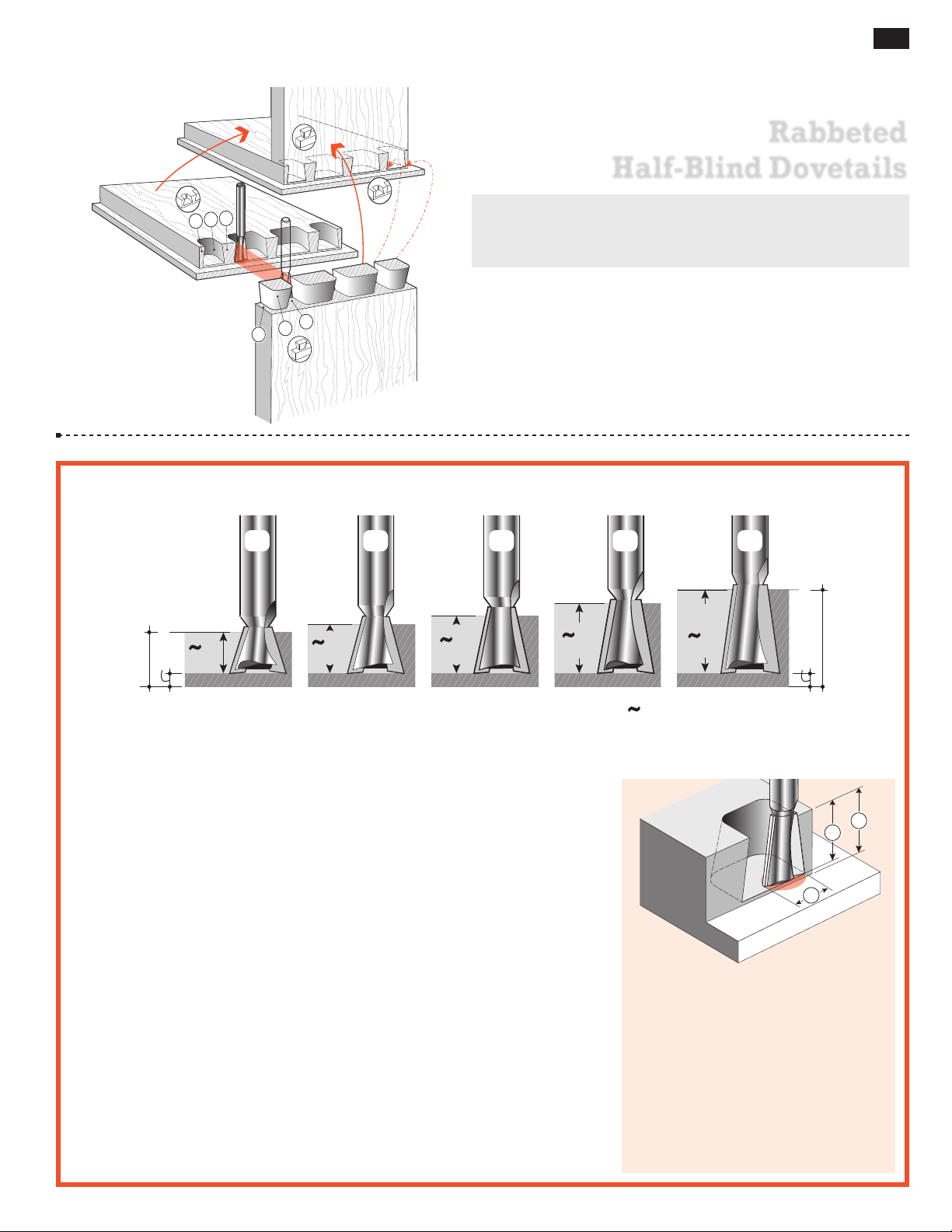
45
1
6
3
2
4
5
" [3,2mm] Min.
Board Thickness
" [3,2mm] Min.
Board Thickness
D4R Pro - CHAPTER 12
Rabbeted
Half-Blind Dovetails
Before attempting rabbeted half-blind dovetails, first
master the techniques of flush half-blind dovetails in
chapter 10.
12-1 Rabbeted Half-blind Dovetail Terminology:
Pins
h
Pin sockets
Half-pins
The pins fit in the pin sockets. Joints should almost always end
each side with half-pins.
Half-pin sockets
Tails
H
Tail Sockets
12-2 Cutting Depth for Rabbeted Half-Blind Dovetails
DEPTH
OF CUT
3
/8"
8
/
[9mm]
1
Note: Add at least
128-8
18
˚
120-8
7
/16"
[11mm]
14
˚
1
⁄8"[3,2mm] to the depth of cut for board thickness.
[13mm]
112-8
1
/2"
12
˚
[16mm]
101-8
DEPTH
5
/8"
10
˚
OF CUT
[19mm]
Symbol for “approximately”
80-8
3
/4"
8
˚
Important! Read This About Rabbeted HB Depth of Cut
Bit selection is critical. You need to select
a specific dovetail bit for your rabbeted
half-blind dovetail project, depending on the rabbet depth you are using.
• Choose one of the five 1⁄2"[12,7mm]
diameter dovetail bits shown above.
See bit selection in Appendix II.
• Depth of cut must be as specified for
each of the five bits illustrated above.
Exception: See fig.11-26. Note: No’s
101-8, 112-8 and 128-8 are optional
Leigh bits.
• Raising the bit above its specified
cutting depth will result in loose
joints and may damage the jig, bit
and/or guidebush. A lower setting
will result in tighter joints that may
not fit together.
• Small Depth of Cut adjustments
will change joint fit tightness. See
10‑3 to 10‑5 for why.
• Rabbeted Half‑blind PINS and
TAILS are routed with the same
dovetail bit and must be at the same
Depth of Cut.
• All half‑blind dovetail bits work
with the Leigh e7‑Bush supplied
with your Leigh jig or a standard
7
⁄16"[11,1mm] outside diameter
guidebush.
RABBET DEPTH determines the
maximum depth of cut you can
use. Select a bit with a specified cutting
depth that is at least 1/16"[1,6mm] less
than the rabbet depth.
A dovetail bit will produce only one
specific cutting depth.
Only 1⁄2"[12,7mm] cutting diameter bits
can be used for half-blind dovetails.
8
/
1
1
2
3
Page 54
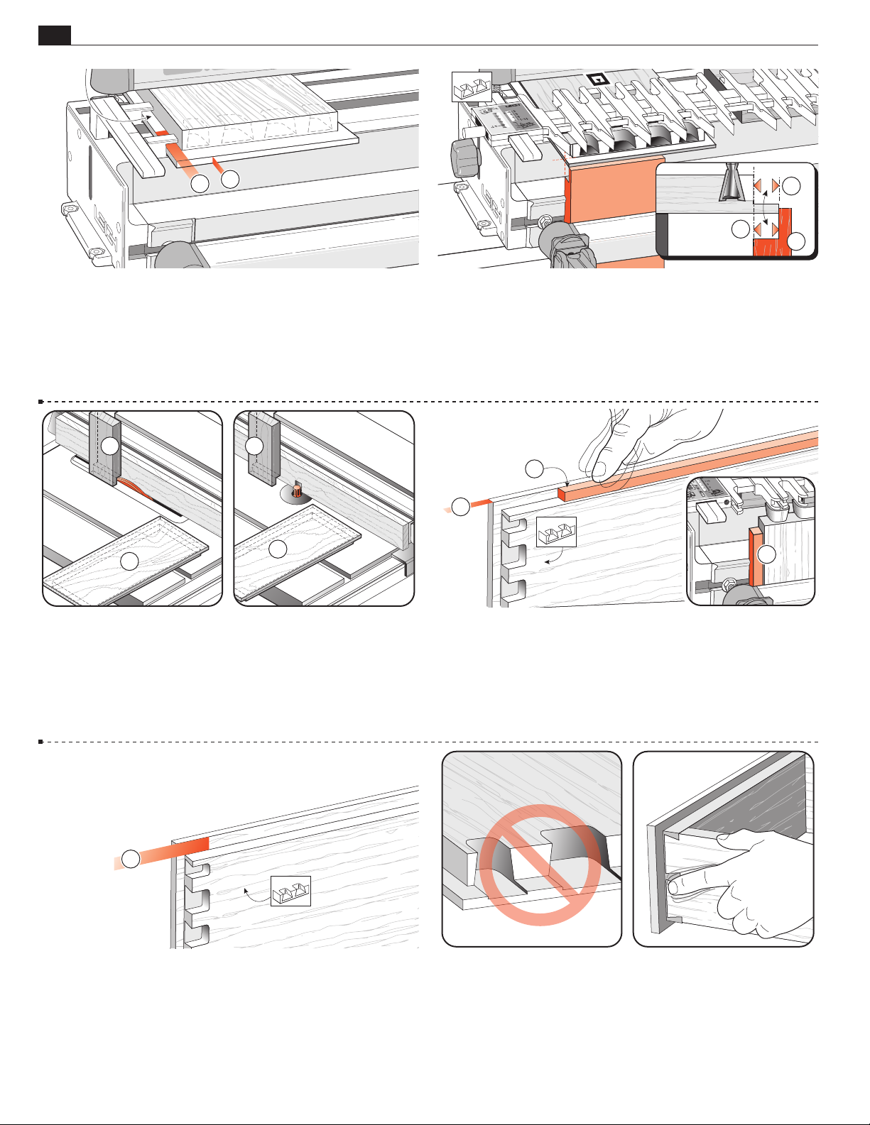
46
1
2
Chapter 12 D4 R Pro User Guide
1
2
RABBETED HALF-BLIND DOVETAILS
=
2
3
=
1
12-3 Provided the drawer front lip is 3⁄8"[9,5mm] or less in thick-
ness , you can mount and rout rabbeted drawer fronts and sides
exactly the same way as flush drawer fronts. If the lip is thicker or
3
wider than
⁄8"[9,5mm] see 12-6 thru 12-8.
1
2
12-5 An easy accurate way to do this is to rabbet the end of a scrap
piece
vertically over a dado blade or router bit at the same time
as you rabbet the drawer front (horizontally) .
12-4 Rabbeted Pins You will need to clamp a scrap stop block
in the front of the jig out from the jig’s front face by exactly the depth
of the rabbet
.This brings the pin ends exactly in line with the
front jig face , ensuring that the scale reading is accurate.
2
1
3
12-6 If the lip thickness is greater than 3⁄8" [9,5mm], it will not
fit under the side stop. Block the drawer side away from the front
side stop by exactly rabbet depth (see 12-3
). Make up a block and
stick it to the jig face with double-sided tape. Make sure it touches
the side stop. This will offset the drawer side from the side stop by
the width of the rabbet, and align the sockets with the pins.
1
12-7 If the rabbet width is greater than 3⁄8"[9,5mm], the drawer
side must be offset from the front side stop by the depth of the
3
rabbet minus
⁄8"[9,5mm]. Make up a block to this measurement
and stick it to the face of the jig, touching the front side stop. This
will offset the drawer side away from the side stop and align the
sockets with the pins.
12-8 Make sure you select a dovetail bit that has a working depth
of cut less than the rabbet height. Otherwise, you will rout into the
rabbet.
It is difficult to clean up the drawer sides and front corner after
assembling a rabbeted drawer, so make sure the fit is flush before
you complete the drawers (see 10-28 to 10-30).
■
Page 55
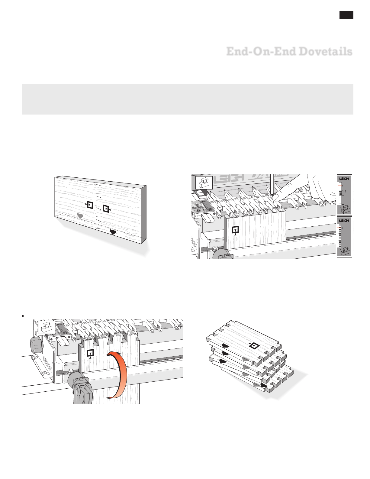
D4R Pro - CHAPTER 13
End-On-End Dovetails
While you have the router set up for half-blind dovetails, it is a good time to try end-on-end dovetails.
If you have not yet routed half-blind dovetails or read through chapter 11, please do so now before
attempting end-on-end dovetails.
47
1
2
3
4
1
2
1
4
13-1 End-on-end dovetails are made in the same modes as halfblind joints, but both boards are routed vertically in the front clamp,
alternately face side in and then face side out
3
on-end joints may be up to
⁄4"[20mm] thick.
. Boards for end-
j
Use only the guidebush, dovetail bits and depths of cut as
specified in 10‑32.
25–38
20
15
10
5
13-2 The end-on-end dovetail is laid out in the H HB TAILS
mode. There is a special mark on the scale for end-on-end dovetails.
Align the support bracket line with the small arrow as shown. Adjust
the guidefingers as required.
13-3 Rout the tails. Clamp end-on-end dovetail boards in the jig
for routing one end face side in and one end face side out. Keep
the same edge against the side stop for both ends.
13- 4 Rout the tails on each end of the tail boards.
Page 56
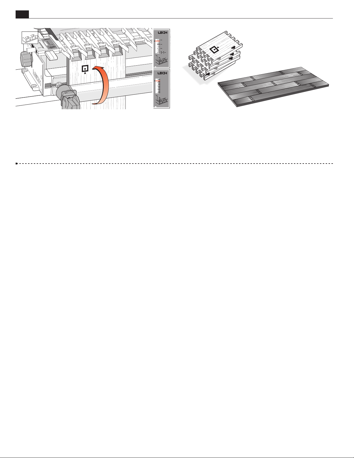
48
Chapter 13 D4 R Pro User Guide
1
4
1
2
3
4
1
2
5
10
15
20
25–38
END-ON-END DOVETAILS
13-5 Rotate the finger assembly to
on the small scale arrow for maximum pin board thickness (
HB PINS mode and again set it
h
3
⁄4"[20mm]).
There is no theoretical minimum thickness, but avoid thin board tearout,
see 17-11. Rout pins on each end of pin boards, same edge against the
sidestop for both ends. Narrow pins are illustrated (look like narrow
tails), but guidefingers can easily adjust for even-sized tails and pins.
13- 6 Always assemble end-on-end joints keeping the edges of
the boards that were against the side stop all in line.
Applications for End-on-End Dovetails
As one example, you can make a flat, stable, and attractive chest lid
by edge-jointing and glueing end-on-end dovetailed boards.
■
Page 57
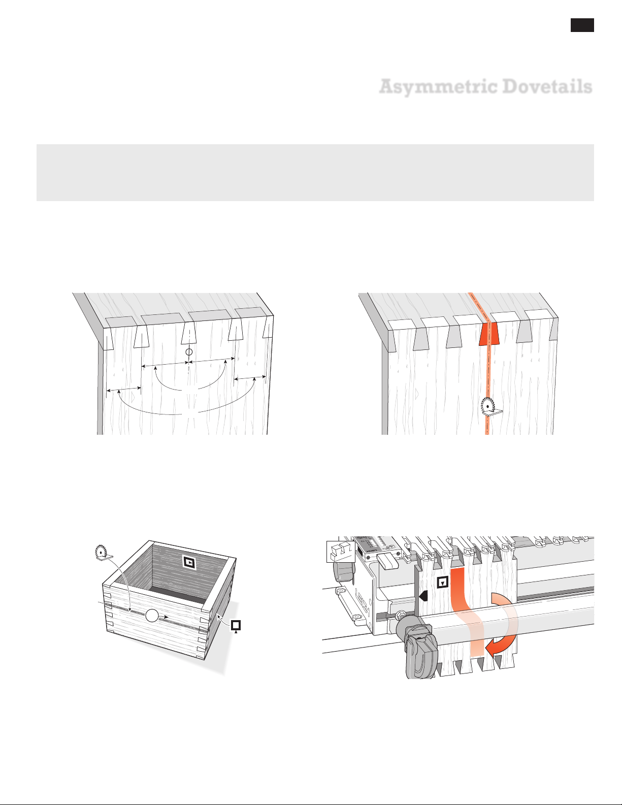
D4R Pro - CHAPTER 14
Asymmetric Dovetails
For certain procedures, you will need to use both ends of the Leigh D4R Pro jig. Asymmetrical joint layouts are one
example. On the Leigh Jig, no joints will be truly symmetrical, but they can look symmetrical. Apparent symmetry
is only required for aesthetic reasons, and not for strength. Be sure you have read and understood chapters 8
through 14 before attempting these procedures.
49
~=
~=
14 -1 By symmetrical we mean a joint that looks or is approximately
symmetrical about its center line but is probably not, and need
not be precisely symmetrical. Using the Leigh jig, it is easy to cut
a joint that looks symmetrical; the pins will always align perfectly
with the tails cut at the same spacing. Remember, symmetry is
only required for appearance, not for joinery reasons.
1
14-2 By asymmetrical we mean a deliberately uneven layout of
pins and tails required by the project design. For example, asymmetrical joints may be used for blanket chests or boxes. One pin
is made wider for a saw-cut allowance…
14-3 So the chest and lid half-pins all look the same width after
the lid portion is cut off.
14-4 In the chest example you can see that if both ends of the
board are cut under the same guidefingers, the wide sockets and
pins at opposite ends will not line up. Remember, the same inside
of the through dovetail tail board has to face away from
face
i
the jig for each cut.
Page 58
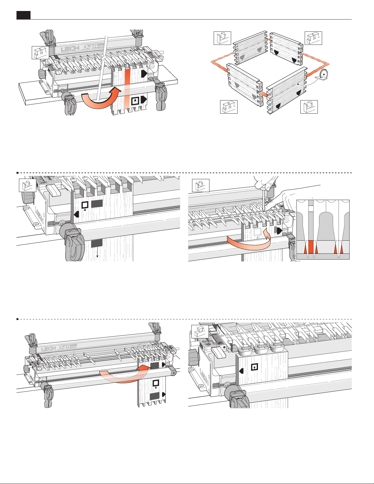
50
Chapter 14 D4 R Pro User Guide
ASYMMETRIC DOVETAILS
C
C
B
D
14-5 Deliberately asymmetrical joints must therefore be routed
on both ends of the jig using two separate, almost mirror-image
layouts.
A/C
B/D
B
A
A
D
14-6 The layouts need not be exact mirror images because the
parts that fit together will be made on the same end of the jig.
For a typical blanket chest you would rout corners A and C on
one end of the jig and corners B and D on the other end. As long
as the side stop marks all face up (or all down), the box will go
together.
14-7 Here is an easy way to cut these near-mirror-image joints.
Lay out the A and C corner joints in the usual way (i.e., in the
TD PINS mode). Rout the A and C corners’ tails and pins.
d
Leave the guidefingers set and in the
TD PINS mode.
d
B/D
A/C
14-9 Now rout the B and D corners’ tails and pins using this
guidefinger pattern. When you assemble the case, the A and/or C
ends will fit each other, and the B and/or D ends will also fit each
other. Keep the boards inside face i inwards on the case and the
side stop edges all turned the same way, and the parts are sure to
match (see 14-6).
14-8 Simply flip a completed A or C pin board from one end of
the jig (like turning a page) to the other end, and center each pair
of guidefingers over a pin.
14 -10 To transfer a mirror image asymmetrical half-blind
joint…
Page 59
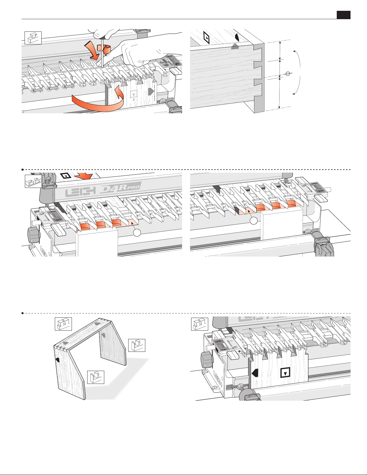
ASYMMETRIC DOVETAILS
=
Chapter 14D4R Pro User Guide
51
/
14 -11 Turn the tail board (like turning a page of a book) to the
other end of the jig. Position the guidefingers over the tails, then
rout the tails for the other drawers.
This tail board layout may look symmetrical, but as the next
illustration shows, it forms part of an asymmetrical joint.
1
14 -13 Mount the right end of the drawer front on the left end,
but do not rout this opening .
14 -12 This common example of asymmetry is where boards are
of a different width. In this case, a drop-front drawer, the drawer
front bottom half-pin is much wider than the top half-pin. The
top edges of the drawer front and sides are flush, so it makes sense
to use these edges against the side stops at each end of the jig.
2
14-14 Mount the left end of the drawer front on the right end,
using the
mirror‑image layouts on both ends, but do not rout this
opening .
14 -15 Both ends of the jig are also used for the top corners of a
slant-front desk. The joints themselves may be symmetrical, but
they must be routed on opposite ends of the jig because the sloped
front will not register accurately against the fixed side stops.
14 -16 At the back of the desk both sides and top are flush, so
the rear edges are set against the side stops. Place the left end of
the top tail board against the left side stop
. Rout the tails.
e
Page 60
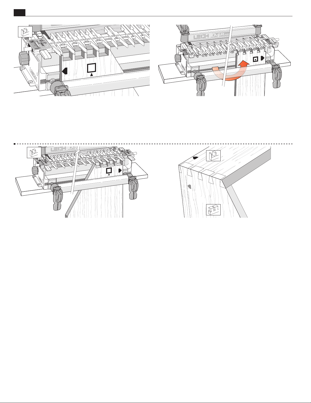
52
Chapter 14 D4 R Pro User Guide
ASYMMETRIC DOVETAILS
14 -17 The left side of the desk goes against the left side stop e.
Rout the pins.
14 -19 Place the right side of desk against the right side stop f.
Rout the pins.
14 -18 Transfer the joint layout from left to right (as for 14-8
to 14-11) and place the right end of the top tail board against the
right side stop f. Rout the tails.
14-20 Note: If, in the slant-front desk example, the pins were in the
desk top and the tails in the sides, then all the parts would be routed
in the opposite ends of the jig to those shown above.
■
Page 61
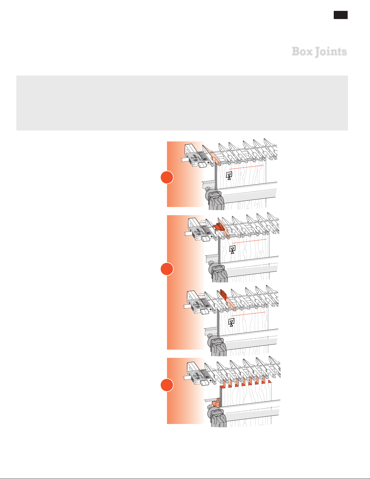
D4R Pro - CHAPTER 15
Box Joints
IMPORTAN T: “Actual” Joint Sizes
The D4R Pro finger assembly was originally designed solely for dovetailing. Adapting the assembly for box jointing
was a serendipitous combination of luck (existing guides approximately the correct dimension) and clever design;
the e7-Bush and Spacer. As a result, the nominal 3⁄8" and 3⁄4"[9,5 and 19 mm] box joint sizes are closer to 25⁄64"
49
⁄64" [9,8 and 19,6mm] respectively.
and
53
Concept of Operation
The first board is set against the side stop .
The Spacer is used to space the guide fingers .
1
1
2
The Spacer is also used against the side stop to
accurately offset mating work pieces for correct board
to board joint alignment.
3
Page 62
54
Chapter 15 D4 R Pro User Guide
Choose your Board Width:
Symmetrical joints: Use the red column
Asymmetrical joints: Use the grey column
Count the total sockets and pins in the first column
Board Width - INCHES Board Width - MILLIMETERS
3/8" 3/4" 9,5mm 19mm
Symmetrical Symmetrical Asymmetrical Symmetrical Asymmetrical SymmetricalAsymmetrical Asymmetrical
BOX JOINTS
1
2
3
4
5
6
7
8
9
10
11
12
13
14
15
16
17
18
19
20
21
22
23
24
25
26
27
28
29
30
31
32
33
34
35
36
37
38
39
40
D4R Pro
41
1 1/
1 29/
2 11/
3 15/
4 7/
5
3
5
/
6 17/
7 5/
8 3/
8 7/
9 19/
10 13/
11 3/
11 31/
12 3/
13
14 9/
15 1/
15 27/
1
8
1
/
2
1
32
2 9/
16
32
32
4
32
16
32
8
32
16
4
1
/
2
32
16
32
3 1/
16
3 27/
32
4 5/
8
5 3/
8
6 5/
32
6 15/
16
7 23/
32
8 17/
32
9 1/
4
10 1/
10 13/
11 9/
12 11/
13 1/
13 29/
14 11/
15 7/
16 7/
32
16
16
32
8
32
16
16
32
32
32
32
2
3
2 9/
32
4
5
3 27/
6
7
5 3/
8
9
6 15/
10
11
8 17/
12
13
10 1/
14
15
11 9/
16
17
13 1/
18
19
14 11/
20
21
16 7/
1
3
/
16
32
4 5/
8
8
6 5/
32
16
7 23/
32
32
9 1/
4
32
10 13/
16
16
12 11/
32
8
13 29/
32
16
15 7/
16
32
1
2
3
29
4
5
49
6
7
68
8
9
88
10
11
107
12
13
127
14
15
137
16
17
167
18
19
186
20
21
206
22
23
225
24
25
245
26
27
265
28
29
284
30
31
304
32
33
324
34
35
343
36
37
363
38
39
383
40
41
402
39
59
78
98
117
137
157
176
196
216
235
255
275
294
314
334
353
373
393
412
1
2
59
3
4
98
5
6
137
7
8
176
9
10
216
11
12
255
13
14
294
15
16
334
17
18
373
19
20
412
21
78
117
157
196
235
275
314
353
393
Page 63
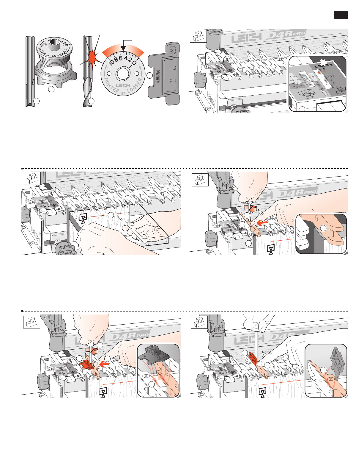
BOX JOINTS
Chapter 15D4R Pro User Guide
5
1
3
1
21
55
1
15-1 Bit and Guidebush selection Only the e7‑Bush and the
5
⁄16" bit that came with the D4R Pro are required for box joints.
Spiral upcut router bits will cut cleaner than straight flute. Where
metric size bits are available an 8mm straight or spiral bit may be
5
substituted for the
⁄16". Always start test routing with the e7‑Bush
set on “5”. Note: the box joint Spacer has a square notch.
1
15-3 Clamp a test board in the front left clamp, against the side
stop with the top edge flush under the guidefingers. The board
may be clamped face side in or out
. Mark and adjust the depth
j
of cut to suit the thickness of the mating boards .
15-2 3⁄8"[9,5mm] Box Joints.
Place the finger assembly on the support brackets in the HB TAILS
mode, set the scales on the small triangular arrow
and lower the
assembly onto the spacer board. All box joints are routed in this
position. Note: maximum board thickness is 1"[25mm]
1
3
2
2
15-4 Raise the finger assembly about 1⁄8"[3mm] to allow ease
of guide finger adjustment . Position the second guidefinger
1
⁄32"[1,0mm] in from the board edge and tighten the finger. The
first finger stays against the scale block as a router support .
Note: Square ended boards are essential to achieve flush joint alignment.
3
1
2
4
15-5 Place the Spacer on the finger bar to the right of the second
finger, numeral 1
on top overlapping the locked finger . Move
the next finger in to touch the Spacer . Hold the guidefinger
firmly against the Spacer and tighten the second finger screw .
As you remove the Spacer you should feel some friction; this
indicates that the guidefinger is correctly spaced .
1
2
3
15-6 Now place the spacer vertically on the right hand side of
the third finger; the prongs to the left . Hold the guidefinger
firmly against the Spacer and tighten the second finger screw .
As you remove the Spacer you should feel some friction ; this
indicates that the guidefinger is correctly spaced.
Page 64
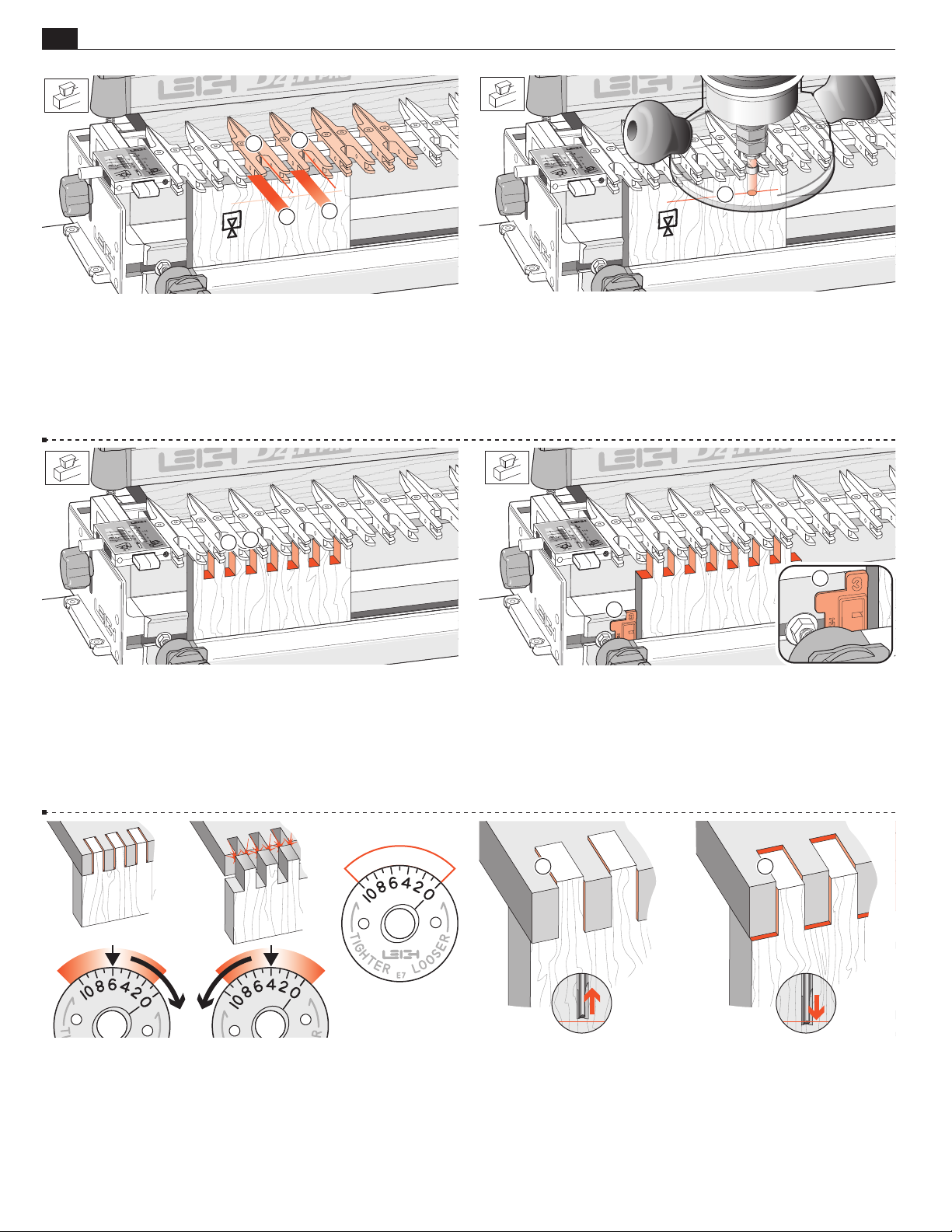
56
Chapter 15 D4 R Pro User Guide
2
2
1
1
BOX JOINTS
1
15-7 Repeat this procedure across the jig until there is at least
one guidefinger spaced past the right hand side of the work piece.
1
Finger pairs should have a uniform
⁄2"[12,7mm] space between
them , and .054"[1,37mm] gap between fingers of the same
pair. Tighten the unused guides.
2
1
15-9 Rout one end of the scrap board. Rout into each finger
opening and between each finger . Make sure to run the
guidebush on both sides of each opening.
15-8 Lower the finger assembly onto the spacer board and doublecheck that the bit depth is down to the center of the pencil line .
Make sure the collet does not rub on the guidebush.
1
1
15 -10 Remove the board and fit the box joint Spacer against
the front side stop with the number 3 showing
. Make sure
it is fully home. Clamp the second test board with its side edge
against the Spacer and its top edge touching the guidefingers.
Rout this board. Note: Square ended boards are essential to achieve
flush joint alignment.
15 -11 Test the boards for fit and flushness. If the joint is loose, turn
the e7‑Bush to a higher number and rout two more boards. If the
joint is too tight, turn the e7‑Bush to a lower number. Trial-and-error
establishes the best e7‑Bush setting. Record it on this bush drawing for
a good result the next time. Note: each increment adjusts glue line fit by
0.002"[0,05mm]. Retighten the e-Bush nut after each adjustment.
1 2
15 -12 If the joint is over-flush , raise the bit slightly. If it is
under-flush , lower the bit.
Page 65
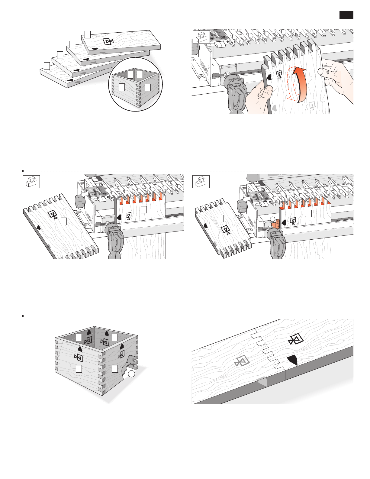
BOX JOINTS
1
2
3
4
2
3
Chapter 15D4R Pro User Guide
57
1
15-13 Lets make a box with 3/8" box joints..
Prepare four boards and number them 1 to 4. Then select the grain
alignment and mark the common top (or bottom) edge
worry about face side selection; this can be done after routing.
4
. Don’t
f
3
1
15 -14 All box joint boards are clamped alternating face side in j
and face side out
side stop (or Spacer).
2
always with the same side edge against the
j
1
4
15-15 Rout both ends of boards 1 and 3 with their edges against
the side stop. Be sure to keep the same edge to the stop.
2
1
15 -17 Keeping the marked side stop edges of all boards toward the
top (or all to the bottom) of the box, select the preferred outside
faces before routing the grooves for the bottom.
3
4
5
15 -16 Rout both ends of boards 2 and 4 with their edges against
the Spacer and the Spacer in the No 3 position.
Keep the same edges to the Spacer.
15 -18 The same method will produce end-on-end joints.
Page 66
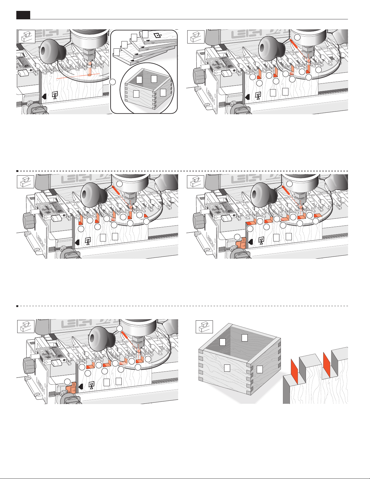
58
4
Chapter 15 D4 R Pro User Guide
BOX JOINTS
3
2
1
4
1
15-19 3⁄4"[19mm] Box Joints Set-up and space the guide
3
fingers exactly as for
⁄8"[9mm] joints. Start with the same e7‑Bush
setting. See 15-2 thru 15-9.
Prepare four boards using the board width chart for
joints and number them 1 to 4
around the box with the com-
mon edges marked.
3
3
2
1
3
⁄4"[19mm]
3
2
2
2
2
2
1
1
3
1
1
1
15-20 Rout both ends of boards 1 and 3 but only rout between
the guide finger openings not between the finger sides . Keep
the common edge against the side stop.
Mark the router base at the 12 o’clock position and steer
Hint:
this mark along the pointed ends of the fingers at the rear of the
assembly.
3
1
2
2
2
4
2
2
2
1
1
1
15-21 Now rout both ends of boards 2 and 4, with the common
edge against the side stop but only rout between the finger sides
not between the finger openings .
Hint: Now steer the base 12 o’clock mark between the pairs of
finger points
.
3
2
2
2
2
2
4
1
1
3
1
1
1
1
1
2
4
2
2
4
2
2
2
1
1
15-22 Remove the board and fit the Spacer to the side stop with
number 3
showing . Now rout both ends of boards 2 and 4 again,
with the common edge against the Spacer and again …only rout
between the finger sides
, not between the finger openings ,
steering the router mark between the pairs of finger points .
2
4
1
3
15-23 With the Spacer still in position rout both ends of boards
1 and 3, with the common edge against the Spacer and only rout
between the finger openings
the finger points .
, steering the router mark along
15-24 Joint fit Check for joint fit as usual, and repeat testing
3
if required. Theoretically, there will be nothing in the
⁄4"[19mm]
sockets, literally a zero thickness wall, where the bit has passed by
twice. However, routing tolerances can leave a very thin “wall”
uncleared by routing. This can be quickly removed with a chisel
or sandpaper.
■
Page 67
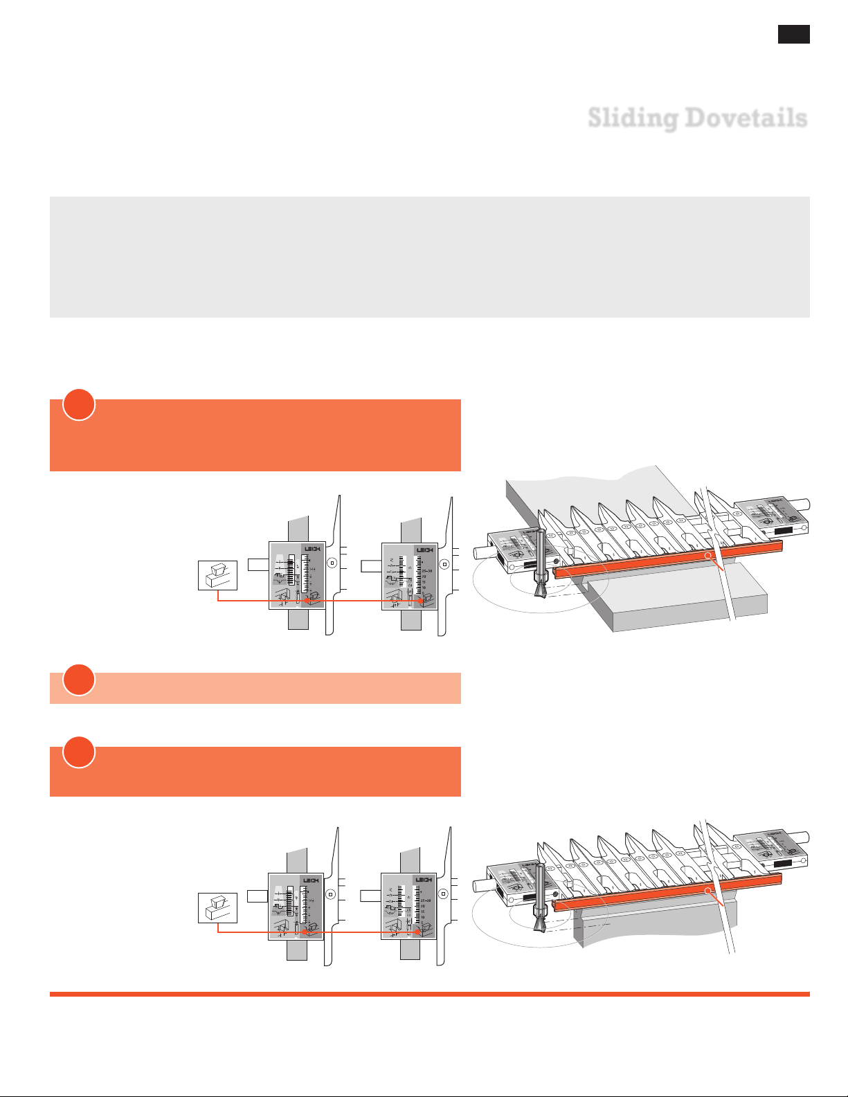
D4R Pro - CHAPTER 16
Sliding Dovetails
Routing sliding dovetail “slots” across the face grain of horizontal boards is very tough on dovetail bits.
Always use the largest shank size available to you; we recommend at least 8mm shanks, but 1⁄2" would be
even better, with of course the appropriate guidebush.
If you have to use 1⁄4" shanks in hardwood, use a second router to rough out the slot centre with a straight bit.
While we recommend 5⁄8"[15,9mm] as the ideal size guidebush for sliding dovetails, we appreciate that many users
will have only a 7⁄16" bush. These instructions cover both those guidebushes.
1
With the Finger Assembly in
HALF-BLIND DOVETAIL TAILS (HB TAILS) mode,
install the cross-cut fence
59
Sliding Dovetail
Inches Millimeters
slots are cut
across the board
face.
2
KEEP the finger assembly in the same mode
3
Sliding Dovetail tails
are cut across the board end edge
Inches Millimeters
Active
Guide Surface
Active
Guide Surface
Page 68
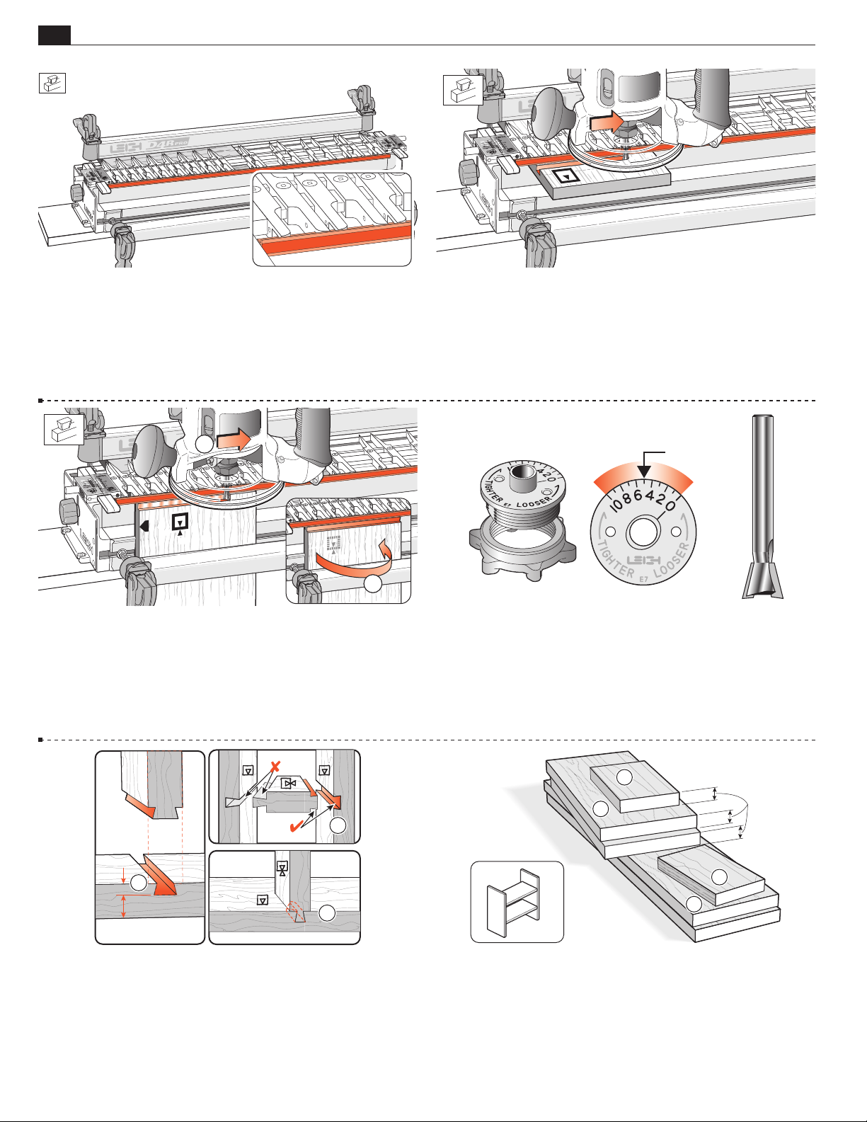
60
Chapter 16 D4R Pro User Guide
SLIDING DOVETAILS
16 -1 With the finger assembly in HHB TAILS mode, the cross
cut fence fits into the recesses in the ends of the tail guides for
routing sliding dovetails.
Space the guides fairly evenly across the jig. Firmly seat the
fence into end of each guidefinger to ensure a straight cut.
1
1
12
16-3 Across the top ends of vertical boards to cut the tail. First
rout one side
…then turn the board side-over-side
...
to cut the other half of
the tail.
16-2 Using the cross cut fence as a guide surface for the guidebush,
you can make lateral router cuts across the faces of horizontal
boards (we call these dovetail slots), and...
5
16-4 Turn the e7‑Bush to “5” and use the No. 120-8, 1⁄2"x 14°
bit for sliding dovetails. This e7‑Bush setting will allow for fine
fit adjustment of the tail later.
7
A standard
⁄16"[11,1mm] guidebush (min. depth 1/4" see page
69) can be used but without the fine adjustment provided by the
e7‑Bush.
2
1/3
1
2/3
3
16-5 On a full width joint, the slot depth-of-cut should be no more than
1
⁄3 the board thickness . If the tail board is a load-bearing horizontal
member (e.g., bookshelf or step), make the tail fairly thick for good tail
neck strength . Shorter sliding dovetails for less structural demand
may be slightly deeper, with narrower profiles, especially if appearance
is important ➂ (e.g., where narrow rails join wider boards).
4
3
1
=
2
16-6 Use 3⁄4"x5 1⁄2 "[20x140mm] softwood to make two slot
boards , plus one narrow test slot board , two tail boards ➂
and one narrow test tail board . The tail boards ➂ and test tail
board must be exactly the same thickness. This will make two
uprights and two shelves.
Page 69
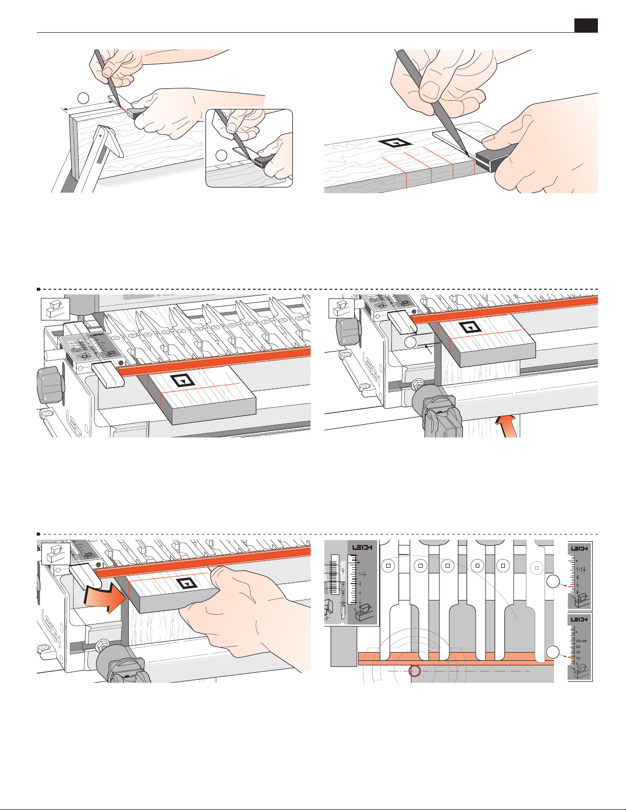
SLIDING DOVETAILS
1
Chapter 16D4R Pro User Guide
2
61
16-7 Marking Out: Do not mark slot positions on board faces;
mark the edges
of both slot boards together for perfectly level
shelves. Mark the narrow test slot board in the same way at several
closely spaced random spots
. This board is used only for setup.
16-9 Mount the test slot board in the rear clamp, markings up.
Dovetail slots are best routed from left to right because the bit's clock-
wise rotation pulls the guidebush against the fence. But when routing
close to both ends of a board, you may need to rout slots from right to
left. See 16-30.
16-8 On the test slot board only, square the marks across the
face.
1
16 -10 Mount a 3⁄4"[20mm] thick (yes, the 3⁄4"[20mm] thick-
ness is important) square-ended board vertically in the front clamp
against the side stop, with the top edge butting the underside of
the test board.
16 -11 Position and clamp the test board so that one of the edge
marks is in line with the outside edge of the vertical board.
1
1
16 -12 With the finger assembly (including the cross cut fence)
on the support brackets in the
7
⁄16"[11mm] . Make sure the finger assembly is level and sitting
to
flush on top of the board. The
HB TAILS mode, set the scale
H
HB TAILS scale was not designed
H
for this operation, but with this setting the routed slot will be close
to centered on the slot line.
Page 70
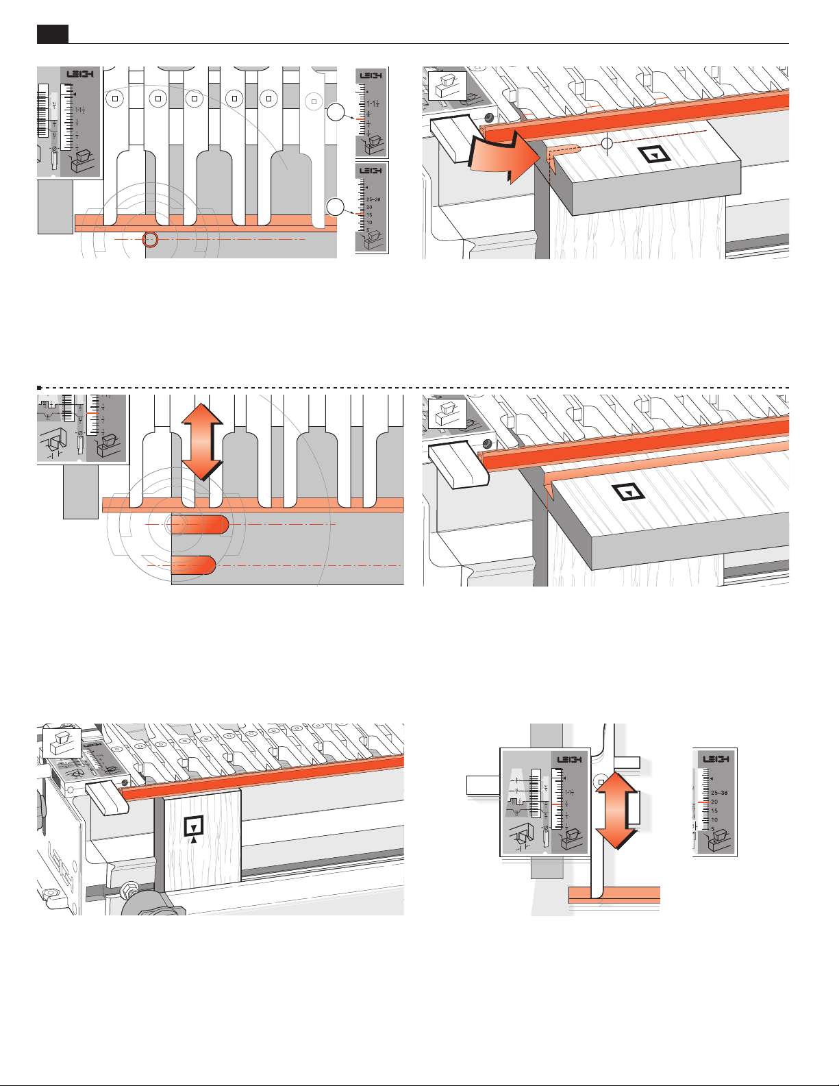
62
Chapter 16 D4R Pro User Guide
2
2
SLIDING DOVETAILS
16 -13 If you use a larger guidebush, for example 5⁄8"[15,9mm]
7
rather than
⁄16"[11,1mm], move the scale in by the difference of
the two guidebush radii.
5
E.g., suggested scale reading for a
11
⁄32"[9mm] .
be
⁄8"[15,9mm] guidebush would
16 -15 Check to see if this short slot is centered on the pencil line.
If not, adjust the finger assembly in or out and retest on the other
lines as necessary until the slot is centered. Lock the finger assembly
in this position and record the setting for future reference.
16 -14 Adjust the bit so the cut depth is about 5⁄16"[8mm]. Rout
from left to right maintaining light inward pressure of the guidebush
on the fence. Rout in only about 1"[25mm] and back out again.
Do not lift the router.
16-16 Now rout sliding dovetail slots in the two main slot boards
with the boards in the horizontal position in the rear clamp, slot
side, that is inside face
The guidefingers must be flush on the board.
i
up.
16 -17 Replace the spacer board in the rear clamp, and with
the finger assembly on the spacer board, mount a test tail board
vertically in the front clamp, flush under the guidefingers. Either
side can face out
j
.
16 -18 The HHB TAILS scale is not designed specifically for
this mode, but it does allow you to make precise adjustments for
tail size and tightness of fit on sliding dovetails.
Page 71
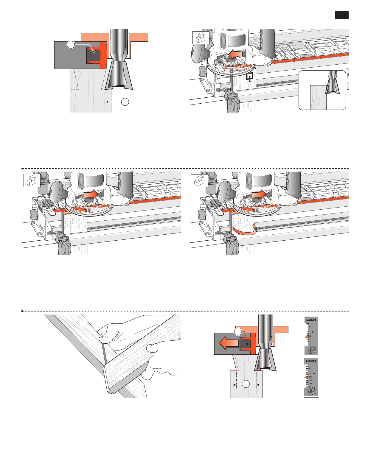
SLIDING DOVETAILS
Chapter 16D4R Pro User Guide
1
2
63
16 -19 Adjust and set the finger assembly so it is clear that the
routed tail will be too large for the slot.
16-21 Finish left to right, with the guidebush touching the
fence.
16-20
Rout one side of the test tail board.
Make one light pass from right to left (climb
routing). Make sure you control it firmly, because it is driven in
this direction by the bit. Only the tip of the bit should be cut‑
ting on the first cut (see inset). This back or climb routing leaves
a very clean shoulder in side grain.
16-22 Turn the test tail board around in the jig and rout the
other side as above.
16-23 Test the joint for fit. The tail should be too big. If it is
too small, adjust the finger assembly outward by at least half the
difference and rout another test tail on the other end of this test
board.
1
2
16-24 If the tail is too big, move the finger assembly toward
the jig by half the amount the tail is too big. Rout the same test board
again; keep adjusting and testing until a good fit.Use trial and error each
time. It doesn’t take long, and you get a good fit. For fine fit adjustment
with the e-Bush see 16-25.
Page 72
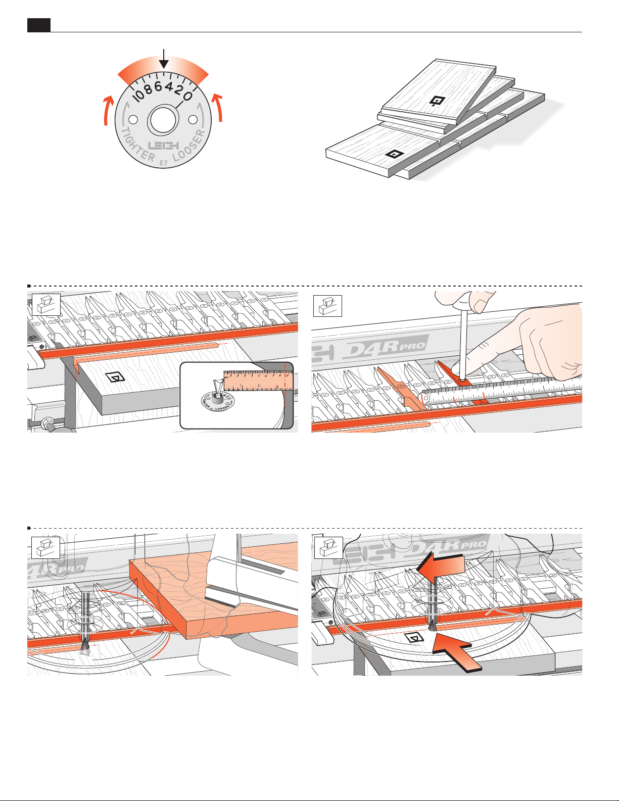
64
8
100
Chapter 16 D4R Pro User Guide
SLIDING DOVETAILS
L
O
O
S
E
R
T
I
G
R
E
T
H
16-25 For fine fit adjustment we use the unique e‑Bush. Note: joint
tightness is only adjusted with tail size, not the socket. To increase the tail
size (tighter joint) rotate the
e‑Bush to a lower number. Each increment
will adjust the joint fit by .001" on the glue line. To decrease the tail
size (looser joint) rotate the
e‑Bush to a higher number. Remember
to rout both sides of the tail board as in 16-21 & 22.
16-26 When the fit is satisfactory, rout one end of a project tail
board and test again. If the fit is good, rout all the other ends.
Note: Variations in board thickness, guidebush diameter, bit depth, angle,
diameter and concentricity, make it impractical to record sliding tail size
settings.
90
80
70
60
50
40
60
50
40
30
20
10
1 2 3 4
30
20
10
100
90
80
70
5
7
6
16-27 Stopped Sliding Dovetails
If a stopped sliding dovetail is called for...
Measure from the outside tip of the dovetail bit to the edge of
the router base.
16-29 Or lightly clamp (with a soft‑jawed clamp) a short board
to the finger assembly to act as a router stop.
16-28 Measure the same distance from where you want the slot
stopped to a position on the finger assembly. Move a guidefinger
to that point and mark the guidefinger with a felt pen as a visual
router stop mark…
16-30
because the bit's clockwise rotation pulls the guidebush
Dovetail slots preferably are routed from left to right
against the fence. However; as when routing close to both ends of a
board, it may be necessary to rout slots from right to left. Bit rota‑
tion will tend to pull the router away from the fence. Feed slower
and maintain constant guidebush pressure against the fence.
■
Page 73
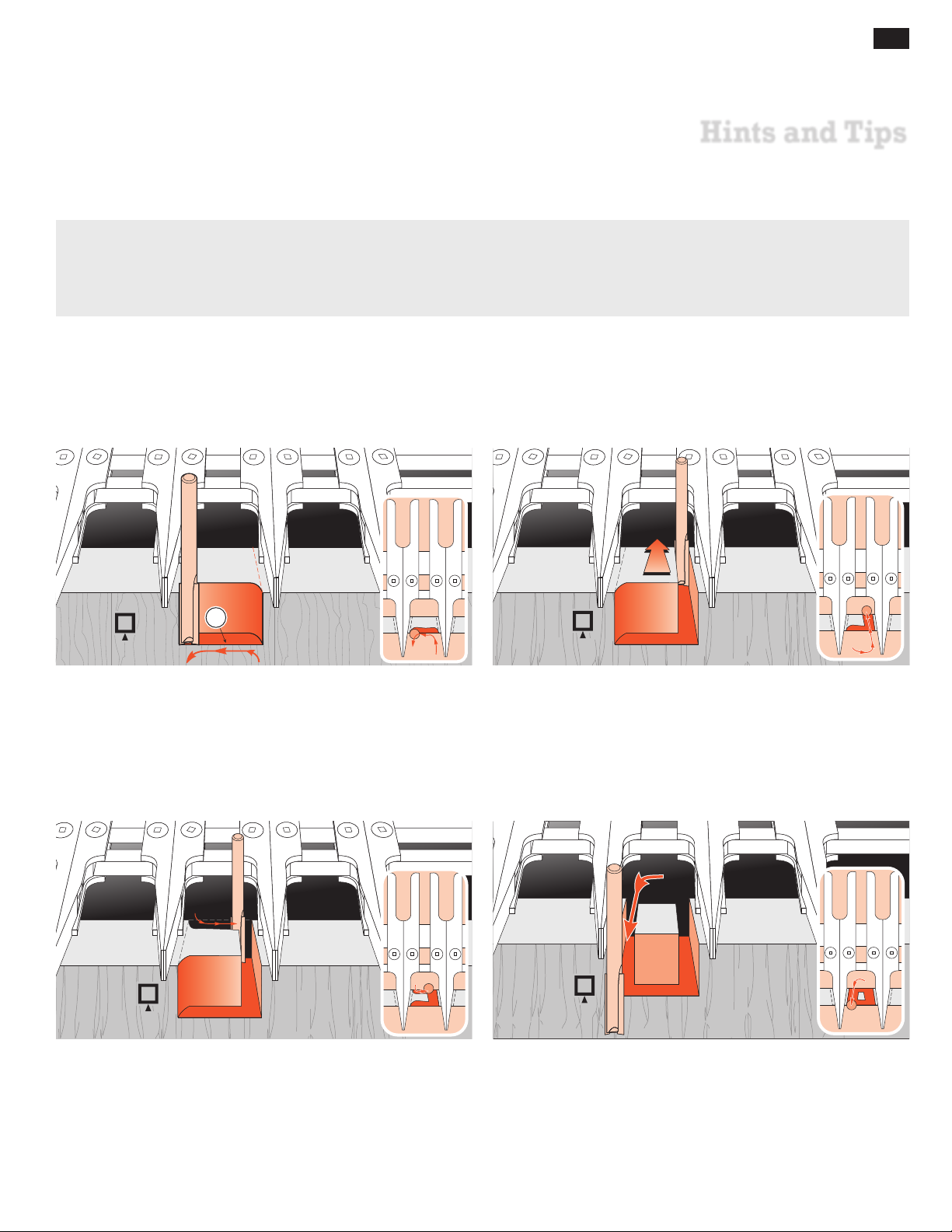
D4R Pro - CHAPTER 17
Hints and Tips
The following pages contain valuable information that will help you get the most from your new Leigh D4R Pro
dovetail jig. Our website contains additional information and technical bulletins that further expand your jig's
capabilities.
Go to: www.leighjigs.com and click on the “Support” tab.
65
1
17-1 Through Dovetail Pins With the straight bit, carefully
climb‑rout from right to left. Make sure you control the router
firmly when climb routing.
Climb routing produces a nice clean shoulder at .
Note: For clarity, the guidebush is not shown in this sequence.
17-3 Climb rout from left to right from the rear of the cut. Take
care to control router.
17-2
17-4
Rout through on the right side.
Rout back through towards you on the left side.
Page 74
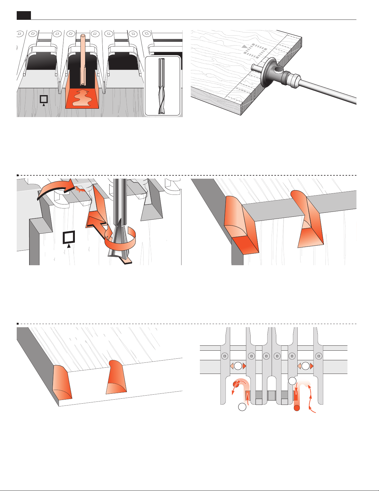
66
Chapter 17 D4R Pro User Guide
HINTS AND TIPS
17-5 Rout away the rest of the waste.
Note: Spiral up‑cut straight bits (inset) generally rout more
smoothly than the two‑flute carbide‑tipped bits. Leigh recom-
mends solid carbide bits.
17-7 Dovetail Tails Tearout With the dovetail bit, most
tearout occurs at the top left exit of the cut.
17-6 Through Dovetail Pins Tearout
To prevent tearout at the back bottom part of a straight cut, scribe
a line with your marking gauge across the back of the pin board
at exactly the depth of cut.
17-8 To help prevent this, back up the cut with the end-grain of
a horizontal board pushed against the back of the workpiece and
held in the rear clamp. This board replaces the spacer board.
17-9 This same scrap piece can remain in place for successive
cuts.
3 3
1
2
17-10 Always rout the right hand half pin socket starting from
behind the board and moving the router outwards , and rout the
left hand half pin socket from the outer face, moving the router
inwards . Position the non-active guide fingers both sides so
that they do not impede this process ➂.
Page 75
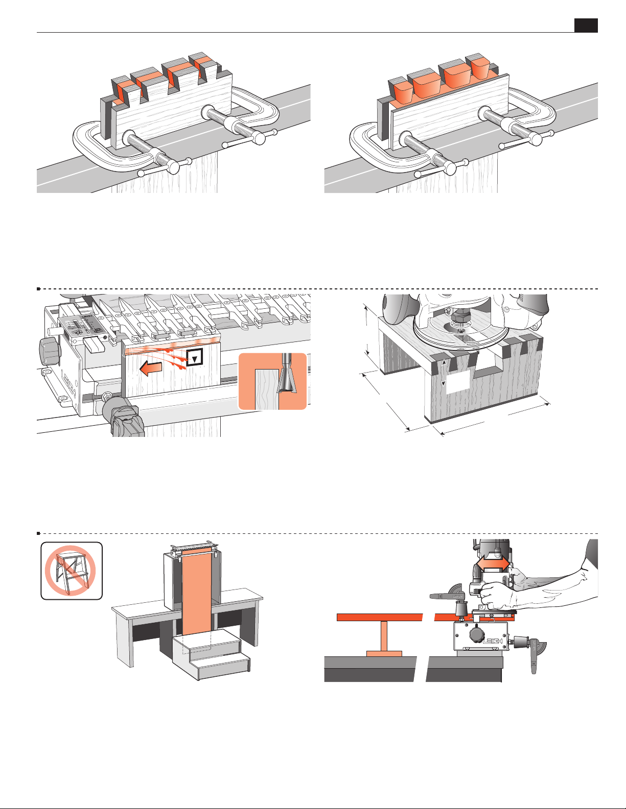
HINTS AND TIPS
Chapter 17D4R Pro User Guide
67
17-11 For particularly vulnerable pieces or that last piece of
exotic wood, the best solution is to clamp horizontal scrap pieces
to front and back of the work piece. Make sure the clamps are
below the bit depth. PLYWOOD material is not suitable for
routing; laminates are very prone to tearout. Figures 17-10 or
17-11 are essential for plywood but do not guarantee success.
17-13
On face cuts, whether using a straight bit or a dove-
tail bit, climb routing or back routing will leave a
clean edge; but great caution must be exercised in controlling
the router’s movement from right to left, as the bit rotation pulls
the router in that direction anyway
17-12 A single scrap piece can be C-clamped on the back of halfblind tails, but make sure you protect the workpiece from the clamp
pads. Note: There is no 100% solution to tearout. It’s not the jig’s
fault, just something that happens when machining, sawing and
even chiseling wood. Important pieces fall off from where you
least want them to.
1
3
/2"
[90mm]
1
"
2
/
1
7"[180mm]
[40mm]
7"[180mm]
17-14 General Hints
Router Stand: Make up a small router stand as illustrated, to mount
the router securely on the bench when not in use.
17-15 For routing long vertical boards it may be necessary to
build a jig stand to mount securely on your bench. Make the stand
and bench height combination sufficient to accept the board length
you have in mind. The jig stand should be bolted securely to the bench.
Make up a stable platform to stand on as in the illustration. Do
not use a set of steps. Steps are not stable enough.
17-16 When placing long horizontal boards in the rear clamp,
make sure the rear end of the board is supported to prevent unnecessary racking of the jig.
Page 76
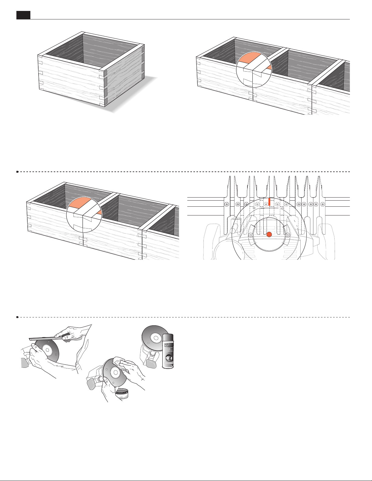
68
Chapter 17 D4R Pro User Guide
HINTS AND TIPS
17-17 More On Symmetry
It doesn’t matter if symmetrical-looking joints on a single box do
not precisely mirror the adjacent corners. No one will ever know
the difference. These joints look perfectly symmetrical on their
own, but...
17-19 Use the asymmetrical mirror image aligning techniques
14-4 to 14-11 for perfectly aligned neighbour joints.
17-18 If a number of these boxes end up side-by- side, e.g. spice
caddys on a kitchen shelf, the slight misalignments of the joints
could be unattractive. So when making boxes or through dovetail
drawers that will be lined up beside each other with the joints
showing...
17-20 Using The Router Mark the router base top edge at
the 12 o’clock position with a felt marker pen. Without wood or
bits, try some dry runs in each jig mode. This will soon get you
used to positioning the guidebush against the correct guide surface
without looking under the router.
Do not rout at face level.
17-21 Some router bases have sharp edges on the outside and
inside corners. A slight chamfer of the edges with a fine file or
sandpaper block will ease router movement on the jig.
An occasional light spray of “Top Cote®” application of soft wax
to the router base makes for smooth, easy router movement on
the jig.
■
Page 77
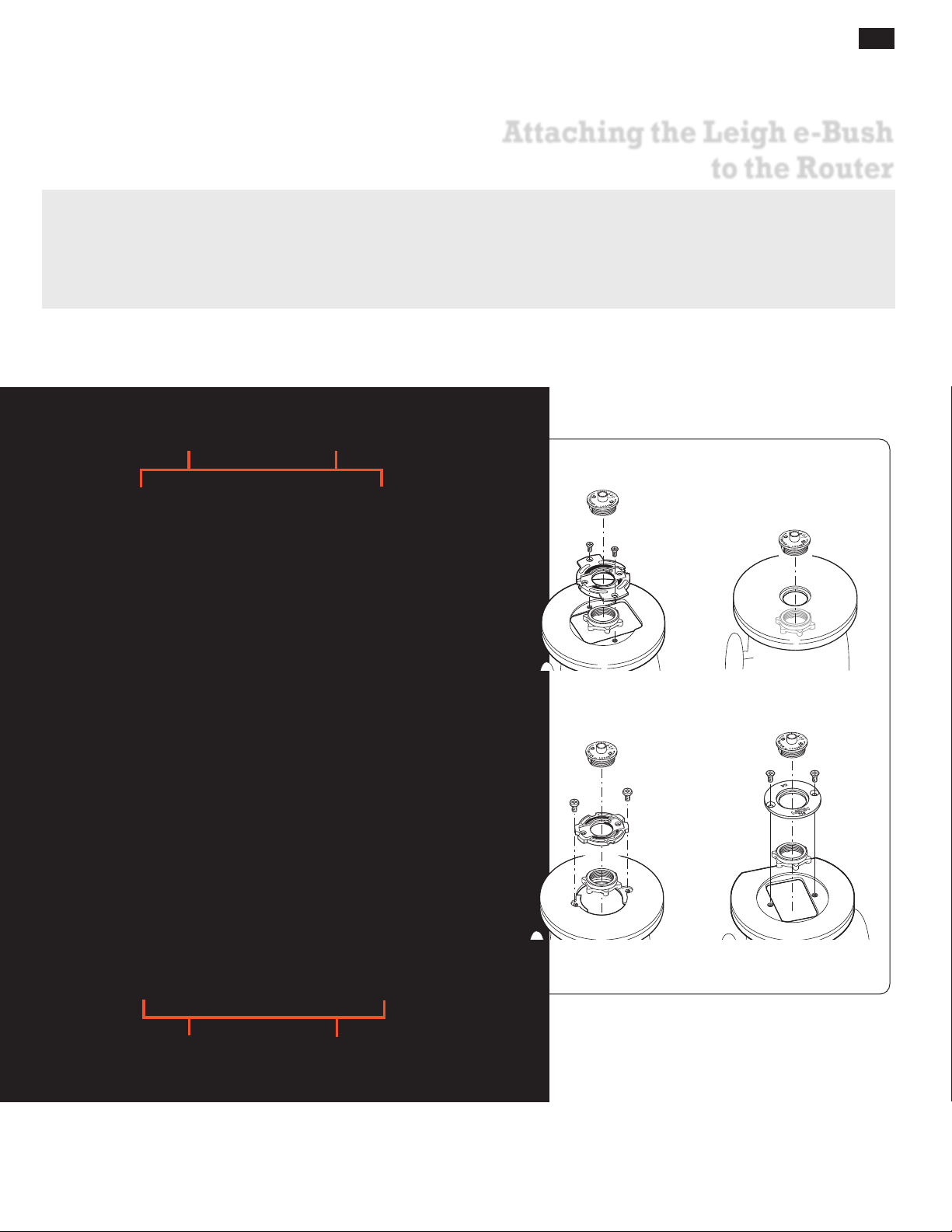
D4R Pro - Appendix I
Attaching the Leigh e-Bush
to the Router
The correct guidebush is the vital link between the router and your Leigh Jig. It precisely steers the router. Where
possible, always use the Leigh system to ensure correct bush length and precise diameter for accurate results.
Leigh offers the adaptors below to fit guidebushes to over one hundred router models new and old, including
Porter Cable, Black & Decker, and DeWalt. Many other makes e.g. Bosch, Fein, Festool, Milwaukee etc., either offer or
include base adaptors. See list of routers in the Template Guide Bushing and Adaptor Selection chart on the next page.
Leigh Template Guide Bushing
and Adaptor System
69
e7
e10
Bosch
RA1100
702R
Bosch
RA1126
(required for
Bosch RA1100)
702
711TP
716TP
706R
721
704R
705R
e-Bush Mounting Variations
e-Bush with
Adaptors 702 & 702R
e-Bushes fit many
routers directly
703
Nut for
e-Bushes
Nut for TP
guidebushes
710
e-Bush with
Adaptor 703
e-Bush with
Adaptor 710
Page 78

70
Appendix I D4R Pro User Guide
ATTACHING THE LEIGH E-BUSH TO THE ROUTER
Template Guide Bushing and Adaptor Selection
Your router may need an adaptor to mount the guide bushing. Find out with this chart.
See www.leighjigs.com for the latest list of routers.
DIRECTIONS
A. Locate name of router maker in
Column 1.
B. Locate router model in Column
2. If your router is not listed visit
leighjigs.com for a complete, upto-date list of routers.
C. Locate adaptor required for your
router in Column 3.
• Order Leigh adaptors (part no’s in
red) in Column 3 from Leigh.
• Order Bosch adaptors RA1100 and
RA1126 in Column 3 from Leigh or
your Bosch dealer.
• Order all other adaptors in
Column 3 from the router
manufacturer’s dealer.
D. Guide bushings in Columns 4 and
5 fit all adaptors listed and may
be ordered if required. Note the
following:
◆
7/16" (e7, 711TP) guide
bushings are supplied with all
Leigh dovetail jigs. Order only if
you require a replacement.
▲ 5/8" (
e10, 716TP) guide
bushings are used with 1/2"
shank router bits on D4R Pro,
D4R, D4, D3 & D1258(R) jigs.
Order only if using 1/2" shank
router bits.
n
MAFELL – Rework adaptor
slightly.
Adaptor Mounting Screws
Screws are included with router.
Guide Bushings
All 8mm shank bits work with the
e7-Bush supplied with your Leigh jig, or
with any 7/16" OD guide bushing that
has a min. barrel length of 1/4". The
optional Leigh e10-Bush or standard
5/8" OD guidebush is used with 1/2"
shank bits. No other guide bushing sizes
can be used.
ROUTER
1
MAKER
BLACK & DECKER
90140, 90088, 90098, 90085, 90150, 90300, 90303, 90305, 91264 Aftermarket base plate required 82855 82854
ROUTERS PRODUCED AFTER mid 2010: 1613AEVS, 1617EVS, 1618EVS, and
BOSCH
CMT 1E 702R e7 or 711TP e10 or 716TP
CRAFTSMAN
(SEARS)
DEWALT
ELU
FEIN RT1800 Supplied w/router e7 or 711TP e10 or 716TP
FESTOOL
FREUD FT700(2), FT2000, FT2200, FT3000 721 e7 or 711TP e10 or 716TP
HITACHI
MAFELL LO65E 702 n e7 or 711TP e10 or 716TP
MAKITA
METABO OF1612, OFE1812 704R e7 or 711TP e10 or 716TP
MILWAUKEE
PERLES OF808 Series, OFE6990 710 e7 or 711TP e10 or 716TP
PORTER CABLE
(ROCKWELL)
RIDGID R2930 704R e7 or 711TP e10 or 716TP
RYOBI
SKIL
TREND T3, T4, T5, T9, T10, T11–UniBase required 710 e7 or 711TP e10 or 716TP
TRITON
WEGOMA OF850 Series 710 e7 or 711TP e10 or 716TP
MR23EVS series, in N.America require Bosch adaptors RA1100 & RA1126.
ROUTERS PRODUCED BEFORE mid 2010: 1613AEVS, 1614EVS, 1617EVS,
1618EVS, 1619EVS POF800ACE, POF1400ACE, POF1100AE, POF1200AE,
GOF1200, GOF900ACE, GOF1300ACE, GOF900CE, GOF2000CE, GMF1400, B1450
M363, MRP090, RP1800, RP1801, RP2301, RP2301FC, 3612C Europe Qk Fit Base 721 e7 or 711TP e10 or 716TP
3600, 3606, 3608, 3612, 3612B, 3612BR, 3612C N. America, 3620, 3621,
All Professional, HD1250, RP400K,7614 Not Required e7 or 711TP e10 or 716TP
SR100, 7AEE, KW780 series, KW 800, KW850 710 e7 or 711TP e10 or 716TP
1600, 1601, 1602, 1603, 1604, 1606, B1350 2 610 906 290 82859 82864
GOF1600CE in Europe requires RA1100 only.
1611, 1611EVS, 1615, 1615EVS, B1550, GOF1600, GOF1700ACE 702 e7 or 711TP e10 or 716TP
MD11 Plunge & Fi xed Base . MD9.5 F ixed Base Not Required e7 or 711TP e10 or 716TP
DW614, DW615, DW621, DW624, DW625, DW626 N. America Only, Supplied w/router e7 or 711TP e10 or 716TP
DW621K & DW626 outside N. America 706R e7 or 711TP e10 or 716TP
DW625 Type 1,2,3,5 outside N. America 702 e7 or 711TP e10 or 716TP
DW624 & DW625 Type 4 outside N.America, DW625EK 702R e7 or 711TP e10 or 716TP
OF1E , OF2E, OF650, OF900E ,OF1000, OF1010E 704R e7 or 711TP e10 or 716TP
OF1400 and OF2200 North America Only Supplied w/router e7 or 711TP e10 or 716TP
RF1100, RF1101, RD1100, RD1101, RP1101 Not Required e7 or 711TP e10 or 716TP
R30, R50, R150, R151, RE155, R500, R501, R502 703 e7 or 711TP e10 or 716TP
R160, R161, R162, R163K, R165, R170,
R175, RE175, R180, R180PL, R181, R185, ERT1150
ROUTER
2
MODEL
6200 720673-00 e7 or 711TP e10 or 716TP
All non-plunge models Aftermarket base plate required
135275070 Plunge See Skil 1823 or 1835
Other plunge models 702 e7 or 711TP e10 or 716TP
DW610, DW616, DW618 Not Required e7 or 711TP e10 or 716TP
DW613, DW615(UK) 710 e7 or 711TP e10 or 716TP
OF15, OF15E, OF97, OF97E 706R e7 or 711TP e10 or 716TP
MOF68, MOF69, MOF96, MOF96E 710 e7 or 711TP e10 or 716TP
MOF131, MOF177 Type 1,2, & 3 702 e7 or 711TP e10 or 716TP
MOF177 Type 4, MOF177EK 702R
2720, 2721, 3328 Not Required e7 or 711TP e10 or 716TP
3303, 3304 EO9600 or 761 270-00 e7 or 711TP e10 or 716TP
3337, 3338, 3339 702 e7 or 711TP e10 or 716TP
OF2000, OF2000E 705R e7 or 711TP e10 or 716TP
OF1400 Outside North America 493566 e7 or 711TP e10 or 716TP
OF2200 Outside North America
TR8, TR12, FM8, M8, M12 Series 325211 OR 703 e7 or 711TP e10 or 716TP
M12VC, KM12SC, KM12VC Not Required e7 or 711TP e10 or 716TP
M12SA2, M12V2 325224 e7 or 711TP e10 or 716TP
RP0900, RP900K
3601B 321 493-1 e7 or 711TP e10 or 716TP
RP0910, RP1110C 706R e7 or 711TP e10 or 716TP
5615, 5616, 5619 49-54-1040 e7 or 711TP e10 or 716TP
5625 49-54-1026 e7 or 711TP e10 or 716TP
5670 Not Required e7 or 711TP e10 or 716TP
All Not Required or Supplied w/router e7 or 711TP e10 or 716TP
R600, R601, RE600, RE601 702 e7 or 711TP e10 or 716TP
1823 or 1835 91803 e7 or 711TP e10 or 716TP
SK1810, 1815, 1820, 1825 RAS140 e7 or 711TP e10 or 716TP
All others Aftermarket base plate required 11592 71021
TRC001 TGA006 or 704R e7 or 711TP e10 or 716TP
JOF001, MOF001, TRA001
ROUTER
3
ADAPTOR
RA1100 Adaptor and RA1126 Quick
Change Adaptor required
RA1100 e7 or 711TP e10 or 716TP
494627 O-Ring may be required
to keep bushing centered
703 e7 or 711TP e10 or 716TP
706R e7 or 711TP e10 or 716TP
Accessory Kit (includes adaptor)
TGA001 or TGA150
7/16"OD
4
BUSHING
e7 or 711TP e10 or 716TP
Order 5-piece set from Sears USA
0925973, or 3-piece set from Sears
e7 or 711TP e10 or 716TP
e7 or 711TP e10 or 716TP
e7 or 711TP e10 or 716TP
5
◆
BUSHING ▲
Canada 0900970704
5/8" OD
Page 79
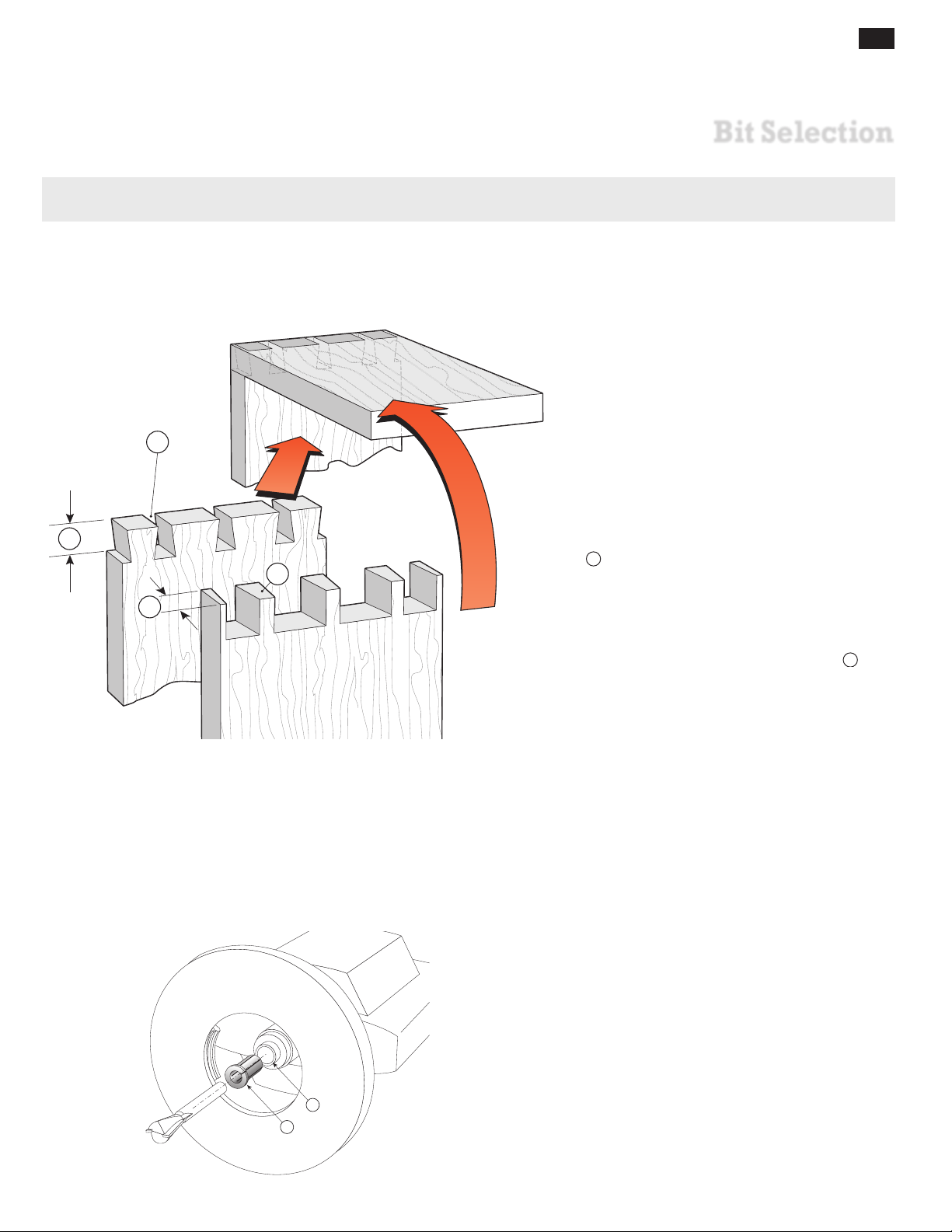
Optional router bits for variably spaced through and half-blind dovetails.
2
1
B
3
Through Dovetails
Bit Selection for Through Dovetails
71
D4R Pro - Appendix II
Bit Selection
8° Dovetail Bit for Tails
The pins
must fit into the sockets . So the dovetail bit’s depth
of cut B must be equal to or a little greater than the
pinboard thickness ➂.
Measure
the pinboard thickness
➂
Select
the dovetail bit with the correct depth of cut B from
the following pages (bits must be 8° for through dovetails).
Straight Bit for Pins
The matching straight bit is listed on the charts with the
dovetail bit.
Guidebush
All 8mm shank through dovetail bits listed in this appendix work with the
Leigh jig, or any ~
e10-Bush or standard
shank bits. No other guidebush sizes can be used for through
dovetails. See page 70.
e7‑Bush (~7⁄16" OD) supplied with your
7
⁄16" OD guidebush. The optional Leigh
5
⁄8" OD guidebush is used with 1⁄2"
Shank Selection
All Leigh Dovetail jigs ship with one through dovetail bit and
1
5
4
one straight bit, with 8mm shanks, plus a
reducer. The reducer
simply slides into the 1⁄2" collet ➄ of
your router and the 8mm shank bit is inserted into the collet
reducer. The collet is tightened as normal. The collet reducer
1
is not required with
⁄2" shank bits. Note: If your router has
an 8mm or larger collet, we highly recommend you use our
1
8mm shank bits instead of
⁄4"[6,35mm] shanks.
⁄2" to 8mm collet
Page 80
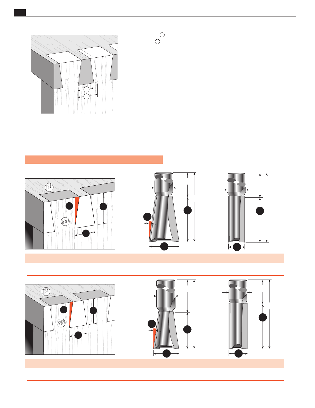
72
C
A
B
D
E
2
1
F
A
B
C
F
A
B
D
E
F
A
B
Appendix II D4R Pro User Guide
Leigh Through Dovetail Bits
Note: Bit and joint drawings are about actual size.
BIT SELECTION
Note that some of the dovetail bits’ depths of cut overlap. For example:
No. 80-8 bit B : 1⁄2"–13⁄16" [12 - 20mm]
No. 90 bit B : 5⁄8"– 1" [16 - 26mm]
5
This means that boards between
⁄8" and 13⁄16"[16 - 20mm] thick can be joined
using either the:
No. 80-8 and 140-8 combination, or the
No. 90 and 160-8 combination.
The two bit combinations will produce slightly different-looking joints because
the No. 80-8 bit can cut a narrower pin socket than the No.90 bit .
Do not attempt to rout dovetails at less than the minimum depth of
cut specified.
100
A B C D E F Guidebush
BITS Overall Diameter Cutting Depth Range Shank Diameters Shank Length Overall Length Angle Diameter
No. 100 13/16" [20,6] 1" to 1-1/4" [26,0 - 32,0] 1/2" [12,7] 1-3/4" [45,0] 3" [76,0] 8° e10 or 5/8"[15,9]
No. 150 7/16" [11,1] up to 1-1/4" [32,0] 1/2" [12,7] 1-3/4" [45,0] 3" [76,0] – e10 or 5/8"[15,9]
D
C
E
90
150
D
C
E
160
B
F
B
A B C D E F Guidebush
Bits Overall Diameter Cutting Depth Range Shank Diameters Shank Length Overall Length Angle Diameter
No. 90 11/16" [17,5] 5/8" to 1" [16,0-26,0] 1/2" [12,7] 1-3/4" [45,0] 2-3/4" [70,0] 8° e10 or 5/8"[15,9]
No. 160 1/2" [12,7] up to 1-1/4" [32,0] 1/2" [12,7] 1-3/4" [45,0] 3" [76,0] – e10 or 5/8"[15,9]
Numbers in brackets are millimeters
A
A
Page 81
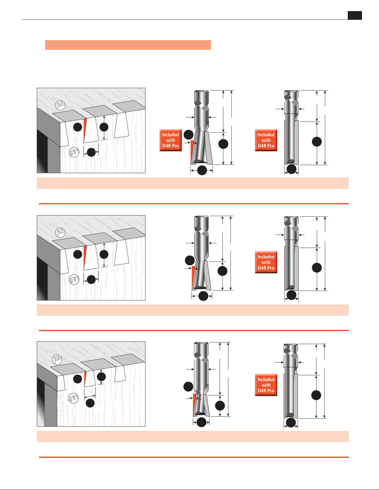
BIT SELECTION
F
A
B
F
A
B
F
A
B
Included
with
D4R Pro
Included
with
D4R Pro
Included
with
D4R Pro
Included
with
D4R Pro
Included
with
D4R Pro
Included
with
D4R Pro
Included
with
D4R Pro
Included
with
D4R Pro
Note: Bit and joint drawings are about actual size.
Appendix IID4R Pro User Guide
73
D
C
E
D
E
C
80-8 140-8
F
B
A
A B C D E F Guidebush
BITS Overall Diameter Cutting Depth Range Shank Diameters Shank Length Overall Length Angle Diameter
No. 80-8 * 1/2" [12,7] 1/2" to 13/16" [13,0-20,6] 8mm (or 1/4") 1-3/4" [45,0] 2-9/16" [65,0] 8° e7 or 7/16"[11,1]
No. 140-8 * 5/16" [7,9] up to 1" [26,0] 8mm (or 1/4") 1-3/4" [45,0] 2-3/4" [70,0] – e7 or 7/16"[11,1]
A
D
C
75-8 140-8
E
B
D
E
C
F
B
B
A
A B C D E F Guidebush
BITS Overall Diameter Cutting Depth Range Shank Diameters Shank Length Overall Length Angle Diameter
No. 75-8 7/16" [11,1] 3/8" to 5/8" [9,5-16,0] 8mm (or 1/4") 1-3/4" [45,0] 2-3/8" [60,0] 8° e7 or 7/16"[11,1]
No. 140-8* 5/16" [7,9] up to 1" [26,0] 8mm (or 1/4") 1-3/4" [45,0] 2-3/4" [70,0] – e7 or 7/16"[11,1]
D
70-8 140-8
C
E
A
D
E
C
F
B
B
A
A B C D E F Guidebush
BITS Overall Diameter Cutting Depth Range Shank Diameters Shank Length Overall Length Angle Diameter
No. 70-8 3/8" [9,5] 1/4" to 1/2" [6,0-13,0] 8mm (or 1/4") 1-3/4" [45,0] 2-1/4" [57,0] 8° e7 or 7/16"[11,1]
No. 140-8* 5/16" [7,9] up to 1" [26,0] 8mm (or 1/4") 1-3/4" [45,0] 2-3/4" [70,0] – e7 or 7/16"[11,1]
Numbers in brackets are millimeters * Bits 80-8, 120-8, and 140-8 come standard with the Leigh D4R Pro
A
Page 82
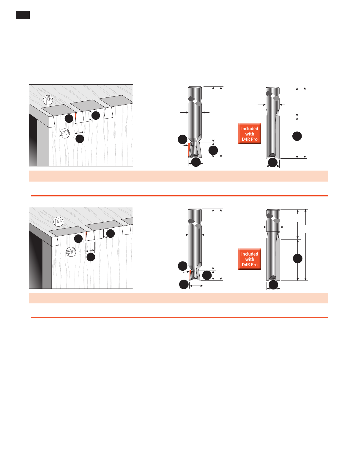
74
F
A
B
F
A
B
Included
with
D4R Pro
Included
with
D4R Pro
Included
with
D4R Pro
Included
with
D4R Pro
Appendix II D4R Pro User Guide
BIT SELECTION
D
C
60-8 140-8
E
F
D
E
C
B
B
A
A B C D E F Guidebush
Bits Overall Diameter Cutting Depth Range Shank Diameters Shank Length Overall Length Angle Diameter
No. 60-8 5/16" [7,9] up to 3/8" [9,5] 8mm (or 1/4") 1-3/4" [45,0] 2-1/8" [54,0] 8° e7 or 7/16"[11,1]
No. 140-8* 5/16" [7,9] up to 1" [26,0] 8mm (or 1/4") 1-3/4" [45,0] 2-3/4" [70,0] – e7 or 7/16"[11,1]
D
C
E
A
D
E
C
50-8 140-8
B
F
B
A
A
A B C D E F Guidebush
Bits Overall Diameter Cutting Depth Range Shank Diameters Shank Length Overall Length Angle Diameter
No. 50-8 1/4" [6,35] up to 1/4" [6,35] 8mm (or 1/4") 1-3/4" [45,0] 2" [50,0] 8° e7 or 7/16"[11,1]
No. 140-8* 5/16" [7,9] up to 1" [26,0] 8mm (or 1/4") 1-3/4" [45,0] 2-3/4" [70,0] – e7 or 7/16"[11,1]
Numbers in brackets are millimeters * Bits 80-8, 120-8, and 140-8 come standard with the Leigh D4R Pro
Page 83
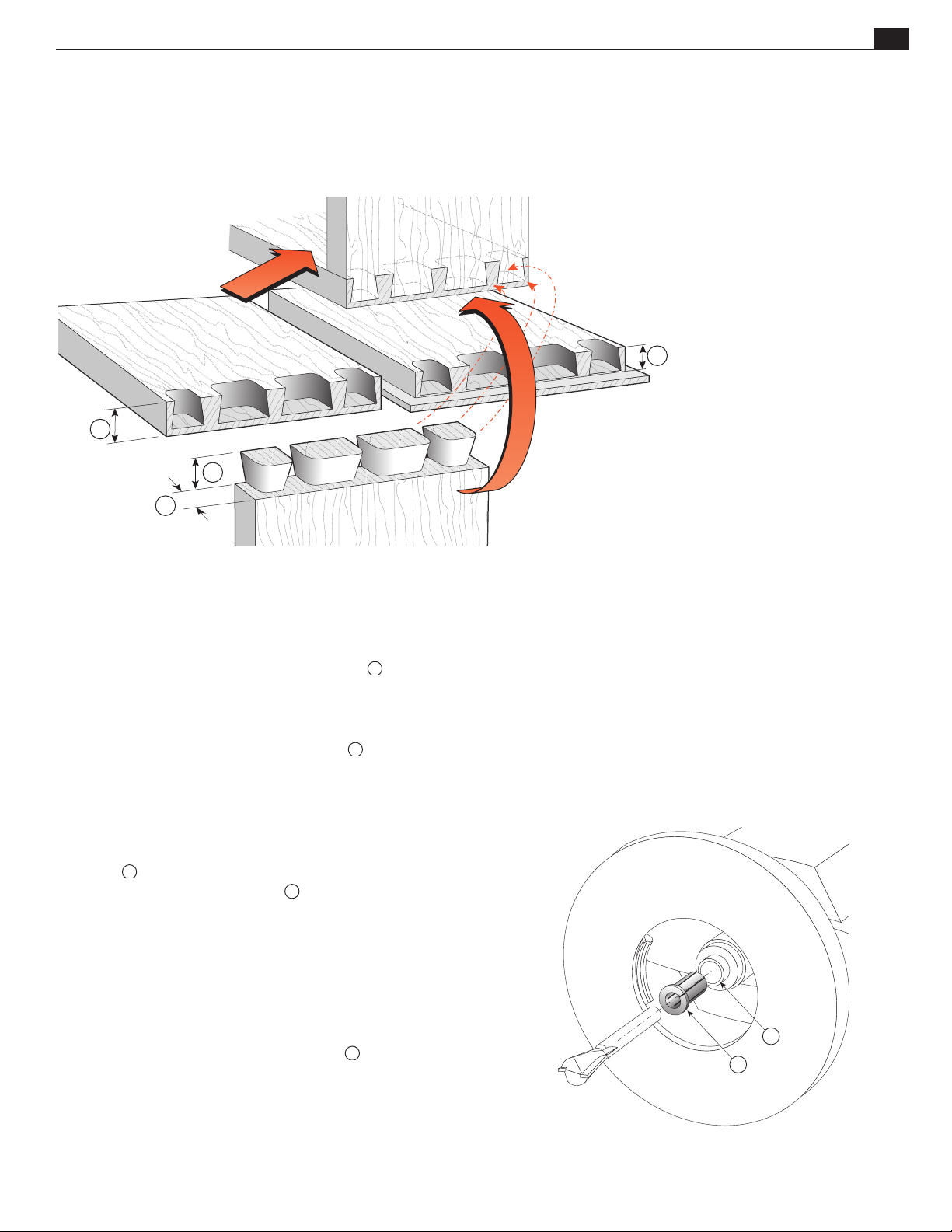
BIT SELECTION
B
B
B
4
5
Half-Blind Dovetails
1
B
Appendix IID4R Pro User Guide
2
75
3
About Bit Selection for Half-Blind Dovetails
Bits:
Both parts of a half-blind dovetail are cut with the same dovetail bit.
Flush Drawers:
The dovetail bit’s working depth of cut B must be less
than the pinboard thickness for flush drawers by at least
1
⁄8"[2mm].
Rabbeted Drawers:
The dovetail bit’s working depth of cut B must be slightly
(about 1⁄16"[1mm]) less than the rabbet depth for rabbeted
drawer fronts.
Drawer Sides (Tailboard):
1
Minimum thickness is
⁄4"[6mm].
Drawer side thickness ➂ does not affect bit selection.
Note:
tails, not the maximum depth.
is the nominal working depth for half‑blind dove‑
must not be varied, except
for minor adjustments for joint fit. See page 37.
Selecting the Bit
Measure
1
Drawer front thickness (minimum
or rabbet depth (minimum ~7⁄16"[11,1mm])
⁄2"[12mm])
Select
A bit with the appropriate depth of cut
from the follow-
ing pages.
Guidebush
All 8mm shank half-blind dovetail bits listed in this appendix work
with the
any ~
e7‑Bush (~7⁄16" OD) supplied with your Leigh jig, or
7
⁄16" OD guidebush. No other guidebush sizes can be used
for half-blind dovetails. See page 70.
Shank Selection
Note: If your router has an 8mm or larger collet, we highly recom‑
1
mend you use our 8mm shank bits instead of
1
⁄2 "[12,7mm] collet you will require our 1⁄2"[12,7mm] to
For a
⁄4"[6,35mm] shanks.
8mm collet reducer No. 172‑8.
Note: This is a collet reducer , not a collet ➄. The reducer does
1
not replace the collet, it slides directly into your
⁄2" collet.
Page 84
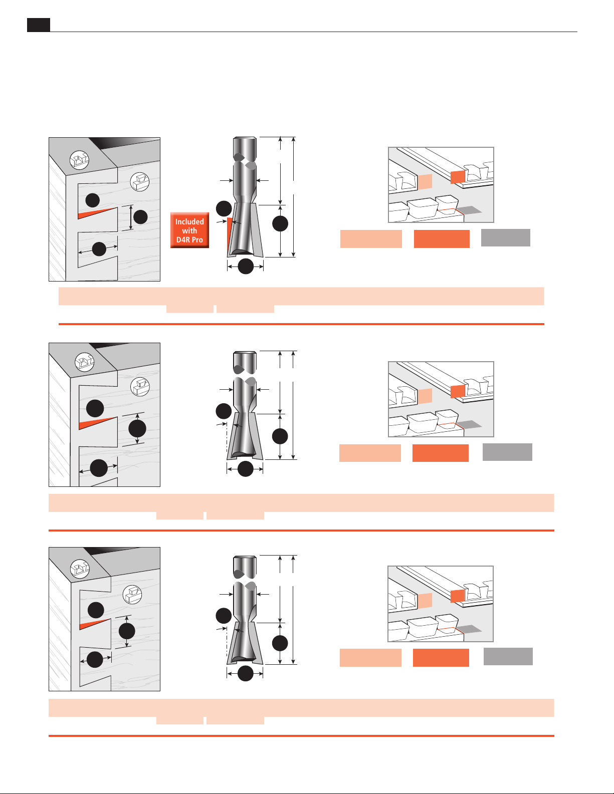
76
E
Included
with
D4R Pro
Included
with
D4R Pro
Appendix II D4R Pro User Guide
Leigh Half-Blind Dovetail Bits
BIT SELECTION
D
C
Bits
No. 80-8*
F
A
B
A
Overall Diameter
1/2" [12,7] ~3/4" [19] ~1/2" [12,7] 8mm (or 1/4") 1-3/4" [44,0] 2-9/16" [65,0] 8˚ e7 or 7/16"[11,1]
80-8
F
A
B
Working Depth
HB Variable HB Single Pass
B
Pinboard
Flush Drawer Front
Min Thickness
7/8"[22mm]
C
Shank DiametersDShank LengthEOverall LengthFAngle
D
E
Pinboard
Rabbeted Drawer Front
Min Rabbet Depth
13/16"[20,5mm]
C
F
101-8
F
A
B
Pinboard
Flush Drawer Front
B
A
Min Thickness
3/4"[19mm]
Pinboard
Rabbeted Drawer Front
Min Rabbet Depth
11/16"[17,5mm]
Tailboard
Drawer Side
Min Thickness
1/4"[6,5mm]
Guidebush
Diameter
Tailboard
Drawer Side
Min Thickness
1/4"[6,5mm]
Bits
No. 101-8
A
Overall Diameter
1/2" [12,7]
HB Variable HB Single Pass
~5/8" [15,9]
B
Working Depth
~7/16" [11,1] 8mm (or 1/4") 1-3/4" [44,0] 2-3/8" [60,0] 10˚ e7 or 7/16"[11,1]
C
Shank DiametersDShank LengthEOverall LengthFAngle
D
E
C
F
112-8
A
F
B
B
A
Bits
No. 112-8
Numbers in brackets are millimeters * Bits 80-8, 120-8, and 140-8 come standard with the Leigh D4R Pro
A
Overall Diameter
HB Variable HB Single Pass
1/2" [12,7] ~1/2" [12,7] ~3/8" [9,5] 8mm (or 1/4") 1-3/4" [44,0] 2-21/64" [59,0] 12˚ e7 or 7/16"[11,1]
B
Working Depth
C
Shank DiametersDShank LengthEOverall LengthFAngle
Pinboard
Flush Drawer Front
Min Thickness
5/8"[16mm]
Pinboard
Rabbeted Drawer Front
Min Rabbet Depth
9/16"[14,5mm]
Guidebush
Diameter
Tailboard
Drawer Side
Min Thickness
1/4"[6,5mm]
Guidebush
Diameter
Page 85
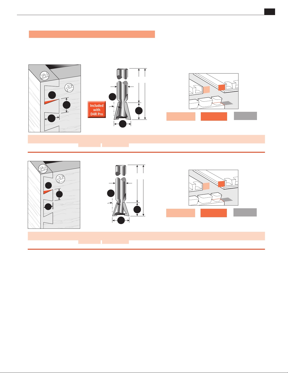
BIT SELECTION
Included
with
D4R Pro
Included
with
D4R Pro
Note: Bit and joint drawings are about actual size.
Appendix IID4R Pro User Guide
D
E
77
C
Bits
No. 120-8*
F
120-8
F
A
B
B
A
A
Overall Diameter
HB Variable HB Single Pass
1/2" [12,7] ~7/16" [11,0] ~9/32" [7,1] 8mm (or 1/4") 1-3/4" [44,0] 2-1/4" [57,0] 14˚ e7 or 7/16"[11,1]
B
Working Depth
C
Shank DiametersDShank LengthEOverall LengthFAngle
D
E
Pinboard
Flush Drawer Front
Min Thickness
9/16"[14,5mm]
Pinboard
Rabbeted Drawer Front
Min Rabbet Depth
1/2"[12,7mm]
Min Thickness
1/4"[6,5mm]
Guidebush
C
F
A
128-8
B
F
B
A
Pinboard
Flush Drawer Front
Min Thickness
1/2"[12,7mm]
Pinboard
Rabbeted Drawer Front
Min Rabbet Depth
7/16"[11mm]
Tailboard
Drawer Side
Min Thickness
1/4"[6,5mm]
Tailboard
Drawer Side
Diameter
A
Bits
No. 128-8
Numbers in brackets are millimeters * Bits 80-8, 120-8, and 140-8 come standard with the Leigh D4R Pro
Overall Diameter
HB Variable HB Single Pass
1/2" [12,7] ~3/8" [9,5] ~7/32" [5,5] 8mm (or 1/4") 1-3/4" [44,0] 2-1/8" [54,0] 18˚ e7 or 7/16"[11,1]
B
Working Depth
C
Shank DiametersDShank LengthEOverall LengthFAngle
Guidebush
Diameter
Page 86

78
Appendix II D4R Pro User Guide
BIT SELECTION
Page 87

D4R Pro - Appendix III
Jig Parts
See parts list and drawing on the following pages.
Order parts directly from Leigh by calling toll-free 800-663-8932 — but first have your jig information ready.
Please quote the jig model, serial number, part number, part description and quantity required.
79
Page 88

80
Appendix III D4R Pro User Guide
How to Order Parts
Order directly from Leigh by calling toll free 800-663-8932 —but first have your
jig information ready. You’ll need the jig model, serial number, part number, part
description and quantity required.
mode to determine left hand and right hand scales.
PART DESCRIPTION PART No. QUANTITY
User Guide D4R Pro (English–Inch/Metric) 560 1
Instructional DVD (English - inch only) 26 1
Dovetail Bit, 8mm shank 80-8 1
Dovetail Bit, 8mm shank 120-8 1
Straight Bit, 8mm shank 140-8 1
1/2" to 8mm collet reducer 172-8 1
Body Extrusion 212 1
R.H. End-Housing 232 1
L.H. End-Housing 242 1
End-Housing Screws 260R 8
Clamp Bar T-Bolts 271 4
Flat Washers for Clamp Bolts 283 4
Accessory Attachment Square Nuts 284 2
Accessory attachment screw 287 1
Clamp Bar Bolt Nuts 300 4
Clamp Bar Springs 311 4
Front Clamp Bar (complete with End Plugs 7115) 332R 1
Rear Clamp Bar (complete with End Plugs 7115) and Leigh decal 335 1
R.H. Inch Scale Assembly, complete (R.H. in H.B. Tail Mode) 392 1
or R.H. Metric Scale Assembly, complete (R.H. in H.B. Tail Mode) 392M 1
L.H. Inch Scale Assembly, complete (L.H. in H.B. Tail Mode) 394 1
or L.H. Metric Scale Assembly, complete (L.H. in H.B. Tail Mode) 394M 1
Cross Cut Fence 432 1
Bridge Piece extrusion 433 2
H.B. Pin Guide Rail, 1/4" x 1/4" 441B 1
Finger Guide Rail, 1/4" x 3/4" 451B 1
R.H. Finger complete with Wedge, Washer, Nut and Screw 463 13
L.H. Finger complete with Wedge, Washer, Nut and Screw 473 13
Finger Wedge 7220 26
Finger Nut (Threaded) 7210 26
Finger Washer 7215 26
Finger Lock Screw 7225R 26
Leigh Assembly Wrench/Gauge 540 1
Finger Adjusting Screwdriver 550 1
R.H Support Bracket 5260 1
L.H. Support Bracket 5270 1
Cam-Action Speed-Clamps complete with Step Washers 802 801 4
Speed-Clamp Step Washers 802 4
Scale Lock Set Screws 3110R 2
5/64" Hex Key (2mm may also work) 3156 1
1/4"-20 Hex nuts, jig hold-down 6030 4
1/4"-20x1 Flat head machine screws, jig hold-down 6060 4
Support Bracket Knobs 7025 2
Clamp Bar End Plug 7115 4
E7-Bush Oval Guide Bush & Nut E7-Bush 1
Pin Wrench 730V 1
Nylon Stop Rod 8624 1
D4R Pro Dovetail Spacer 570 1
D4R Pro Box Joint Spacer 580 1
JIG PARTS
Note: Place the finger assembly in half-blind
Page 89
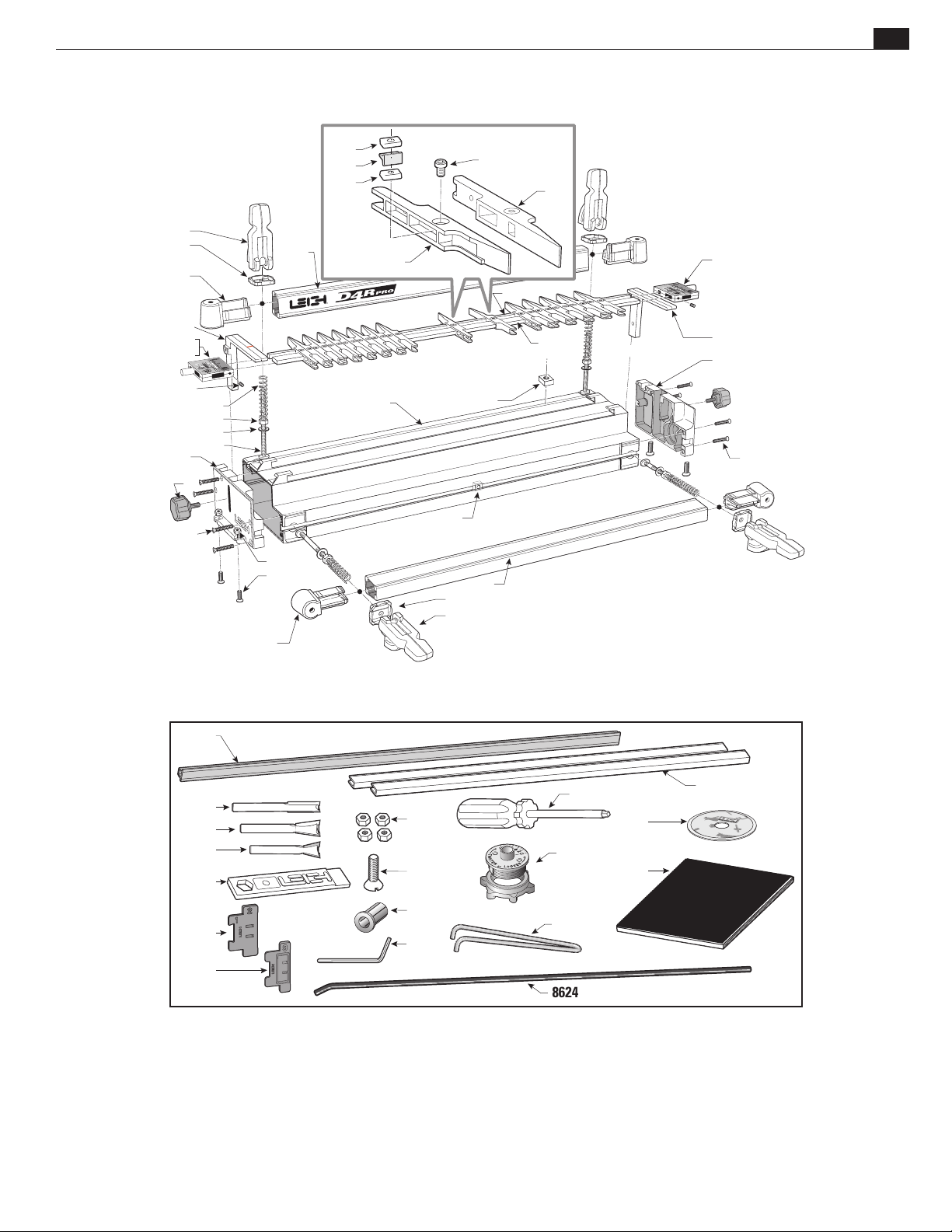
JIG PARTS
Appendix IIID4R Pro User Guide
81
801
802
7115
5270
394
394M
3110R
242
7025
260R
311
300
283
271
335
6030
6060
7215
7220
7210
212
463
284
802
801
7225R
284
332R
441B
473
451B
392
392M
5260
232
260R
432
140-8
80-8
120-8
540
570
580
7115
6030
287
172-8
3156
e-7
730V
8624
550
433
26
560
Page 90

82
Appendix III D4R Pro User Guide
JIG PARTS
Page 91

83
D4R Pro - Appendix IV
Customer Support
Our Commitment to You Leigh Industries takes pride in its commitment to providing excellence in customer service and
support. This user guide is designed to provide you with the answers to any questions you have. However, if you require
assistance, please feel free to contact our technical support staff or a distributor listed below.
Manufacturer: Canada/USA
NOTE:
LEIGH INDUSTRIES LTD. (est. 1981)
P.O. Box 357
1615 Industrial Ave.
Port Coquitlam, B.C.
Canada, V3C 4K6
Distributors
Toll Free: 800-663-8932
Phone: 604-464-2700
Fax: 604 464-7404
Customer Service: [email protected]
Tech Support: [email protected]
Web Site: www.leighjigs.com
Email can be useful, but technical queries usually
raise queries from us. A phone call is the quickest and most
convenient way to get queries answered; either directly
to Leigh (toll-free in North America) or to your national
distributor.
–Thanks!
AUSTRALIA & NEW ZEALAND
Carba-Tec Pty. ltd.
128 Ingleston Rd., Wakerley, Qld., 4154
Australia
Tel: (07) 3390 5888
Fax: (07) 3890 5280
Order: 180 658 111
Email: [email protected]
Web: www.carbatec.com.au
CHINA
Harvey Industries Co., Ltd.
68-10 Suyuan Avenue
Jiangning District Nanjing 211100, China
Tel: (0)86 5792 8869 / 5792 8021
Fax: (0)86 5792 8826
Email: [email protected]
Website: www.harveyworks.cn
FRANCE
Ets Bordet
23 Rue Traversiere
93556 Montreuil Cedex, France
Tel: 01 48 58 28 39
Fax: 01 48 58 48 58
Email: [email protected]
Web: www.bordet.fr/pages/
GERMANY, AUSTRIA & SWITZERLAND
Hacker GMBH
Holzbearbeitungsmaschinen
Traberhofstraße 103 D-83026 Rosenheim,
Deutschland
Tel: 08031 269650
Fax: 08031 68221
Email: [email protected]
Web: www.leigh.de
ITALY
Ferrari Macchine Legno SRL
Via Gallarata 74/76/78
20019 Settimo M.se (MI) Italy
Tel: 39 02 335 010 95
Fax: 39 02 335 005 27
Email: [email protected]
Web: www.ferrarimacchine.com
JAPAN
Off Corporation Inc.
323-1 Yanbara, Shimizu-ku, Shizuoka-shi
Shizuoka-ken, Japan 424-0002
Tel: 81-054-367-6511
Fax: 81-054-367-6515
Email: [email protected]
Web: www.off.co.jp
KOREA
Leigh Korea
1st Floor, Yongyu Building, 25-3,
Neung Pyung-Ri, Opo-Eup, Kwangju-Si,
Kyunggi-do, Korea
Tel: 82 (0) 70-8252-0988
Fax: 82 (0) 31-765-5602
Email: [email protected]
Web: www.htools.co.kr
RUSSIA
Unicom Ltd.
Nikitskij Boulevard 12
Moscow, 119019, Russia
Tel: 7 (495) 690 0454
Email: [email protected] (Russia)
Email: [email protected] (Ukraine)
Web: www.leighjigs.ru (Russia)
Web: www.leighjigs.ua (Ukraine)
SOUTH AFRICA
Hardware Centre Group
Post: PO Box 4059, 2125
Randburg, South Africa
Tel: (011) 791-0844/46
Fax: (011) 791-0850
Email: [email protected]
Web: www.hardwarecentre.co.za
SWEDEN
Toolbox Sweden AB
Bruksgatan 3, S-597 30
Atvidaberg, Sweden
Tel: 46 120 854 50
Fax: 46 120 854 69
Email: [email protected]
Web: www.toolbox.se
UNITED KINGDOM & IRELAND
BriMarc Tools & Machinery
Unit 10, Weycroft Avenue
Axminster, Devon
EX13 5PH England
Tel: 0333 240 6967
Fax: 0333 240 6976
Email: [email protected]
Web: www.brimarc.com
© 2008 Leigh Industries Ltd. All rights reserved.
No part of this publication may be reproduced, stored
in a retrieval system, or transmitted in any form or
by any means, electronic, mechanical, recording, or
otherwise, without the prior written permission of
Leigh Industries Ltd. Updated 10/2014
Page 92

Leigh Router Joinery Jigs
Joining Tradition with Today
Printed in Canad a
PRINTED IN CANADA
 Loading...