

Page 1
See Page 65 for Customer Support
1-800-663-8932
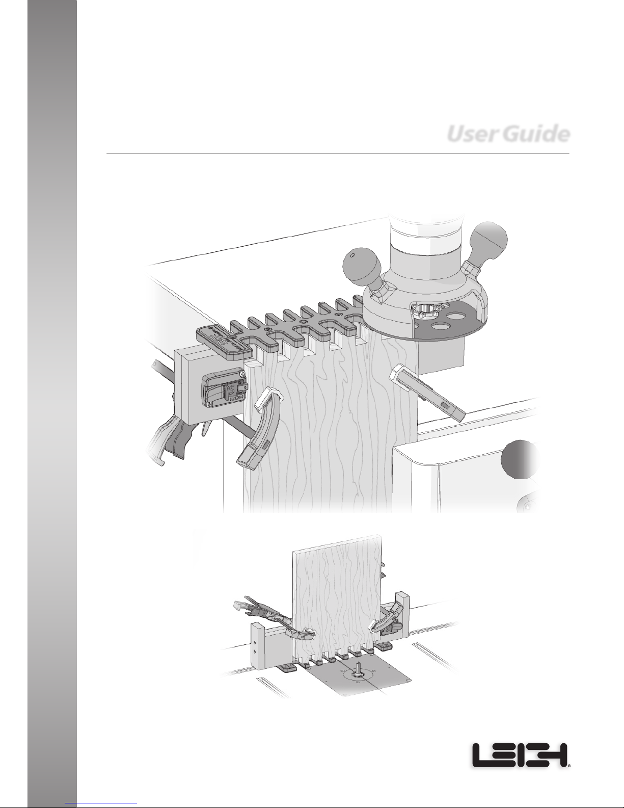
User Guide
Leigh Router Joinery Jigs
Router Table
Workbench
Leigh Box Joint
& Beehive Jig
Model B975
For WorkBench or Router Table Use
Page 2

B975 User Guide
2
Chapter 1 Introduction 5
Jig Parts 5
Bit Specifications 7
Symbols for Board Position 8
Clamping 8
Chapter 2 Safety 9
Chapter 3 The Leigh e10 eBush 11
Chapter 4 Mounting & Assembly 15
Chapter 5 Routing Box Joints 25
Chapter 6 Routing Wider Boards 37
Chapter 7 Router Table Operation 47
Chapter 8 Guide Bushing Adapter Selection 63
Chapter 9 Customer Support 65
Contents
5 Year Warranty
Leigh stands behind its products with a 5 year limited warranty. See the
complete warranty in Chapter 9, Customer Support.
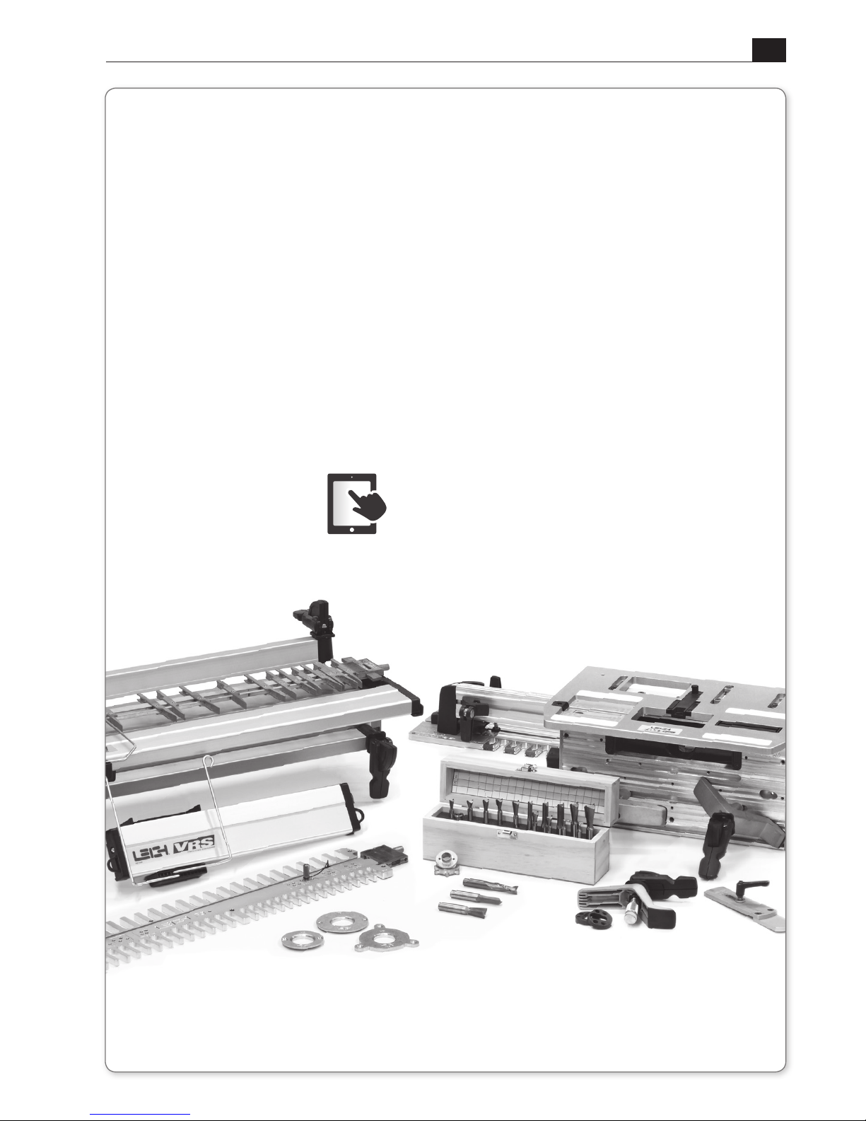
Your New Leigh Box Joint & Beehive Jig, Model B975
The Leigh Box Joint & Beehive Jig, Model B975, is a simple, easy-to-use tool for making
1/2" and 3/4" box joints on boards up to 13/16"[20.6mm] thick, and from 1-1/2"[38mm]
to 17-13/16"[453mm] wide. Not by accident, the full 9-11/16"[246mm] width of the jig
is the standard height of a typical beehive super, used in North America.
Customer Support
If you have any questions that are not answered in this user guide, please call Leigh Customer
Support: 1-800-663-8932 in North America or email: [email protected]. For support
contacts in your country of purchase, see Customer Support at the end of this Guide.
Leigh user guides are updated as required. A downloadable pdf of the latest version can be
found on the Support page at leighjigs.com.
Reminder: If at first you don’t succeed, read the instructions!
Page 3
B975 User Guide
3
*You must be at least 21 years of age to enter. Employees of Leigh Industries Ltd. and their families are ineligible to enter or win.
This offer void where prohibited by law. Customer must complete a short online questionnaire. One winner will be drawn every
two months. Winners will be notified by email and by phone. Leigh product is only available directly from Leigh or its international
distributor in the region of the winner. No cash value. Value is in the currency of the country of winner equal to $300.00 USD based
on currency exchange at the time of the draw. Complete details available at www.leighjigs.com.
Register your Leigh B975
Register Now for Your Chance to
Privacy Policy Leigh will NEVER rent, sell or distribute your information.
• Be the first to learn new ways to use your jig
• Learn about updates to your jig
• Save $$ with Special Offers
• Find out about new product launches
Here’s Why!
Win
$
300 of Leigh Products
*
Go to leighjigs.com
Click on Customer Service
Click on Registration
Page 4

B975 User Guide
4
This page is left blank intentionally.
Page 5
5
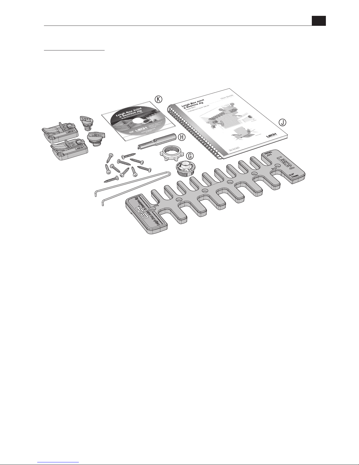
*Leigh e10 Elliptical Guide Bushing: U.S. Patent no. 9,375,860 UK Patent no. GB2443974
Note: PDF of User Guide included on DVD
If any parts are missing from your jig, please notify your supplier
or Leigh immediately. See Chapter 9, Customer Support.
PART DESCRIPTION PART NO. QUANTITY
A
Jig Template with Decal 313503 1
Bag 1
B
Side Stop Assembly, 1/2" 313530 1
C
Side Stop Assembly, 3/4" 313535 1
D
Step-over Cam with O-ring, 1/2" 313550 1
E
Step-over Cam with O-ring, 3/4" 313555 1
Bag 2
F
Pan Head Wood Screws, No.8 x 1" 313585 10
G
Guide Bushing, e10* eBush e10 1
H
Straight Bit, 1/2" 160 1
I
Pin Wrench 730V 1
Bag 3
J
Fully Illustrated User Guide 313565 1
K
Instructional DVD 313570 1
What’s Included
B975 User Guide
CHAPTER 1
Introduction
A
B
C
D
E
F
G
H
K
I
J
Page 6
B975 User Guide
Chapter 1 Introduction
6
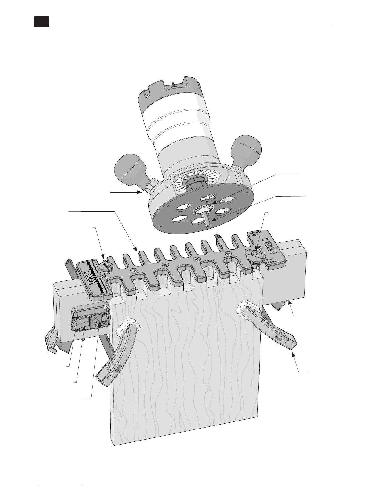
1/2" Bit
e10 eBush
Clamps
(User Supplied)
Step-over Cam 3/4"
Step-over Cam 1/2"
MDF Beam
(User Made)
Side Stop
Template
Router (User Supplied)
Leigh Box Joint & Beehive Jig
Thumb Lock
Pin Board and
Socket Board Stops
Page 7
B975 User Guide
Chapter 1 Introduction
7
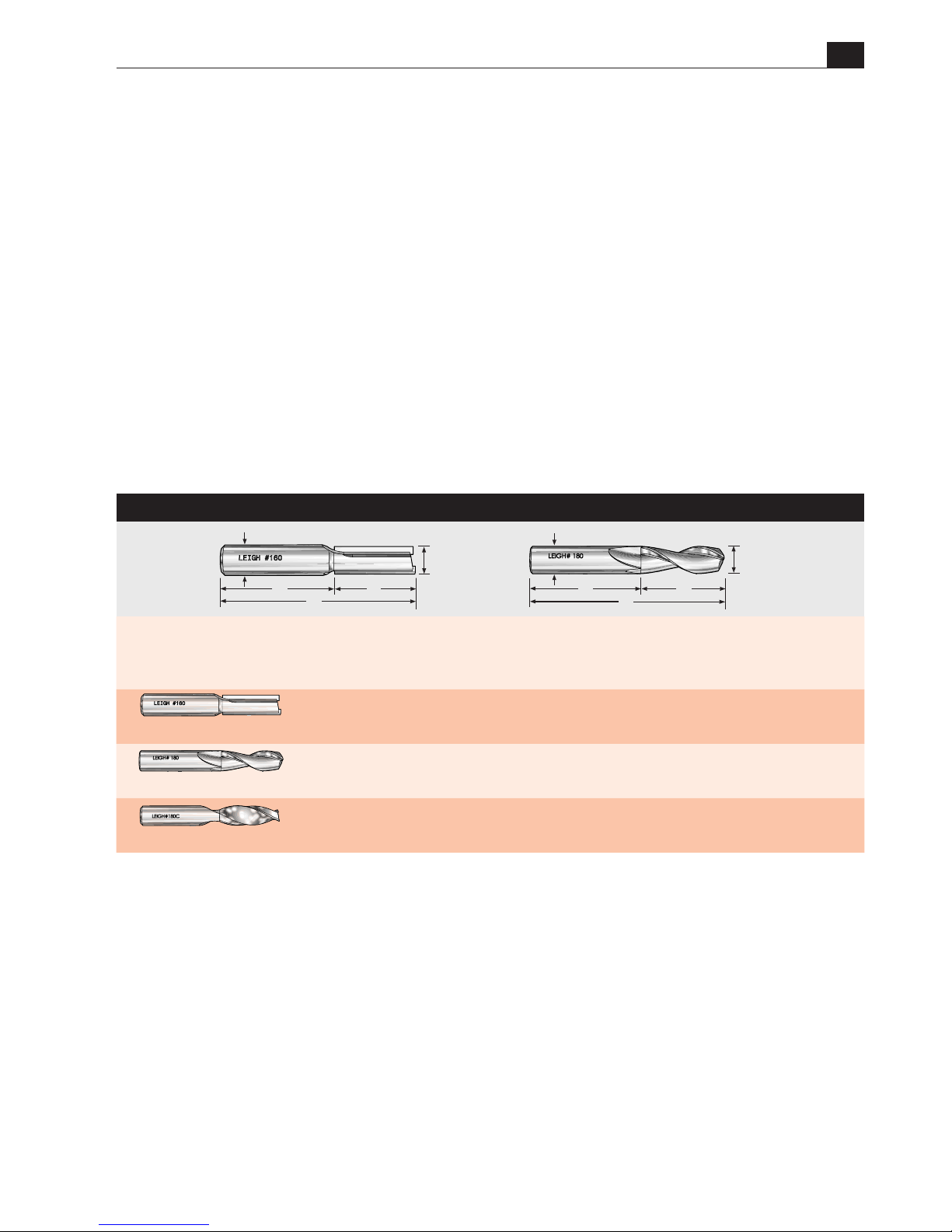
Bit Specifications
Leigh Bits
A
Bit
Diameter
B
Max.
Cutting
Depth
C
Shank
Diameter
D
Shank
Length
E
Overall
Length
Use with Collet/
Collet reducer
Use with
eBush
160
*
Carbide tipped
1/2" 1-1/4" 1/2" 1-7/8" 3-1/8"
1/2"
Collet
e10
180
**
High Speed Steel
1/2" 1-3/4" 1/2" 1-3/4" 3-1/2"
1/2"
Collet
e10
180C
**
Solid Carbide
1/2" 1-5/8" 1/2" 1-7/8" 3-1/2"
1/2"
Collet
e10
Bit Specifications
There is only one bit size used with the Box Joint & Beehive Jig. Your new jig is shipped
with a 1/2", 2 flute, carbide tipped straight bit. You may also use a 1/2" spiral up cut bit
in high speed steel or solid carbide.
E
* 160 bit comes with the Beehive Box Joint Jig
** Optional spiral up cut bits rout cleaner and faster, leaving a smoother finish
A
C
B
D
E
A
C
Units of Measure
IMPORTANT! INCHES AND MILLIMETERS
Text and illustrations in this English language user guide indicate dimensions in both
inches and millimeters, where applicable, with “inches” first, followed by “millimeters” in
square brackets, i.e. 1/2" x 2"[12.7mm x 51mm].
Don’t be concerned that the inch/millimeter equivalents are not mathematically
“correct”.
BD
Page 8
B975 User Guide
Chapter 1 Introduction
8
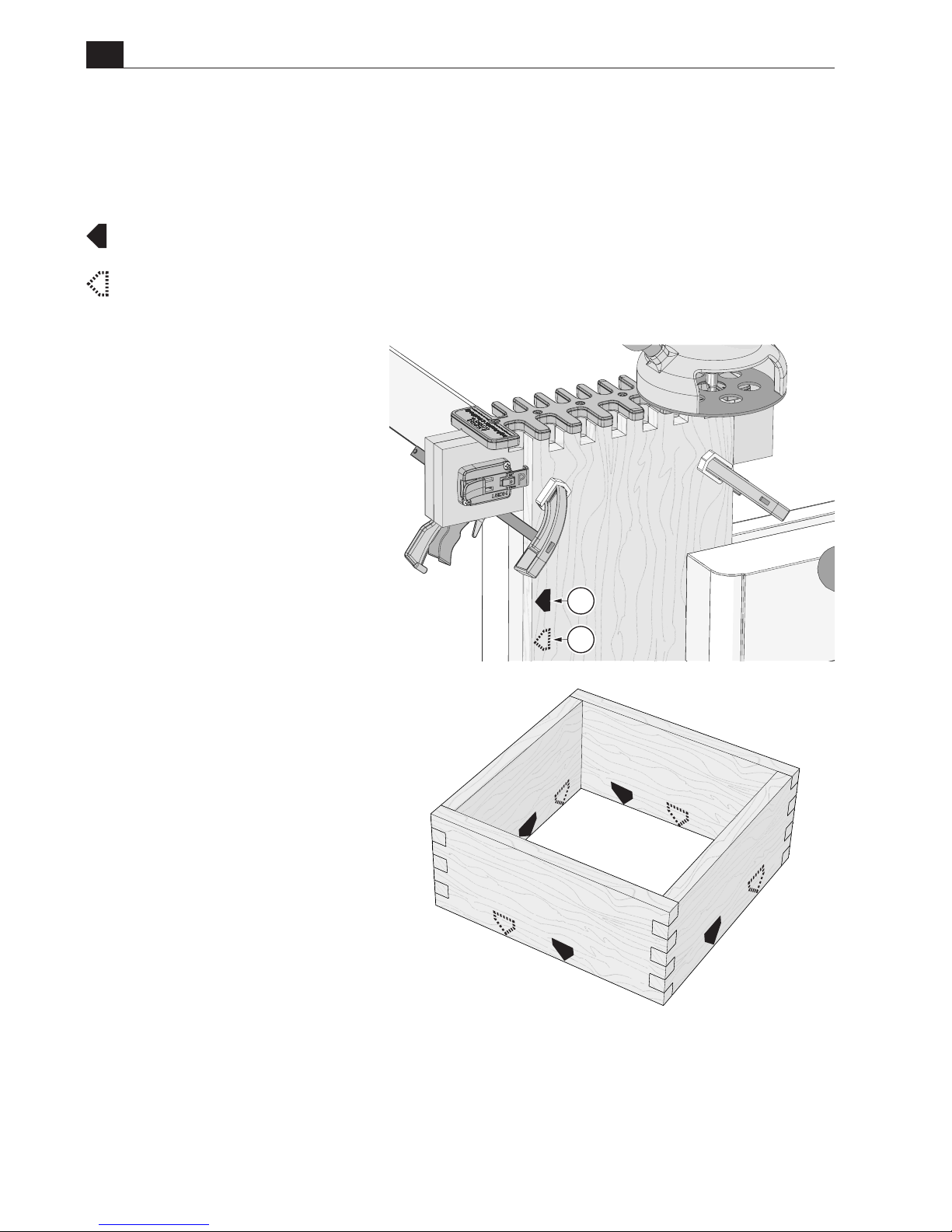
Symbols for Board Position
The following symbols are used throughout this user guide. They indicate which edge of
the board goes against the side stop.
This board edge against the side stop.
This board edge against the side stop (on other side of the board hidden from view).
Box Assembly
Assemble the box, keeping the
marked edges of the boards together
as shown.
Clamping
Note: Before mounting and
routing the boards, you
should mark them with the
appropriate symbols.
With
box joints, the same board
edge
A
always goes against the
side stop. Boards are clamped
against the beam both face in and
face out for alternate end cuts.
A
A
Page 9
9
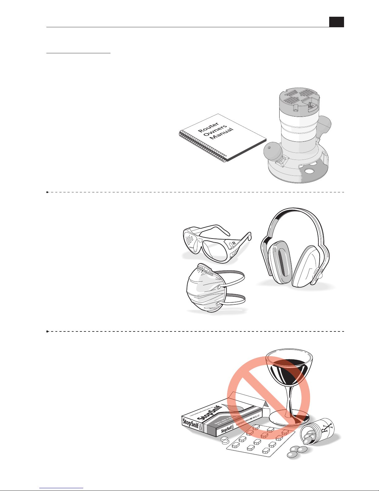
Always wear:
• approved safety glasses;
• a face mask to protect yourself
from harmful dust;
• hearing protection.
Safety is not optional. Read and
follow the recommendations here.
Never drink alcohol or
take medications that can cause
drowsiness while operating a router.
Read the owner’s manual that
came with your router and router
table. It is essential to understand
all manufacturer’s instructions
completely.
B975 User Guide
CHAPTER 2
Safety
Page 10
10
B975 User Guide
Chapter 2 Safety
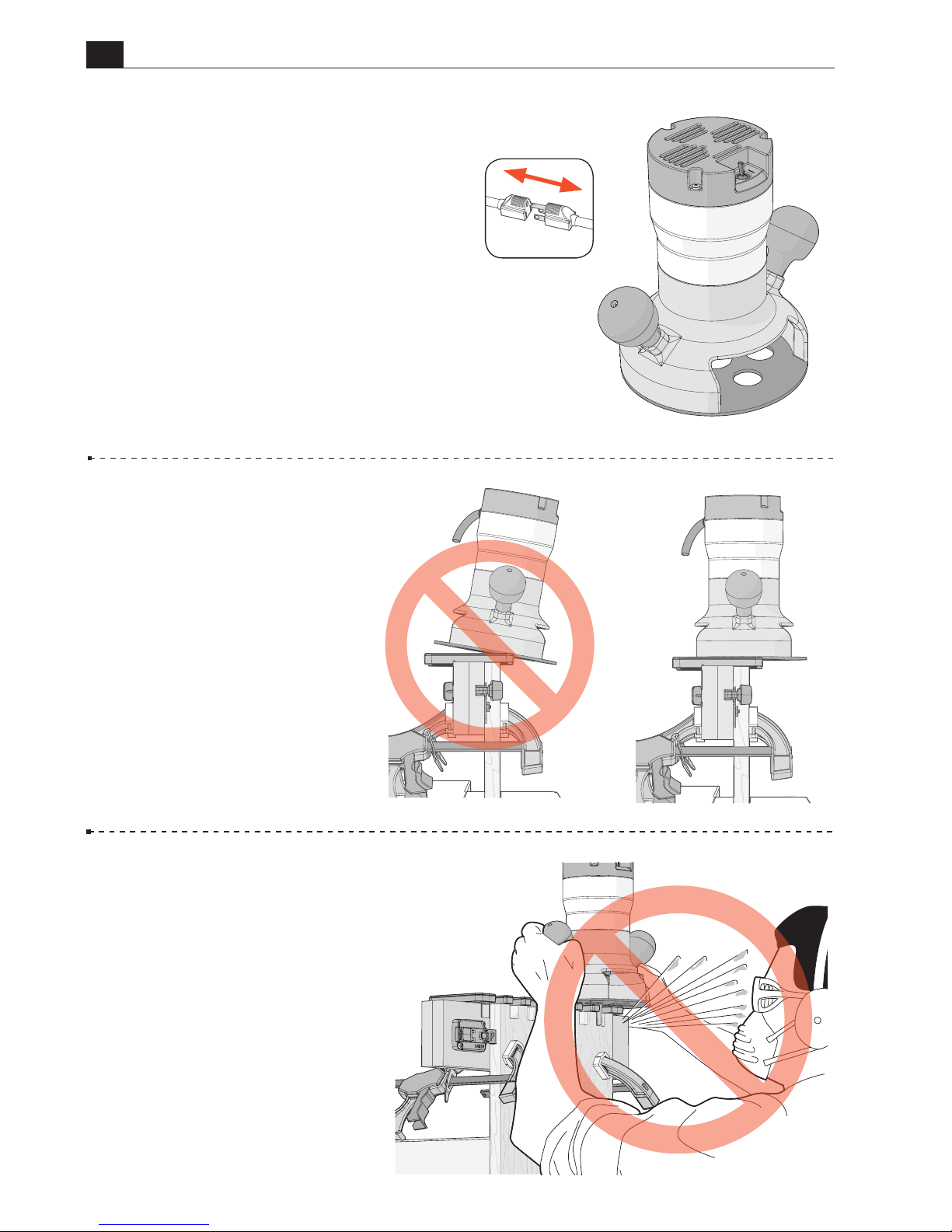
Always disconnect the power
source before installing bits, guide
bushings or making adjustments. Before
reconnecting the router to the power
source, make sure the bit and collet
revolve freely with and without the
guide bushing in place.
After routing, wait for the bit to come
to a complete stop before removing the
router from the jig.
Never rout at face level.
Chips and sawdust are thrown out at
high speed. ■
Do not tilt the router.
Keep
the router flat on the jig during all
routing.
Page 11
11
B975 User Guide
CHAPTER 3
The Leigh e10 eBush
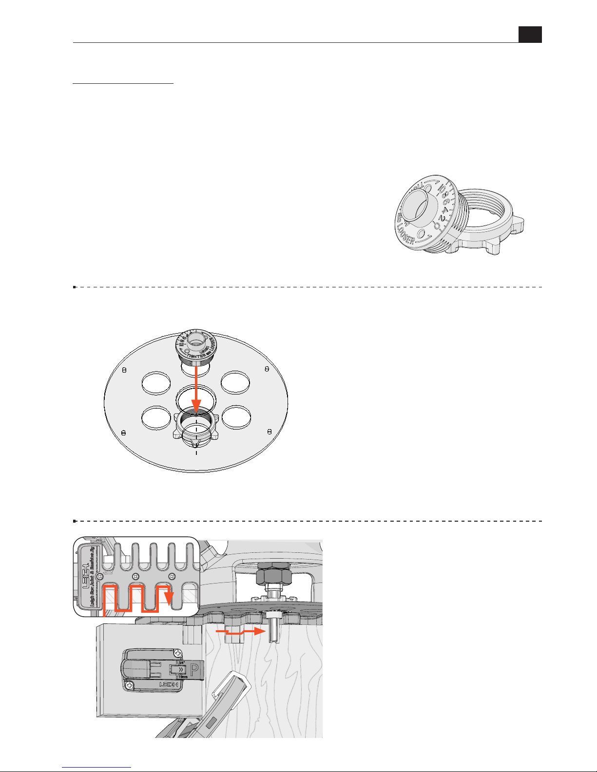
3-2 The barrel of the e10 steers
the router and the bit in and around
the openings of the template.
3-1 How the e10 Works
Routing on the B975 requires a
router fitted with the included e10
eBush (guide bushing).
The e10 is installed in the base of
the router and the guide bushing
retaining nut is screwed on, under
the router base.
Patents for Leigh elliptical guide bushings: U.S. 9,375,860 UK GB2443974
Note: Normal tolerances with bits, guide bushings
and router runout will generally produce poor fitting
joints. The included Leigh e10 elliptical guide bushing
(eBush) solves this problem.
Page 12
12
B975 User Guide
12
Chapter 3 The Leigh eBush
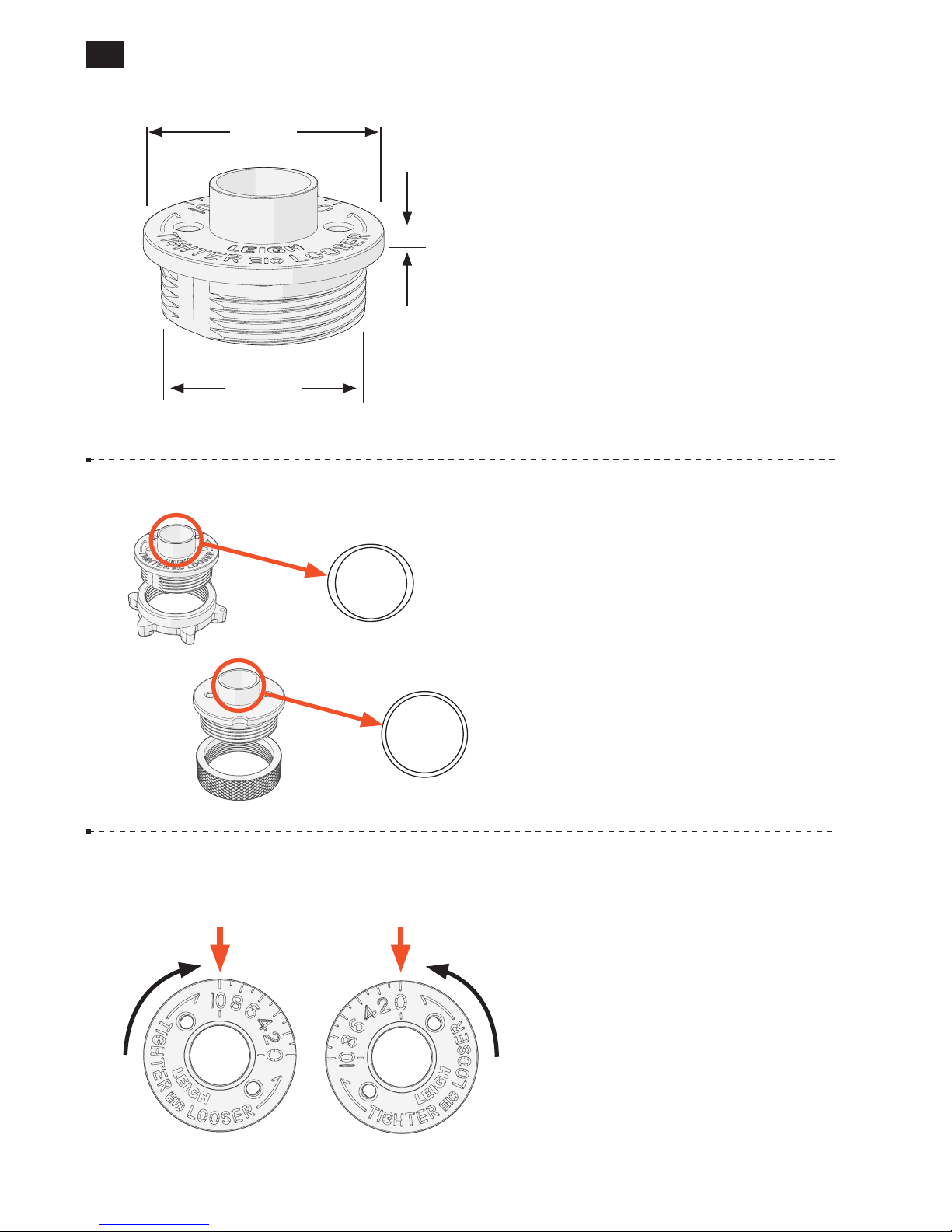
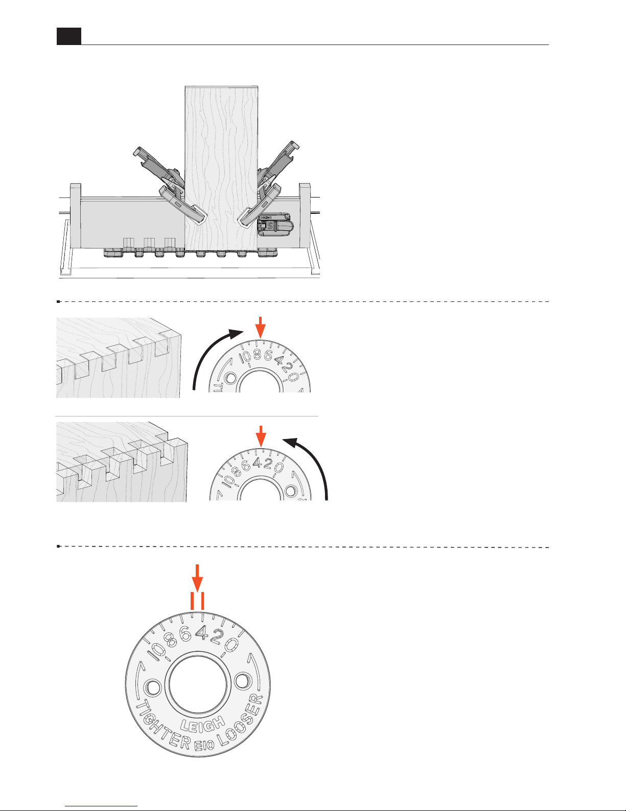
3-5 All routing starts with
the eBush in the No.5 position.
This allows adjustment for a tighter
or looser fit. Turning the eBush
toward the 10 position A results in a
tighter fit. Turning the eBush toward
the 0 position B results in a looser fit.
Be sure to retighten the e-Bush
nut after each adjustment.
A
B
3-4 The Leigh eBush barrel
A
is elliptical , unlike plain circular
template guide bushings B. When
the e10 is rotated, the effective
diameter of the barrel changes,
allowing fit adjustments as small as
0.001"[0.025mm]. The e10 eBush
is included with the jig.
B
A
3-3 The Leigh eBush System is
designed around the 1-3/8" industry
standard. Some routers accept the
Leigh eBush directly. Many routers
require the use of a guide bushing
adapter. If your router requires an
adapter, please see the Guide Bushing
Adapter chart and Leigh guide
bushing adapters in Chapter 8.
1
3
/16"
0.100"
1
3
/8"
Page 13
13
B975 User Guide
Chapter 3 The Leigh eBush
3-6
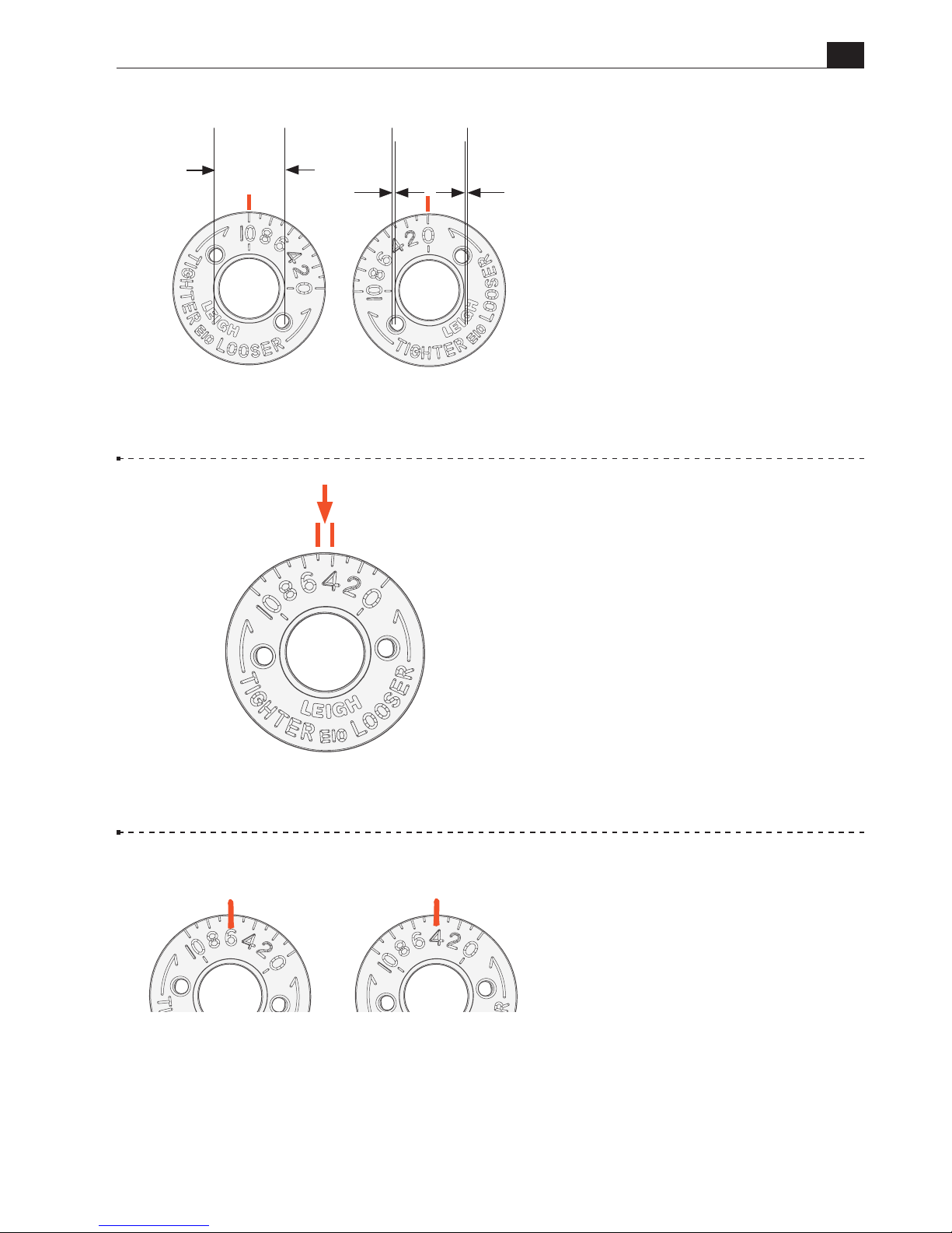
Joint Fit Adjustment The
effective diameter of the e10 is 5/8" at
the 10 position. Rotating the eBush
to the 0 position reduces the effective
diameter by 0.020"[0.5mm].
5/8"
0.010"
0.010"
3-7 One increment of the eBush
changes the joint glue line by
0.002"[0.05mm]. Half an increment
changes the fit by an incredible
0.001"[0.025mm]. A perfect fit will
be established with one or two test
cuts.
3-8 Each chapter provides a place
to mark your perfect eBush setting,
for easy repeatability the next time.
May 5, 3/4" joint
Walnut, 160 bit
Feb.28, 1/2" joint
Maple, 160 bit
EXAMPLE ONLY
Page 14
14
B975 User Guide
14
Chapter 3 The Leigh eBush
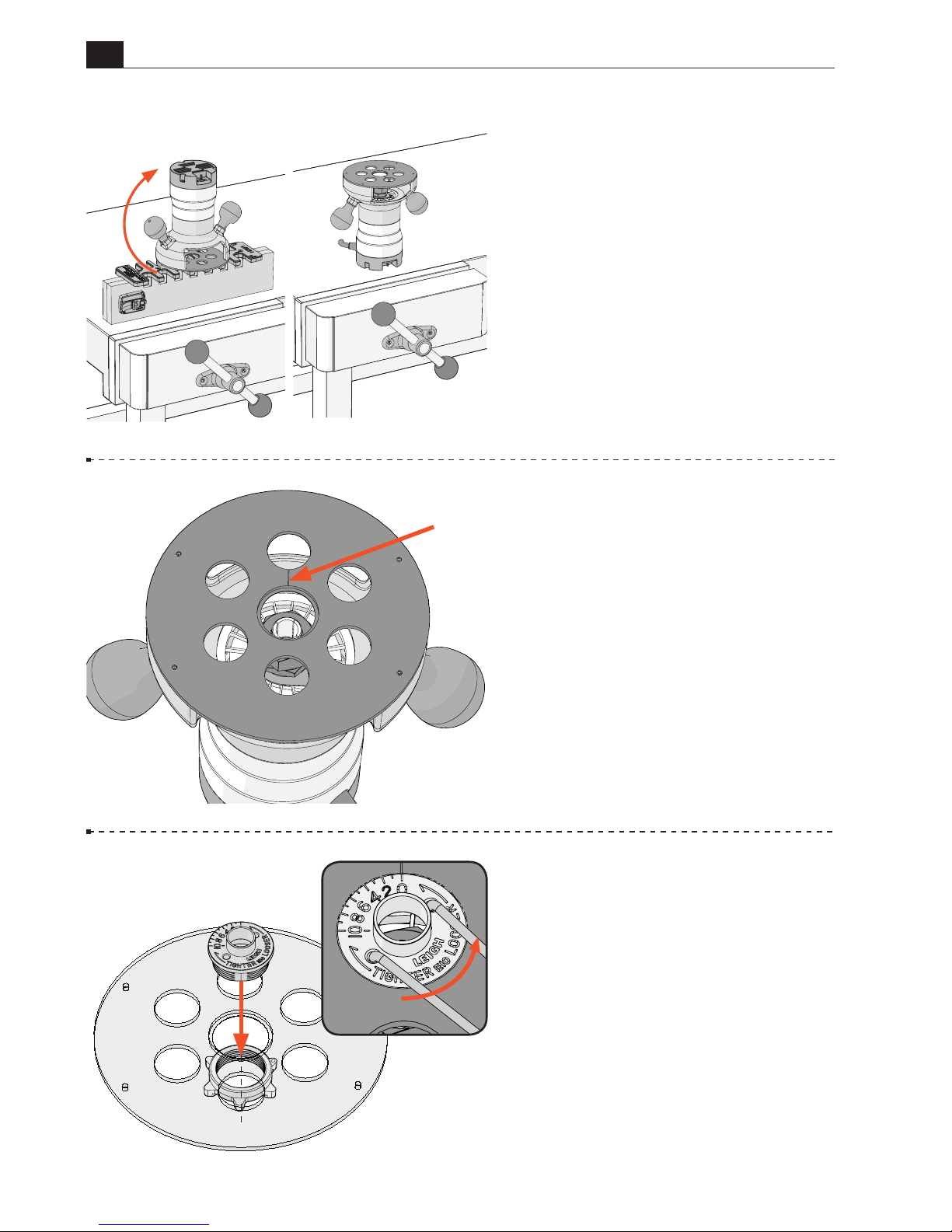
3-11 Install the e10-Bush in the
router base and use the pin wrench
to align the 0 to the reference line.
The 0 setting is only used for beam
preparation. All other routing begins
with the eBush set to 5.
Be sure to retighten the eBush
nut after each adjustment.
■
3-10 Make a small scratch line on
the router base or eBush adapter,
at the 12 o’clock position. This will
be a reference line for all eBush
settings A.
3-9
Fitting the eBush to the
Router. Place the router on the jig
with handles positioned the way you
would normally hold the router A.
Then turn the router upside down
and place it on the workbench B,
keeping the same face of the router
toward you.
A
A
B
A
Page 15
15
B975 User Guide
CHAPTER 4
Mounting
& Assembly
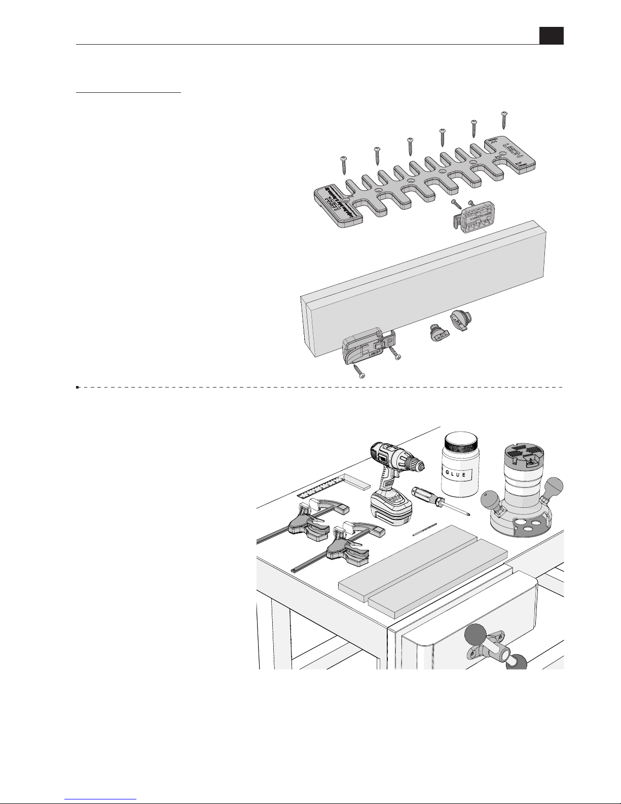
The instructions on the
following pages will guide
you through the assembly
process for the Leigh B975.
You will need:
• A workbench with vice or a
portable workbench
• 2 pieces of 3/4" MDF to make
a beam 1-1/2"x 3-1/2" x 16"
[38mm x 90mm x 406mm]
• Router with 1/2" collet
• Electric drill, preferably bench
or pedestal, but handheld will
work
• 1/8" drill bit
• Two Quick-Grip clamps
• Square, ruler or tape measure
• No.2 Phillips screwdriver
• Wood Glue
Page 16
16
B975 User Guide
Chapter 4 Mounting & Assembly
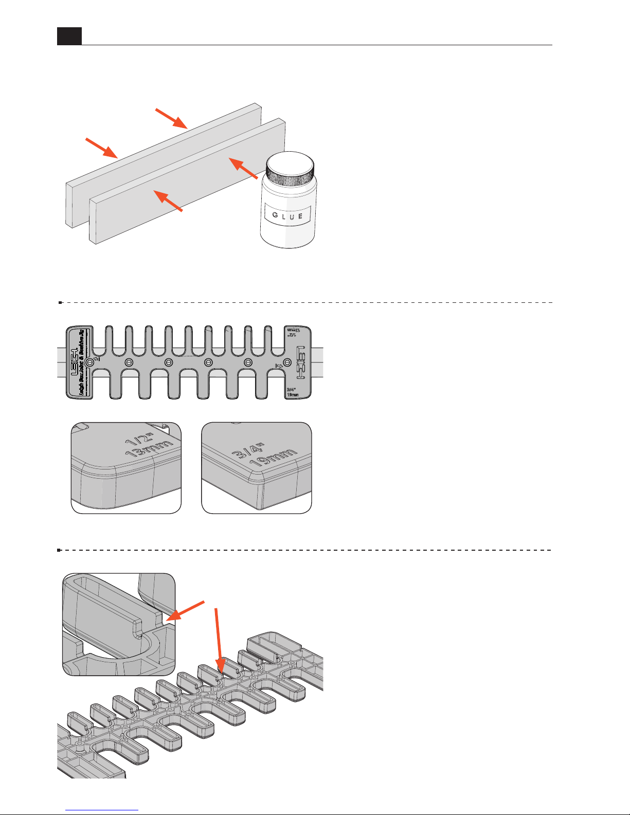
4-1 Making the Beam We
recommend laminating the two
pieces of 3/4" MDF. Place the glued
pieces in a vice or use clamps to hold
them together. The template will be
attached to the top of the beam, so
be sure the top edges are flush and
free of glue residue. Set aside to dry
completely. Alternatively, a common
2x4 may be used. See step 4-15 for
special instructions.
4-3 The 1/2" comb has position-
ing ridges A molded into the
bottom side of the template.
A
4-2 One side of the template is
used for 3/4" box joints and the
other side is used for 1/2" joints.
Page 17
B975 User Guide
Chapter 4 Mounting & Assembly
17
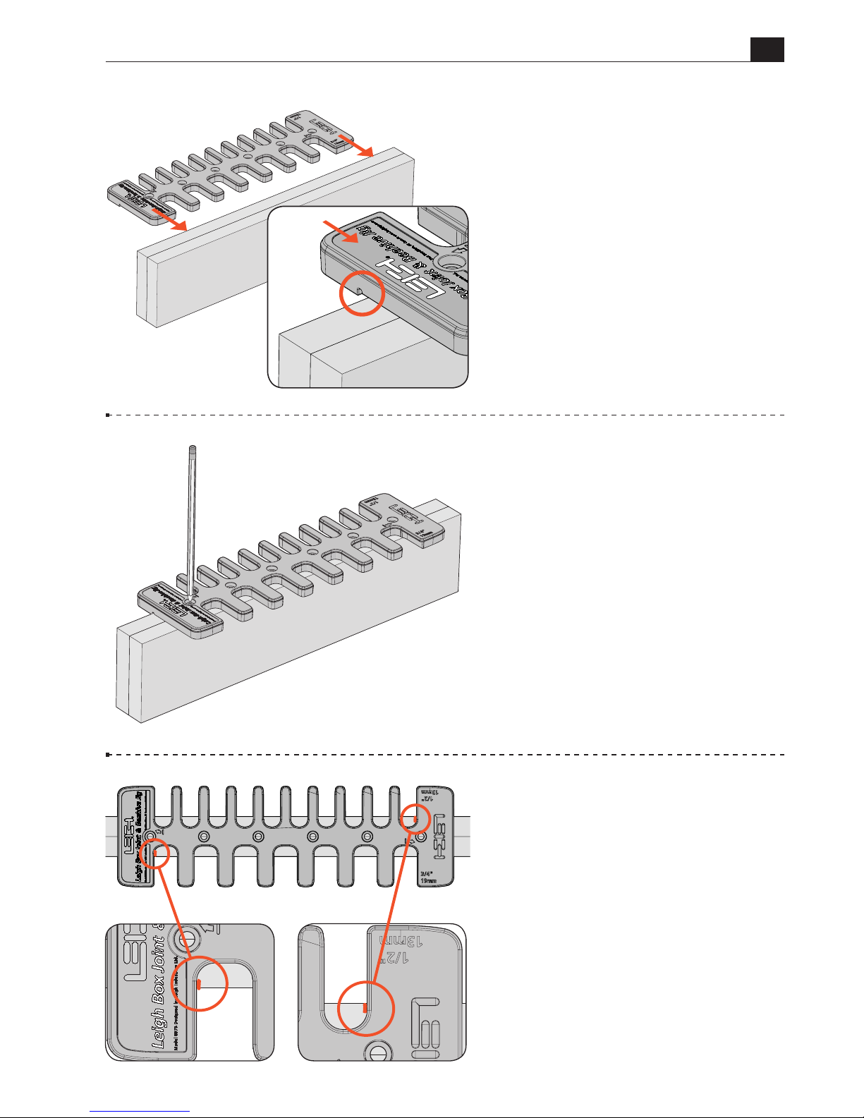
4-4 With the 3/4" comb facing
you, lay the template flat on the
beam and center it left to right. Slide
the template forward until the ridges
on the underside of the 1/2" comb
contact the back of the beam. The
template is now positioned correctly.
4-5 Use a pencil and mark the
location of all screw holes on the top
of the template. Hold the template in
place and proceed to the next step.
4-6 Make a pencil line on the top
of the beam at each end of the jig on
the 3/4" and 1/2" sides.
Page 18
18
B975 User Guide
Chapter 4 Mounting & Assembly
4-8 Mark layout lines for the side
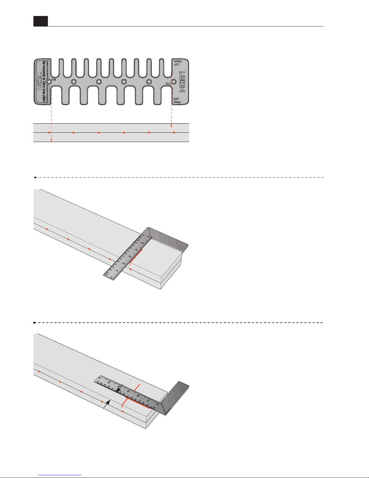
stops. First, place the beam flat on
the workbench with the 1/2" side
of the beam facing up. Use a square
and draw a vertical line down from
the positioning mark on the top of
the beam.
4-9 Next, draw a horizontal line,
1" down from the top of the beam.
Rotate the beam and repeat for the
3/4" side.
4-7 Remove the template and
mark 3/4" and 1/2" beside the lines,
to indicate which is the 3/4" and
which is the 1/2" side of the beam.
1"
3/4 "
1/2 "
1/2 "
1/2 "
Page 19
B975 User Guide
Chapter 4 Mounting & Assembly
19
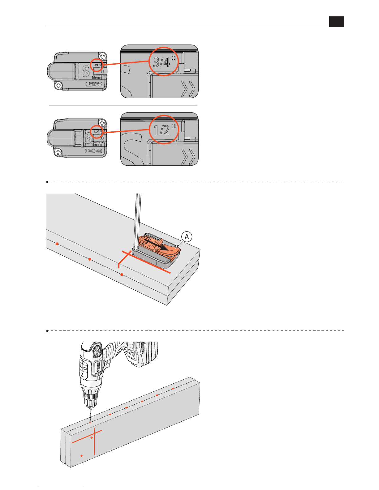
4-11 Install the 3/4" side stop. Lift
the thumb lock A, retract the center
portion of the 3/4" side stop fully
and press the thumb lock down to
lock it in place. Position it against
the layout lines as shown.
Use a pencil to mark the screw hole
locations.
Rotate the beam and repeat the
process for the 1/2" side.
4-12 Use a drill press or hand drill
with a 1/8" bit to drill pilot holes at
all screw hole locations.
4-10
The 3/4" and 1/2" side stops
will be attached in the following
steps.
3/4" Side Stop
1/2" Side Stop
3/4"
Page 20
20
B975 User Guide
Chapter 4 Mounting & Assembly
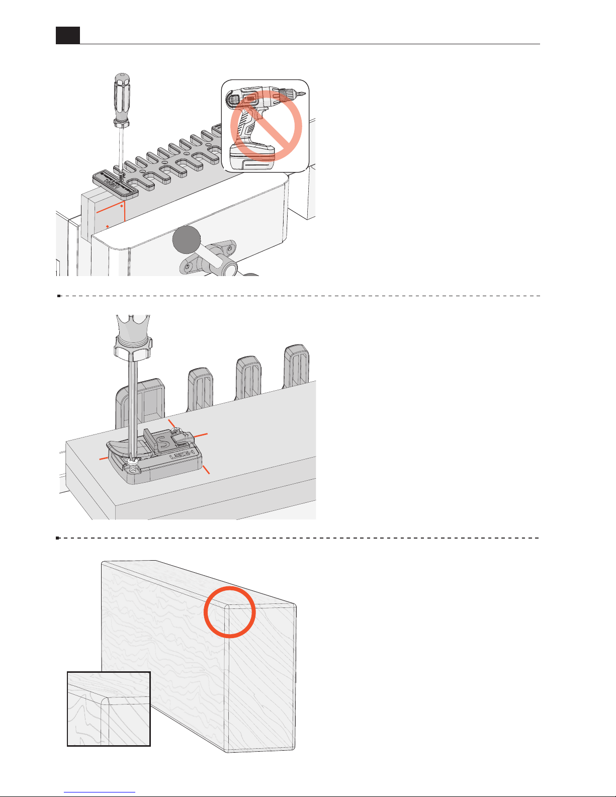
4-15 Alternatively, you can use
a straight, flat 16"[406mm] piece
of common 2x4. Since a 2x4 has
slightly rounded corners, the top
edge should be squared off.
4-14 Place the beam on the
workbench with the 3/4" side of the
beam facing up. Position the 3/4"
side stop against the horizontal and
vertical lines, with the thumb lock
facing the left end of the beam, and
attach it using the included screws.
Again, use a screwdriver, not a power
drill, to attach the side stop.
Repeat the process with the 1/2" side
stop on the 1/2" side of the beam.
4-13 Clamp the beam in the vice
with its 3/4" side facing you. Position
the template on the beam with the
3/4" side of the template facing you.
Align it with the pre-drilled holes.
Use a screwdriver to attach the
template with six of the included
screws.
Do not use a power
drill, as this may overstress the
template.
Page 21
B975 User Guide
Chapter 4 Mounting & Assembly
21
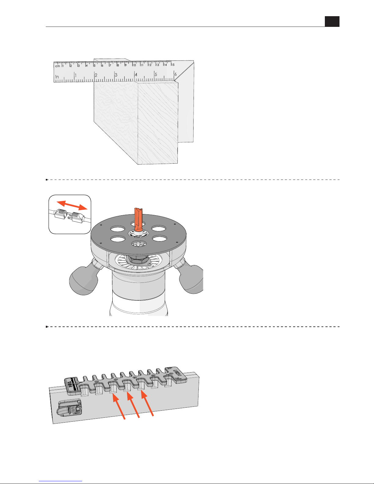
4-16
Use a table saw, router table or
jointer to skim off the top surface of
the 2x4. Now go back to step 4-7 for
the rest of the beam preparation.
4-18 Prepare the Beam
To prevent tearout of the beam,
grooves must be routed in all
template openings, on both sides of
the beam, as shown in the following
steps.
Preparing the beam is particularly
important when using a common
2x4 because its side grain will tear
out badly.
4-17
Install the Bit
Install the No.160 1/2" straight bit
(or equivalent) in the router. The bit
goes through the guide bushing and
fits in the router collet.
Tighten the collet and rotate the bit
and collet to ensure it spins freely
and does not contact the eBush or
eBush nut.
Page 22
22
B975 User Guide
Chapter 4 Mounting & Assembly
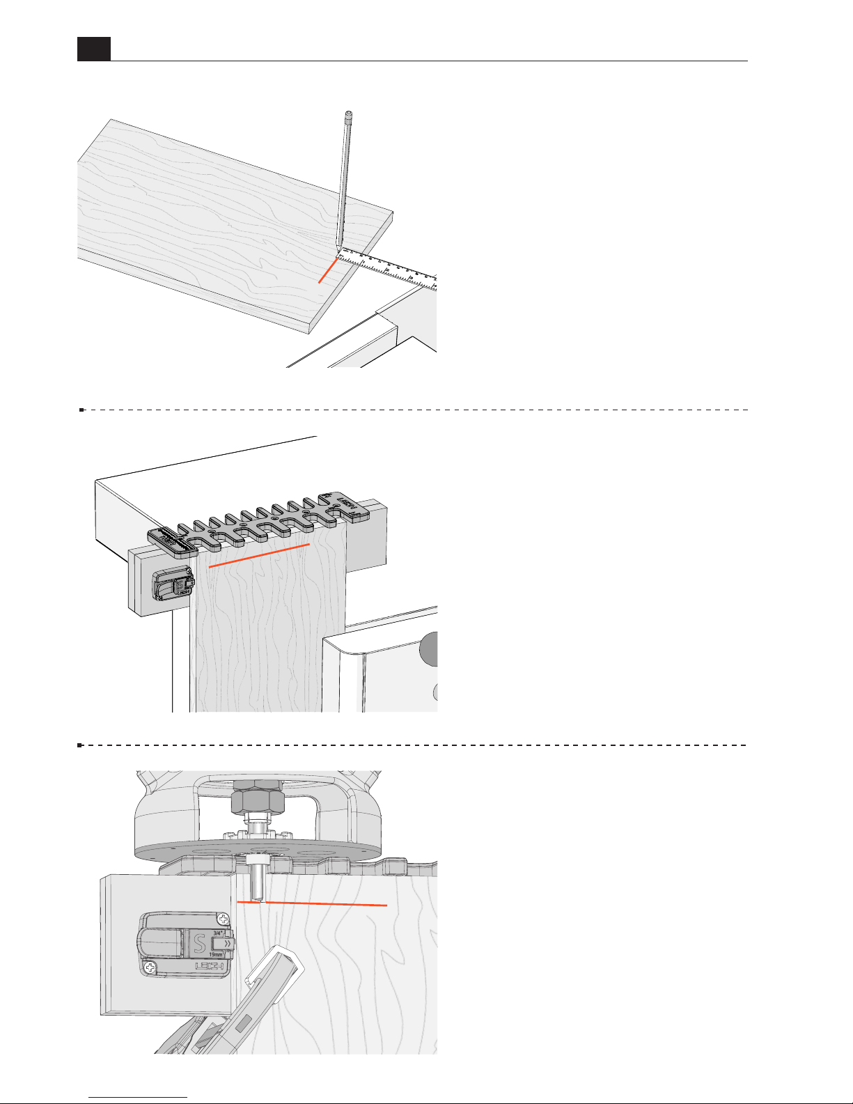
4-20 With the socket board stop
fully retracted, and the 3/4" side of
the jig facing you, lower the jig onto
the board. Slide the jig over until the
left edge of the board touches the
socket board stop as shown.
Clamp the jig in place.
4-21 Place the router on the jig and
adjust the tip of the bit up or down
until it’s at the center of the line.
Rotate the bit and collet to ensure
it spins freely and does not contact
the eBush.
4-19 Depth of Cut
Select a board at least 9-3/4"
[248mm] wide and 1/2" to 3/4"
thick. Length is not important as
long as it can be clamped safely in
the vice.
Set the depth of cut by marking a line
3/4" from the top end of the board.
Clamp the board in the vice with the
depth of cut line facing you.
Page 23
B975 User Guide
Chapter 4 Mounting & Assembly
23
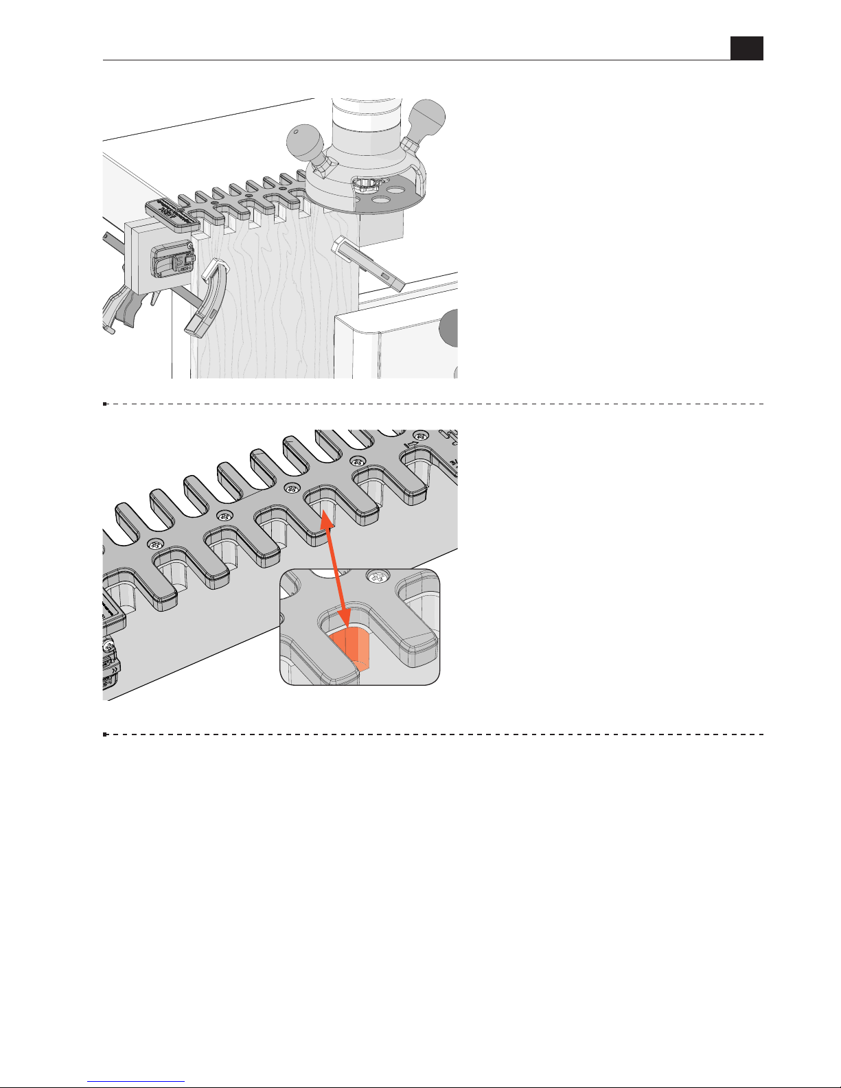
4-22 Hold the router firmly and
rout through the board and into the
beam, in each template opening.
Be sure the guide bushing touches
the left side of each template opening
on the way in and the right side on
the way out.
Use the other end of the board and
repeat for the 1/2" side of the jig.
4-23 There will now be a clean
groove in each template opening on
both sides of the beam.
The beam and jig are now ready to
use.
■
Page 24

24
B975 User Guide
Chapter 4 Mounting & Assembly
This page is left blank intentionally.
Page 25
25
B975 User Guide
CHAPTER 5
Routing Box Joints
Note: Routing Procedures for 3/4" and 1/2"
joints are identical. This chapter shows
steps for 3/4" joints.
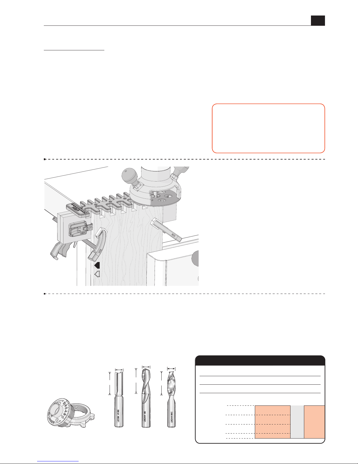
5-1 Getting Started The steps
in this chapter show the jig used
on a workbench. For router table
operation, see Chapter 7.
5-2
Parts Required 3/4" and 1/2" box joints are routed with the included Leigh
No.160 1/2" straight bit and the Leigh e10 guide bushing (eBush).
No other bit diameter
and guide bushing combination may be used.
Maximum board thickness for both
joint sizes is 13/16"[20.6mm]. Depth of cut can be increased beyond the board thickness
for raised joints. Note: Optional 1/2" diameter spiral upcut bits may also be used.
1/2"
1/2"
1/4"
3/4"
0"
13/16"
160
180
Depth of Cut
Item No. Carbide Tipped
Bit Diameter
Item No.
Spiral HSS (Optional)
Item No. Spiral Solid Carbide (Optional)
180C
Bit Cutting Depth
160
(included)
e10
Guide Bushing
180 180C
(Optional Bits)
1-1/4"
1/2"
1/2"
1-3/4"
1/2"
1-5/8"
P
IMPORTANT SAFETY NOTE
Before using your Leigh B975, you must
have completed the preparatory steps
listed in the previous pages, including
reading the jig safety recommendations
in Chapter 2.
Page 26
26
B975 User Guide
Chapter 5 Routing Box Joints
5-3
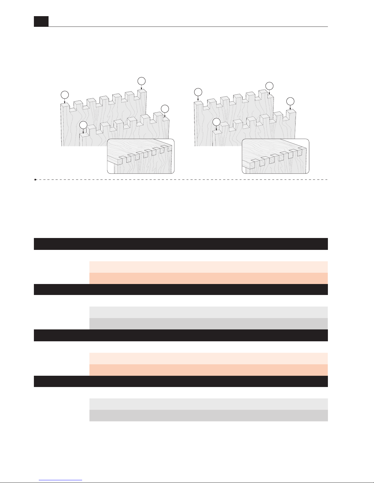
Joint layout
Review the drawings below.
Symmetrical
joints have pins Aon both
edges of the pin board, and sockets
B
on both edges of the socket board.
Asymmetrical
joints have a pinCon one edge and a socketDon the other edge of each board.
5-4
Board Width Selection
Board widths are determined by the total number of pins
and sockets in the joint design and whether the joint is symmetrical or asymmetrical. Use
this chart to determine board widths up to the full width of the jig: 9-11/16"[246 mm].
Routing box joints on wider boards will be covered in Chapter 6.
Symmetrical Board Widths for
¾
"
Box Joints
Total Pins & Sockets
3 5 7 9 11 13
Inches 2 /" 3 /" 5 /" 6 /" 8 /" 9 /"
Millimeters 56 94 132 170 208 246
Asymmetrical Board Widths for
½
"
Box Joints
Total Pins & Sockets
4 6 8 10 12 14 16 18
Inches 1 /" 3" 4" 5 /" 6 /" 7 /" 8 /" 9 /"
Millimeters 50 76 102 128 154 180 206 232
Asymmetrical Board Widths for
¾
"
Box Joints
Total Pins & Sockets
4 6 8 10 12
Inches 2 /" 4 /" 5 / " 7 /" 8 /"
Millimeters 75 113 151 189 227
Symmetrical Board Widths for
½
"
Box Joints
Total Pins & Sockets
3 5 7 9 11 13 15 17 19
Inches 1 /" 2 /" 3 /" 4 /" 5 /" 6 /" 7 /" 8 /" 9 / "
Millimeters 37 63 89 115 141 167 195 219 245
B
B
D
D
C
C
A
A
Asymmetrical
Symmetrical
Socket Board
Pin Board
Socket Board
Pin Board
Page 27
B975 User Guide
Chapter 5 Routing Box Joints
27
5-5
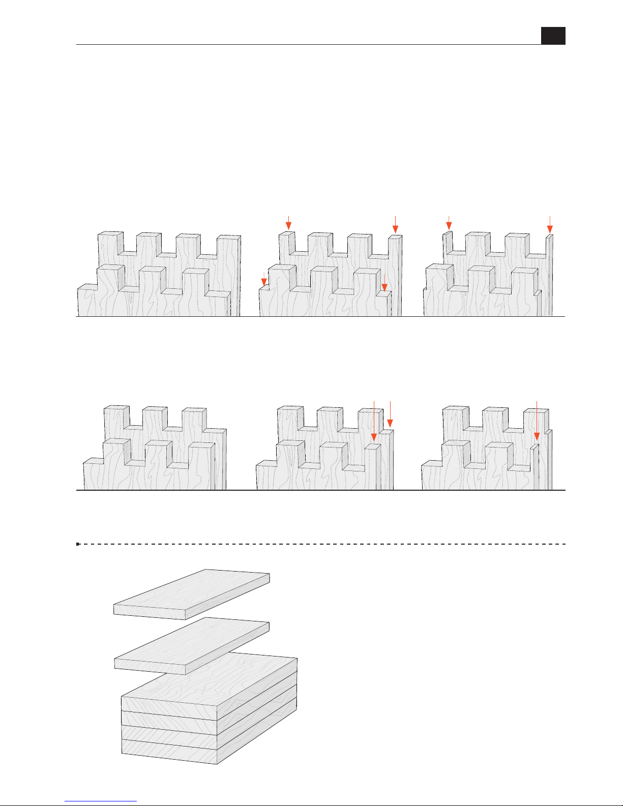
Board Width Selection Board widths indicated in the chart will produce full size
pins and sockets at each board edge, for symmetrical or asymmetrical joints. Symmetrical
joint board widths may be reduced as required, resulting in smaller but equally sized pins
and sockets at each board edge. If board widths are reduced for asymmetrical joints, one
edge of the board will have a full size pin and socket while the other board edge will have
a smaller pin and socket. This may result in an unattractive joint.
IMPORTANT:
Read this chapter
before routing any boards.
5-6 Making a Box Prepare
four similar boards 3/4" thick ×
5-3/16" wide by about 12" long
[19mm×133mm×305mm], and two
test boards, about 4"[100mm] wide
and the same thickness.
Note: Boards of different thicknesses
may also be joined.
Symmetrical
Asymmetrical
Full size
pins and sockets
Full size
pins and sockets
When a symmetrical board width is reduced,
the joint will have smaller, but equal sized
pins and sockets at each edge of the board.
Width specified in the board width chart
results in full size pins and sockets at each
edge of the board.
Width specified in the board width chart
results in a full size pin at one edge of the
board, and a full size socket at the other edge
of the board.
When an asymmetric board width is reduced,
the joint will have a full size pin and socket at
one edge of the board, and a reduced size pin
and socket at the other edge of the board.
When the board width is reduced further,
the result is very narrow and fragile pins at
each edge of the board.
When the board width is reduced further,
the result is a very narrow and fragile pin at
one edge of the board.
Small pins can break easily
Small pin
can break easily
Reduced size pins and sockets
Reduced size
pin and socket
Page 28
28
B975 User Guide
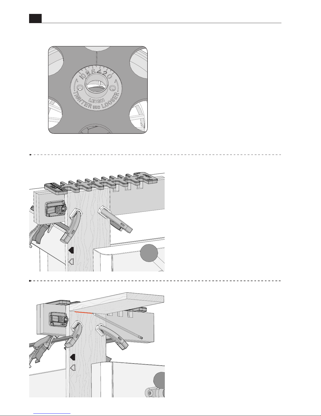
Chapter 5 Routing Box Joints
5-9 Socket and pin boards may
differ in thickness. Always use
the mating pin or socket board to
determine depth of cut. Hold it flush
under the template and mark a line
on the board, indicating depth of
cut.
5-7 Routing a Test Fit Joint
Test joints are always routed with the
eBush set at the 5 position.
Retighten the eBush nut after each
guide bushing adjustment.
5-8 Clamp one of the test boards
in the vice. Using the 3/4" side of
the jig, position the left end of the
jig over the test board and clamp in
place.
Board alignment is not important
when routing a test fit.
Page 29
B975 User Guide
Chapter 5 Routing Box Joints
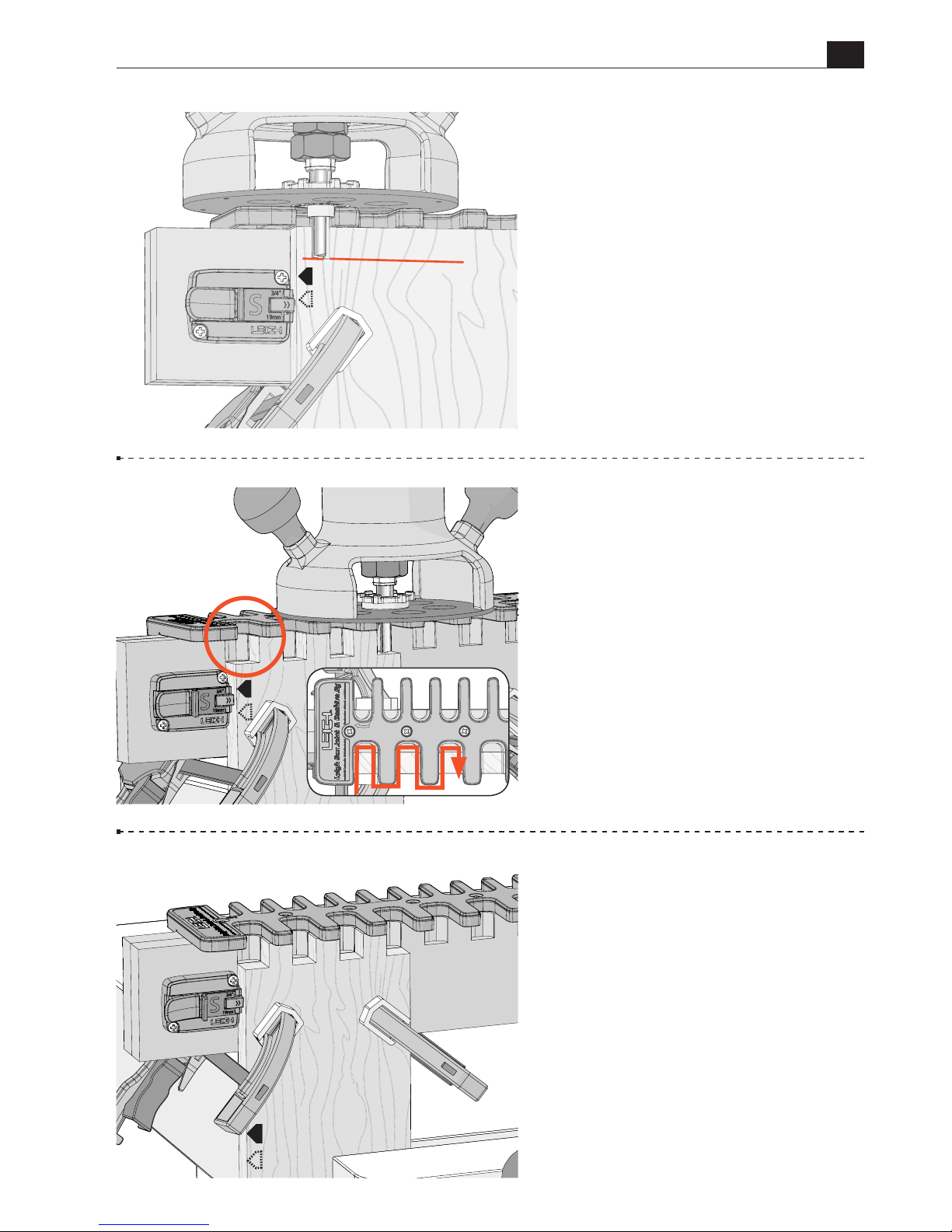
29
5-11
Rout the first test board.
Hold the router firmly as you rout
straight in and out of each template
opening. Be sure the e10 guide
bushing touches the left side of the
template opening on the way in, and
the right side on the way out.
Do not
rotate the router.
5-12 Remove the jig from the first
test board and repeat the process for
the second test board.
5-10 Place the router on the jig and
adjust the tip of the bit up or down
until it’s at the center of the line.
Rotate the bit and collet to ensure
it spins freely and does not contact
the eBush.
Page 30
30
B975 User Guide
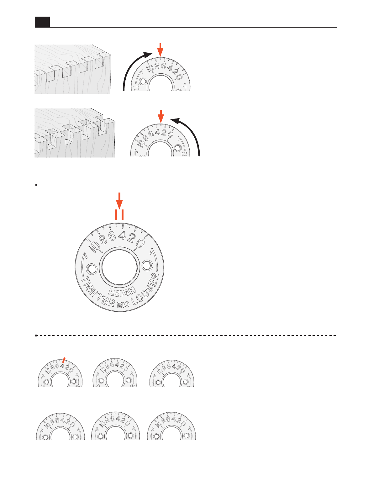
Chapter 5 Routing Box Joints
5-14
Each increment on the
eBush changes the joint glue line
fit by 0.002"[0.05mm]. Half an
increment, a mere 0.001"!
Retighten the eBush nut after
each guide bushing adjustment.
5-13 Joint Fit Adjustment
Assemble the test boards. If the joint
is too loose, use the pin wrench and
turn the eBush to a higher number
and rout two fresh board ends.
If the joint is too tight, turn the
eBush to a lower number and rout
two fresh board ends.
One or two test cuts should produce
a perfect fit.
5-15 Use these eBush diagrams
to record the settings you used to
achieve perfect joint fit. The first
eBush is simply an example of how
to record your setting.
35
TOO LOOSE
TIGHTEN
TOO TIGHT
LOOSEN
SAMPLE
June7, 1/2"joint
Maple, 160 bit
Page 31
B975 User Guide
Chapter 5 Routing Box Joints
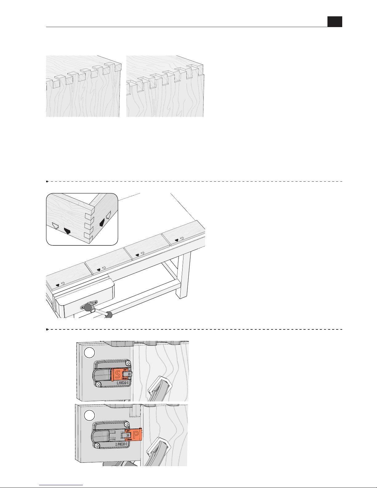
31
5-16 Joint flushness is determined
by the depth of cut.
If the joint is over flush, raise the bit
to decrease the depth of cut.
If the joint is under flush, lower the
the bit to make a deeper cut.
OVER FLUSH UNDER FLUSH
5-17
Lay out the four boards for the
box. Mark an S (socket board) on two
of the boards and a P (pin board) on
two boards.
Also mark the common board edges
that will go against the side stop.
These edges will align at the top
or bottom edge of the box when
assembled.
A
B
5-18
Side Stop Positions
The
side stop is used to position the pin
and socket boards. Put the socket
board stop in the S position Afor
all socket boards. The pin board stop
is put in the P position B for all pin
boards.
P
P
S
S
P
S
S
P
Page 32
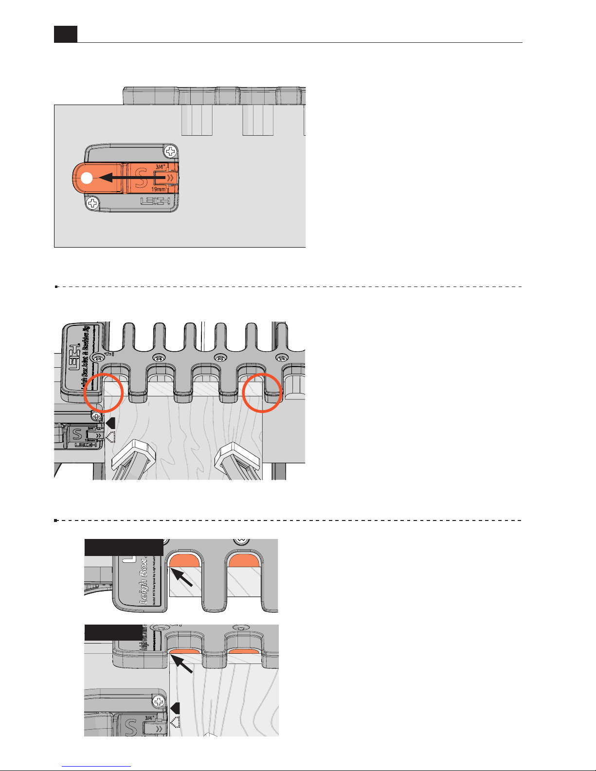
32
B975 User Guide
Chapter 5 Routing Box Joints
5-19
Routing the Socket Board
With the 3/4" side of the template
facing you, lift the thumb lock A
and move the socket board stop fully
to the left. Lock it in position.
5-20 Symmetrical Joints
Clamp the first socket board in the
vice. With the left edge of the board
in the first template opening, position
the jig over the socket board, leaving
equal amounts of the board showing
at each edge. Clamp the jig in place.
5-21 Asymmetrical Joints
Clamp the first socket board in the
vice. With the left edge of the board
in the first template opening, position
the jig over the socket board.
Note:
Asymmetrical boards cannot
be centered under the template.
With the side stop fully retracted,
align the left edge of the board with
the left edge of the groove in the
beam.
S
A
S
Overhead View
Front View
Page 33
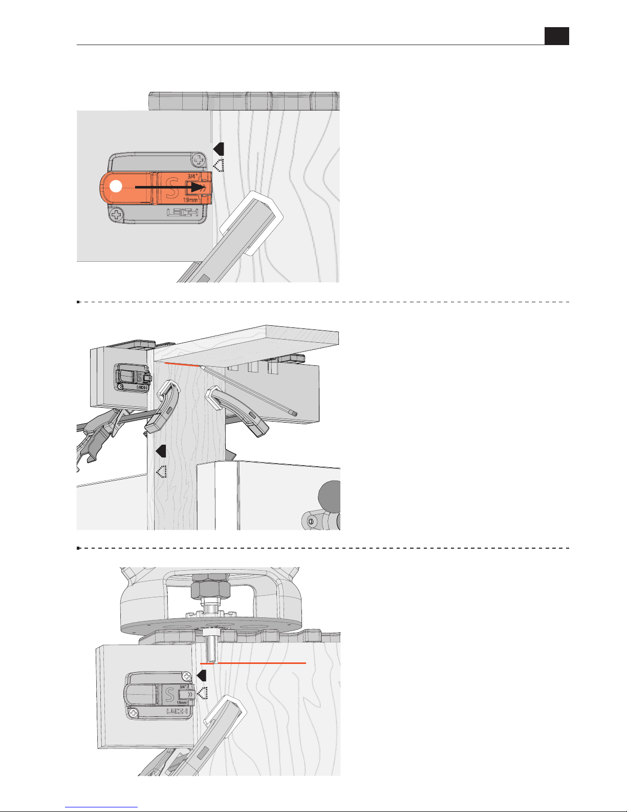
B975 User Guide
Chapter 5 Routing Box Joints
33
5-22 For both joint types, lift
the thumb lock A, and move the
socket board stop to the right until
it touches the board. Press the thumb
lock to lock it in place.
The side stop remains locked in place
for all socket and pin board routing.
5-23 Socket and pin boards can
be different thicknesses. Always use
the mating pin or socket board to
determine depth of cut.
In this case, hold the pin board flush
under the template and draw a line
on the socket board, indicating
depth of cut.
5-24
Place the router on the jig and
adjust the tip of the bit up or down
until it’s at the center of the line.
Rotate the bit and collet to ensure
it spins freely and does not contact
the eBush.
A
S
S
S
Page 34
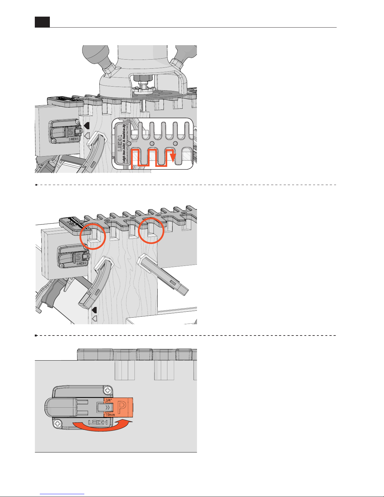
34
B975 User Guide
Chapter 5 Routing Box Joints
5-25 Hold the router firmly, as
you rout straight in and out of each
template opening.
Be sure the e10 guide bushing
touches the left side of the template
opening on the way in, and the
right side on the way out. Do not
rotate the router. Keep the router
handles parallel to the jig while
routing.
5-26
There will now be a full socket
at each edge of the socket board.
Turn the socket board end for end,
keeping the same board edge against
the side stop.
Rout the other end of the board.
Repeat for the second socket board
and remove the jig from the socket
board.
S
5-27 Routing the Pin Board
The pin board must be offset relative
to the socket board. Do not release
the thumb lock. Simply flip the pin
board stop to the P position.
Page 35
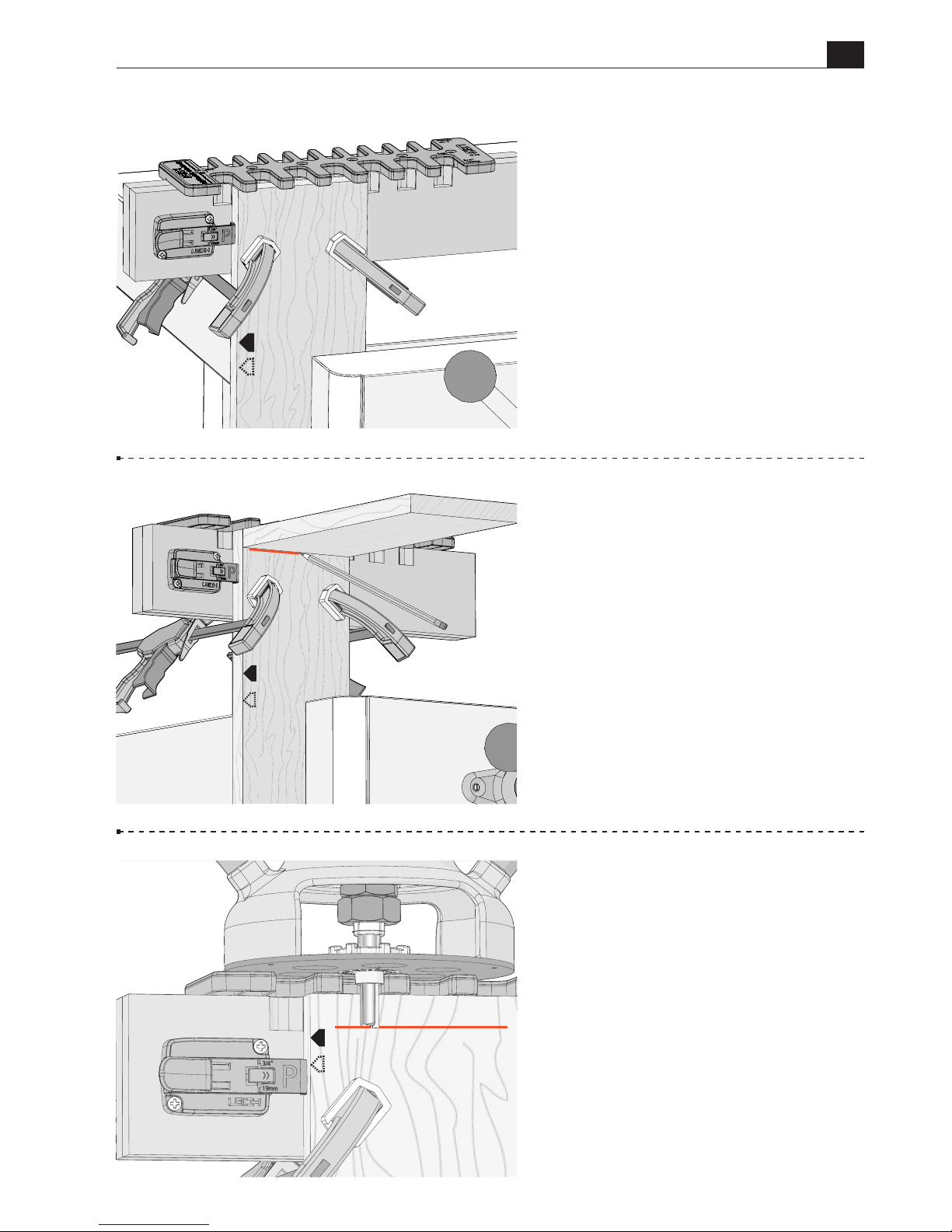
B975 User Guide
Chapter 5 Routing Box Joints
35
5-29 Use the socket board to mark
the depth of cut. If all your boards
are the same thickness, the depth is
already set.
5-30
Place the router on the jig and
adjust the tip of the bit up or down
until it’s at the center of the line.
P
P
5-28 With the side stop set,
position the jig over the pin board,
and slide it over until the side stop
touches the board edge. Clamp in
place.
P
Page 36
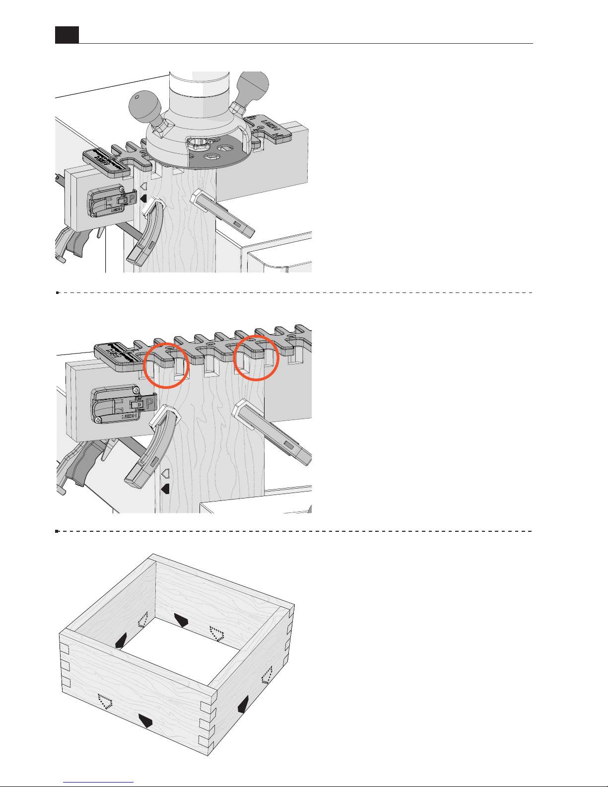
36
B975 User Guide
Chapter 5 Routing Box Joints
5-32
There will now be a full pin
at each edge of the board.
Turn the pin board end for end,
keeping the same board edge against
the side stop, and rout the other end
of the board. Repeat for the second
pin board.
5-33 Assemble the box, keeping the
marked board edges aligned.
■
P
P
P
S
S
5-31 Hold the router firmly as
you rout straight in and out of each
template opening. Be sure the e10
guide bushing touches the left side
of the template opening on the way
in, and the right side on the way out.
Do not rotate the router.
P
Page 37
37
B975 User Guide
CHAPTER 6
Routing Wider Boards
This chapter assumes you are familiar with all
procedures in this user guide and you have
established good joint fit and flushness using
test boards before routing wide boards.
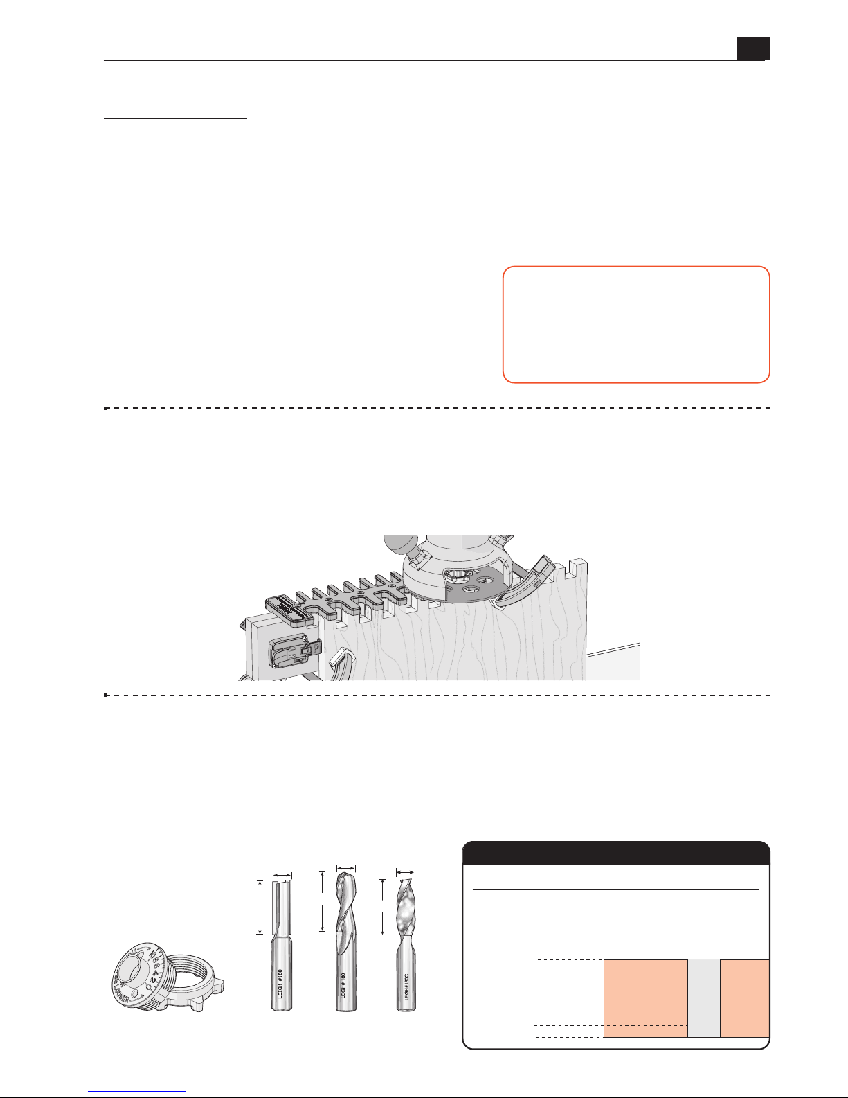
6-1 Getting Started The Box Joint & Beehive Jig can be used to rout box joints on
boards wider than the jig width, up to 17-13/16"[453mm]. This is accomplished easily
using a step-over cam and simple procedure. This example uses 3/4" box joints on 3/4"
thick boards. Procedures for routing 1/2" and 3/4" joints are identical.
6-2
Parts Required 3/4" and 1/2" box joints are routed with the included Leigh
No.160 1/2" straight bit and the Leigh e10 guide bushing (eBush).
No other bit diameter
and guide bushing combination may be used.
Maximum board thickness for both
joint sizes is 13/16"[20.6mm]. Depth of cut can be increased beyond the board thickness
for raised joints. Note: Optional 1/2" diameter spiral upcut bits may also be used.
P
1/2"
1/2"
1/4"
3/4"
0"
13/16"
160
180
Depth of Cut
Item No. Carbide Tipped
Bit Diameter
Item No.
Spiral HSS (Optional)
Item No. Spiral Solid Carbide (Optional)
180C
Bit Cutting Depth
IMPORTANT SAFETY NOTE
Before using your Leigh B975, you must
have completed the preparatory steps
listed in the previous pages, including
reading the jig safety recommendations
in Chapter 2.
160
(included)
e10
Guide Bushing
180 180C
(Optional Bits)
1-1/4"
1/2"
1/2"
1-3/4"
1/2"
1-5/8"
Page 38
38
B975 User Guide
Chapter 6 Routing Wider Boards
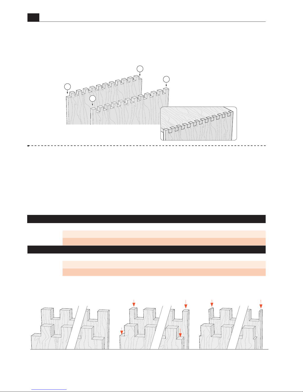
6-4
Board Width Selection Board widths are determined by the total number of
pins and sockets in the joint design. Use this chart to choose your board width.
Board widths indicated in the chart below will produce full size pins and sockets at each
board edge for symmetrical joints. Symmetrical joint board widths may be reduced as
required, resulting in smaller but equally sized pins and sockets at each board edge.
6-3
Joint layout
Review the drawing below.
Symmetrical
joints have pins
A
on
both edges of the pin board, and sockets
B
on both edges of the socket board.
Note:
Only symmetrical joints can be routed on wider boards. Asymmetrical joints are not
possible on wide boards.
A
B
B
A
Symmetrical Board Widths for
¾
"
Box Joints on Wider Boards*
Total Pins & Sockets
3 5 7 9 11 13 15 17 19 21 23
Inches 2 /" 3 /" 5 /" 6 /" 8 /" 9 /" 11 /" 12 /" 14 / " 15 /" 17 /"
Millimeters 56 94 132 170 208 246 284 322 360 398 437
Symmetrical Board Widths for
½
"
Box Joints on Wider Boards*
Total Pins & Sockets
3 5 7 9 11 13 15 17 19 21 23 25 27 29 31 33 35
Inches 1 /" 2 /" 3 /" 4 /" 5 /" 6 /" 7 /" 8 /" 9 / " 10 /" 11/" 12 /" 13 /" 14 /" 15 /" 16 /" 17 /"
Millimeters 37 63 89 115 141 167 193 219 245 271 297 323 349 375 401 427 453
*Note: Wider boards are not possible when using a router table.
Full size
pins and sockets
When a symmetrical board width is reduced,
the joint will have smaller, but equal sized
pins and sockets at each edge of the board.
Width specified in the board width chart
results in full size pins and sockets at each
edge of the board.
When the board width is reduced further,
the result is very narrow and fragile pins at
each edge of the board.
Small pins can break easily
Reduced size pins and sockets
Page 39
B975 User Guide
Chapter 6 Routing Wider Boards
39
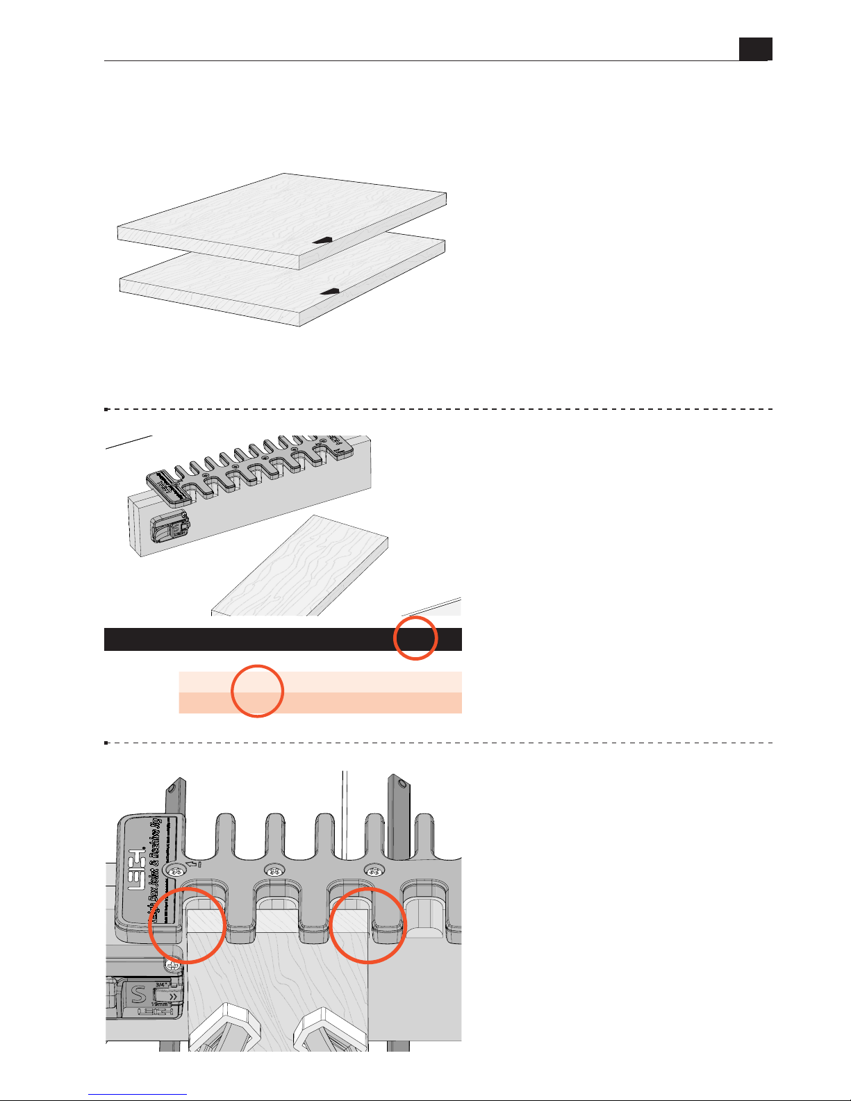
6-
5
Wood Preparation
In this
example we are using boards with
the following dimensions: 3/4" x
17-3/16" x 24" [19mm x 437mm
x 203mm].
Mark the pin and socket boards and
the board edge that goes against the
side stop.
IMPORTANT:
Read this whole
chapter before routing any
boards.
Symmetrical Board Widths for
¾
"
Box Joints on Wider Boards*
Total Pins & Sockets
3 5 7 9 11 13 15 17 19 21 23
Inches 2 /" 3 /" 5 /" 6 /" 8 /" 9 /" 11 /" 12 /" 14 / " 15 /" 17 /"
Millimeters 56 94 132 170 208 246 284 322 360 398 437
6-6 Boards wider than 9-11/16"
[246mm] cannot be centered under
the template. Therefore a narrower
board must be used to position the
side stop. Select a narrow board width
from the chart and cut a board to that
width, in this case, 3-11/16"[94mm].
S
P
6-
7
With the socket board stop fully
retracted, clamp the narrow board
in the vice and center the left end of
the template over the board, leaving
equal amounts of the board showing
at each edge. Clamp the jig in place.
Page 40
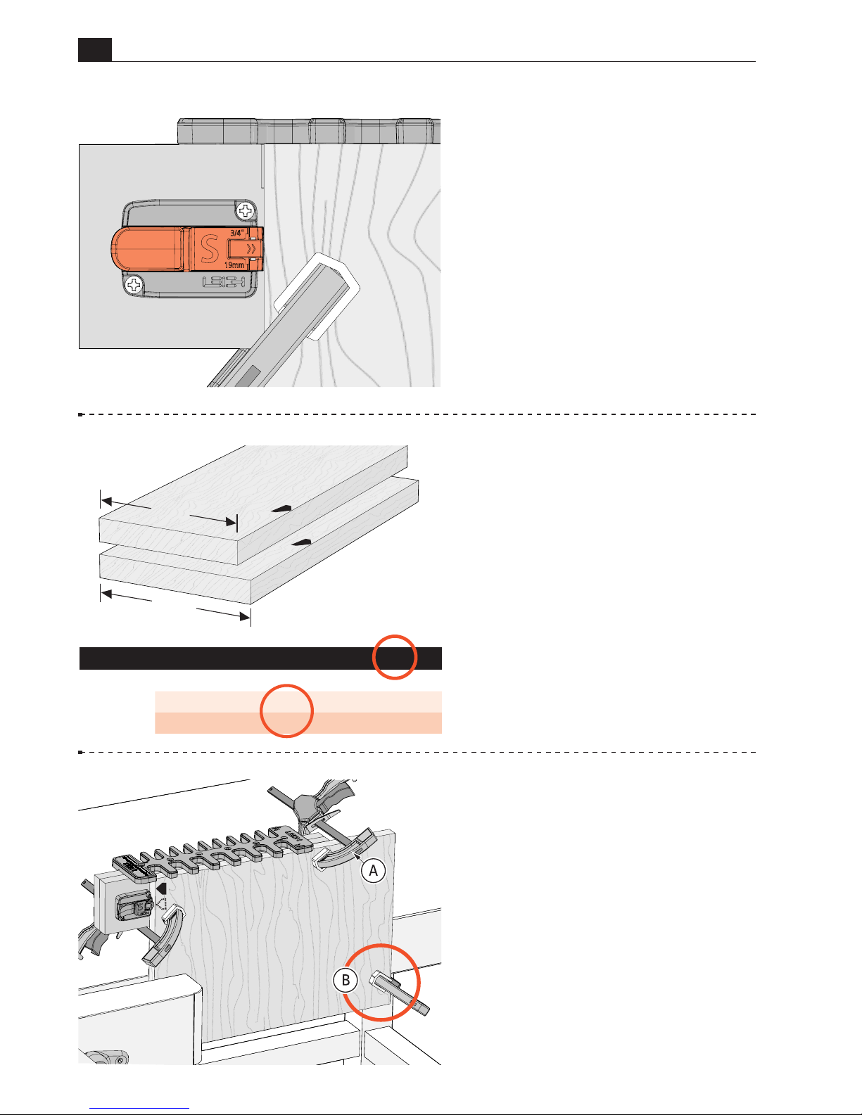
40
B975 User Guide
Chapter 6 Routing Wider Boards
6-
8
Slide the socket board stop until
it touches the edge of the board and
lock in place. The side stop is now
set.
Remove the jig from the narrow
board, and remove the board from
the vice.
6-10
Routing the Socket Board
Clamp the wide socket board in the
vice. Make sure the right hand clamp
A
will not interfere with the router.
Wide and heavy boards should be
secured with an extra clamp B, or
supported from the bottom.
S
4-3/4"
5-3/16"
Symmetrical Board Widths for
¾
"
Box Joints on Wider Boards*
Total Pins & Sockets
3 5 7 9 11 13 15 17 19 21 23
Inches 2 /" 3 /" 5 /" 6 /" 8 /" 9 /" 11 /" 12 /" 14 / " 15 /" 17 /"
Millimeters 56 94 132 170 208 246 284 322 360 398 437
6-9
Boards Widths Less Than
the Chart Width
For example:
If the chart width is
17-3/16"[437mm] and your board
width is 16-3/4"[425mm], the
difference is 7/16"[11mm]. Select a
narrow board width from the chart,
in this case 5-3/16"[132mm], and
reduce its width by the difference,
7/16"[11mm]. The narrower board
width is now 4-3/4"[121mm]. Cut
a board to that width and use the
narrow board for step 6-7.
Page 41
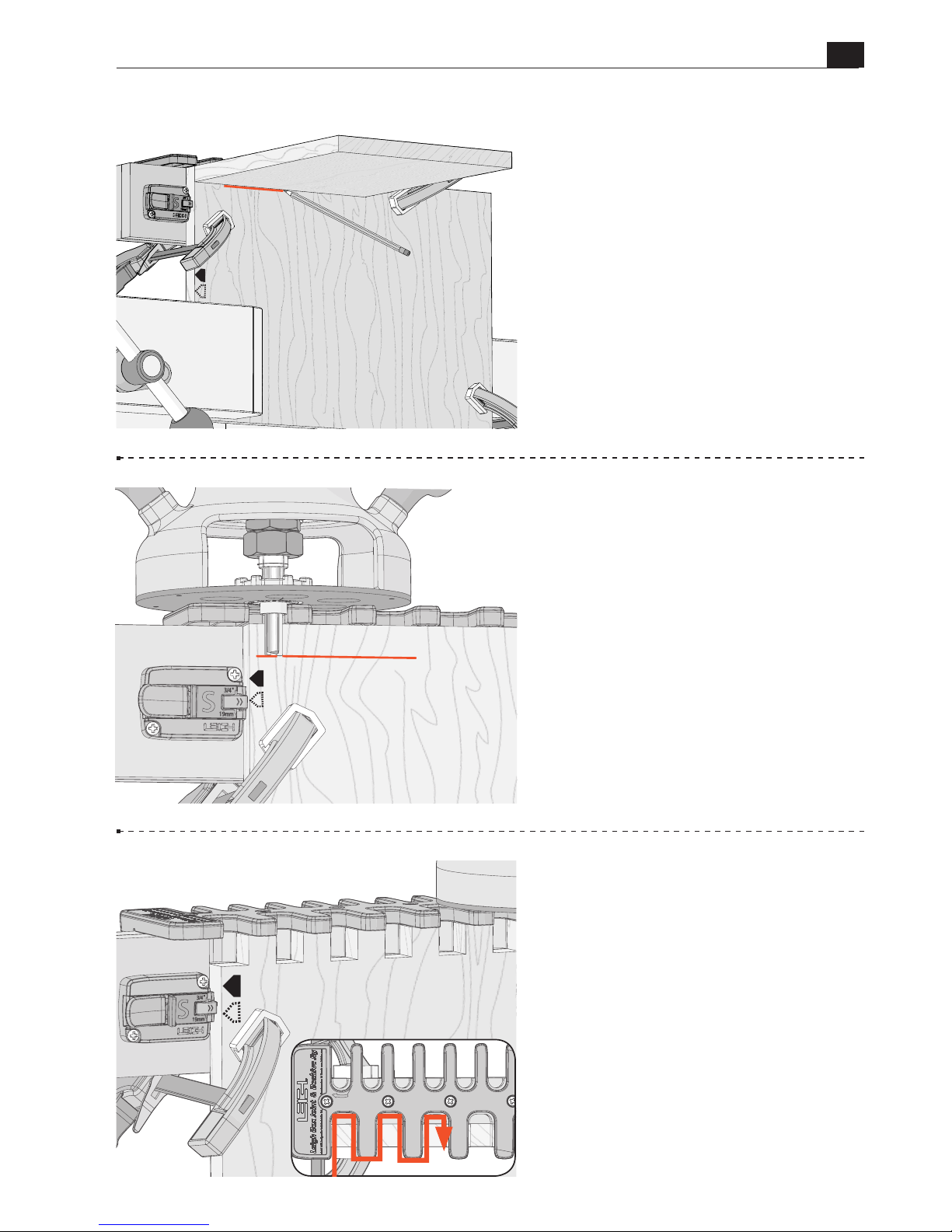
B975 User Guide
Chapter 6 Routing Wider Boards
41
6-11 Set the depth of cut using a
board the same thickness as the pin
board, in this case 3/4". Holding the
board flush under the template, draw
a line on the socket board.
6-12 Place the router on the jig and
adjust the tip of the bit up or down
until it’s at the center of the line.
Rotate the bit and collet to ensure
it spins freely and does not contact
the eBush.
6-13
Now, hold the router firmly,
as you rout straight in and out of all
template openings.
Do not rotate the router.
Be sure the e10 touches the left side
of the template opening on the way
in, and the right side on the way out.
Do not remove the jig from the
board.
S
S
S
Page 42
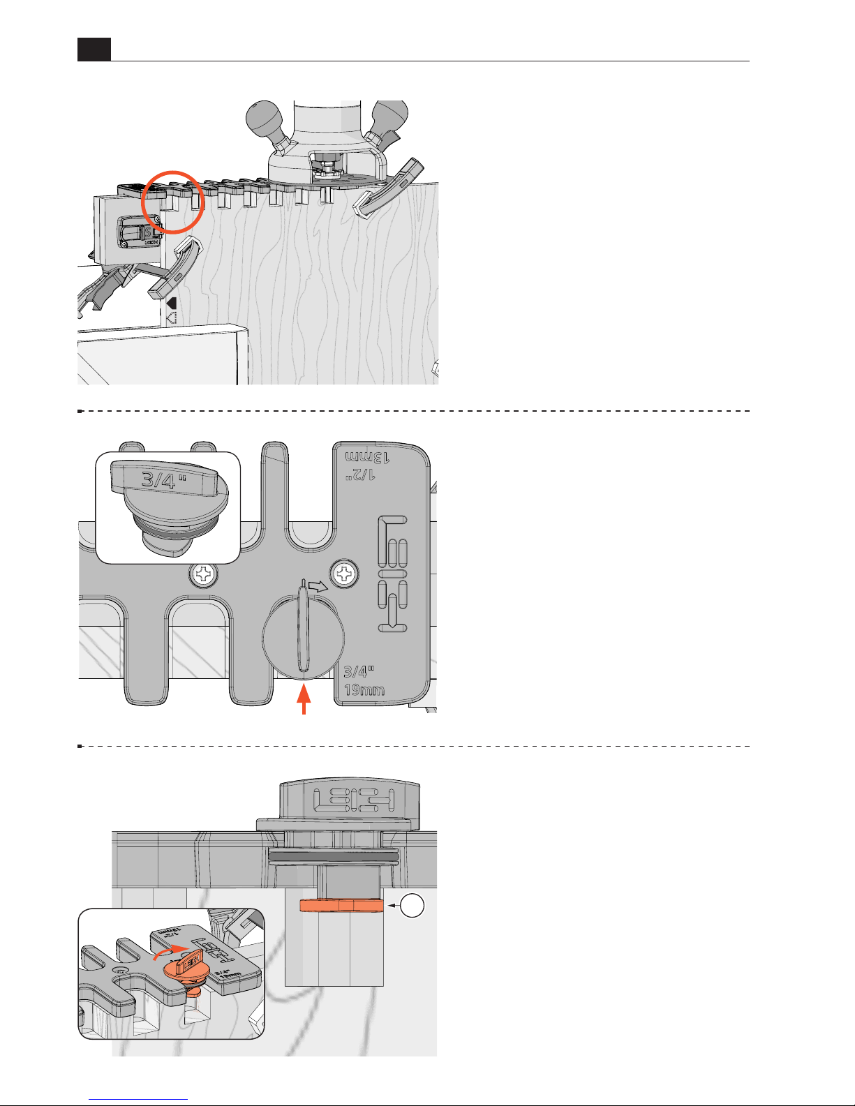
42
B975 User Guide
Chapter 6 Routing Wider Boards
A
6-14 There will now be sockets
on the left side of the board.
The remaining part of the board is
routed next, but first...
6-15 ...point the tip of the 3/4" cam
to the back of the jig and insert it in the
extreme right hand template opening.
6-16 Turn the cam clockwise
until the bottom part of the cam A
touches the right side of the last
routed opening of the board.
Leave the cam in place.
S
Page 43
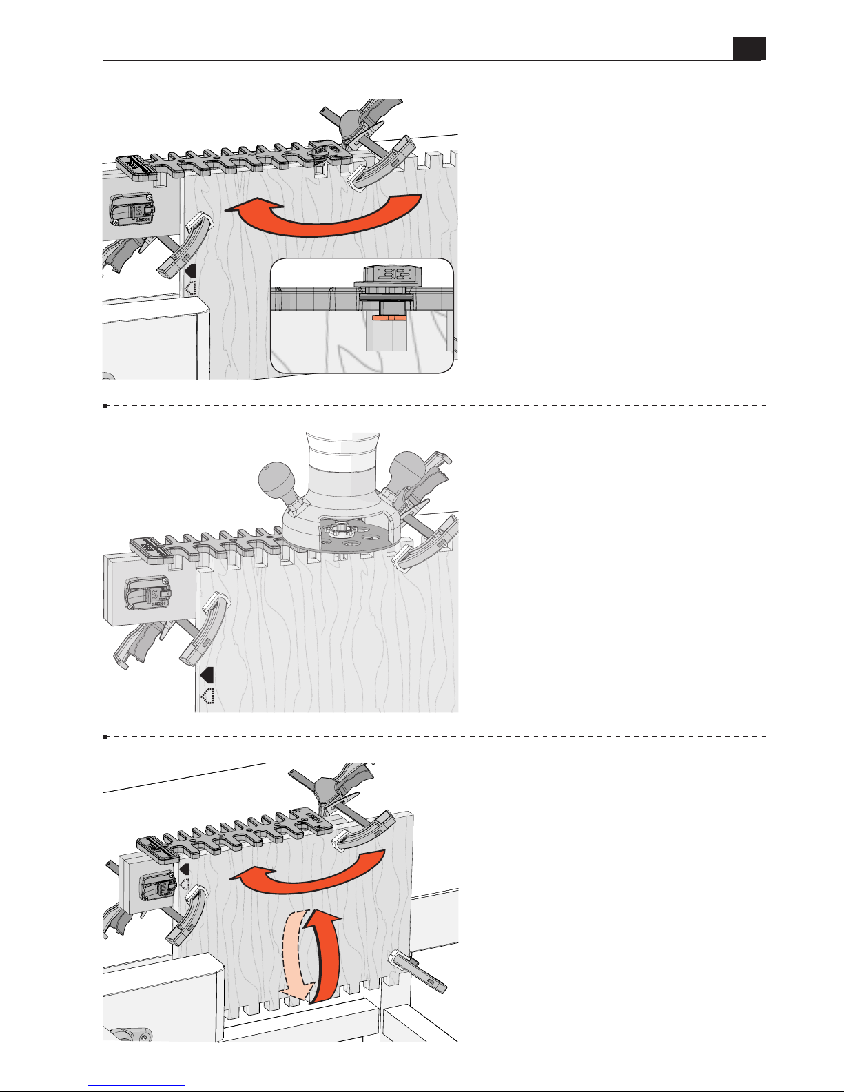
B975 User Guide
Chapter 6 Routing Wider Boards
43
6-17 Unclamp the jig, flip the
board horizontally, and re-clamp in
the vice.
Position the jig on the board so the
right edge of the cam just touches the
inside right edge of the last routed
opening. Clamp the jig in place
making sure the right hand clamp
will not interfere with the router.
Remove the cam.
6-18 Rout the remaining part of
the socket board. Remove the jig
from the board and unclamp the
board from the vice.
6-19 To rout the other end of
the socket board, turn the board
horizontally and flip it end for end,
and re-clamp in the vice. Place the
jig on the board with the side stop
against the left board edge.
If you’re making a box, rout a second
socket board.
Page 44
44
B975 User Guide
Chapter 6 Routing Wider Boards
6-20 Routing the Pin Board
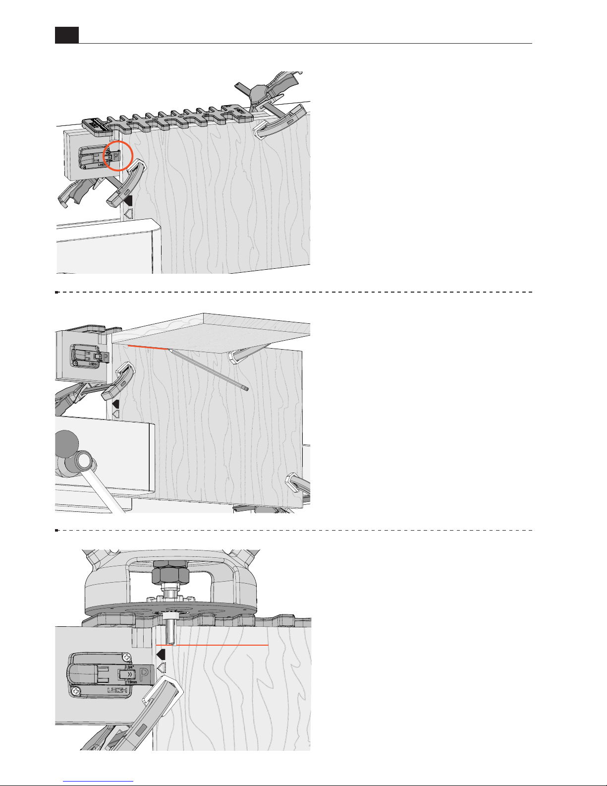
Flip the pin board stop to the P
position. Place the jig on the board
and slide it to the right until the
left edge of the board touches the
pin board stop. Clamp the board in
place.
6-21 Socket and pin boards can be
different thicknesses. Hold a board
of the same thickness as the socket
board, flush under the template, and
draw a line on the socket board to
indicate depth of cut.
6-22 Place the router on the jig and
adjust the tip of the bit up or down
until it’s at the center of the line.
Rotate the bit and collet to ensure
it spins freely and does not contact
the eBush.
P
P
P
Page 45
B975 User Guide
Chapter 6 Routing Wider Boards
45
6-23
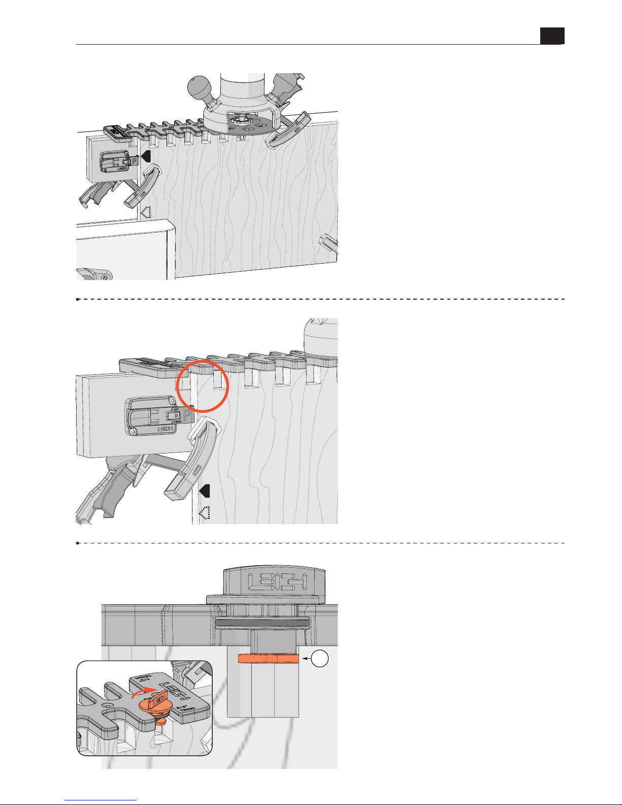
Now, hold the router firmly,
as you rout straight in and out of
each template opening. Be sure the
e10 guide bushing touches the left
side of the template opening on the
way in, and the right side on the way
out.
Do not remove the jig from the
board.
6-24
There will now be pins on the
left side of the board. The remaining
part of the board is routed next, but
first...
6-25 ...point the tip of the 3/4" cam
to the back of the jig and insert it
in the extreme right hand template
opening.
Turn the cam clockwise until the
bottom part of the cam A touches
the right side of the last routed
opening of the board.
Leave the cam in place.
P
P
A
Page 46
46
B975 User Guide
Chapter 6 Routing Wider Boards
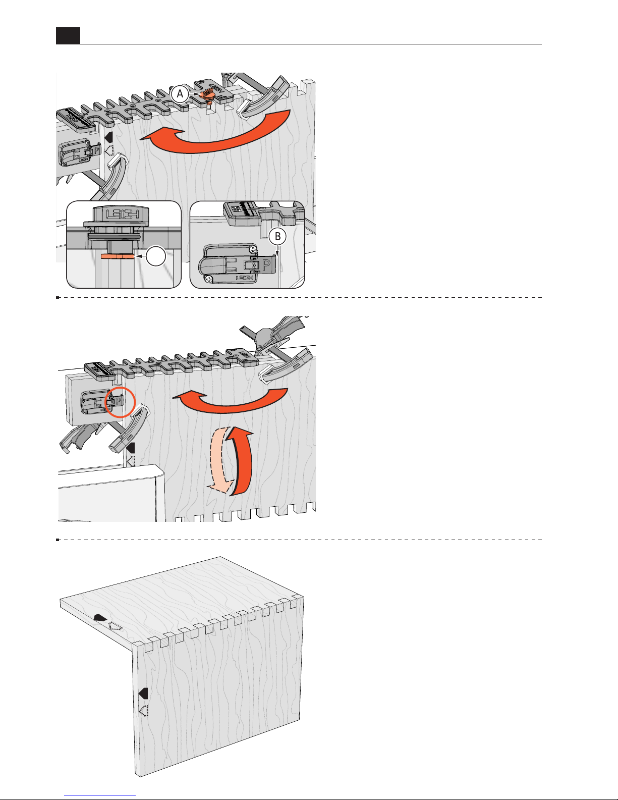
6-26 Unclamp and flip the board
horizontally. Re-clamp in the vice.
The stepover cam A, not the side
stop, is used to position the jig on the
board. There will be a small gap B
between the side stop and the board.
Place the jig on the board with the
edge of the cam just touching the
inside right edge A of the last routed
opening of the pin board. Clamp the
jig in place. Rout the rest of the pin
board.
6-27 Remove the jig and unclamp
the board from the vice.
To rout the other end of the pin
board, turn the board horizontally
and flip it end for end, and re-clamp.
Place the jig on the board with the
side stop against the left board edge.
If you’re making a box, rout a second
pin board.
6-28 Assemble the joint, keeping
the marked board edges aligned.
■
A
P
S
Page 47
47
B975 User Guide
CHAPTER 7
Router Table
Operation
This chapter assumes you have set up your
jig following the Mounting & Assembly
instructions in Chapter 4, Steps 4-17 to
4-22. You should also be familiar with all
procedures in this user guide.
IMPORTANT SAFETY NOTE
Before using your Leigh B975, you must
have completed the preparatory steps
listed in the previous pages, including
reading the jig safety recommendations
in Chapter 2.
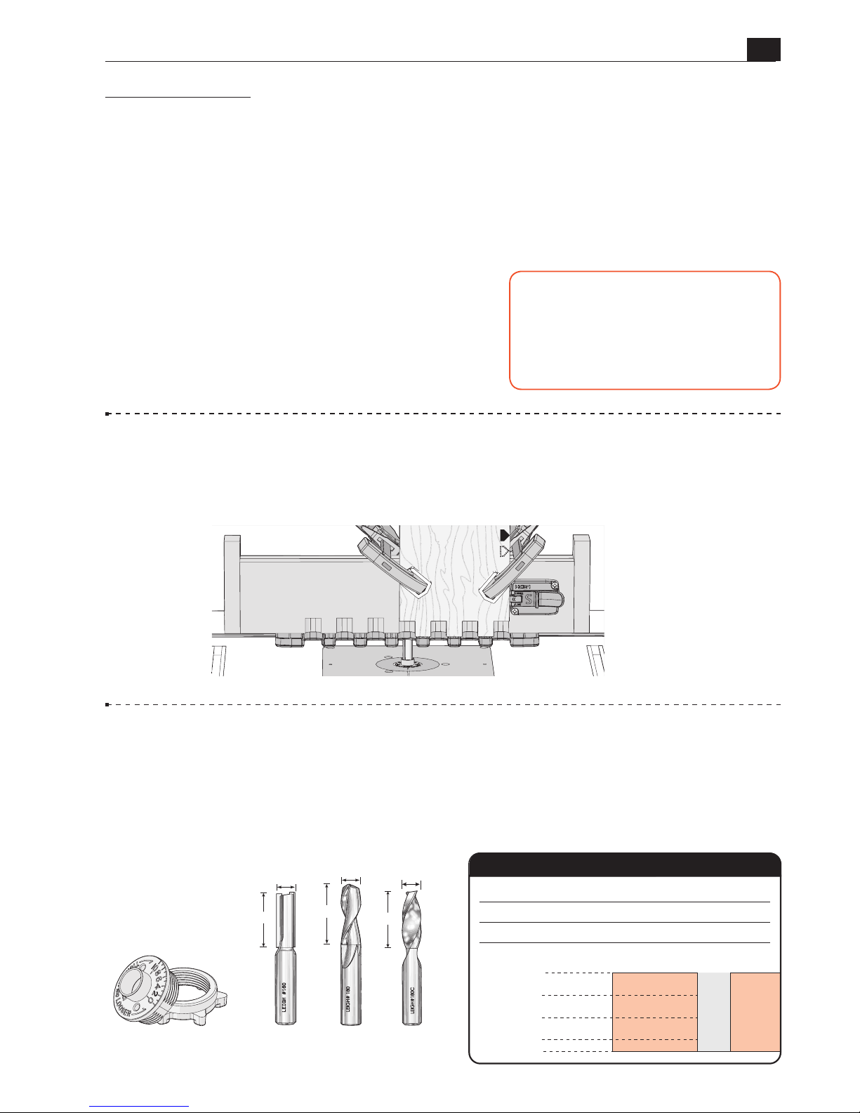
7-1 Getting Started The B975 can be used to rout box joints on a router table, on
boards up to a maximum width of 9-11/16"[246mm]. This example uses 3/4" box joints
on 3/4" thick boards. Procedures for routing 1/2" and 3/4" joints are identical.
7-2
Parts Required 3/4" and 1/2" box joints are routed with the included Leigh
No.160 1/2" straight bit and the Leigh e10 guide bushing (eBush).
No other bit diameter
and guide bushing combination may be used.
Maximum board thickness for both
joint sizes is 13/16"[20.6mm]. Depth of cut can be increased beyond the board thickness
for raised joints. Note: Optional 1/2" diameter spiral upcut bits may also be used.
S
1/2"
1/2"
1/4"
3/4"
0"
13/16"
160
180
Depth of Cut
Item No. Carbide Tipped
Bit Diameter
Item No.
Spiral HSS (Optional)
Item No. Spiral Solid Carbide (Optional)
180C
Bit Cutting Depth
160
(included)
e10
Guide Bushing
180 180C
(Optional Bits)
1-1/4"
1/2"
1/2"
1-3/4"
1/2"
1-5/8"
Page 48
B975 User Guide
Chapter 7 Router Table Operation
48
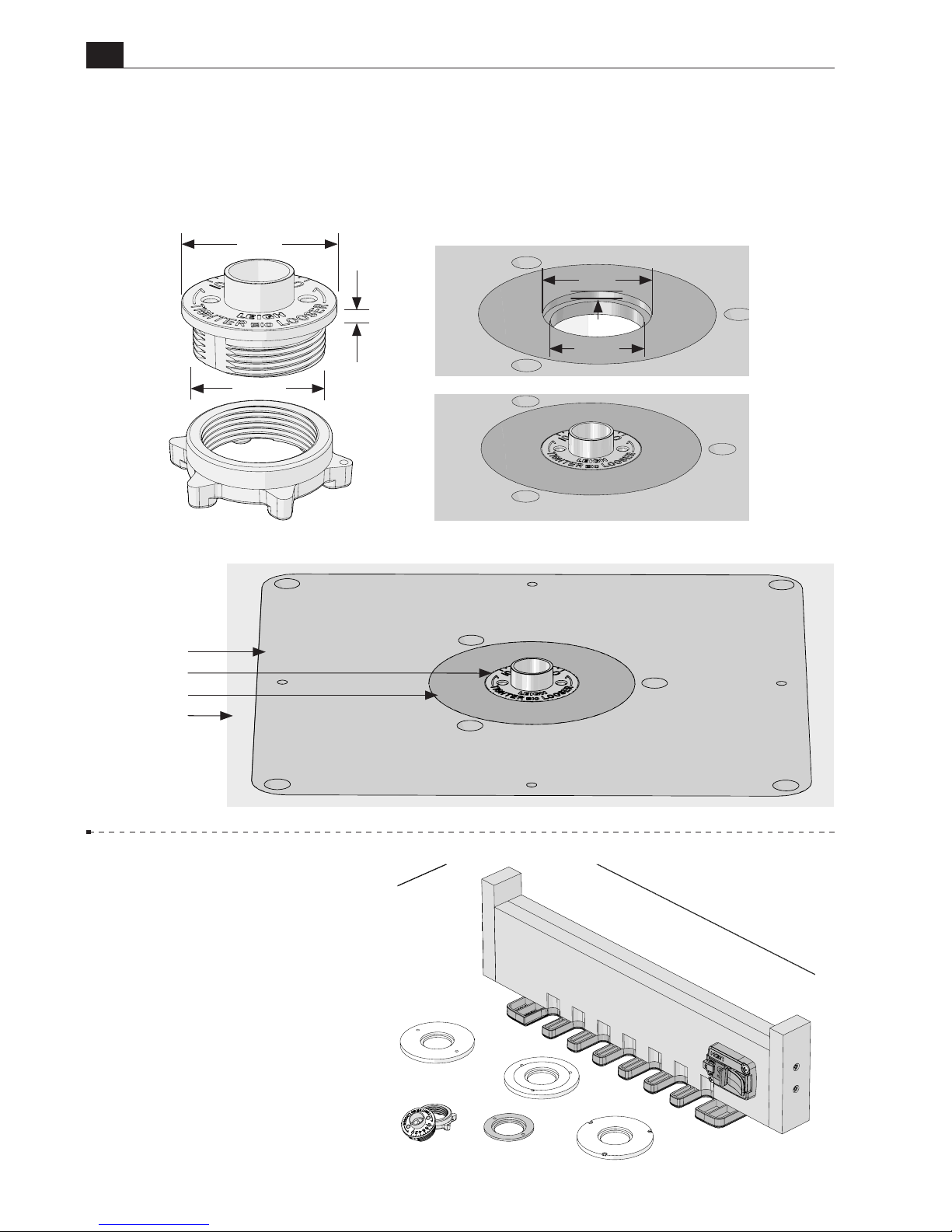
7-3 Router Table Requirements Router tables are typically used with a bearing or
fence, however, the Leigh B975 is guided around a guide bushing mounted in the router
table. Leigh eBushes (guide bushings) are designed around the 1-3/8" diameter industry
standard. See specifications below.
Leigh eBush and Nut
Router Table
eBush
Insert Ring
Insert Plate
7-4 Insert Ring To install
the eBush to your router table
insert plate, you may need a
1-3/8" diameter counter bore
insert ring. Check with your
router table or insert plate (router
lift) manufacturer, as to what
adaptation, if any, is required.
1
3
/16"
0.100"
1
3
/8"
1
3
/8"
1
3
/16"
0.100"
Page 49
B975 User Guide
Chapter 7 Router Table Operation
49
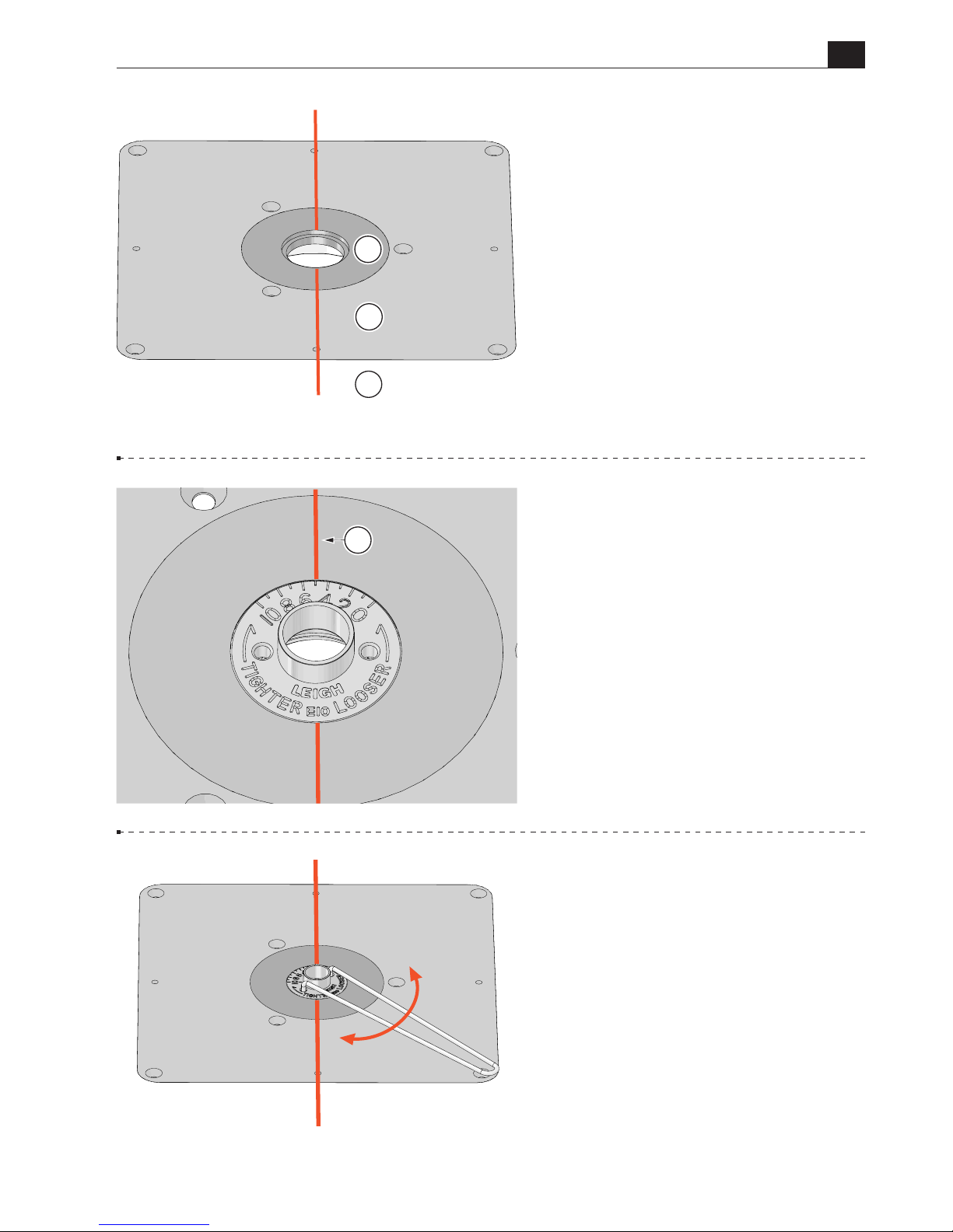
A
7-6 Install the e10 guide bushing
in the router table. Turn the e10 to
align the 5 position with the line A
you’ve just drawn.
Using an initial setting of 5 allows
adjustment for a looser or tighter
joint fit. This line will also help you
guide the jig.
C
A
B
7-5
Draw a reference line with a
permament pen on the router table,
centered on the guide bushing
opening at 12 o’clock and 6 o’clock
(shown in red for clarity only).
This will ensure correct orientation
of the eBush to the insert ring A,
the insert plate B, and the router
table C.
7-7
eBush adjustments are made
with the included pin wrench.
Markings on the eBush indicate
which way to turn it for a looser or
tighter fit. See Chapter 3.
Remember, every time you adjust
the eBush you must re-tighten the
eBush nut.
Page 50
B975 User Guide
Chapter 7 Router Table Operation
50
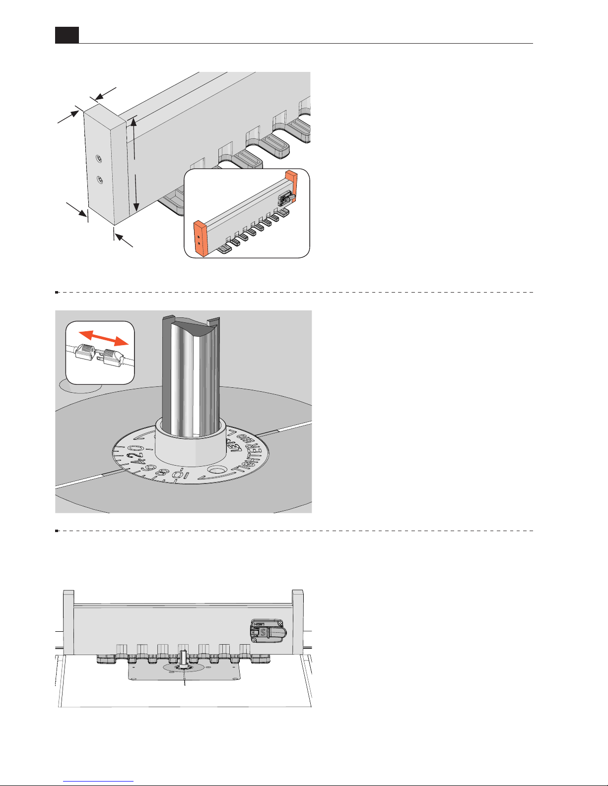
1-1/2"
4-1/2"
3/4"
7-8
Before using the jig on a router
table, handles must be attached to the
ends of the beam. Cut two pieces of
wood to the dimensions indicated
and attach with screws.
The handles will keep your fingers
safely away from the bit and help
control the jig during routing.
7-9 With the router unplugged,
install the No.160 straight bit to the
router and tighten the collet nut.
Be sure the bit spins freely
within the guide bushing before
reconnecting the power.
7-10 Reminder: If you haven’t
already done so, you must rout
grooves on each side of the beam
(see Chapter 4, steps 4-17 to 4-22).
Page 51
B975 User Guide
Chapter 7 Router Table Operation
51
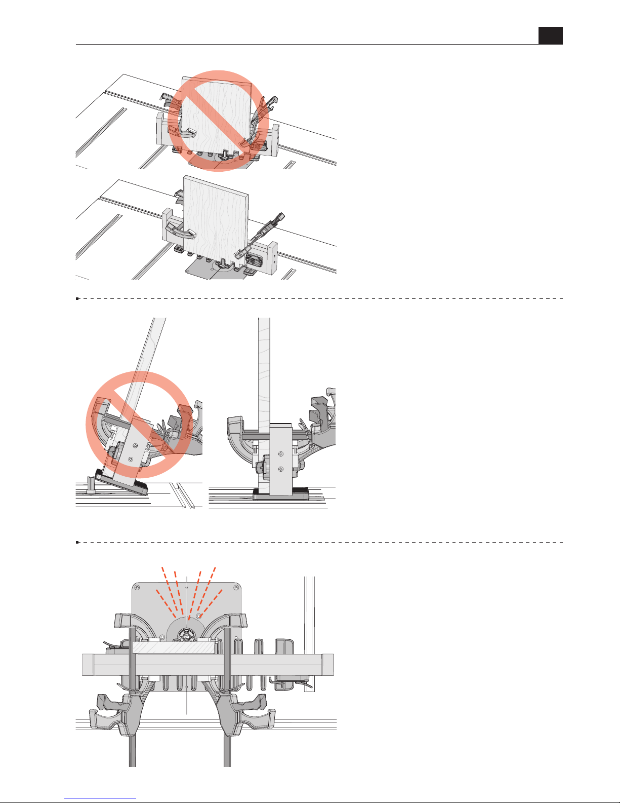
7-11 Do not turn or rotate the jig
as you rout. Keep the jig parallel to
the router table and go straight in and
straight out of each template opening.
7-12 Never tilt the jig. Keep the jig
flat on the router table at all times.
7-13
Chips and sawdust are thrown
out at high speed. Always stand
and use the jig away from chip and
sawdust ejection.
Operator’s
Position
Page 52
B975 User Guide
Chapter 7 Router Table Operation
52
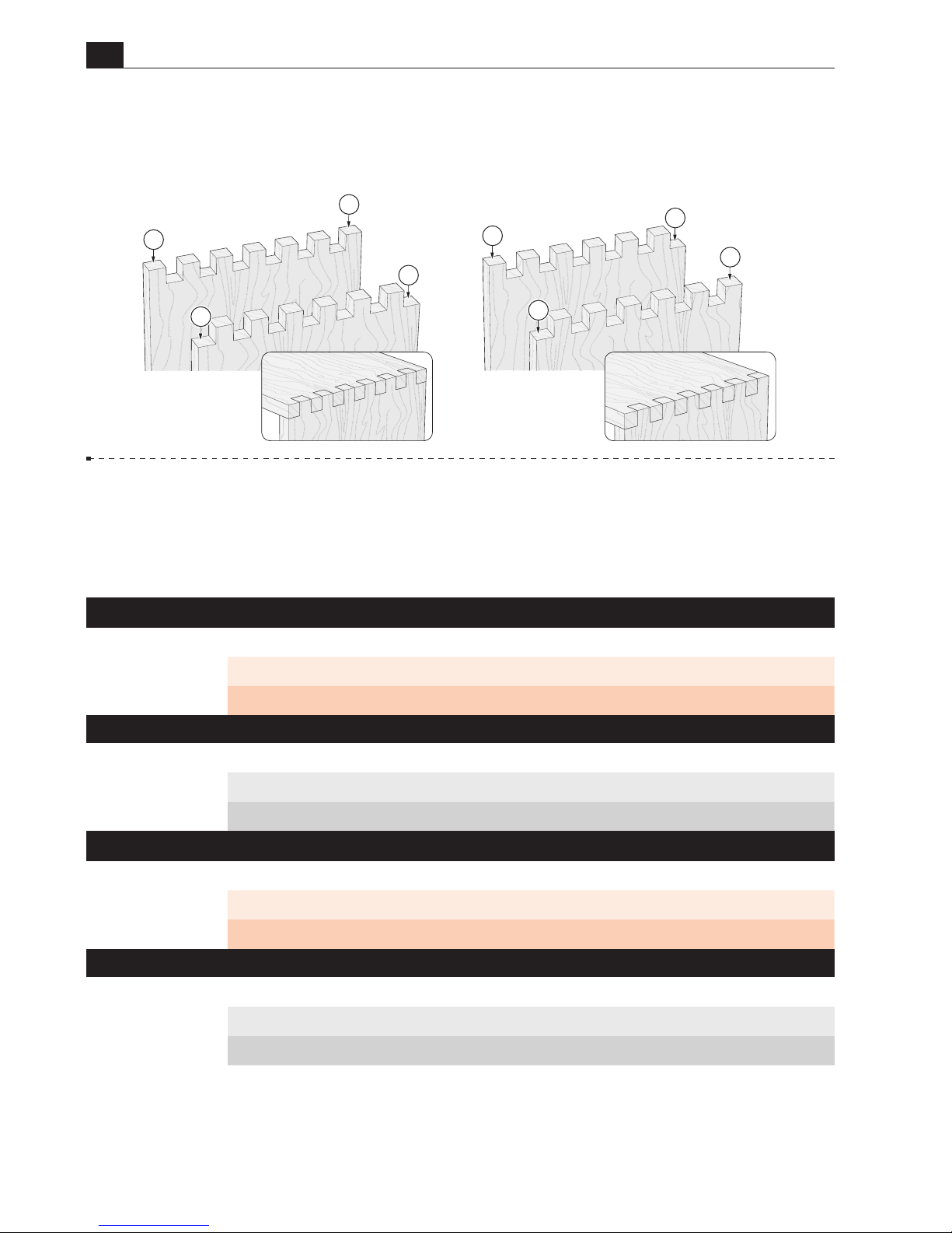
7-14 Joint layout
Symmetrical joints have pins
A
on both edges of the pin board, and
sockets
B
on both edges of the socket board. Asymmetrical joints have a socket Con one
edge and a pin Don the other edge of each board.
7-15
Board Width Selection
Board widths are determined by the total number of pins
and sockets in the joint design and whether the joint is symmetrical or asymmetrical. Use this
chart to determine board widths up to
9-11/16"[246 mm]
.
Symmetrical Board Widths for
¾
"
Box Joints
Total Pins & Sockets
3 5 7 9 11 13
Inches 2 /" 3 /" 5 /" 6 /" 8 /" 9 /"
Millimeters 56 94 132 170 208 246
Asymmetrical Board Widths for
½
"
Box Joints
Total Pins & Sockets
4 6 8 10 12 14 16 18
Inches 1 /" 3" 4" 5 /" 6 /" 7 /" 8 /" 9 /"
Millimeters 50 76 102 128 154 180 206 232
Asymmetrical Board Widths for
¾
"
Box Joints
Total Pins & Sockets
4 6 8 10 12
Inches 2 /" 4 /" 5 / " 7 /" 8 /"
Millimeters 75 113 151 189 227
Symmetrical Board Widths for
½
"
Box Joints
Total Pins & Sockets
3 5 7 9 11 13 15 17 19
Inches 1 /" 2 /" 3 /" 4 /" 5 /" 6 /" 7 /" 8 /" 9 / "
Millimeters 37 63 89 115 141 167 195 219 245
B
B
D
D
C
C
A
A
Asymmetrical
Symmetrical
Socket Board
Pin Board
Socket Board
Pin Board
Page 53
B975 User Guide
Chapter 7 Router Table Operation
53
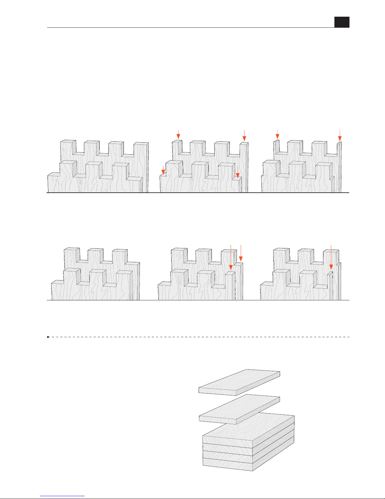
7-16 Board widths indicated in the chart on the previous page will produce full size pins and
sockets at each board edge, for symmetrical or asymmetrical joints. Symmetrical joint board
widths may be reduced as required, resulting in smaller but equally sized pins and sockets at
each board edge. If board widths are reduced for asymmetrical joints, one edge of the board will
have a full size pin and socket while the other board edge will have a smaller pin and socket.
This may result in an unattractive joint.
7-17 Making a Box
Prepare four similar boards 3/4" thick
× 5-3/16" wide by about 12" long
[19mm×133mm×305mm], and two test
boards, 3/4" thick by about 4"[100mm]
wide.
Note:
Boards of different thicknesses may
also be joined.
IMPORTANT:
Read the whole chapter before routing any boards.
Symmetrical
Asymmetrical
Full size
pins and sockets
Full size
pins and sockets
When a symmetrical board width is reduced,
the joint will have smaller, but equal sized
pins and sockets at each edge of the board.
Width specified in the board width chart
results in full size pins and sockets at each
edge of the board.
Width specified in the board width chart
results in a full size pin at one edge of the
board, and a full size socket at the other edge
of the board.
When an asymmetric board width is reduced,
the joint will have a full size pin and socket at
one edge of the board, and a reduced size pin
and socket at the other edge of the board.
When the board width is reduced further,
the result is very narrow and fragile pins at
each edge of the board.
When the board width is reduced further,
the result is a very narrow and fragile pin at
one edge of the board.
Small pin
can break easily
Reduced size
pin and socket
Small pins can break easily
Reduced size pins and sockets
Page 54
B975 User Guide
Chapter 7 Router Table Operation
54
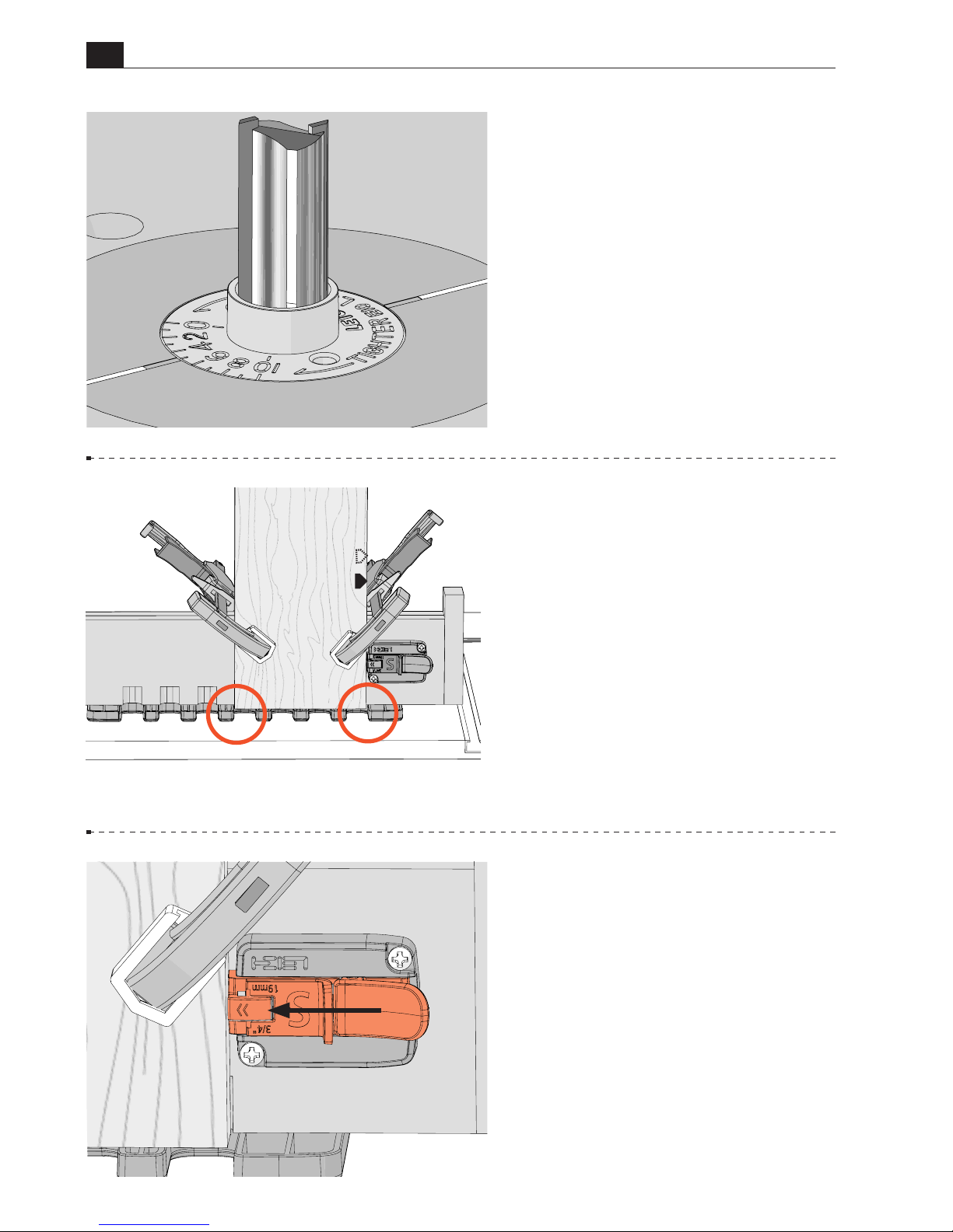
7-18 Routing a Test Joint Test
joints are routed with the eBush
set at the 5 position. Tighten the
eBush nut after each guide bushing
adjustment.
7-19
Center a test board on the left
side of the 3/4" template, leaving an
equal amount overhang on each edge
of the board.
Clamp the board in place.
7-20 Slide the socket board stop
until it touches the edge of the board.
Secure the side stop with the thumb
lock.
Page 55
B975 User Guide
Chapter 7 Router Table Operation
55
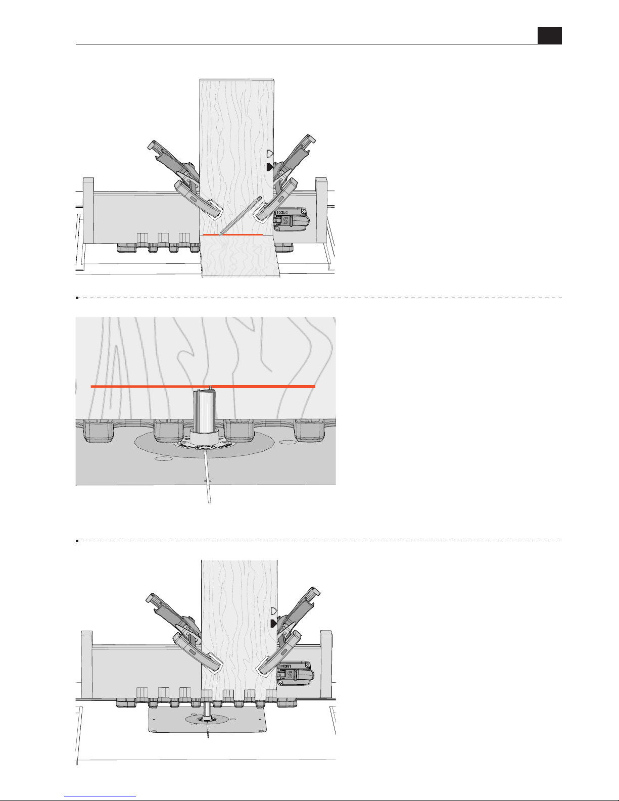
7-21 Socket and pin boards may
differ in thickness. Always use
the mating pin or socket board to
determine the depth of cut. In this
case, hold a pin board flush against
the template and draw a line on the
board, indicating depth of cut.
7-22 Place the router on the jig and
adjust the tip of the bit up or down
until it’s at the center of the line.
Rotate the bit and collet to ensure
it spins freely and does not contact
the eBush.
7-23 Rout straight in and out of
each template opening. Be sure the
e10 guide bushing touches the left
side of each template opening on the
way in, and the right side on the way
out. Do not rotate the jig.
Chips and sawdust can accumulate
between the template openings.
Check each routed slot to ensure it
has been routed completely. Remove
the board.
Page 56
B975 User Guide
Chapter 7 Router Table Operation
56
7-24 Place the second test board
against the side stop and clamp in
place. Rout the board.
35
TOO LOOSE
TIGHTEN
TOO TIGHT
LOOSEN
7-25 Joint Fit Adjustment
Assemble the test boards. If the joint
is too loose, use the pin wrench and
turn the eBush to a higher number
and rout two fresh board ends.
If the joint is too tight, turn the
eBush to a lower number and rout
two fresh board ends.
Re-tighten the eBush nut after
each guide bushing adjustment.
7-26 Each increment on the
eBush changes the joint glue line
fit by 0.002"[0.05mm]. Half an
increment, a mere 0.001"!
Page 57
B975 User Guide
Chapter 7 Router Table Operation
57
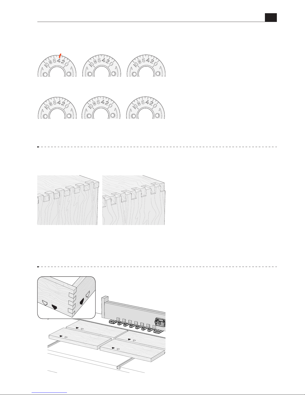
7-27 Use these eBush diagrams
to record the settings you used to
achieve perfect joint fit. The first
eBush is an example of how to record
your setting.
OVER FLUSH UNDER FLUSH
7-28
Joint flushness is determined
by the depth of cut.
If the joint is over flush, lower the bit
to make a shallower cut.
If the joint is under flush, raise the
bit to make a deeper cut.
Rout new test joints until fit and
flushness are perfect before routing
the final boards.
7-29 Making a Box
Lay out the four boards and mark
two pin boards and two socket
boards. Also, indicate the common
board edges that will go against the
side stop.
SAMPLE
June7, 1/2"joint
Maple, 160 bit
P
S
S
P
P
S
Page 58
B975 User Guide
Chapter 7 Router Table Operation
58
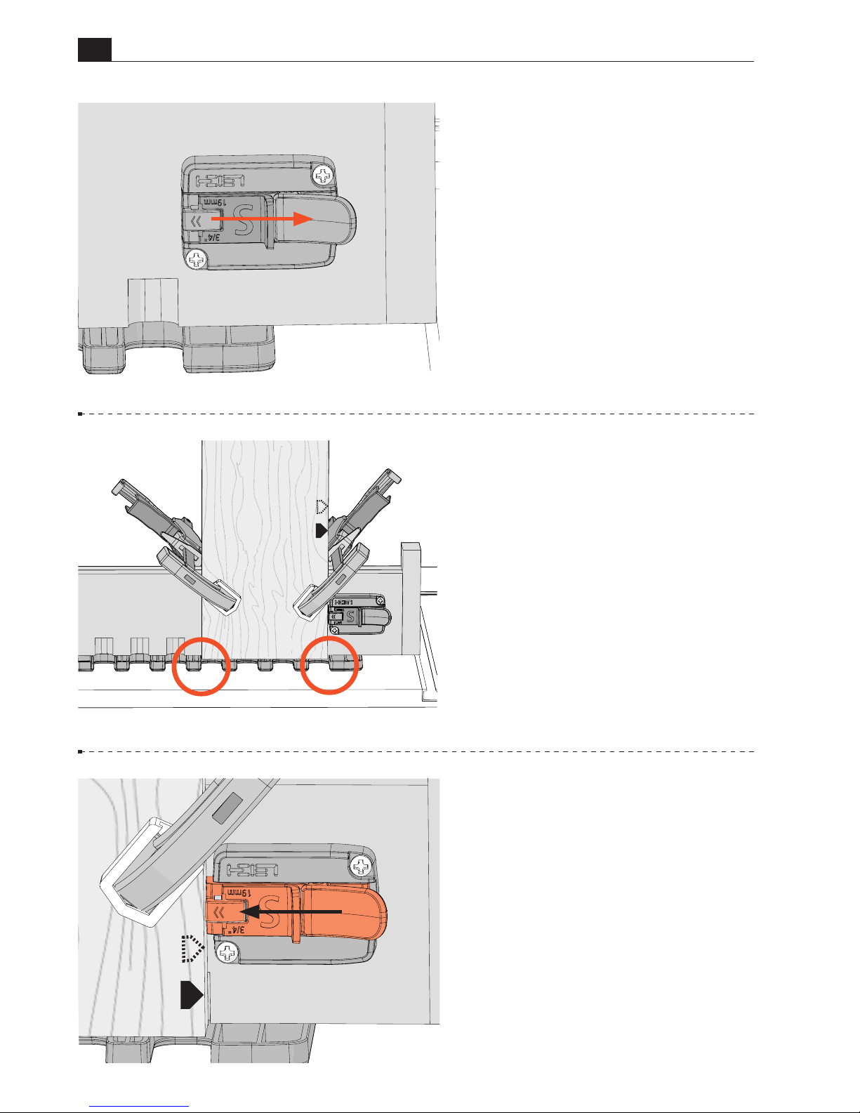
7-30 Before clamping the first
socket board, ensure the socket board
stop is fully retracted, and locked in
place.
7-31 With the left edge of the board
in the first template opening, position
the socket board on the jig, leaving
equal amounts of the board showing
at each edge.
Clamp the jig in place.
7-32 Slide the socket board stop
until it touches the edge of the board,
and secure with the thumb lock.
The side stop remains locked in place
for all socket and pin board routing.
S
Page 59
B975 User Guide
Chapter 7 Router Table Operation
59
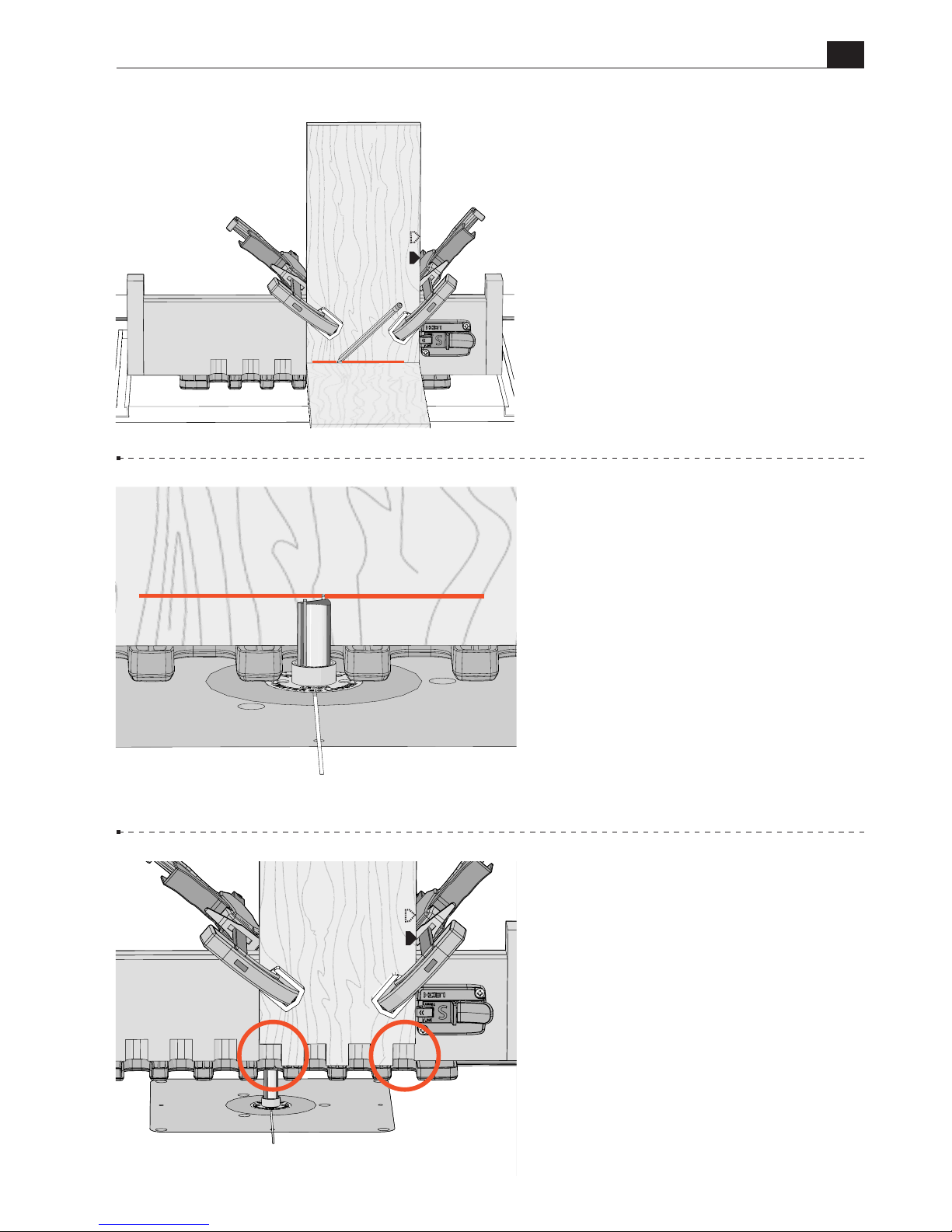
7-35 Rout straight in and out of
each template opening. Be sure the
e10 guide bushing touches the left
side of the template opening on the
way in, and the right side on the way
out. Do not rotate the jig.
There will now be a full socket at
each edge of the board.
7-33
Hold a pin board flush against
the template and draw a line on the
board, indicating depth of cut.
7-34 Adjust the tip of the bit up or
down until it’s at the center of the
line.
S
S
Page 60
B975 User Guide
Chapter 7 Router Table Operation
60
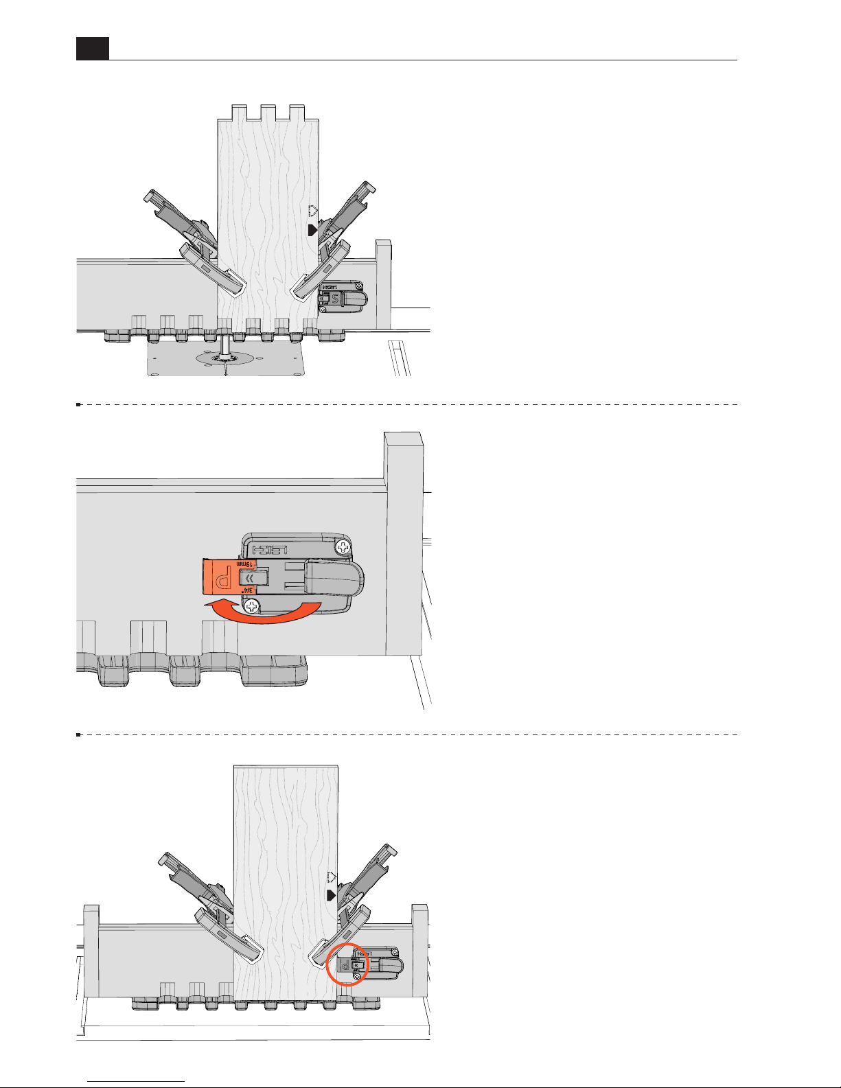
7-36 Unclamp and flip the first
socket board end for end, keeping
the same board edge against the side
stop, and clamp in place. Rout in
each template opening.
Repeat the procedure for the second
socket board.
7-37 Routing the Pin Board
Flip the side stop to the pin board
stop position.
7-38 Place the first pin board on
the jig with its edge touching the pin
board stop and clamp in place.
S
P
Page 61
B975 User Guide
Chapter 7 Router Table Operation
61
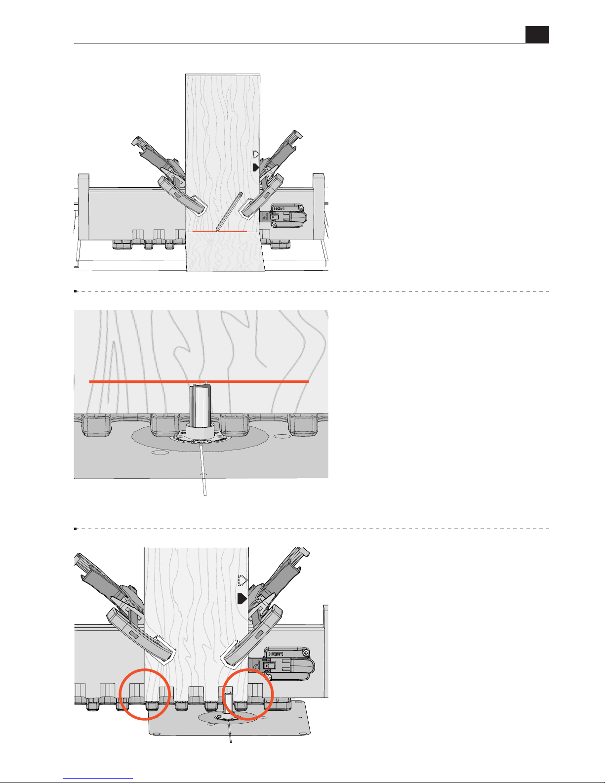
7-41 Rout straight in and out of
each template opening. Be sure
the e10 touches the left side of the
template opening on the way in, and
the right side on the way out.
Do not
rotate the jig.
There will now be a full pin at each
edge of the board.
7-40 Adjust the tip of the bit up or
down until it’s at the center of the
line.
7-39 Hold a socket board flush
against the template and draw a line
on the board, indicating depth of
cut.
P
P
Page 62
B975 User Guide
Chapter 7 Router Table Operation
62
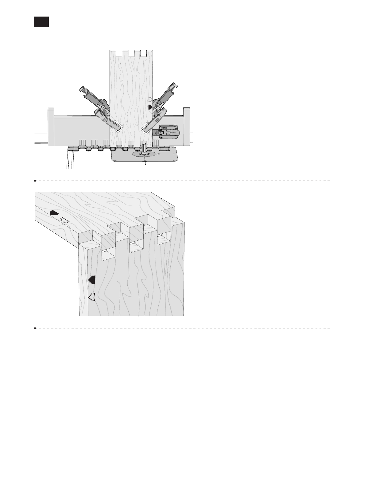
7-43 Remove the board from the
jig and assemble the joint, keeping
the marked board edges aligned. ■
7-42 Unclamp and flip the first
pin board end for end, keeping the
same board edge against the side
stop, and clamp in place. Rout in
each template opening.
Repeat the procedure for the second
pin board.
P
S
P
Page 63
63
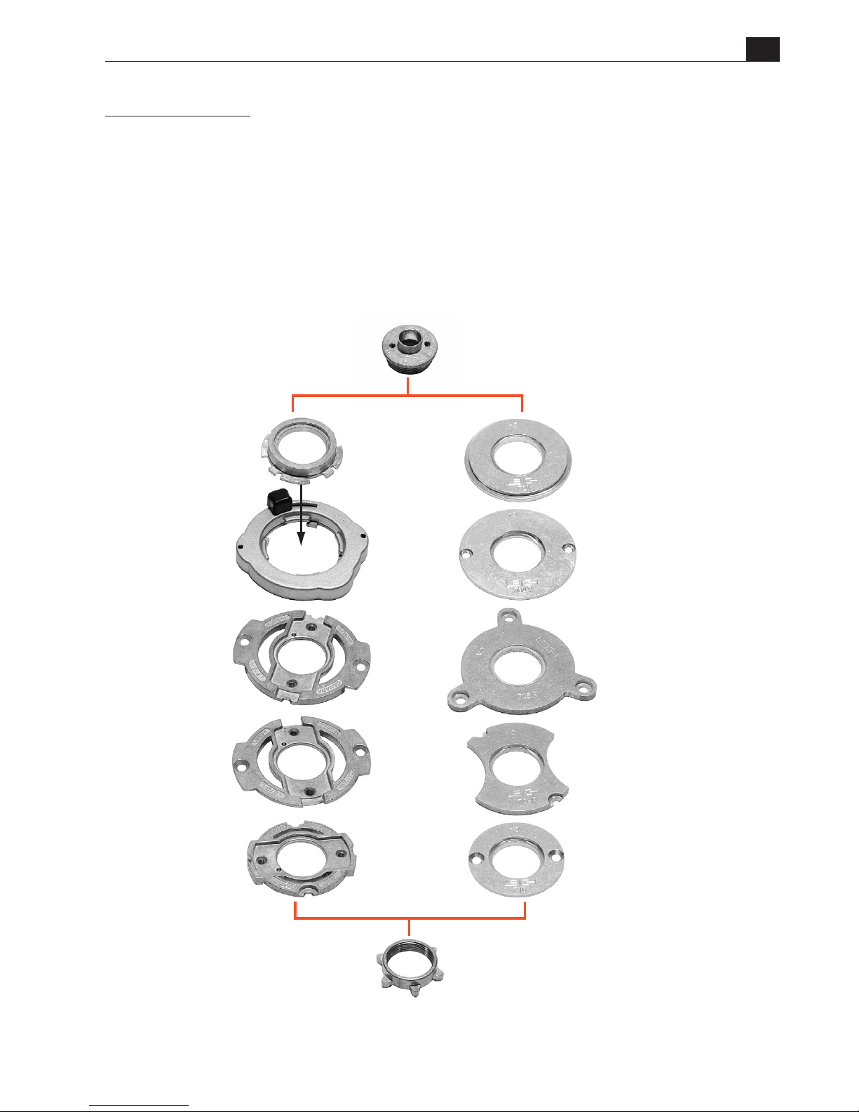
e10
eBush
Nut for
e10 eBush
703
702R
706R
705R
710
721
RA1100
RA1126
704R
702
RA1129
Set includes Bosch
Adapter RA1100
and its holder
Bosch RA1126
}
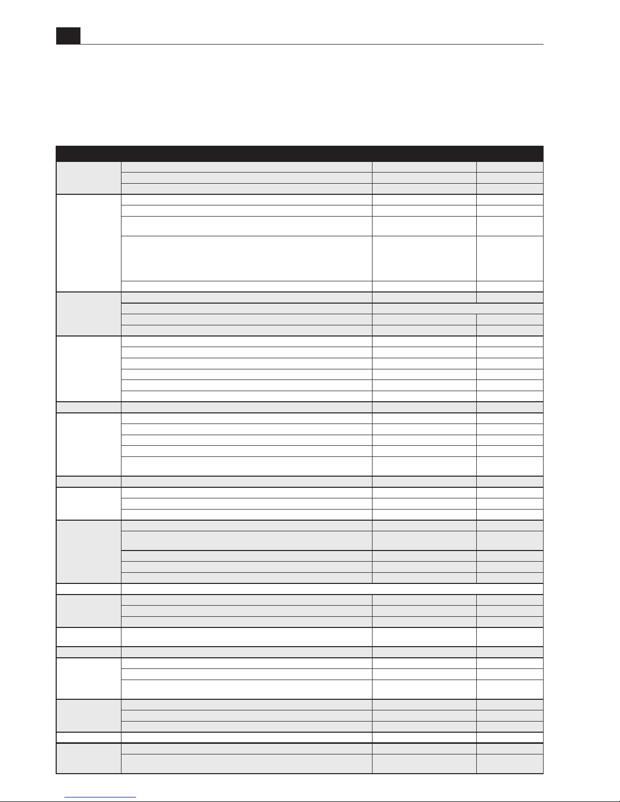
The B975 requires a router fitted with the e10 guide bushing, and possibly an adapter
to fit the bushing to the router. Leigh offers the following guide bushing adapters that fit
many common routers.
See the list of routers in the chart on the next page. For a complete list of routers see
www.leighjigs.com.
FOR HAND HELD ROUTERS ONLY
B975 User Guide
CHAPTER 8
Guide Bushing Adapter Selection
Page 64
64
64
B975 User Guide
Chapter 8 Guide Bushing Adapter Selection
1 BRAND 2 ROUTER MODEL 3 ROUTER ADAPTER 4 e10 ◆
BLACK & DECKER
All Professional, HD1250, RP400K, 7614 Not Required e10
6200 720673-00 e10
SR100, 7AEE, KW780 series, KW800, KW850 710 e10
BOSCH
90085, 90088, 90098, 90140, 90150, 90300, 90303, 90305, 91264 Aftermarket base plate required e10
1600, 1601, 1602, 1603, 1604, 1606, B1350 RA1110 e10
North American ROUTERS PRODUCED AFTER mid-2010: 1613EVS, 1613AEVS, 1617,
1617EVS, 1618, 1618EVS, 1619EVS, MR23EVS, MRC23EVS, MRF23EVS, MRP23EVS
RA1126 quick change adapter and
RA1100 bushing adapter req’d
e10
North American ROUTERS PRODUCED BEFORE mid-2010 and others available
worldwide that include the RA1126 adapter: 1613(EVS)(AEVS), 1614(EVS), 1617EVS,
1618EVS, 1619EVS, B1450, GOF900(CE)(ACE), GOF1200, GOF1250(CE)(LCE),
GOF1300(CE)(ACE), GOF1600CE, GOF2000CE, GMF1400, GMF1600CE, POF800ACE,
POF1100AE, POF1200AE, POF1400ACE
RA1100 e10
1611, 1611EVS, 1615, 1615EVS, B1550, GOF1600, GOF1700ACE 702 e10
CRAFTSMAN
(SEARS)
All non-plunge models Aftermarket base plate required e10
135275070 Plunge See Skil 1823 or 1835
Other plunge models 702 e10
MD11 Plunge & Fixed Base. MD9.5 Fixed Base Not Required e10
DEWALT
DW610, DW616, DW618 Not Required e10
DW613, DW615(UK) 710 e10
DW614, DW615, DW621, DW624, DW625, DW626 N. America Only, Supplied w/router e10
DW621K, DW622 and DW626 outside N. America 706R e10
DW625 Type 1,2,3,5 outside N. America 702 e10
DW624 & DW625 Type 4 outside N.America, DW625EK 702R e10
FEIN RT1800 Supplied w/router e10
FESTOOL
OF1E , OF2E, OF650, OF900E ,OF1000, OF1010E 704R e10
OF2000, OF2000E 705R e10
OF1400 and OF2200 North America Only Supplied w/router e10
OF1400 Outside North America 493566 e10
OF2200 Outside North America
494627 O-ring may be required
to keep bushing centered
e10
FREUD FT1700(2), FT2000, FT2200, FT3000 721 e10
HITACHI
TR8, TR12, FM8, M8, M12 Series 325211 OR 703 e10
M12VC, KM12SC, KM12VC Not Required e10
M12SA2, M12V2 325224 e10
MAKITA
M363, MRP090, RP1800(F), RP1801(F), RP2300(FC), RP2301(FC), 3612C Europe Qk Fit Base
721 e10
3600, 3606, 3608, 3612, 3612B, 3612BR, 3612C N. America, 3620, 3621, RP0900,
RP900K
703 e10
3601B 321 493-1 e10
RP0910, RP1110C 706R e10
RF1100, RF1101, RD1100, RD1101, RP1101 Not Required e10
MASTERCRAFT
Please contact Leigh for assistance
MILWAUKEE
5615, 5616, 5619 49-54-1040
(replacement base)
e10
5625 49-54-1026
(replacement base)
e10
5670 Not Required e10
PORTER CABLE
(ROCKWELL)
All Not Required or Supplied w/router e10
RIDGID R2930 (for all others, please contact Leigh for assistance) 704R e10
RYOBI
R30, R50, R150, R151, RE155, R500, R501, R502 703 e10
R600, R601, RE600, RE601 702 e10
R160, R161, R162, R163K, R165, R170,
R175, RE175, R180, R180PL, R181, R185, ERT1150
706R e10
SKIL
1823 or 1835 91803 e10
SK1810, 1815, 1820, 1825 RAS140 e10
All others Aftermarket base plate required e10
TREND T3, T4, T5, T9, T10, T11–UniBase required 710 e10
TRITON
TRC001 TGA006 or 704R e10
JOF001, MOF001, TRA001
Accessory Kit (includes adapter)
TGA001 or TGA150
e10
DIRECTIONS
A. Locate router maker and router model in Columns 1 and 2.
B. Locate adapter required for your router in Column 3.
• Order Leigh adapters (part no’s in red) in Column 3 from Leigh.
• Order Bosch adapters RA1100 and RA1126 in Column 3 from Leigh or
your Bosch dealer.
• Order all other adapters from the router manufacturer’s dealer.
Note: Adapter mounting screws are included with router.
C. Note:
◆ The
e10 elliptical guide bushing (5/8"[15.8mm]) shown
in column 4 is supplied with the B975 jig. Order only if you require a
replacement.
Adapters for Router Tables
Leigh guide bushings and eBushes are based on the industry standard 1-3/8"
2-piece design. Most router tables have adapters that accept these standard
guide bushings. If your router table does not have a suitable adapter, please
check with the router table manufacturer.
Page 65
65
Our Commitment to You Leigh Industries takes pride in its commitment to providing
excellence in customer service and support. This user guide is designed to provide you with
the answers to any questions you have. However, if you require assistance, please feel free
to contact customer service/technical support below or a distributor listed on the next page.
B975 USER GUIDE
CHAPTER 9
Customer Support
EMAIL/WEB
Customer Service
Technical Support
Website
www.leighjigs.com
Manufacturer: Canada/USA
NOTE:
Email can be useful, but technical
queries usually raise queries from us.
A phone call is the quickest and most
convenient way to get queries answered,
either directly to Leigh (toll free in North
America) or to your national distributor.
–Thanks!
TEL/FAX
Customer Service
and Technical Support
800-663-8932
(Canada/USA)
604-464-2700 (Tel.)
604 464-7404 (Fax.)
MAILING ADDRESS
Leigh Industries Ltd.
P.O. Box 357
Port Coquitlam, B.C.
Canada V3C 4K6
LOCATION
Leigh Industries Ltd.
1615 Industrial Ave.
Port Coquitlam, B.C.
Canada V3C 6M9
Distributors listed on next page.
Page 66

66
66
B975 User Guide
Chapter 9 Customer Support
AUSTRALIA & NEW ZEALAND
Maxis Distribution
128 Ingleston Rd., Wakerley, Qld., 4154
Australia
Tel: 1300 767 366
Tel (Int.): +61 7 3292 0392
Email: [email protected]
Web: www.maxis.com.au
CHINA
Harvey Industries Co., Ltd.
68-10 Suyuan Avenue
Jiangning District Nanjing 211100, China
Tel: (0)86 5792 8869 / 5792 8021
Fax: (0)86 5792 8826
Email: [email protected]
Website: www.harveyworks.cn
FRANCE
Ets Bordet
98 Rue Louis Ampère, 93330
Neuilly Sur Marne, France
Tel: 01 41 53 40 40
Email: [email protected]
Web: www.bordet.fr
GERMANY, AUSTRIA & SWITZERLAND
Hacker GmbH
Holzbearbeitungsmaschinen
Traberhofstraße 103 D-83026 Rosenheim,
Deutschland
Tel: 08031 269650
Fax: 08031 68221
Email: [email protected]
Web: www.leigh.de
ITALY
Ferrari Macchine Legno SRL
Via Gallarata 74/76/78
20019 Settimo M.se (MI) Italy
Tel: 39 02 335 010 95
Fax: 39 02 335 005 27
Email: [email protected]
Web: www.ferrarimacchine.com
JAPAN
Off Corporation Inc.
323-1 Yanbara, Shimizu-ku, Shizuoka-shi
Shizuoka-ken, Japan 424-0002
Tel: 81-50-3816-0115
Fax: 81-54-367-6515
Email: [email protected]
Web: www.off.co.jp
KOREA
Leigh Korea
665-3, Munhyung-Ri, Opo-Eup, Kwangju-Si,
12774, South Korea
Tel: 82 (0) 70-8252-0988
Fax: 82 (0) 31-765-5602
Email: [email protected]
Web: www.leigh.co.kr
NETHERLANDS, BELGIUM
& LUXEMBOURG
Houtbewerking Krielaart
9217RR Nijega, Netherlands
Tel: +31 512 354 770
Email: [email protected]
Web: www.leighjigs.nl
RUSSIA
Unicom Ltd.
Nikitskij Boulevard 12
Moscow, 119019, Russia
Tel: 7 (495) 690 0454
Email: [email protected] (Russia)
Web: www.leighjigs.ru (Russia)
SOUTH AFRICA
Hardware Centre
PO Box 4059, Randburg 2125
South Africa
Tel: +27 011 791-0844/46
Fax: +27 011 791-0850
Email: [email protected]
Web: www.hardwarecentre.co.za
SWEDEN
Toolbox Sweden AB
Bruksgatan 3, S-597 30
Atvidaberg, Sweden
Tel: 46 120 854 50
Fax: 46 120 854 69
Email: [email protected]
Web: www.toolbox.se
UNITED KINGDOM & IRELAND
Axminster Tools & Machinery
Headquarters, Unit 10, Weycroft Avenue
Axminster, Devon
EX13 5PH United Kingdom
Tel: 0800 371822
Text: 07786 200699
Email: [email protected]
Web: www.axminster.co.uk/leigh
Distributors
© 2017 Leigh Industries Ltd. All rights reserved. No part of this publication may be reproduced, stored in a retrieval system, or transmitted in any
form or by any means, electronic, mechanical, recording, or otherwise, without the prior written permission of Leigh Industries Ltd. 11/2017
Page 67

B975 User Guide
67
Chapter 9 Customer Support
Satisfaction Guarantee
Products purchased directly from Leigh carry a 90-day Customer Satisfaction Guarantee.
Those purchased from an authorized Leigh dealer may also carry a Customer Satisfaction
Guarantee; see your Leigh dealer for details. Proof of purchase is required.
Leigh Industries Ltd. warrants that this product is free of defects
in factory workmanship and materials during normal use. If this
product fails during normal use because of such a defect, Leigh
Industries Ltd. will, at its option, repair or replace, free of charge,
any part or parts shown to be so defective. This warranty applies
to the original owner, who purchases for use and not for resale,
Leigh stands behind its products with a 5 year limited warranty. Contact Leigh for warranty
service. Proof of purchase may be required. Postage is to be prepaid and insured to Leigh
Industries Ltd. Return shipping is by means chosen by Leigh Industries Ltd.
for a period of five years from the date of purchase. Failure resulting from alteration,
modification, misuse, abuse or neglect or after repairs have been attempted or made
by others will result in no coverage. The scope of this warranty is limited. This warranty constitutes the sole and exclusive remedy of the purchaser against Leigh Industries
Ltd. from whatever cause, including without limitation, any cause relating to a breach
of condition, representation or warranty, express or implied, whether by statute, common law or otherwise, or for damages for negligence or for any other claim for death,
personal injury, property damage or economic loss of any kind, direct or consequential, arising out of the purchase, installation or use of this product. This warranty shall
be governed by and construed in accordance with the laws in the Province of British
Columbia, Canada which shall be deemed to be the proper law hereof.
5 Year Warranty
Page 68

Printed in Taiwan
Symmetrical
joints have pins Aon both
edges of the pin board, and socketsBon
both edges of the socket board.
Asymmetrical
joints have a pinCon one
edge and a socketDon the other edge of
each board.
B
B
C
D
PIN BOARD PIN BOARD
SOCKET BOARD SOCKET BOARD
C
Quick Reference B975 Board Width Selection
A
A
D
Symmetrical Board Widths for
¾
"
Box Joints on Wider Boards*
Total Pins & Sockets
3 5 7 9 11 13 15 17 19 21 23
Inches 2 /" 3 /" 5 /" 6 /" 8 /" 9 /" 11 /" 12 /" 14 / " 15 /" 17 /"
Millimeters 56 94 132 170 208 246 284 322 360 398 437
Symmetrical Board Widths for
½
"
Box Joints on Wider Boards*
Total Pins & Sockets
3 5 7 9 11 13 15 17 19 21 23 25 27 29 31 33 35
Inches 1 /" 2 /" 3 /" 4 /" 5 /" 6 /" 7 /" 8 /" 9 / " 10 /" 11/" 12 /" 13 /" 14 /" 15 /" 16 /" 17 /"
Millimeters 37 63 89 115 141 167 193 219 245 271 297 323 349 375 401 427 453
*Note: Wider boards are not possible when using a router table.
Symmetrical Board Widths for
¾
"
Box Joints
Total Pins & Sockets
3 5 7 9 11 13
Inches 2 /" 3 /" 5 /" 6 /" 8 /" 9 /"
Millimeters 56 94 132 170 208 246
Asymmetrical Board Widths for
½
"
Box Joints
Total Pins & Sockets
4 6 8 10 12 14 16 18
Inches 1 /" 3" 4" 5 /" 6 /" 7 /" 8 /" 9 /"
Millimeters 50 76 102 128 154 180 206 232
Asymmetrical Board Widths for
¾
"
Box Joints
Total Pins & Sockets
4 6 8 10 12
Inches 2 /" 4 /" 5 / " 7 /" 8 /"
Millimeters 75 113 151 189 227
Symmetrical Board Widths for
½
"
Box Joints
Total Pins & Sockets
3 5 7 9 11 13 15 17 19
Inches 1 /" 2 /" 3 /" 4 /" 5 /" 6 /" 7 /" 8 /" 9 / "
Millimeters 37 63 89 115 141 167 195 219 245
 Loading...