


NORMARC 7050
MARKER BEACON
General Description
©1999 Navia Aviation AS
©1999 Navia Aviation AS
USER MANUALNORMARC 7050
MARKER BEACON
PART I INTRODUCTION
1 GENERAL INFORMATION
This paragraph gives a description of a typical ILS installation and the Normarc Marker Beacon system. Conventions and abbreviations used in this manual are also given.
1.1 Introduction
This is an overview of Normarc's NM 7050 ILS marker beacons systems.
1.1.1 ILS Overview
A complete Instrument Landing System comprises:
•A LOCALIZER SYSTEM, producing a r adio course to fu rnish lat eral guidance to the air port
runway.
• A GLIDE PATH SYSTEM, producing a radio course to furnish vertical guidance down the
correct descent angle to the runway.
• MARKER BEACONS, to provide accurate radio fixes along the approach course.
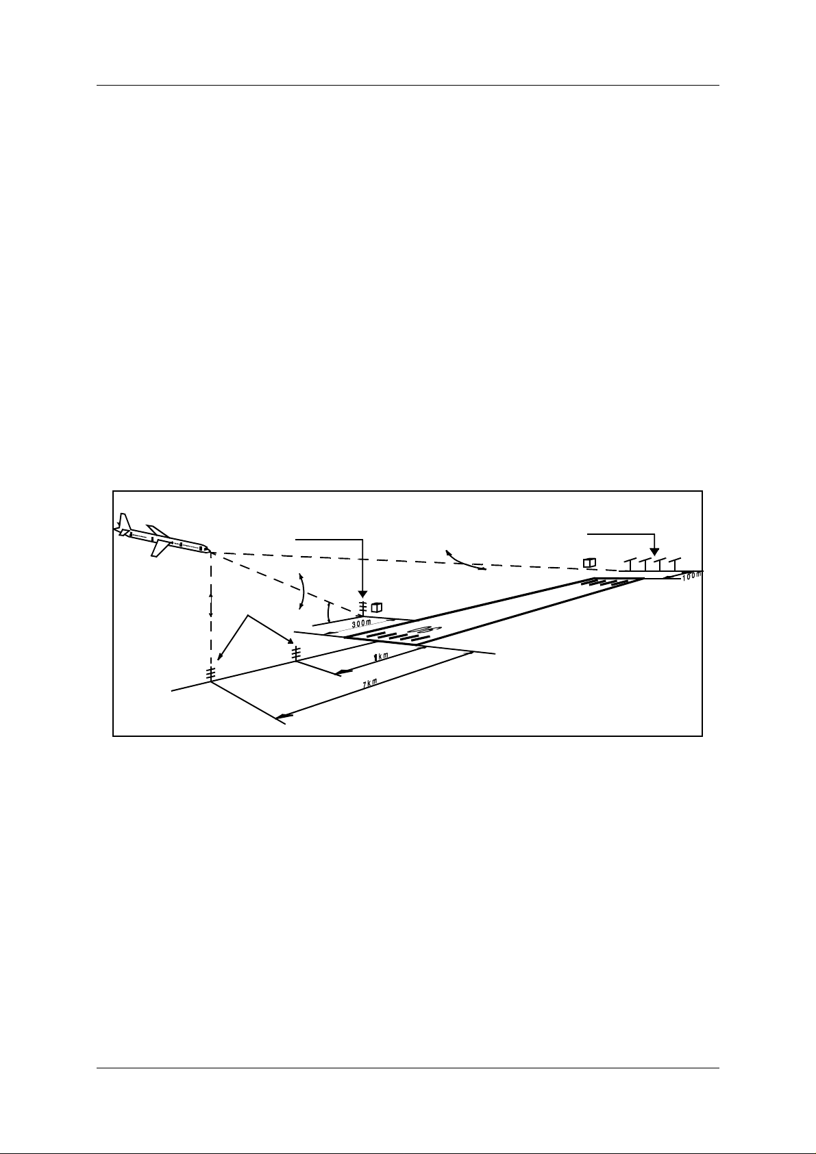
The layout of a typical ILS airport installation is shown below.
Glide Path
330 MHz
Marker Beacon
75MHz
3°
Figure 1-1Typical ILS airport installation
1.1.2 Marker Beacons Overview
The complete ILS marker beacons system comprises:
• A Marker Beacon transmitter/monitor cabinet
• A Marker Beacon antenna
• A remote control
• An Remote Maintenance Monitor (RMM) program to be installed on a PC
• Optional slave panel
• Optional backup battery
Localizer
110 MHz
HBK547-1
©1999 Navia Aviation AS 21464-5 GENERAL INFORMATION
1-1
USER MANUAL
NORMARC 7050
MARKER BEACON
REMOTE
CONTROL
UNIT
SLAVE
PANEL
RMM
SYSTEM
MARKER
BEACON
CABINET
TRANSMITTERS
AND
MODULATORS
MONITOR(S)
POWER
SUPPLY(S)
MAINS INPUT
220V/110V AC
RF OUT
RF IN
BEACON
ANTENNA
24V
BATTERY
DUAL ANTENNA SYSTEM
DISTRIBUTION
NETWORK
MONITOR
NETWORK
HBK779/1
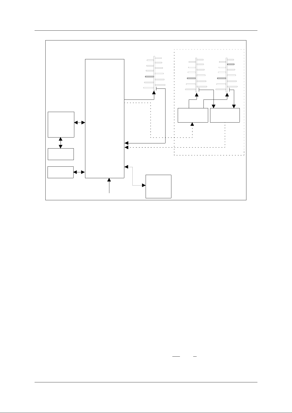
Figure 1-2 Marker beacon block diagram
1.1.3 Marker Beacons Description
The marker beacons are located verticall y beneath the localizer course line at distance 150m
(inner marker), 1km (middle marker) and 7km (outer marker) from the r unway threshold.
The beacons radiate a 75MHz radio signal with an audio Morse code. The Morse code and
modulation frequency diffe r for the outer, middle and inner marker. Outer marker transmits
dash code 400Hz, middle marker transmits dash dot code 1300Hz an d inner marke r dot code
3000Hz.
1.2 Product Type Numbers
The Normarc product numbering system is based on the following three levels:
•System
• Assembly
• Module
Systems have type numbers starting with NM, for example NM7050. Systems consist of
assemblies, modules and parts.
Assemblies have type numbers consisting of three lette rs, a three- or four- di git number and a
letter, for example CAA 1370A. CAA is an abbreviation of CA
binet Assembly, 1370 is a running number, and the last letter is the variant designator. Assemblies can consist of assemblies, modules and part s.
GENERAL INFORMATION ©1999 Navia Aviation AS
1-2
21464-5

USER MANUALNORMARC 7050
MARKER BEACON
Modules have type numbers consisting of two letters, a three- or four- digit number and a letter , for example MO 1374A. MO is an abbrevia tion of MO
nitor , 1374 is a runni ng number, and
the last letter is the variant designator. Modules consist of parts.
1.3 Abbreviations
AC : Alternating Current
ADC : Analog to Digital Converter
AGC : Automatic Gain Control
CPU : Central Processing Unit
DAC : Digital to Analog Converter
DC : Direct Current
DM : Depth of Modulation
EEPROM : Electrically Erasable Programmable Read Only Memory
EMC : Electro Magnetic Compatibility
EMI : Electro Magnetic Interference
EPROM : Erasable Programmable Read Only Memory
FIFO : First In First Out
FPGA : Field Programmable Gate Array
I/F : Inter Face
ILS : Instrument Landing System
IM : Inner Marker
LED : Light Emitting Diode
LF : Low Frequency
LRU : Line Replaceable Unit
MCU : Monitor Combiner Unit
MM : Middle Marker
NAV : NAVigation signals
NF : Near Field
OM : Out e r Ma rk e r
PC : Personal Computer
RAM : Random Access Memory
RF : Radio Frequency
RMM : Remote Maintenance Monitor
RMS : Remote Monitoring System
ROM : Read Only Memory
RTC : Real Time Clock
SC : Station Control
SRAM : Static Random Access Memory
STB : STandBy
SW : Soft Ware
TX : Transmitter
©1999 Navia Aviation AS 21464-5 GENERAL INFORMATION
1-3

USER MANUAL
NORMARC 7050
MARKER BEACON
GENERAL INFORMATION ©1999 Navia Aviation AS
1-4
21464-5
USER MANUALNORMARC 7050
MARKER BEACON
2 Physical organisation
This chapter describes the physical outline of the NM 7050
2.1 Configurations
2.1.1 Module and Assembly Location
The figures on the following pages show the locations of the modul es in the main cabinet.
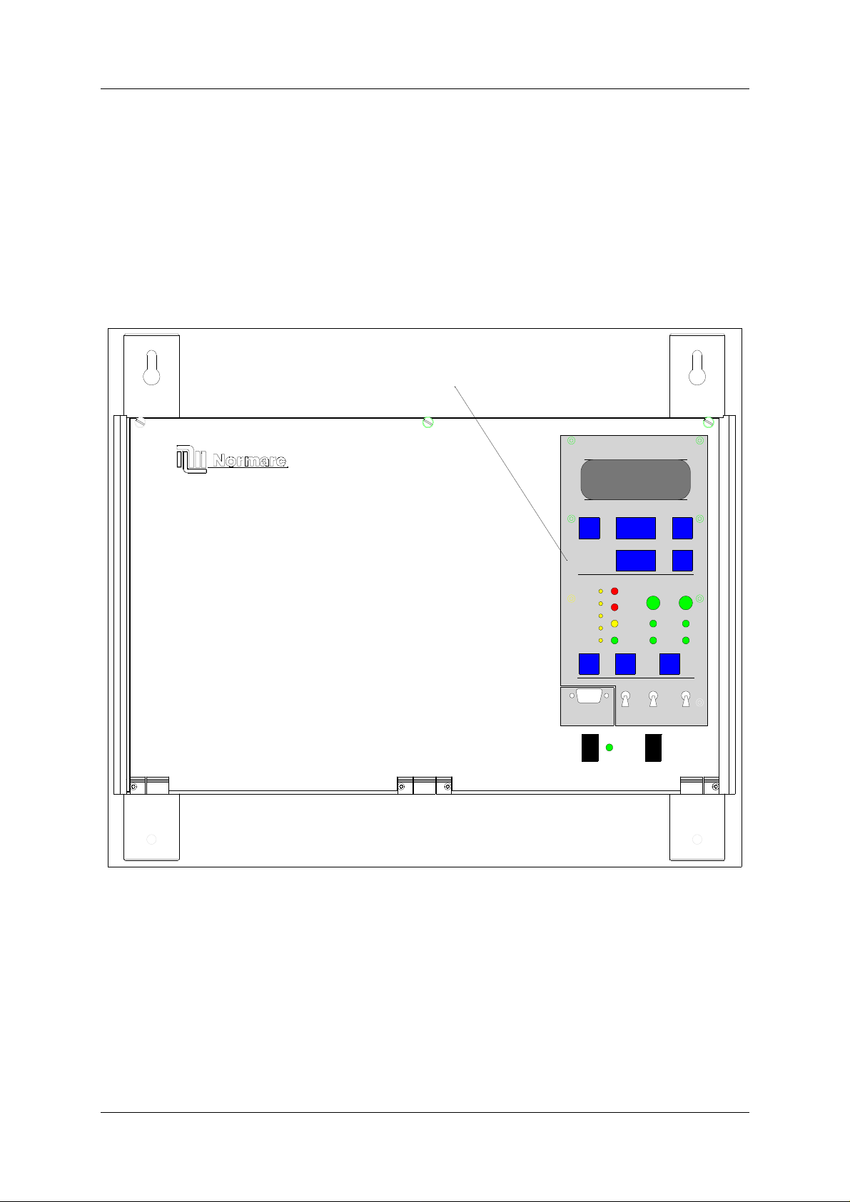
Figure 2-1 shows the front panel of the cabinet, with the control panel, on/off switch and local
PC connection.
LC1377
MARKER BEACON SYSTEM
ESC PREV NEXT
SERVICE
PARAM
DISAGR
ALARM
BATT
WARNING
MAINT
STBY
NORMAL
ON/
OFF
LOCAL
LOCAL RS232
REMOTE
ON
POWER
OFF
24V DC MAINS
CHANGE
OVER
MANUAL
ENTER
TX1
TX2
TX TO AIR
MAIN
TX1/
TX2
AUTO
WRITE
PROTECT
ON
OFF
HBK780/1
Figure 2-1 NM 7050 Front panel
Figure 2-2 shows the open cabinet in front view with indication of plug in board location.
©1999 Navia Aviation AS 21464-5 Physical organisation
2-1

USER MANUAL
NORMARC 7050
MARKER BEACON
PS 1375 TX 1373 MO 1374
POWER SUPPLY 2 *)
POWER SUPPLY 1
TRANSMITTER 2
TRANSMITTER 1
PB 1378CI 1376
MONITOR 2 **)
MONITOR 1
I
S
T
T
N
A
A
T
*) Only used in dual power systems (NM 7050 B/D)
**) Only used in dual monitor systems (NM 7050 C/D)
HBK781/1
Antistatic sock et
Figure 2-2 NM 7050 Module Location
Notice the location of the dif ferent pl ug in boards. It is essent ial for th e MB to function, that the
cards are placed in these locations. If your MB is configured with only one plugin board of
each type, they must be placed in the number one locations. The backplane is however ,
marked with notifications of where each boards place is..
Τ The electronic devices inside NM 7050 are sensitive to Electro Static Discharge
(ESD). Please follow the instructions given in the preface of this manual to avoid
damage during servicing and transportation.
Physical organisation ©1999 Navia Aviation AS
21464-5
2-2

USER MANUALNORMARC 7050
MARKER BEACON
3 System Description
3.1 Introduction / Overview
The system is housed in a compact cabinet. There are four models/configurations of the NM
7050.
Variant Monitor Power Supply
NM7050A 1 1
NM7050B 1 2
NM7050C 2 1
NM7050D 2 2
Table3-1 Models / Configurations
As shown in Table 3-1, the beacon can have one or two monitor units and one or two power
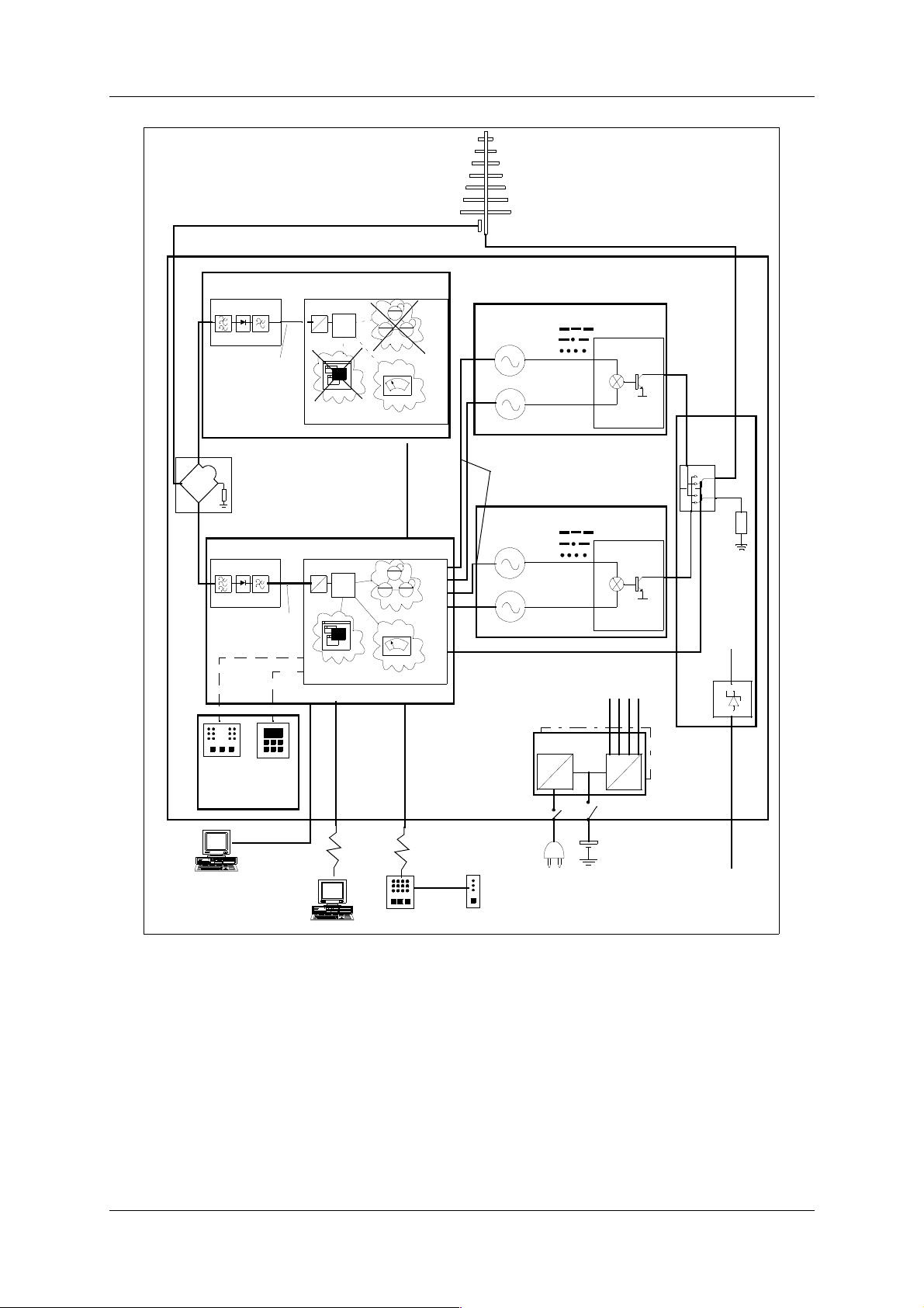
supply units. Figure 3-1 shows a blo ck diagram of the MB system.
The monitor and transmitter control functi on is based on sof tware. The system is based on
modern technology with ext ensive Remote Moni toring and Maintenance cap abil ities, and very
high reliability and integrity.
©1999 Navia Aviation AS 21464-5 System Description
3-1
USER MANUAL
NORMARC 7050
MARKER BEACON
MONITOR RF
FRONTEND
MO 1374
SPLITTER ONLY PRESENT
IF TWO MONITORS
MONITOR RF
FRONTEND
MO 1374
LOCAL
CONTROL
LC 1377
BASEBAND+
RF LEVEL
BASEBAND+
RF LEVEL
KEYBOARD
DISPLAY
OPTIONAL MONITOR 2
MONITOR
A
CPU
D
MAINTENANCE +
RMM INTERFACE
MONITOR
CPU
A
D
MAINTENANCE +
RMM INTERFACE
MONITORING
MONITOR 2
MONITOR 1
MONITORING
DATA
STATION
CONTROL
STATION
CONTROL
NM7050 - MARKER BEACON
TRANSMITTER 1
TX 1373
LF
GENERATOR
RF
OSCILLATOR
ON/
OFF
MODULATION DEPTH
OUTPUT RF LEVEL
KEYING NORMAL/OFF/CONT.
STATUS
400 Hz
1.300 Hz
3.000 Hz
75 MHz
TX 1373
LF
GENERATOR
RF
OSCILLATOR
ON/
OFF
400 Hz
1.300 Hz
3.000 Hz
75 MHz
OPTIONAL POWER
PS 1375
POWER
AC
SUPPLY
DC
POWER
AMPLIFIER
TRANSMITTER 2
POWER
AMPLIFIER
TX1/TX2
+20V
+/-15V
+5V
DC
DC
CHANGE
OVER
DUMMY
LOAD
CI 1376
CONNECTION
INTERFACE
RMM
LOCAL PC
HBK782/1
RMM
REMOTE PC
LINE+
MODEM
REMOTE
CONTROL
LINE+
MODEM
SLAVE
PANEL
MAINS BATTERY
SENSORS ETC.
Figure 3-1 MB block diagram
3.2 Transmitters / Modulators
The NM7050 consists of two TX1373A transmitters. The main transmitter is connected to the
antenna, while the standby transmit ter is connected to dummy load. A failure in the main
transmitter will cause an automatic change over to the standby transmitter.
The audio signals are generated in the LF circuitry ma inly by a Field Programmable Gate
Array (FPGA). A strap field selects Inner, Middle or Outer Marker settings.
An onboard oscillator generates a 75MHz carri er wave whi ch is amplit ude modul ated wit h the
System Description ©1999 Navia Aviation AS
3-2
21464-5

USER MANUALNORMARC 7050
MARKER BEACON
audio signal in the Power Amplifier (PA). The PA is capable of delivering up to 4W power at
97% depth of modulation.
Unwanted frequencies are removed by a lowpass filt er after the PA.
3.3 Monitors / Transmitter Control
The marker beacon has one or two MO1374 monitor modules depending on model (Table 3-
1).
The MO1374 is mainly a microprocessor based module. It contains the MB software and
forms the basis of the monitor, station control, system maintenance handling and RMS user
interface.
A detection of error in the transmitter signal causes change-over to the standby transmitter.
Failure of the standby transmitter leads to an alarm and optional shutdown of the standby
transmitter.
On a system with two monitor units, both must report error for alarm to be generated (2 of 2
voting). If the monitors disagree, the WARNING and DISAGR LEDs on the front panel is lit.
The MO1374 consists of two submodules:
The RF frontend
receives a RF signal from the antenna (or recombining network for dual
antenna system). It demodulates the signal into analogue values propotional to the RF
power, the modulation depth and the morse code envelope. These parameters are digitized
and monitored by the CPU section.
The CPU section
includes an 80CI88 CPU, memory, communication ports and an AD con-
verter system.
3.4 Power Systems
The marker beacon can have either one or two PS1375 power modules depending on model
(Table 3-1). The PS1375 is 100W with 120V or 230V AC input voltage and +28V/3.5 A, +20/
2.5A, ±12V/1.25A and 5V/6A DC output voltages. Outputs are short circuit protected. On the
NM7050 B/D the two modules operate in parallel.
The 28V output is temperature compensated to ensure optimum battery charging. It gives
26.4V at 50°C and linearly increase to 29.6V at -30°C.
The backup battery is an external 24V battery. The battery gives a backup time of 6 hours,
and have external charging possibiliti es for longer backup time. This battery is automatically
brought into circuit on mains power fail ure. The charging time is approximately eight hours
with one PS1375 and five hours with two PS1375.
3.5 Remote control system
The remote control unit is used in the tower or in the technical control room. It has indicators
for operating status as well as det ailed warnings and an aural alarm device with reset. It can
control equipment on/off and change over, and has an Access Grant switch to allow/inhibit
remote control from the RMM system.
©1999 Navia Aviation AS 21464-5 System Description
3-3
 Loading...