


HCS300
KEELOQ® Code Hopping Encoder
FEATURES
Security
• Programmable 28-bit serial number
• Programmable 64-bit encryption key
• Each transmission is unique
• 66-bit transmission code length
• 32-bit hopping code
• 34-bit fixed code (28-bit serial number,
4-bit button code, 2-bit status)
• Encryption keys are read protected
Operating
• 2.0—6.3V operation
• Four button inputs
• No additional circuitry required
• 15 functions available
• Selectable baud rate
• Automatic code word completion
• Battery low signal transmitted to receiver
• Non-volatile synchronization data
Other
• Easy to use programming interface
• On-chip EEPROM
• On-chip oscillator and timing components
• Button inputs have internal pulldown resistors
• Current limiting on LED
• Minimum component count
• Synchronous transmission mode
Typical Applications
The HCS300 is ideal for Remote Keyless Entry (RKE)
applications. These applications include:
• Automotive RKE systems
• Automotive alarm systems
• Automotive immobilizers
• Gate and garage door openers
• Identity tokens
• Burglar alarm systems
output
DESCRIPTION
The HCS300 from Microchip T echnology Inc., is a code
hopping encoder designed for secure Remote Keyless
Entry (RKE) systems. The HCS300 utilizes the
®
code
hopping technology, which incorporates high security, a
small package outline and low cost to make this device
a perfect solution for unidirectional remote keyless
entry systems and access control systems.
PACKAGE TYPES
PDIP, SOIC
8
S0
S1
S2
S3
1
HCS300
2
3
4
VDD
LED
7
6
PWM
V
SS
5
HCS300 BLOCK DIAGRAM
LED
PWM
Oscillator
Reset circuit
VSS
VDD
LED
driver
EEPROM
Controller
32-bit shift register
Button input port
S
S
2
3
S1S
Encoder
0
Power
latching
and
switching
KEELOQ is a registered trademark of Microchip Technology, Inc.
Microchip’s Secure Data Products are covered by some or all of the following patents:
Code hopping encoder patents issued in Europe, U.S.A., and R.S.A. — U.S.A.: 5,517,187; Europe: 0459781; R.S.A.: ZA93/4726
1999 Microchip Technology Inc. Preliminary DS21137E-page 1

HCS300
The HCS300 combines a 32-bit hopping code
generated by a non-linear encr y ption algorithm, with a
28-bit serial number and six status bits to create a 66bit transmission stream. The length of the transmission
eliminates the threat of c ode scanning and the code
hopping mechanism makes each transmission unique,
thus rendering code capture and resend (code grabbing) schemes useless.
The encryption key, serial number, and configuration
data are stored in EEPROM, which is not accessible via
any external connection. This makes the HCS3 00 a
very secure unit. The HCS300 provides an easy to use
serial interface for programming the necessary security
keys, system parameters, and configuration data.
The encyrption keys and code combinations are programmable but read-protected. The keys can only be
verified after an automatic erase and programming
operation. This protects against attempts to gain
access to keys and manipulate synchronization values.
The HCS300 operates over a wide voltage range of
2.0V to 6.3V and has four button inputs in an 8-pin
configuration. This allows the system designer the
freedom to utilize up to 15 functions. The only
components required for device operation are the buttons and RF circuitry, allowing for a very low
system cost.
1.0 SYSTEM OVERVIEW
Key Terms
• Manufacturer’s code - a 64-bit word, unique to
each manufacturer, used to produce a unique
encryption key in each transmitter (encoder).
• Encryption Key
and programmed into the encoder during the
manufacturing process. The encryption key
controls the encryption algorithm and is stored in
EEPROM on the encoder device.
1.1 Learn
The HCS product family facilitates several learn strategies to be implemented on the decoder. The following
are examples of what can be done. It must be pointed
out that there exists some third-party pat ents on learning strategies and implementation.
1.1.1 NORMAL LEARN
The receiver uses the same information that is transmitted during nor mal operation to der ive the transmitter’s secret key, decrypt t he discrimination value and
the synchronization counter.
- a unique 64-bit key generated
1.1.2 SECURE LEARN* The transmitter is activated through a special button
combination to transmit a stored 48-bit value (random
seed) that can be used for key generation or be part of
the key. Transmission of the random seed can be disabled after learning is completed.
The HCS300 is a code hopping encoder device that is
designed specifically for keyless entry systems,
primarily for vehicles and hom e garage door opener s.
It is meant to be a cost-effective, yet secure solution to
such systems. The encoder por tion of a keyless entry
system is meant to be held by the user and operated to
gain access to a vehicle or restricted area. The
HCS300 requires very few external components
(Figure 2-1).
Most keyless entry systems transmit the s ame code
from a transmitter every time a button is pushed. The
relative number of code combinations for a low end
system is also a relatively small number. These
shortcomings provide the means for a sophisticated
thief to create a device that ‘grabs’ a transmission and
re-transmits it later or a device that scans all possible
combinations until the correct one is found.
The HCS300 employs the code hopping technology
and an encryption algor ithm to ach ieve a high level of
security. Code hopping is a method by which the code
transmitted from the transmitter to the receiver is
different every time a button is pushed. This method,
coupled with a transmission length of 66 bits, virtually
eliminates the use of code ‘grabbing’ or code
‘scanning’.
As indicated in the block diagram on page one, the
HCS300 has a small EEPROM array which must be
loaded with several parameters before use. The most
important of these values are:
• A 28-bit serial number which is meant to be
unique for every encoder.
• An encryption key that is generated at the time of
production.
• A 16-bit synchronization value.
The serial number for each transmitter is programmed
by the manufacturer at the time of production. The
generation of the encryption key is done using a key
generation algorithm (Figure 1-1). Typically, inputs to
the key generation algorithm are the serial number of
the transmitter and a 64-bit manufacturer’s code. The
manufacturer’s code is chosen by the system
manufacturer and must be carefully controlled. The
manufacturer’s code is a pivotal part of the overall
system security.
DS21137E-page 2 Preliminary 1999 Microchip Technology Inc.
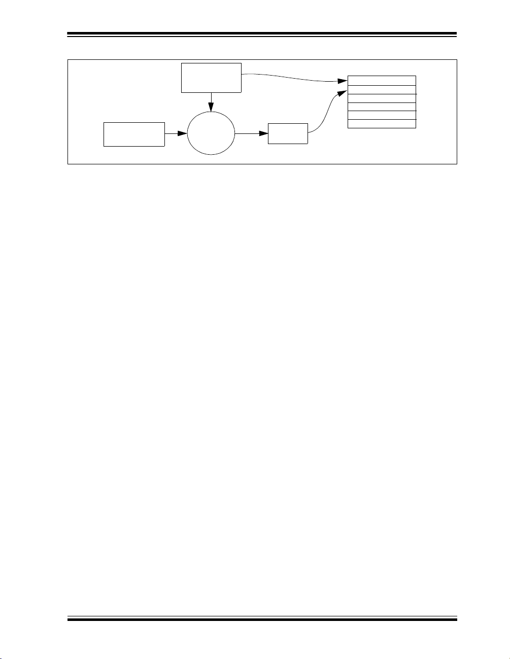
FIGURE 1-1: CREATION AND STORAGE OF ENCRYPTION KEY DURING PRODUCTION
HCS300 EEPROM Array
Serial Number
Encryption Key
Sync Counter
Manufacturer’s
Code
Transmitter
Serial Number or
Seed
Key
Generation
Algorithm
Encryption
Key
HCS300
.
.
.
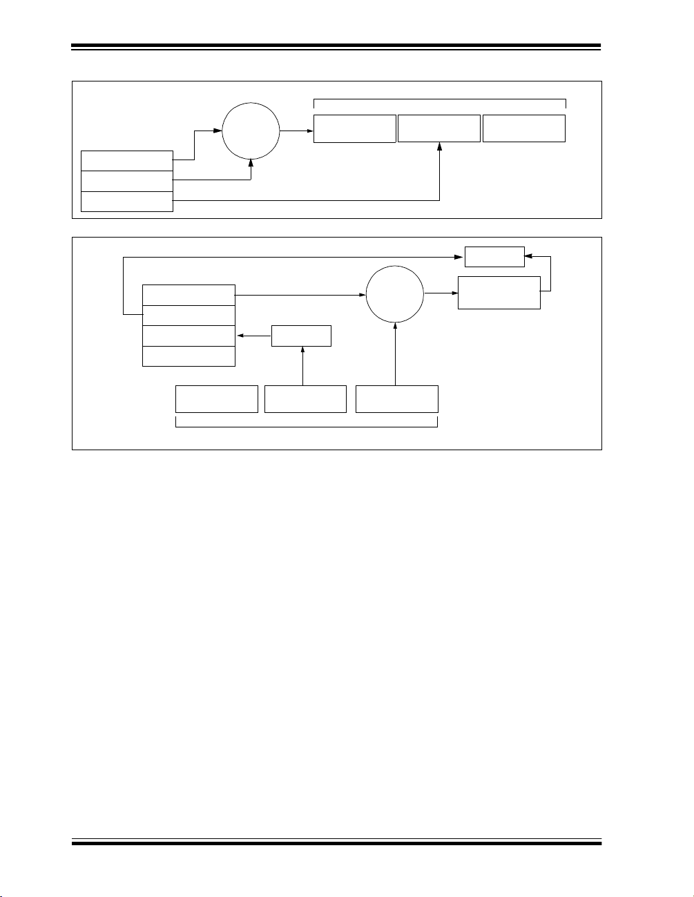
The 16-bit synchronization value is the basis for the
transmitted code changing for each t ransmission, and
is updated each time a button is pressed. Because of
the complexity of the code hopping encr yption algorithm, a change in one bit of the sync hronization value
will result in a large change in the actual transmitted
code. There is a relationship (Fig ure 1-2) between the
key values in EEPROM and how they are used in the
encoder. Once the encoder detects that a button has
been pressed, the encoder reads the button and
updates the synchronization counter. The synchronization value is then combined with the encry ption key in
the encryption algorithm an d the output is 32 bits of
encrypted information. This data will change with every
button press, hence, it is referred to as the hoppi ng
portion of the code word. The 32-bit hopping code is
combined with the button information and the serial
number to form the code word transmitted to the
receiver. The code word format is explained in detail
in Section 4.2.
Any type of controller may be used as a receiver, but it
is typically a microcontroller w ith compatible firmware
that allows the receiver to operate in conjunction with a
transmitter, based on the HCS300. Section 7.0
provides more detail on integrating the HCS300 into a
total system.
Before a transmitter can be used with a particular
receiver, the transmitter must be ‘learned’ by the
receiver. Upon learning a transmitter, information is
stored by the receiver so that it may track the
transmitter, including the serial number of the
transmitter, the current synchronization value for that
transmitter and the same encryption key that is used on
the transmitter. If a receiver receives a message of valid
format, the serial number is checked and, if it is from a
learned transmitter, the message is decr ypted a nd the
decrypted synchronization coun ter is checked against
what is stored. If the sy nchronization value is verified,
then the button status is checked to see what operation
is needed. Figure 1-3 shows the relationship between
some of the values stored by the receiver and the values received from the transmitter.
1999 Microchip Technology Inc. Preliminary DS21137E-page 3
HCS300
FIGURE 1-2: BASIC OPERATION OF TRANSMITTER (ENCODER)
Transmitted Information
KEELOQ
Encryption
EEPROM Array
Encryption Key
Sync Counter
Serial Number
FIGURE 1-3: BASIC OPERATION OF RECEIVER (DECODER)
EEPROM Array
Encryption Key
Sync Counter
Serial Number
Manufacturer Code
Button Press
Information
Algorithm
Check for
Match
Serial Number
Received Information
32 Bits of
Encrypted Data
Serial Number
KEELOQ
Decryption
Algorithm
32 Bits of
Encrypted Data
Button Press
Information
Check for
Match
Decrypted
Synchronization
Counter
DS21137E-page 4 Preliminary 1999 Microchip Technology Inc.
HCS300
2.0 DEVICE OPERATIO N
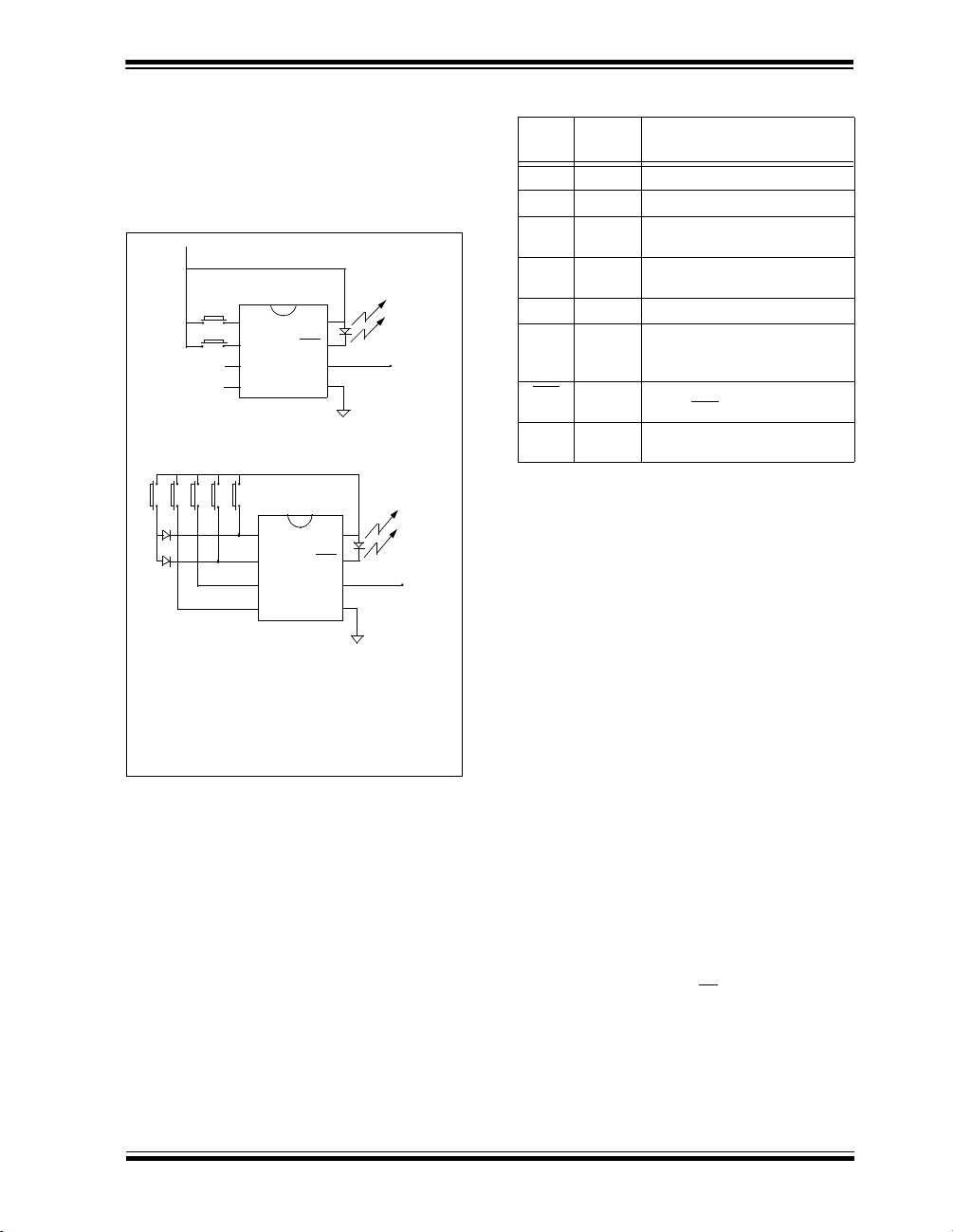
As shown in the typical application circuits (Figure 2-1),
the HCS300 is a simple device to use. It requires only
the addition of buttons and RF circuitry for use as the
transmitter in your security application. A description of
each pin is described in Table 2-1.
FIGURE 2-1: TYPICAL CIRCUITS
VDD
B0
B1
B4 B3 B2 B1 B0
Note: Up to 1 5 fu nc tio ns c a n be imp l em e nte d by pre s s-
S0
VDD
S1
S2
S3
2 button remote control
5 button remote control (Note)
ing more than one button simultaneously or by
using a suitable diode array.
LED
PWM
SS
V
S0
VDD
LED
S1
PWM
S2
S3
SS
V
Tx out
VDD
Tx out
TABLE 2-1: PIN DESCR IPTIONS
Name
S0 1
S1 2
S2 3
Pin
Number
Description
Switch input 0
Switch input 1
Switch input 2/Can also be clock
pin when in programming mode
S3 4
Switch input 3/Clock pin when in
programming mode
V
SS 5
PWM 6
Ground reference connection
Pulse width modulation (PWM)
output pin/Data pin for
programming mode
LED
VDD
Cathode connection for directly
7
driving LED
Positive supply voltage
8
during transmission
connection
The high security level of the HCS300 is bas ed on the
patented
technology. A block cipher type of encryption
algorithm based on a block length of 32 bits and a key
length of 64 bits is used. The algorithm obscures the
information in such a way that even if the transmission
information (before coding) differs by only one bit from
the information in the previous transmission, the next
coded transmission will be totally different. Statistically,
if only one bit in the 32-bit string of information
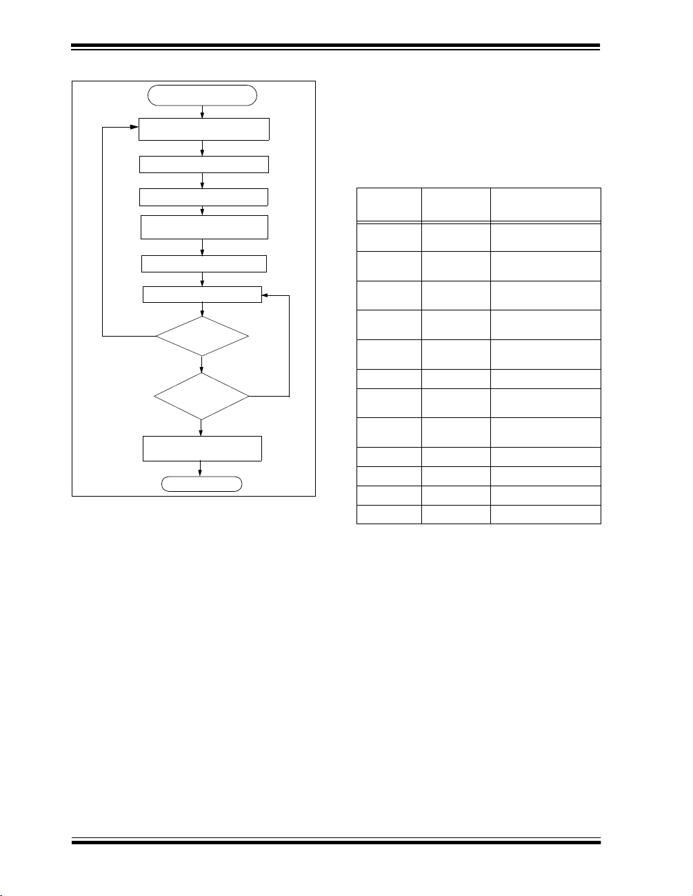
changes, approximately 50 percent of the coded transmission will change. The HC S300 will wake up upon
detecting a switch closure and then delay approximately 10 ms for switch debounce (Figure 2-2). The
synchronized information, fixed information, and switch
information will be encrypted to form the hopping code.
The encrypted or hopping code portion of the transmission will change every time a button is pressed, even if
the same button is pushed again. Keeping a button
pressed for a long time will result in the same code
word being transmitted, until the button is released or
timeout occurs. A code that has been transmitted w ill
not occur again for more than 64K transmissions. This
will provide more than 18 years of typical use before a
code is repeated, based on 10 operations per day.
Overflow information programmed into the encoder can
be used by the decoder to extend the number of unique
transmissions to more than 192K.
If in the transmit process it is detected that a new button(s) has been pressed, a reset will immediately be
forced and the code word will not
be completed. Please
note that buttons removed will not have any effect on
the code word unless no buttons remain pressed in
which case the current code word will be completed
and the power down will occur.
1999 Microchip Technology Inc. Preliminary DS21137E-page 5
HCS300
FIGURE 2-2: ENCODER OPERATION
Power Up
(A button has been pressed)
Reset and Debounce Delay
(10 ms)
Sample Inputs
Update Sync Info
Encrypt With
Encryption Key
Load Transmit Register
Transmit
Yes
Buttons
Added
?
No
All
Buttons
Released
?
Yes
Complete Code
Word Transmission
Stop
No
3.0 EEPROM MEMORY ORGANIZATION
The HCS300 contains 192 bits (12 x 16-bit words) of
EEPROM memory (Table 3-1). This EEPROM array is
used to store the encryption key information,
synchronization value, etc. Fur ther descripti ons of the
memory array is given in the following sections.
TABLE 3-1: EEPROM MEMORY MAP
WORD
ADDRESS
0
1
2
3
4
5
6
7
8
9
10
11
Note: The MSB of the serial number contains a bit
3.1 Key_0 - Key_3 (64-Bit Encryption Key)
The 64-bit encryption key is used by the transmitter to
create the encrypted message transmitted to the
receiver. This key is created and programmed at the
time of production using a key generation algorithm.
Inputs to the key generation algorithm are the serial
number for the partic ular transmitter b eing us ed and a
secret manufacturer’s code. While the key generation
algorithm supplied is the typical method used, a user
may elect to create their own method of key generation.
This may be done, providing that the decoder is programmed with the same means of creating the key for
decryption purposes. If a seed is used, the seed will
also form part of the input to the key generation algorithm.
MNEMONIC DESCRIPTION
KEY_0 64-bit encryption key
(word 0)
KEY_1 64-bit encryption key
(word 1)
KEY_2 64-bit encryption key
(word 2)
KEY_3 64-bit encryption key
(word 3)
SYNC 16-bit synchronization
value
RESERVED Set to 0000H
SER_0 Device Serial Number
(word 0)
SER_1(Note) Device Serial Number
(word 1)
SEED_0 Seed Value (word 0)
SEED_1 Seed Value (word 1)
EN_KEY 16-bit Envelope Key
CONFIG Config Word
used to select the auto shutoff timer.
DS21137E-page 6 Preliminary 1999 Microchip Technology Inc.

HCS300
3.2 SYNC (Synchronization Counter)
This is the 16-bit synchronization value that is used to
create the hopping code for transmission. This value
will be changed after every transmission.
3.3 SER_0, SER_1 (Encoder Serial Number)
SER_0 and SER_1 are the lower and upper words of
the device serial number, respectively. Although there
are 32 bits allocated for the seri al number, only the
lower order 28 bits are transmitted. The ser ial number
is meant to be unique for every transmitter. The most
significant bit of the serial number (Bit 31) is used to
turn the auto shutoff timer on or off.
3.3.1 AUTO SHUTOFF TIMER SELECT
The most significant bit of the ser ial number (Bit 31) is
used to turn the Auto shutoff timer on or off. This timer
prevents the transmitter from draining the battery
should a button get stuck in the on position for a long
period of time. The time period is approximately
25 secon ds, after which the device will go to the Timeout mode. When in the Time-out mode, the device will
stop transmitting, although since some circuits within
the device are still active, the current draw within the
Shutoff mode will be more than Standby mode. If the
most significant bit in the serial number is a on e, then
the auto shutoff timer is enabled, and a zero in the most
significant bit will disable the timer. The length of the
timer is not selectable.
3.4 SEED_0, SEED_1 (Seed Word)
This is the two word (32 bits) seed code that will be
transmitted when all four buttons are pressed at the
same time. This allows the system designer to implement the secure learn feature or use this fixed code
word as part of a different key generation/tracking process or purely as a fixed code transmission.
3.5 EN_Key (Envelope Encryption Key)
Envelope encryption is a selectable option that
encrypts the por tion of the transmission that contai ns
the transmitter serial number. Selecting this option is
done by setting the appropriate bit in the configuration
word (Table 3-2). Normally, the serial number is
transmitted in the clear (un-encrypted), but for an
added level of security, the system designer may elect
to implement this option. The envelope encryption key
is used to encrypt the serial number por tion of the
transmission, if the envelope encryption option has
been selected. The envelope encryption algorithm is a
different algorithm than the key generation or transmit
encryption algorithm. The EN_key is typically a random
number and the same for all transmitters in a system.
3.6 Configuration Word
The configuration word is a 16-bit word stored in
EEPROM array that is used by the device to store
information used during the encryption process, as well
as the status of option configurations. Further
explanations of each of the bits are described in the
following sections.
TABLE 3-2: CONFIGURATION WORD
Bit Number Bit Description
Discrimination Bit 0
0
Discrimination Bit 1
1
Discrimination Bit 2
2
Discrimination Bit 3
3
Discrimination Bit 4
4
Discrimination Bit 5
5
Discrimination Bit 6
6
Discrimination Bit 7
7
Discrimination Bit 8
8
Discrimination Bit 9
9
10
11
12
13
14
15
3.6.1 DISCRIMINATION VALUE
The discrimination value can be programmed with a ny
value to serve as a post decryption check on the
decoder end. In a typical system, this will be
programmed with the 10 least significant bits of the
serial number, which will also be stored by the receiver
system after a transmitter has been learned. The
discrimination bits are part of the inform atio n th at is to
form the encrypted por tion of the transmission. After
the receiver has decrypted a transmission, the
discrimination bits can b e checked against the stored
value to verify that the decryption process was valid.
3.6.2 OVERFLOW BITS (OVR0 AND OVR1) The overflow bits are used to extend the number of pos-
sible synchronization values. The synchronization
counter is 16 bits in length, yielding 65,536 values
before the cycle repeats. Under typical use of
10 operations a day, this will provide nearly 18 years of
use before a repeated value will be used. Should the
system designer conclude that is not adequate, then
the overflow bits can be utilized to extend the number
of unique values. This can be done by programming
OVR0 and OVR1 to 1s at the time of production. The
encoder will automatically clear OVR0 the first time that
the synchronization value wraps from 0xFFFF to
Overflow Bit 0 (OVR0)
Overflow Bit 1 (OVR1)
Low Voltage Trip Point Select
Baudrate Select Bit 0 (BSL0)
Baudrate Select Bit 1 (BSL1)
Envelope Encryption Select (EENC)
(DISC0 TO DISC9)
1999 Microchip Technology Inc. Preliminary DS21137E-page 7
HCS300
0x0000 and clear OVR1 the second time the counter
wraps. Once cleared, OVR0 and OVR1 cannot be set
again, thereby creating a permanent record of the
counter overflow. This prevents fast cycling of 64K
counter. If the decoder system is programmed to track
the overflow bits, then the effective number of unique
synchronization values can be extended to 196,608. If
programmed to zero, the system will be compatible with
the NTQ104/5/6 devices (i.e., no overflow with discrimination bits set to zero).
3.6.3 ENVELOPE ENCRYPTION (EENC) If the EENC bit is set to a 1, the 32-bit fixed code par t
of the transmission will also be encrypted so that it will
appear to be random. The 16-bit envelope key and
envelope algorithm will be used for encryption.
3.6.4 BAUDRATE SELECT BITS (BSL0, BSL1) BSL0 and BSL1 select the speed of transmission and
the code word blanking. Table 3-3 shows how the bits
are used to select the different baud rates and
Section 5.2 provides detailed explanation in code word
blanking.
TABLE 3-3: BAUDRATE SELECT
BSL1 BSL0
Basic Pulse
Element
Code Words
Transmitted
0 0 400µs All
0 1 200µs 1 out of 2
1 0 100µs 1 out of 2
1 1 100µs 1 out of 4
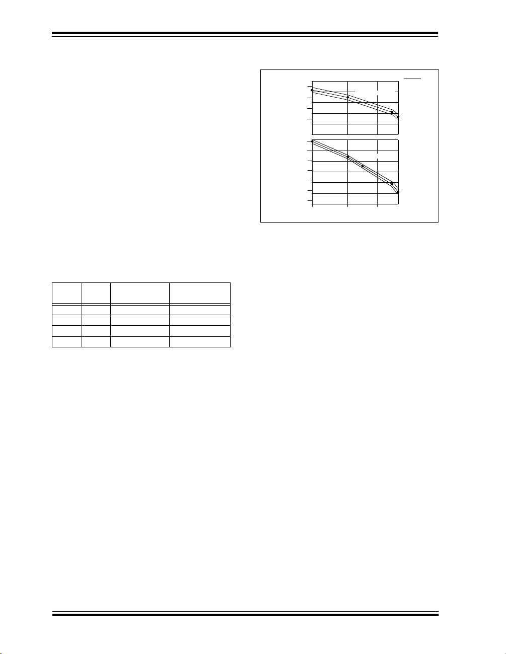
3.6.5 LOW VOLTAGE TRIP POINT SELECT The low voltage trip point select bit is used to tell the
HCS300 what
VDD level is being used. This information
will be used by the device to de termi ne when to s end
the voltage low signal to the receiver. When this bit is
set to a one, the
from a 5 volt or 6 volt
the
VDD level is assumed to be 3.0 volts. Refer to
VDD level is assumed to be operating
VDD level. If the bit is set l ow, then
Figure 3-1 for voltage trip point.VLOW is tested at 6.3V
at -25°C and +85°C and 2.0V at -25°C and +85°C
FIGURE 3-1: TYPICAL VOLTAGE TRIP
POINTS
Volts (V)
4.2
2.6
2.2
2.0
1.8
1.6
1.4
4.0
3.8
3.6
2.4
-40
VLOW sel = 1
VLOW sel = 0
05085
VLOW
Temp (C)
4.0 TRANSMITTED WORD
4.1 Transmission Format (PWM)
The HCS300 transmission is made up of several parts
(Figure 4-1). Each transmission is begun with a
preamble and a header, followed by the encrypted and
then the fixed data. The actual data is 66 bits which
consists of 32 bits of encrypted data and 34 bits of fixed
data. Each transmission is followed by a guard period
before another transmission can begin. Refer to
Table 8-4 for transmission timing requirements. The
encrypted por tion provides up to four billion chang ing
code combinations and includes the button status bits
(based on which buttons were activated) along with the
synchronization counter value and some discrimination
bits. The fixed portion is compri sed of the status bits,
the function bits and the 28-bit serial number. The fixed
and encrypted sections combined increase the number
of combinations to 7.38 x 10
4.2 Synchronous Transmission Mode
Synchronous transmission mode can be u sed to clock
the code word out using an external clock.
To enter synchronous transmission mode, the programming mode start-up sequen ce must be executed
as shown in Figure 4-3. If either S1 or S0 is set on the
falling edge of S2 (or S3), the device enters synchronous transmission mode. In this mode, it functions as a
normal transmitter, with the exception that the timing of
the PWM data string is contr olled externally and 16
extra bits are transmitted at the end with the code word.
The button code will be the S0, S1 value at the falling
edge of S2 or S3. The timing of the PWM data string is
controlled by supplying a clock on S2 or S3 and should
not exceed 20 kHz. The code word is the same as in
PWM mode with 16 reser ved bits at the end of the
word. The reserved bits can be ignore d. When in syn-
19
.
DS21137E-page 8 Preliminary 1999 Microchip Technology Inc.
 Loading...