

Leica Geosystems TPS700 Series, TPS700auto User Manual
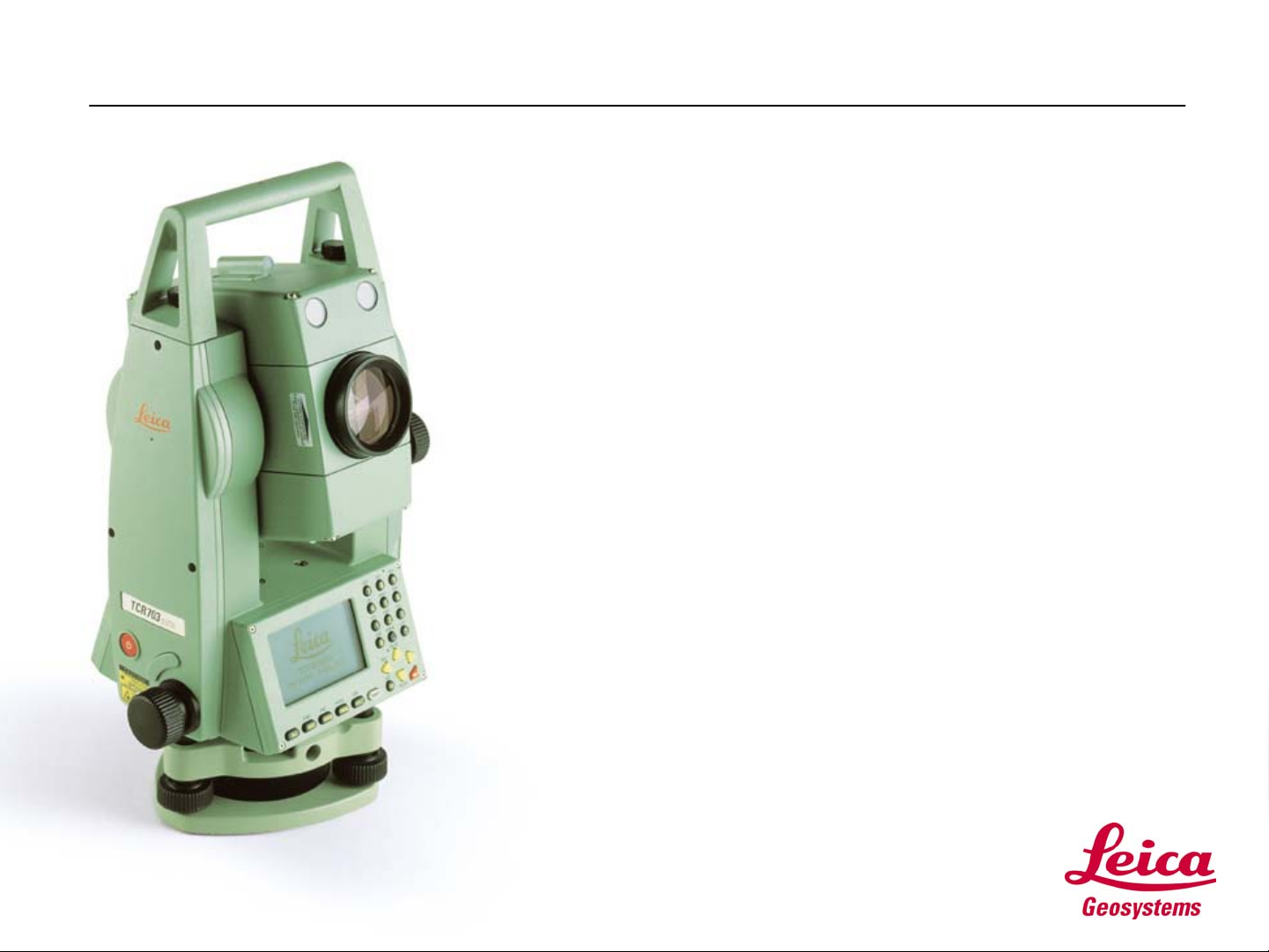
TPS700 Performance Series: TPS700auto
Steps
To
Productivity
Page 1
A Leica Advantage Self Study Guide
Introduction
• Welcome to “TPS700auto: Three Steps to
Productivity”.
• Three Steps to Productivity is a Leica Advantage
Self Study Guide and is designed to familiarize
you with the key components of your new
TPS700auto Total Station.
• Three Steps to Productivity will not teach you how
to use every feature on board your TPS700auto,
but will get you acquainted with three key functions
on board your instrument which are common to
most of the surveying tasks you are likely to
encounter.
• Once you’ve taken these first three steps, you will
be familiar enough with the operating concepts of
the TPS700auto to step out on your own to use all
of the versatile features of the instrument.
Page 2
Before You Start
• Before you start, please read the
following pages from the “TPS700
Performance Series User Manual”
(Version 2.0):
• Introduction, pages 6-11
• Measuring Preparation / Setting Up,
pages 15 – 20, 23-24,
• This study guide will refer to exercises
found in the accompanying document
file, TPS700auto_Exercises.doc.
• Print the file for your self study
workbook, “TPS700auto Self Study
Exercises”.
• The best way to learn to use your new
instrument is to take the time now to
punch the buttons and to work through
the exercises. Good luck and have fun!
Page 3
Contents
• Step 1: Configuring
• Step 2: Surveying
Page 4
• Step 3: Setting Out
Step 1: Configuring
• Configuring
• There are many ways to configure your
TPS700auto Total Station.
• This Self Study will step you through one way
to do it. It’s not the only way, or necessarily
the best, but will serve as a basis for learning.
• Set your instrument up next to your PC.
• Configure your instrument by following the
directions on the following screens.
Page 5
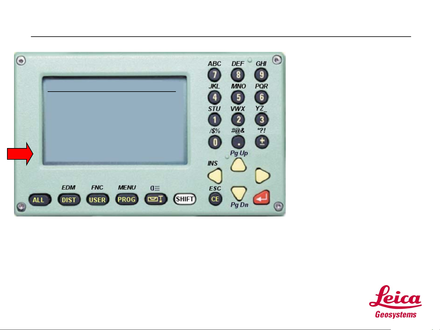
Step 1: Configuring
• Configuring your
TPS700auto:
----------MEAS & REC-----------1/4
Pt Id
TgHt
Hz
V
:
:
:
:
68º44’32”
94 º45”46”
:
100
0.000 m
----.--- m
<SETUP> <Hz0> <QCODE>
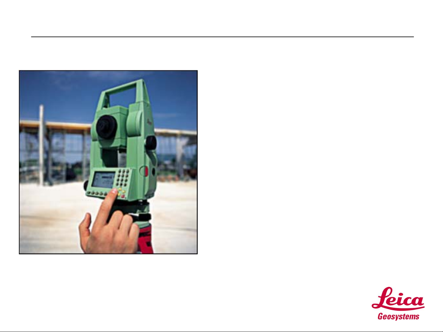
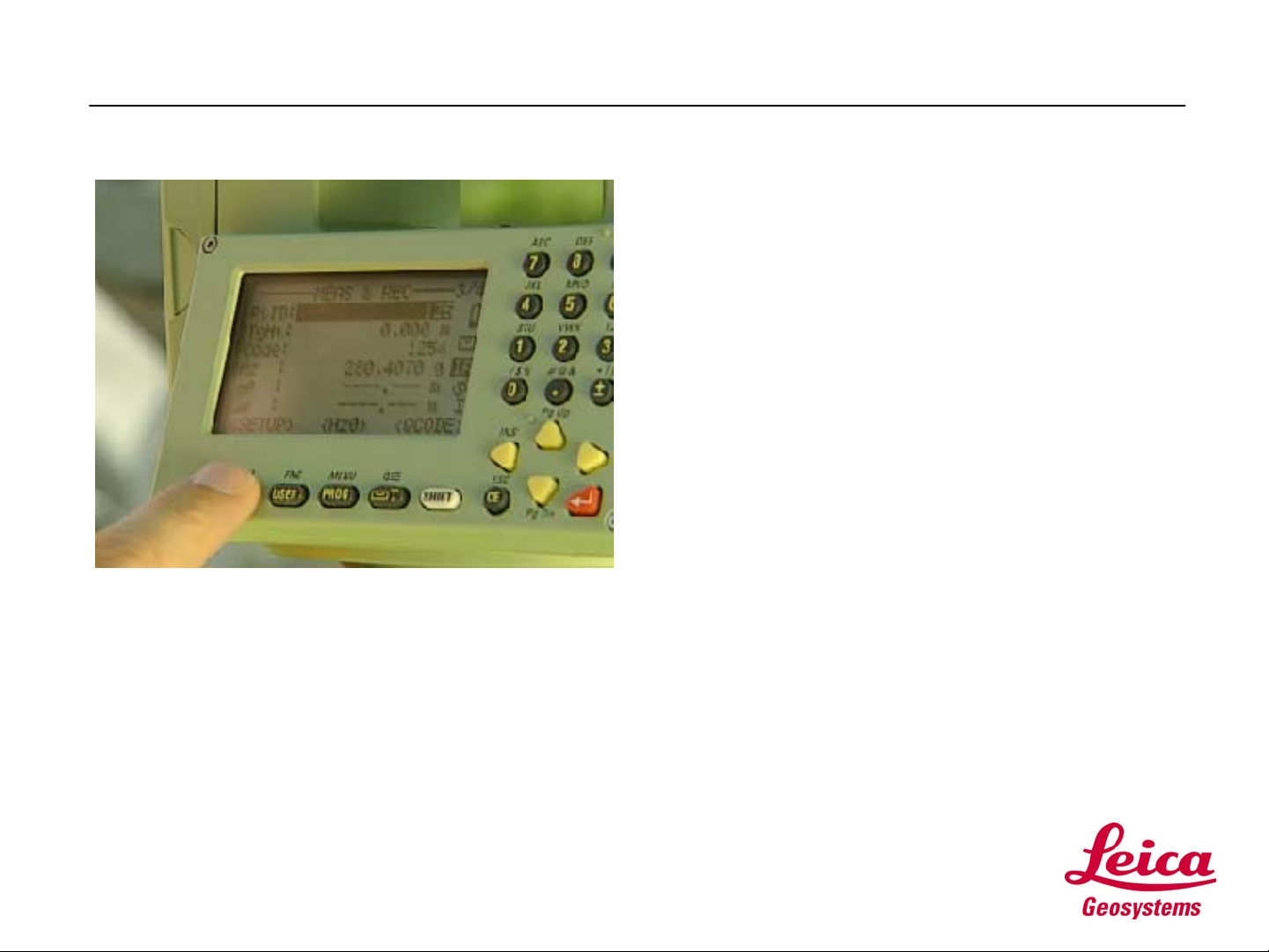
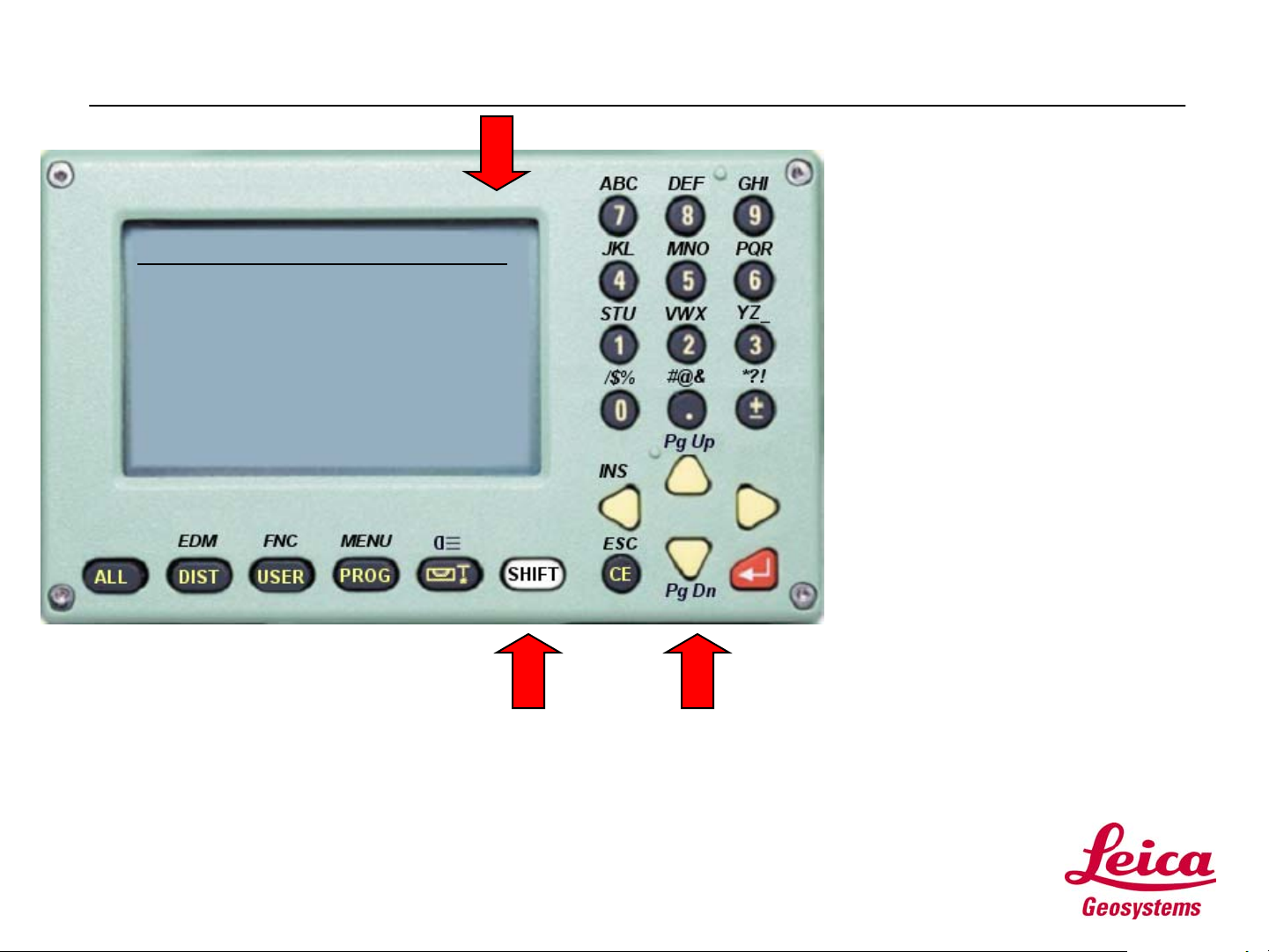
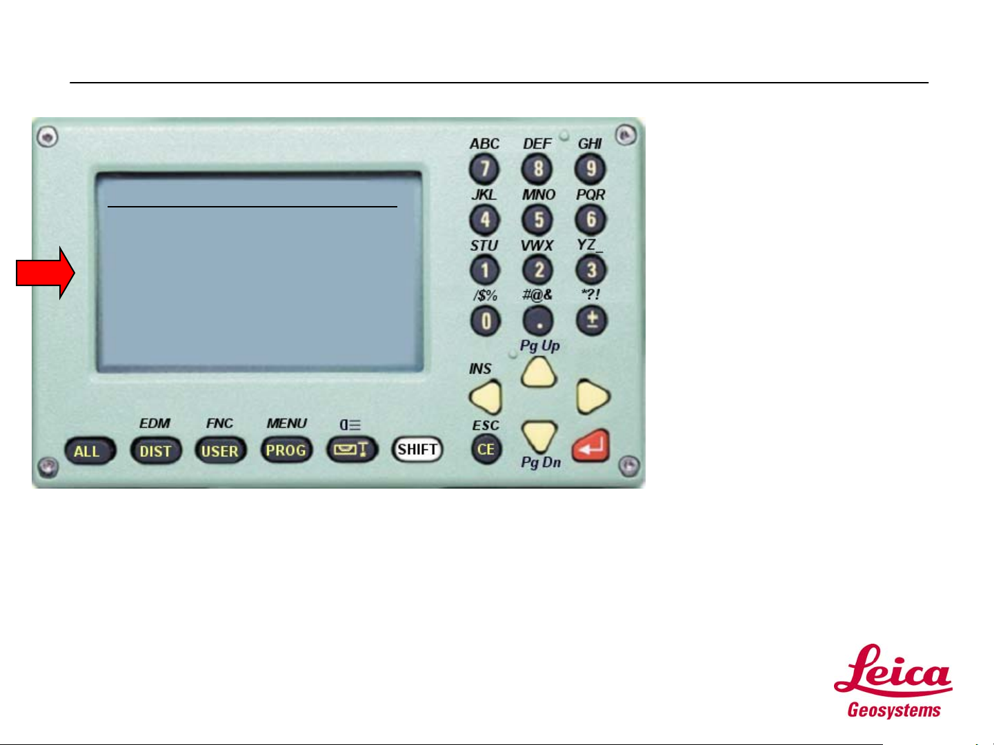
• When you turn your
instrument on, you will see a
screen similar to the one on
the left. This is the Measure
and Record screen.
• To configure your instrument,
you will access the System
Menu.
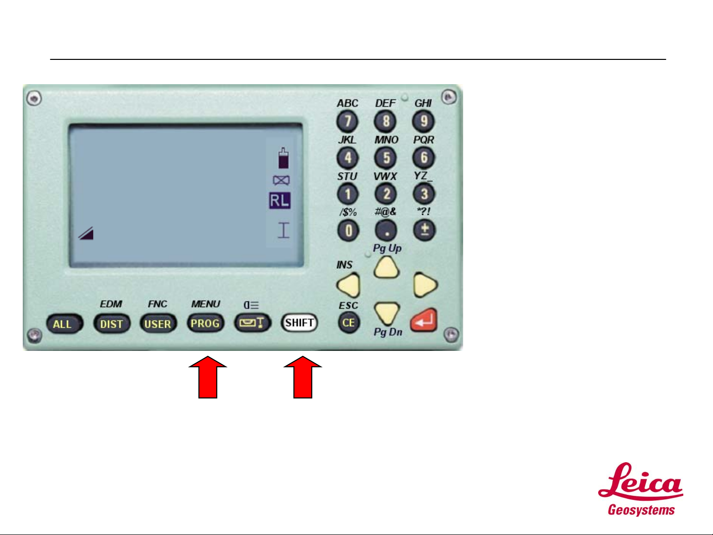
• You’ll notice the MENU label
above the PROG button. T o
access MENU (The System
Menu), press the SHIFT
button, then the PROG button.
• This displays the System
Menu.
• Note: The SHIFT key is used
to access all functions labeled
above a key.
Page 6
Step 1: Configuring
• From the System Menu
screen:
SYSTEM MENU
1 DATA Manager
2 Quick Settings/User-k
3 All Settings
4 Calibration
5 Info
<EXIT> <START-UP>
• Use the Arrow keys to move
the cursor to [3] All Settings,
then press the ENTER key.
• The result is the ALL
SETTINGS Menu.
Page 7
Step 1: Configuring
• From the ALL SETTINGS
MENU:
ALL SETTINGS MENU
1 System Settings
2 Angular & Compensator
3 Measurement Units
4 PC Communications
5 Date & Time
<EXIT> <BACK>
• Use the Arrow keys to move
the cursor to [1] System
Settings, then press the
ENTER key.
• The result is the SYSTEM
SETTINGS screen.
Page 8
Step 1: Configuring
SYSTEM SETTINGS 1/3
Beep Normal
Sector Beep Off
Face I Def. V-Left
Auto OFF Disable
Code record Before
:
:
:
:
:
<EXIT> <BACK> <SET>
ef
ef
ef
ef
ef
• From SYSTEM SETTINGS:
• Use the Arrow keys to make
the settings as displayed in
the figure to the left.
• Note: The symbols ef show
you that you can change a
value by using the right or left
Arrow keys.
• Note that to the right of the
SYSTEM SETTINGS screen
title, the symbol: 1/3. This
signifies that the SYSTEM
SETTINGS screen has three
pages. You are viewing one
of three.
Page 9
• To view succeeding pages on
any screen, just press the
SHIFT key, then the Pg DN
key.
Step 1: Configuring
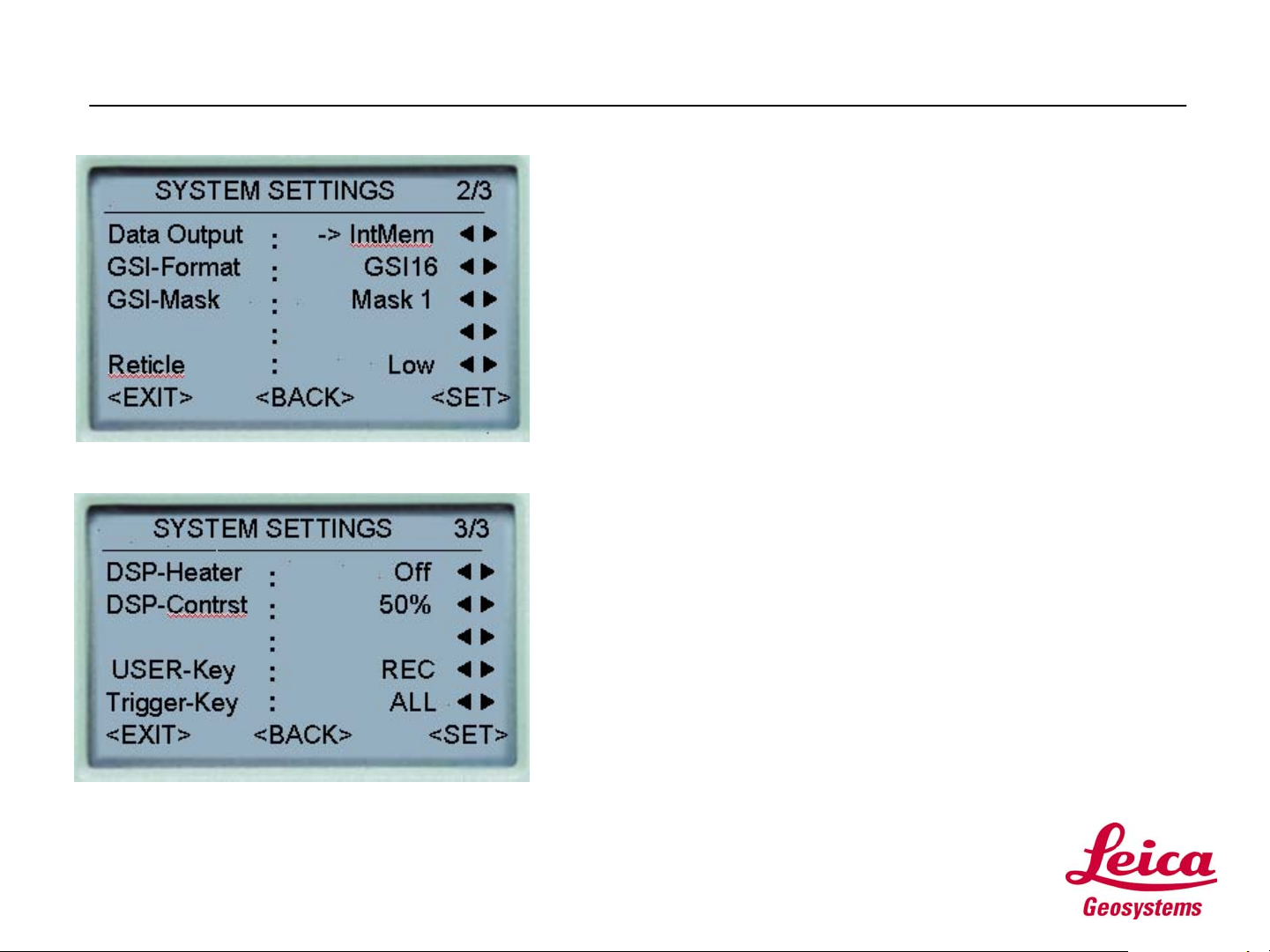
• From SYSTEM SETTINGS:
• Press SHIFT, then Pg DN for page 2/3.
• Make the settings to match those in the figure.
• Then, press SHIFT, then Pg DN for page 3/3.
• Make the settings to match those in the figure.
• When you’ve finished configuring the SYSTEM
SETTINGS, use the Arrow keys to move to SET.
Press the ENTER key to store your settings and
return to the ALL SETTINGS MENU.
• NOTES:
• Data Output is set to Internal Memory. If you were to
use an external hand held data collector, this setting
would be changed to RS232 (serial port) connection.
• The Trigger Key is over the horizontal tangent. We
have set to ALL to both measure and record with one
keystroke.
• The User Key (found on your instrument keyboard) is
set to REC to record codes or measurements.
Page
10

Step 1: Configuring
• From the ALL SETTINGS
MENU:
ALL SETTINGS MENU
1 System Settings
2 Angular & Compensator
3 Measurement Units
4 PC Communications
5 Date &Time
<EXIT> <BACK>
• Use the Arrow keys to move
the cursor to [2} Angular &
Compensator, then press the
ENTER key.
• The result is the ANGULAR
&COMPENSATOR screen.
Page
11

Step 1: Configuring
• From the ANGULAR &
COMPENSATOR menu:
ANGULAR & COMPENSATOR
Tilt Corr. 2-Axis
Hz collim. On
Angle res. 0º00’01”
V setting Zenith
Hz increm. Right
<EXIT> <BACK> <SET>
:
:
:
:
:
ef
ef
ef
ef
ef
• Use the Arrow keys to make
the settings as displayed in
the figure to the left.
• When you’ve finished
configuring the ANGULAR &
COMPENSATOR settings,
use the Arrow keys to move to
SET. Press the ENTER key
to store your settings and
return to the ALL SETTINGS
MENU.
Page
12
Step 1: Configuring
• From the ALL SETTINGS
MENU:
ALL SETTINGS MENU
1 System Settings
2 Angular & Compensator
3 Measurement Units
4 PC Communications
5 Date &
Time
<EXIT> <BACK>
• Use the Arrow keys to move
the cursor to [3}
Measurement Units, then
press the ENTER key.
• The result is the
MEASUREMENT UNITS
screen.
Page
13
Step 1: Configuring
• From the MEASUREMENT
UNITS menu:
MEASUREMENT UNITS
ANGLE 360º ’
”
Distance US-ft-3
Temp. º F
Pressure inHg
<EXIT> <BACK> <SET>
:
:
:
:
:
ef
ef
ef
ef
ef
• Use the Arrow keys to make
the settings as displayed in
the figure to the left.
• When you’ve finished
configuring the
MEASUREMENT UNITS
settings, use the Arrow keys
to move to SET. Press the
ENTER key to store your
settings and return to the ALL
SETTINGS MENU.
• Note: US-ft-3 represents US
Feet with 3 decimal places
and US-ft-2, US Feet with 2
decimal places.
Page
14
Step 1: Configuring
• From the ALL SETTINGS
MENU:
ALL SETTINGS MENU
1 System Settings
2 Angular & Compensator
3 Measurement Units
4 PC Communications
5 Date & Time
<EXIT> <BACK>
• We won’t be making any more
configuration settings at this
time.
• Use the Arrow keys to move
the cursor to EXIT, then press
the ENTER key.
• This will return you to the
Measure and Record screen,
where we started..
Page
15
Step 1: Configuring
• Now is a good time to see if you’re
still on target.
• Please refer to your TPS700auto Self
Study Exercises document.
• Complete all the exercises in the Step 1:
Configuring section.
Page
16

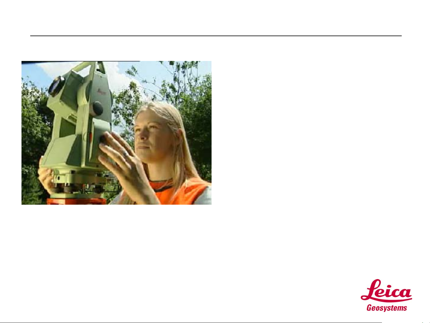
Step 2: Surveying
• Surveying
• In Step 2: Surveying, we’ll take your new
instrument out for a spin.
• We will:
• Make some measurements using ATR, Automatic
Target Recognition, and RL, the reflectorless
EDM.
• Install Leica Survey Office, LSO, the program
used to upload files and data to and from your
instrument and PC.
• Create a list of Codes, used to describe points in
the field, and upload the list to your TPS700auto
using LSO.
• Upload a Format file to your instrument. A Format
file is used to define the format of your field data
as it is downloaded to your computer using LSO.
You can use Format files to output your field data
in many different formats, from a simple ASCII
coordinate file to a DXF file.
• Collect some field data and download it to your
PC with LSO.
Page
17
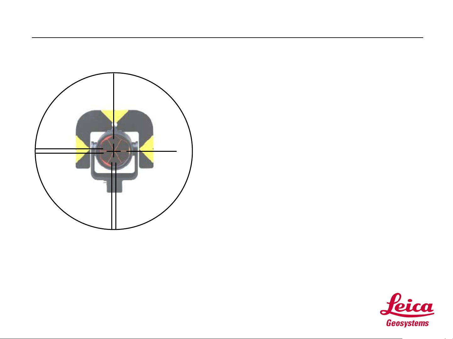
Step 2: Surveying
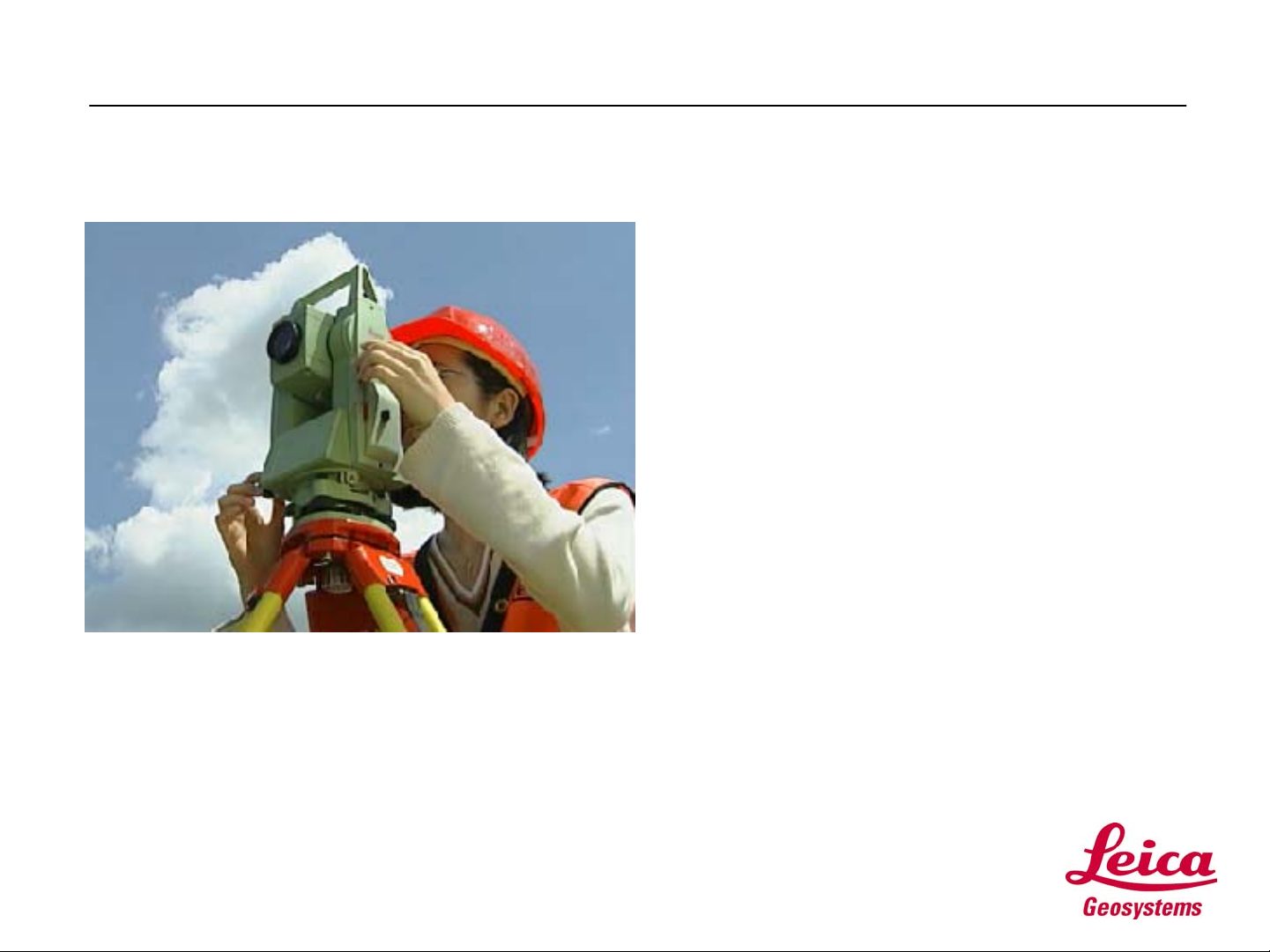
• Making some measurements:
• The best way to learn is by doing. So, let’s do it.
• Pick an area outside, in the parking lot or in the
backyard, suitable for setting up your new total
station and making some measurements.
• You will need a prism and pole and a rodman. If
you don’t have someone to help, set the prism up
on a tripod or bipod.
• Complete Exercise #1 from the Step 2: Surveying
section of your TPS700auto Self Study
Exercises document.
• The exercise will guide you through the
measurement process.
Page
18
 Loading...