

Page 1
TPS700 Performance Series: TPS700auto
Steps
To
Productivity
Page 1
A Leica Advantage Self Study Guide
Page 2
Introduction
• Welcome to “TPS700auto: Three Steps to
Productivity”.
• Three Steps to Productivity is a Leica Advantage
Self Study Guide and is designed to familiarize
you with the key components of your new
TPS700auto Total Station.
• Three Steps to Productivity will not teach you how
to use every feature on board your TPS700auto,
but will get you acquainted with three key functions
on board your instrument which are common to
most of the surveying tasks you are likely to
encounter.
• Once you’ve taken these first three steps, you will
be familiar enough with the operating concepts of
the TPS700auto to step out on your own to use all
of the versatile features of the instrument.
Page 2
Page 3
Before You Start
• Before you start, please read the
following pages from the “TPS700
Performance Series User Manual”
(Version 2.0):
• Introduction, pages 6-11
• Measuring Preparation / Setting Up,
pages 15 – 20, 23-24,
• This study guide will refer to exercises
found in the accompanying document
file, TPS700auto_Exercises.doc.
• Print the file for your self study
workbook, “TPS700auto Self Study
Exercises”.
• The best way to learn to use your new
instrument is to take the time now to
punch the buttons and to work through
the exercises. Good luck and have fun!
Page 3
Page 4

Contents
• Step 1: Configuring
• Step 2: Surveying
Page 4
• Step 3: Setting Out
Page 5
Step 1: Configuring
• Configuring
• There are many ways to configure your
TPS700auto Total Station.
• This Self Study will step you through one way
to do it. It’s not the only way, or necessarily
the best, but will serve as a basis for learning.
• Set your instrument up next to your PC.
• Configure your instrument by following the
directions on the following screens.
Page 5
Page 6
Step 1: Configuring
• Configuring your
TPS700auto:
----------MEAS & REC-----------1/4
Pt Id
TgHt
Hz
V
:
:
:
:
68º44’32”
94 º45”46”
:
100
0.000 m
----.--- m
<SETUP> <Hz0> <QCODE>
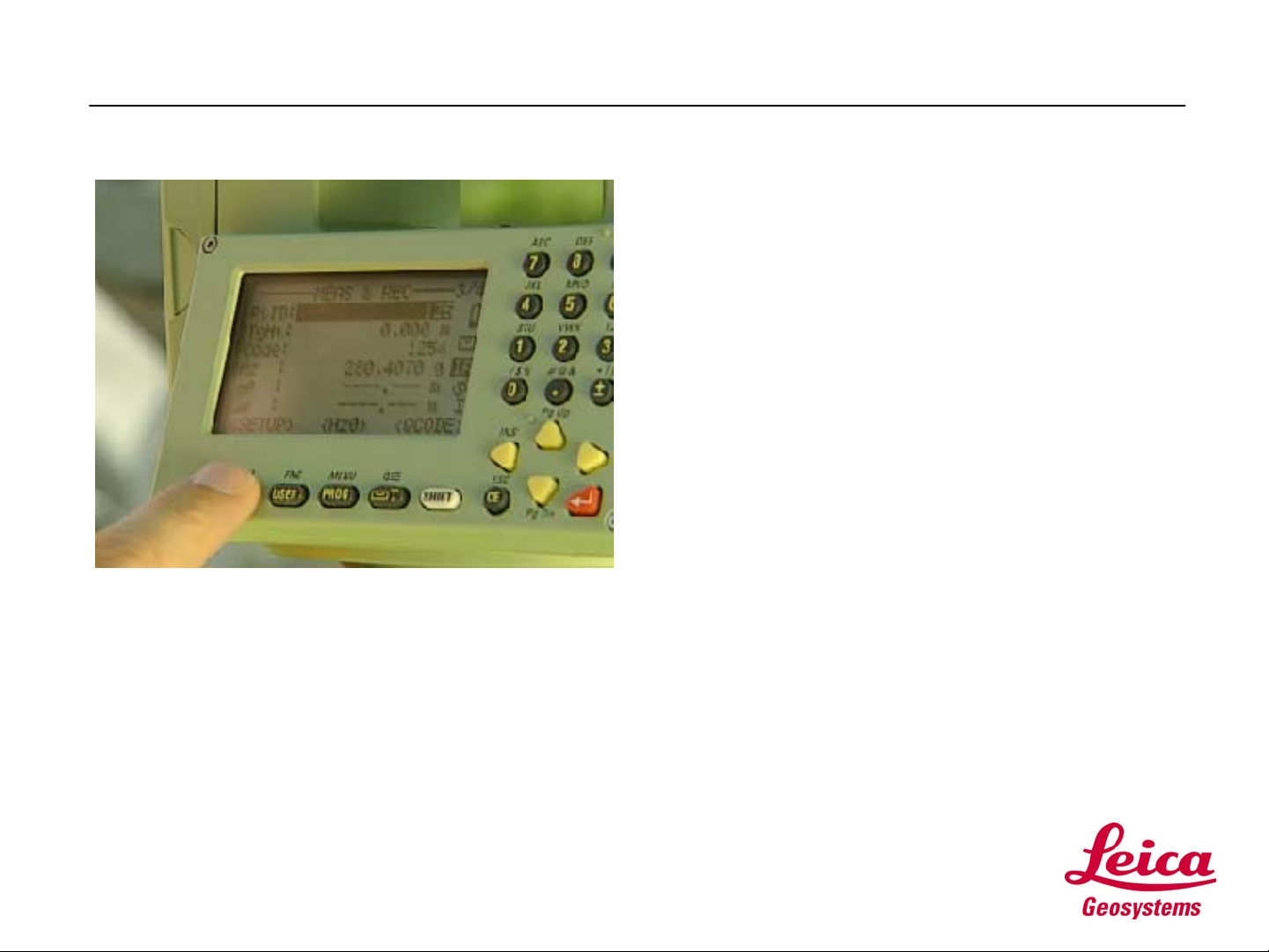
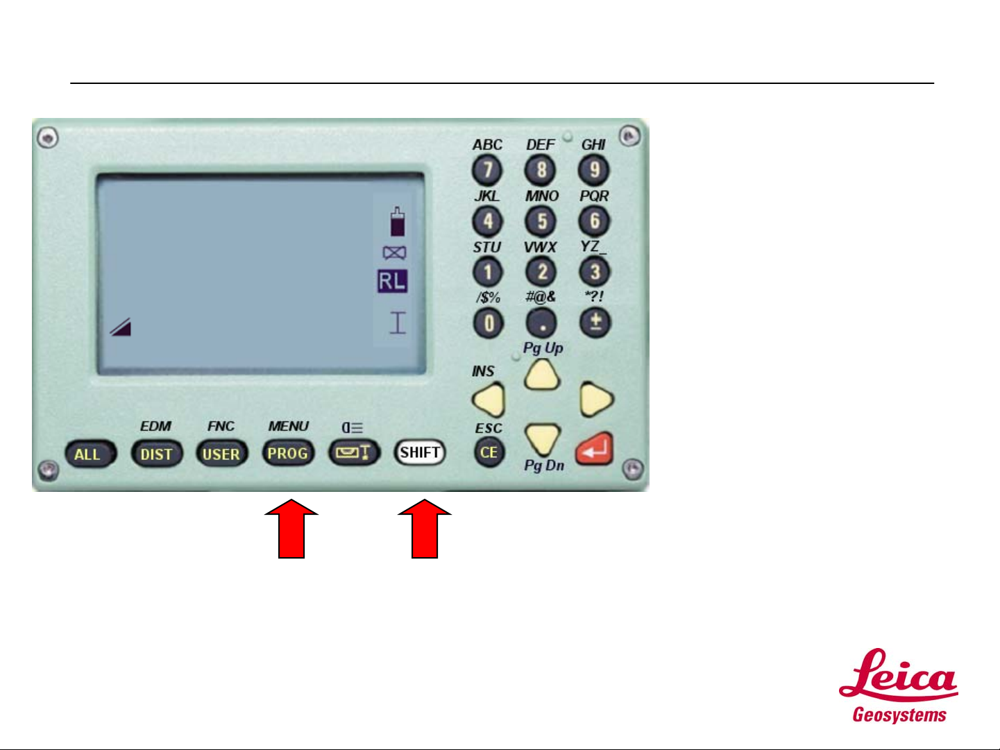
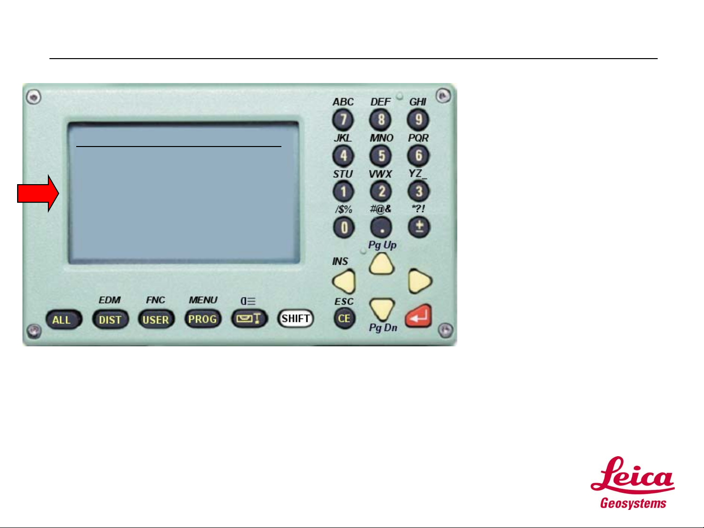
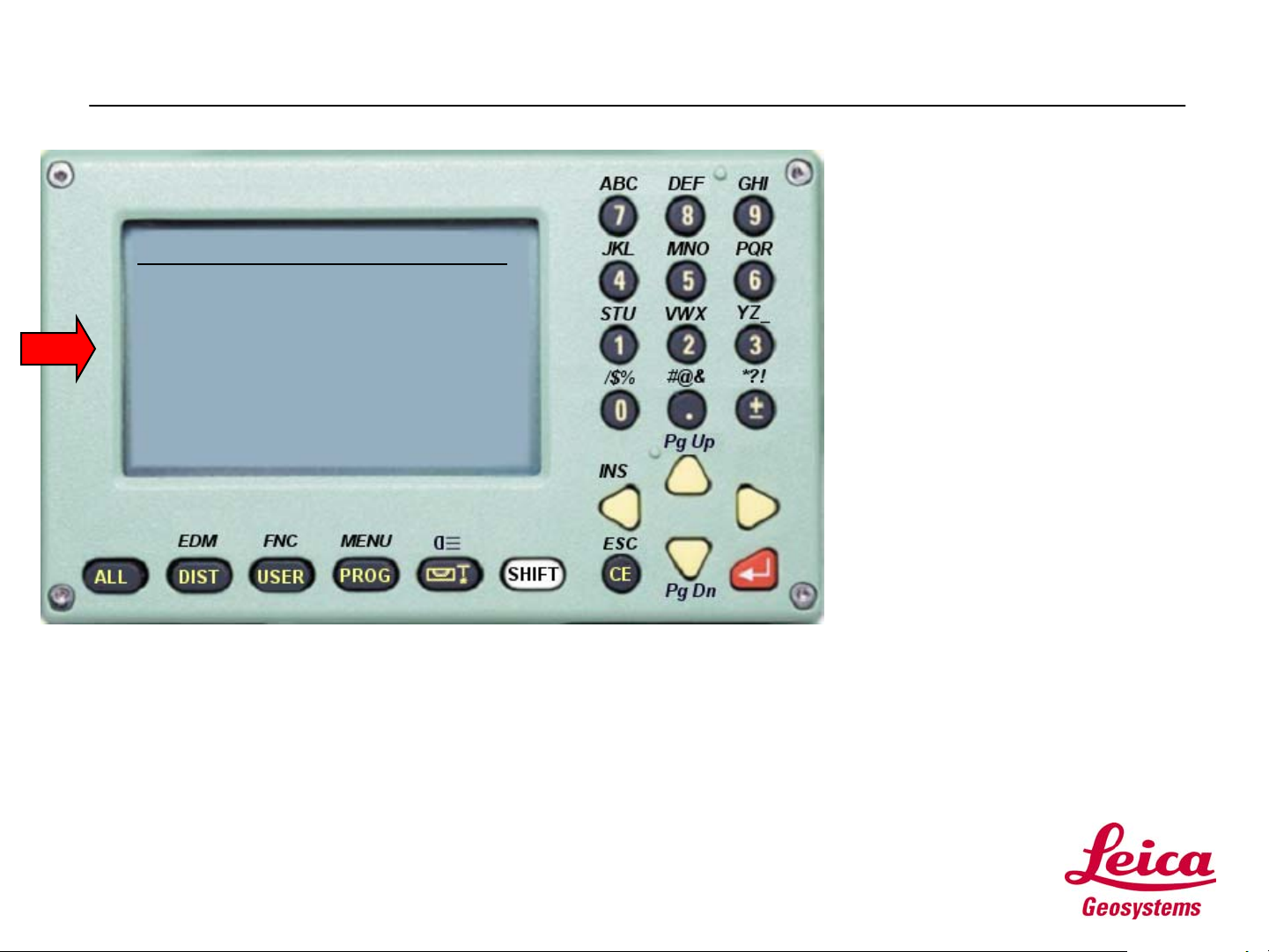
• When you turn your
instrument on, you will see a
screen similar to the one on
the left. This is the Measure
and Record screen.
• To configure your instrument,
you will access the System
Menu.
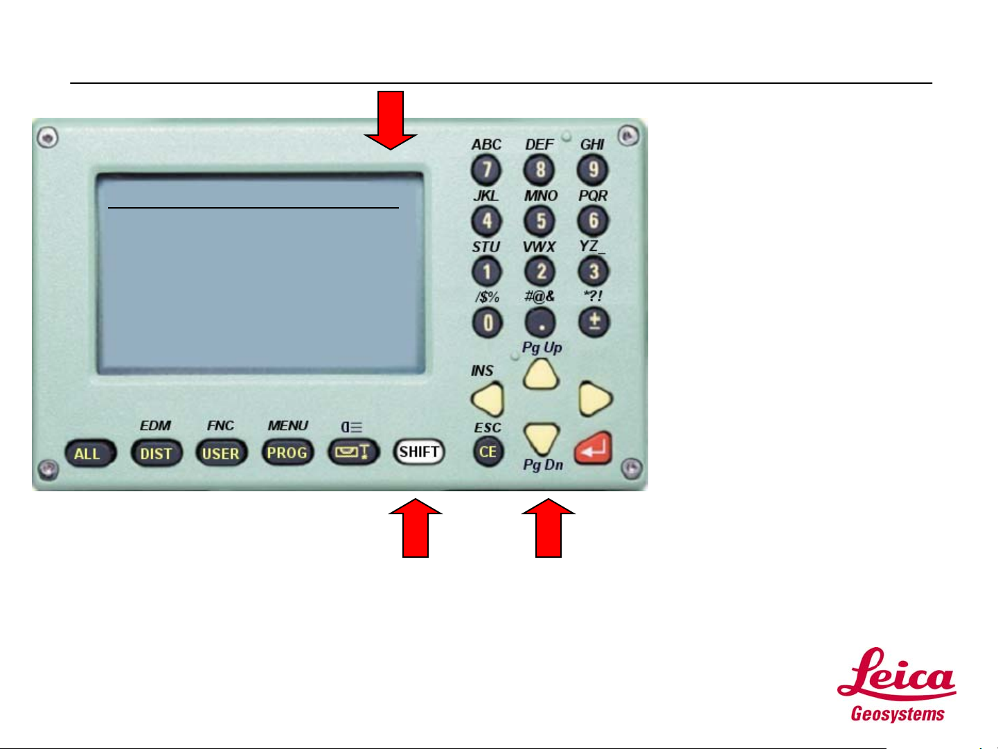
• You’ll notice the MENU label
above the PROG button. T o
access MENU (The System
Menu), press the SHIFT
button, then the PROG button.
• This displays the System
Menu.
• Note: The SHIFT key is used
to access all functions labeled
above a key.
Page 6
Page 7
Step 1: Configuring
• From the System Menu
screen:
SYSTEM MENU
1 DATA Manager
2 Quick Settings/User-k
3 All Settings
4 Calibration
5 Info
<EXIT> <START-UP>
• Use the Arrow keys to move
the cursor to [3] All Settings,
then press the ENTER key.
• The result is the ALL
SETTINGS Menu.
Page 7
Page 8
Step 1: Configuring
• From the ALL SETTINGS
MENU:
ALL SETTINGS MENU
1 System Settings
2 Angular & Compensator
3 Measurement Units
4 PC Communications
5 Date & Time
<EXIT> <BACK>
• Use the Arrow keys to move
the cursor to [1] System
Settings, then press the
ENTER key.
• The result is the SYSTEM
SETTINGS screen.
Page 8
Page 9
Step 1: Configuring
SYSTEM SETTINGS 1/3
Beep Normal
Sector Beep Off
Face I Def. V-Left
Auto OFF Disable
Code record Before
:
:
:
:
:
<EXIT> <BACK> <SET>
ef
ef
ef
ef
ef
• From SYSTEM SETTINGS:
• Use the Arrow keys to make
the settings as displayed in
the figure to the left.
• Note: The symbols ef show
you that you can change a
value by using the right or left
Arrow keys.
• Note that to the right of the
SYSTEM SETTINGS screen
title, the symbol: 1/3. This
signifies that the SYSTEM
SETTINGS screen has three
pages. You are viewing one
of three.
Page 9
• To view succeeding pages on
any screen, just press the
SHIFT key, then the Pg DN
key.
Page 10
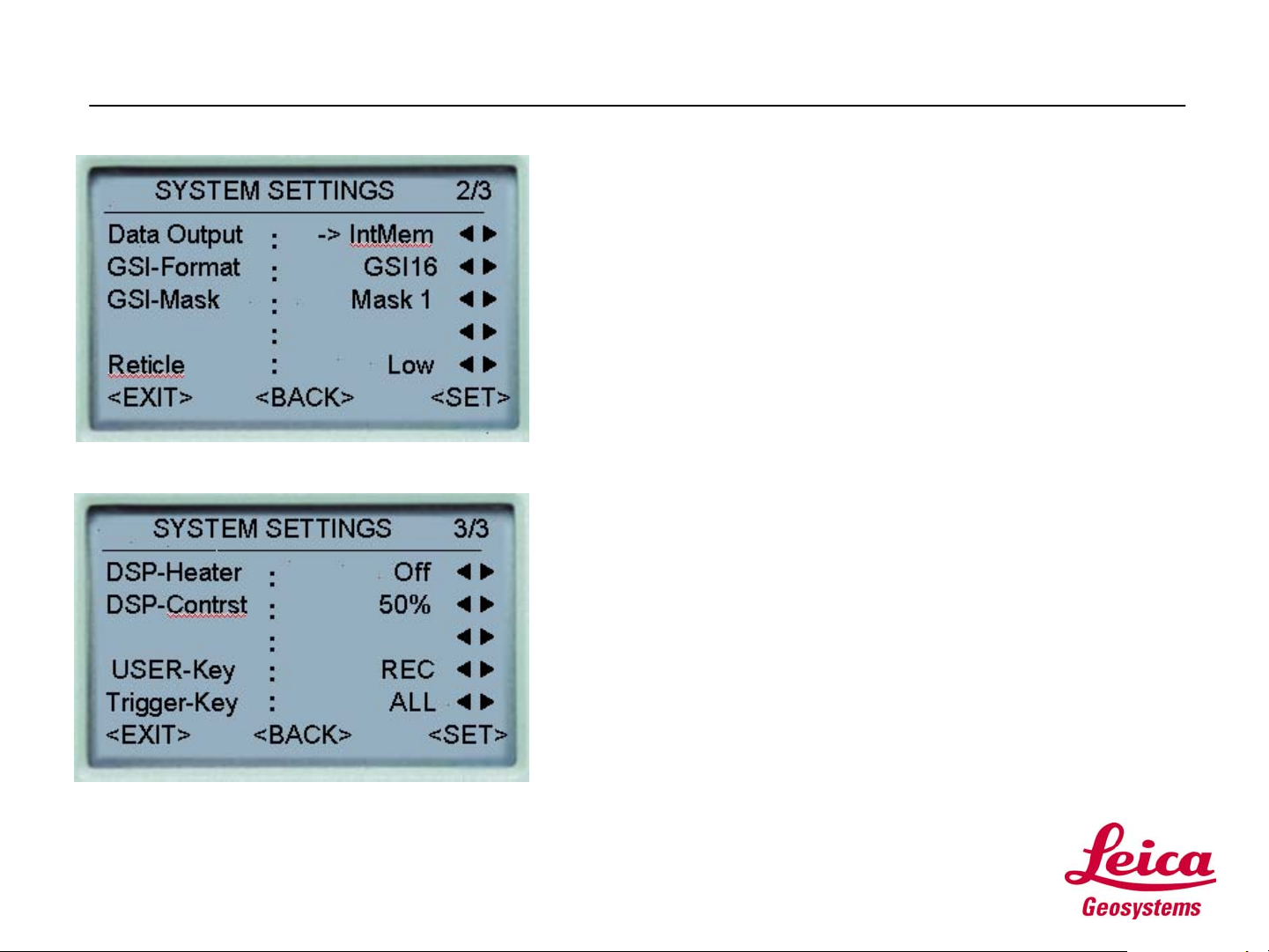
Step 1: Configuring
• From SYSTEM SETTINGS:
• Press SHIFT, then Pg DN for page 2/3.
• Make the settings to match those in the figure.
• Then, press SHIFT, then Pg DN for page 3/3.
• Make the settings to match those in the figure.
• When you’ve finished configuring the SYSTEM
SETTINGS, use the Arrow keys to move to SET.
Press the ENTER key to store your settings and
return to the ALL SETTINGS MENU.
• NOTES:
• Data Output is set to Internal Memory. If you were to
use an external hand held data collector, this setting
would be changed to RS232 (serial port) connection.
• The Trigger Key is over the horizontal tangent. We
have set to ALL to both measure and record with one
keystroke.
• The User Key (found on your instrument keyboard) is
set to REC to record codes or measurements.
Page
10
Page 11

Step 1: Configuring
• From the ALL SETTINGS
MENU:
ALL SETTINGS MENU
1 System Settings
2 Angular & Compensator
3 Measurement Units
4 PC Communications
5 Date &Time
<EXIT> <BACK>
• Use the Arrow keys to move
the cursor to [2} Angular &
Compensator, then press the
ENTER key.
• The result is the ANGULAR
&COMPENSATOR screen.
Page
11
Page 12

Step 1: Configuring
• From the ANGULAR &
COMPENSATOR menu:
ANGULAR & COMPENSATOR
Tilt Corr. 2-Axis
Hz collim. On
Angle res. 0º00’01”
V setting Zenith
Hz increm. Right
<EXIT> <BACK> <SET>
:
:
:
:
:
ef
ef
ef
ef
ef
• Use the Arrow keys to make
the settings as displayed in
the figure to the left.
• When you’ve finished
configuring the ANGULAR &
COMPENSATOR settings,
use the Arrow keys to move to
SET. Press the ENTER key
to store your settings and
return to the ALL SETTINGS
MENU.
Page
12
Page 13
Step 1: Configuring
• From the ALL SETTINGS
MENU:
ALL SETTINGS MENU
1 System Settings
2 Angular & Compensator
3 Measurement Units
4 PC Communications
5 Date &
Time
<EXIT> <BACK>
• Use the Arrow keys to move
the cursor to [3}
Measurement Units, then
press the ENTER key.
• The result is the
MEASUREMENT UNITS
screen.
Page
13
Page 14
Step 1: Configuring
• From the MEASUREMENT
UNITS menu:
MEASUREMENT UNITS
ANGLE 360º ’
”
Distance US-ft-3
Temp. º F
Pressure inHg
<EXIT> <BACK> <SET>
:
:
:
:
:
ef
ef
ef
ef
ef
• Use the Arrow keys to make
the settings as displayed in
the figure to the left.
• When you’ve finished
configuring the
MEASUREMENT UNITS
settings, use the Arrow keys
to move to SET. Press the
ENTER key to store your
settings and return to the ALL
SETTINGS MENU.
• Note: US-ft-3 represents US
Feet with 3 decimal places
and US-ft-2, US Feet with 2
decimal places.
Page
14
Page 15
Step 1: Configuring
• From the ALL SETTINGS
MENU:
ALL SETTINGS MENU
1 System Settings
2 Angular & Compensator
3 Measurement Units
4 PC Communications
5 Date & Time
<EXIT> <BACK>
• We won’t be making any more
configuration settings at this
time.
• Use the Arrow keys to move
the cursor to EXIT, then press
the ENTER key.
• This will return you to the
Measure and Record screen,
where we started..
Page
15
Page 16
Step 1: Configuring
• Now is a good time to see if you’re
still on target.
• Please refer to your TPS700auto Self
Study Exercises document.
• Complete all the exercises in the Step 1:
Configuring section.
Page
16
Page 17
Step 2: Surveying
• Surveying
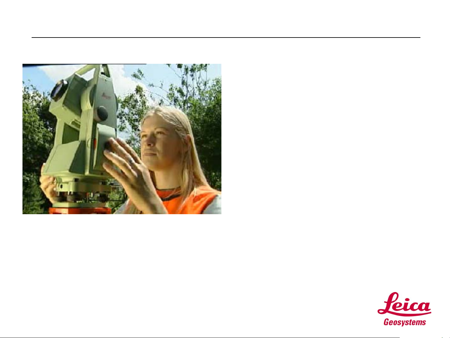
• In Step 2: Surveying, we’ll take your new
instrument out for a spin.
• We will:
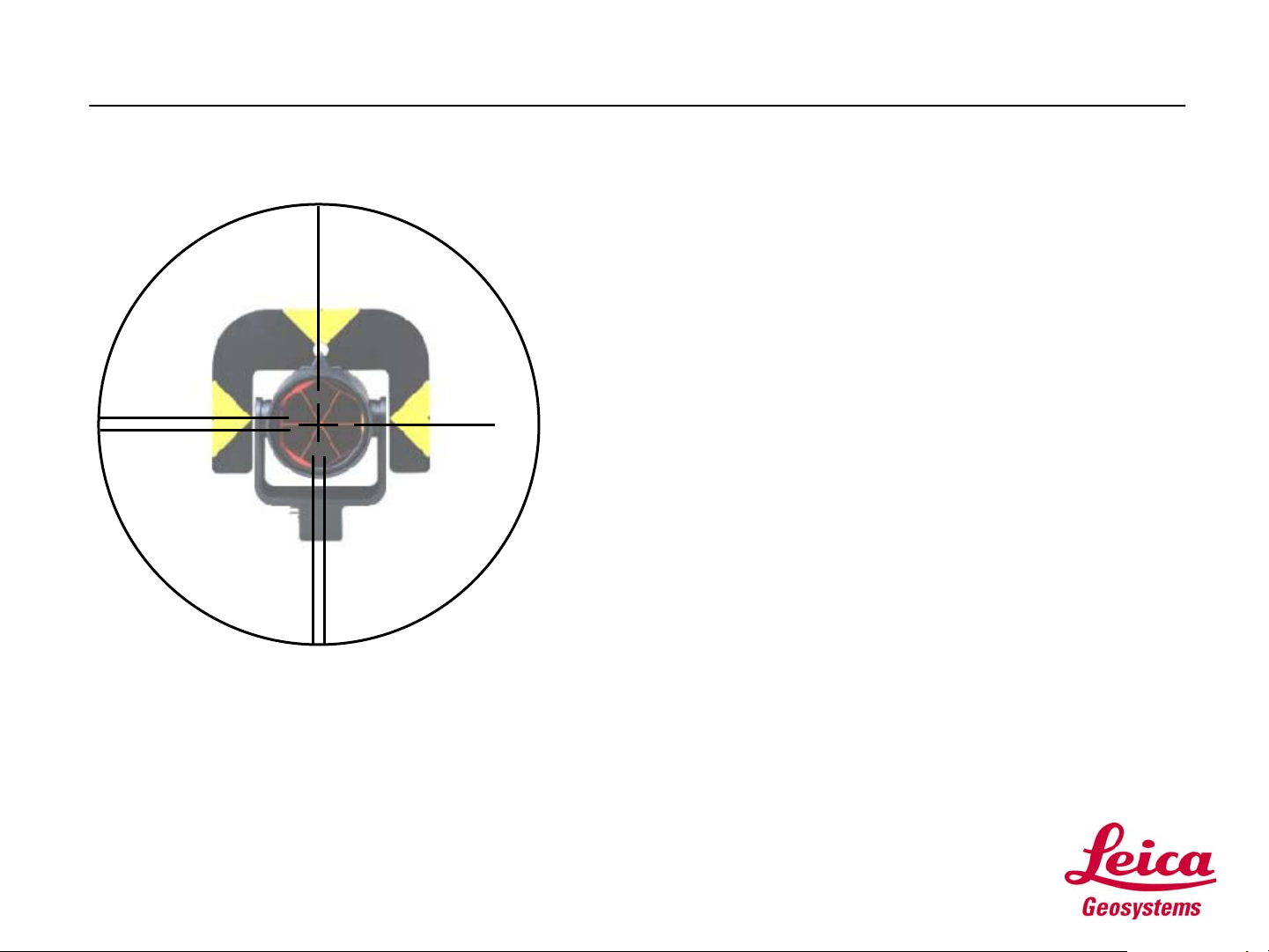
• Make some measurements using ATR, Automatic
Target Recognition, and RL, the reflectorless
EDM.
• Install Leica Survey Office, LSO, the program
used to upload files and data to and from your
instrument and PC.
• Create a list of Codes, used to describe points in
the field, and upload the list to your TPS700auto
using LSO.
• Upload a Format file to your instrument. A Format
file is used to define the format of your field data
as it is downloaded to your computer using LSO.
You can use Format files to output your field data
in many different formats, from a simple ASCII
coordinate file to a DXF file.
• Collect some field data and download it to your
PC with LSO.
Page
17
Page 18
Step 2: Surveying
• Making some measurements:
• The best way to learn is by doing. So, let’s do it.
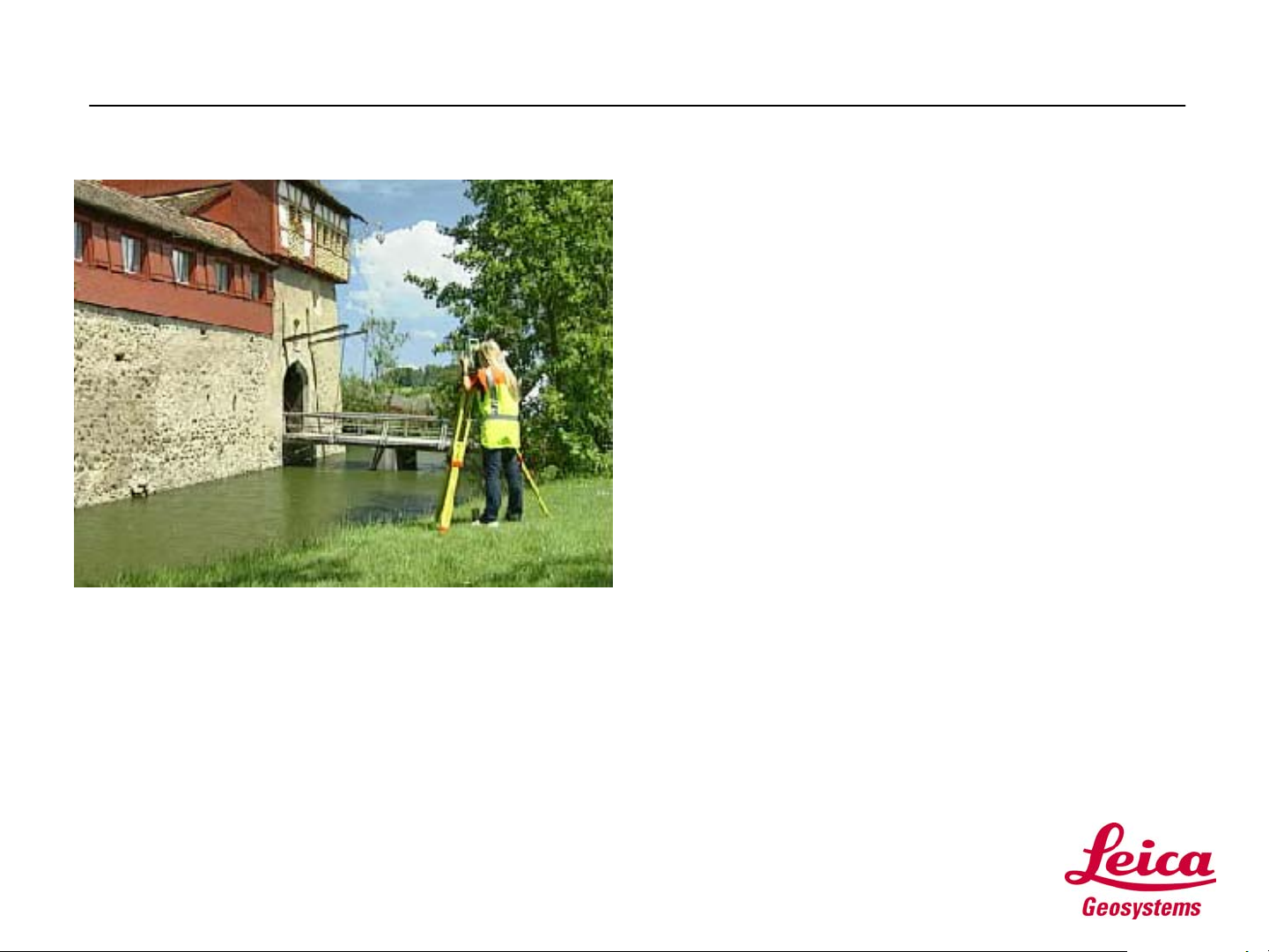
• Pick an area outside, in the parking lot or in the
backyard, suitable for setting up your new total
station and making some measurements.
• You will need a prism and pole and a rodman. If
you don’t have someone to help, set the prism up
on a tripod or bipod.
• Complete Exercise #1 from the Step 2: Surveying
section of your TPS700auto Self Study
Exercises document.
• The exercise will guide you through the
measurement process.
Page
18
Page 19

Step 2: Surveying
• Installing Leica
Survey Office:
• Exercise #2 in your
TPS700auto Self
Study Exercises
document will guide
you through the
installation of the Leica
Survey Office program.
• LSO is found on the
TPS Surveying Series
CD that came with your
instrument.
Page
19
• Please work through
Exercise #2 before
proceeding.
Page 20

Step 2: Surveying
• Creating a Codelist:
• In preparation for doing some data collection,
we will now create a Codelist. Additionally,
you will learn how to upload the Codelist to you
Total Station.
• A Codelist contains descriptors for features
located in the field.
• Please turn to Exercise #3, now.
• Note: You will need the Data Transfer cable
that came with your instrument for this
exercise.
Page
20
Page 21

Step 2: Surveying
• Uploading a Format File:
• A Format file is used to define the format of
your field data as it is downloaded from the
instrument to your computer.
• You can use Format files to output your field
data in several different formats.
• You can create your own Format file or use
one of the predefined Format files.
• The file NEHC.frt is a format file that is
distributed with Three Steps to Productivity.
• You are already familiar with the Data
Exchange Manager, so uploading a Format file
should be easy.
• Please work through Exercise #4 to learn how
to upload a format file.
Page
21
Page 22

Step 2: Surveying
• Field to Finish:
• You are ready to collect field data. In this
exercise you will use the onboard
Surveying application program to:
• Collect some points in the field,
• Assign Codes to these points,
• Download the data using a format file and
Leica Survey Office
• So, put on your boots and turn with me now to
Exercise #5.
Page
22
Page 23

Step 3: Setting Out
• Setting Out
• In this section you will learn how to use the Setting
out application program.
• You have already used another application
program, Surveying, in Step 2.
• You will find that the TPS700auto programs all
have a similar interface. If you are comfortable
using one program, running another will come
very easy to you.
• In Step 3, on the following screens and in
Exercise #1, you will learn how to store some
points in the Fixed Points area of your Job.
• In Exercise #2, in the Self Study Exercises
document, you will have the opportunity to go
outside and stake out these points with the Setting
Out program.
Page
23
Page 24

Step 3: Setting Out
----------MEAS & REC-----------1/4
Pt Id
TgHt
Hz
V
<SETUP> <Hz0> <QCODE>
:
:
:
:
:
68º44’32”
94 º45”46”
100
0.000 m
----.--- m
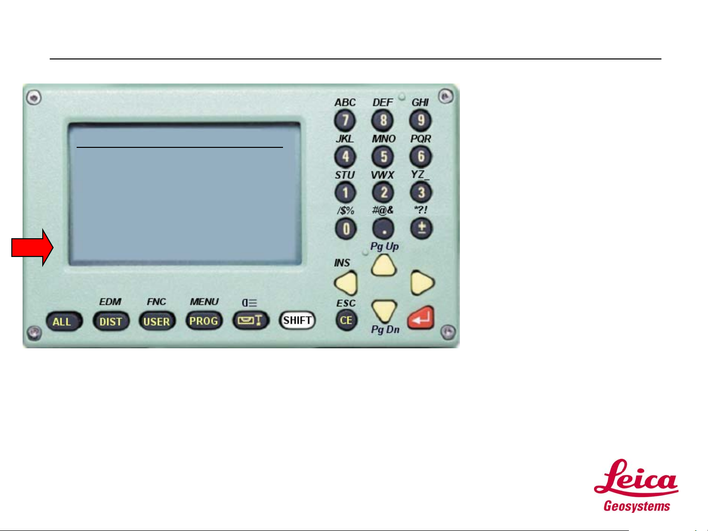
• Input Points:
• From the Measure and
Record screen, press
SHIFT, then MENU.
• The System Menu is
Displayed
Page
24
Page 25

Step 3: Setting Out
• From the System Menu
screen:
SYSTEM MENU
1 DATA Manager
2 Quick Settings/User-k
3 All Settings
4 Calibration
5 Info
<EXIT> <START-UP>
• Use the Arrow keys to move
the cursor to [1] DATA
Manager, then press the
ENTER key.
• The result is the DATA
Manager screen.
Page
25
Page 26

Step 3: Setting Out
• From the DATA Manager
screen:
DATA Manager
1 Meas/Code/Job/Fix
2 Clear Memory
3 Memory Information
4 Download to PC
<EXIT> <BACK>
• Use the Arrow keys to move
the cursor to [1]
Meas/Code/Job/Fix, then
press the ENTER key.
• The VIEW/ADD/DEL/EDIT
DATA screen is displayed.
Page
26
Page 27

Step 3: Setting Out
VIEW/ADD/DEL/EDIT DATA
1 Measurements
2 Codes
3 Jobs
4 Fixpoints
<EXIT> <BACK>
• From the
VIEW/ADD/DEL/EDIT DATA
screen:
• Since our objective is to input
points in the Fixpoints area of
our Job, use the Arrow keys to
move the cursor to [4]
FIXpoints, then press the
ENTER key.
• The FIXPOINT screen is
displayed.
Page
27
Page 28

Step 3: Setting Out
--FIXPOINT--< 1/1>--
Job LEICA
Find Ï
PtID ---- ---N ---- ----
E ---- ---H ---- ----
:
:
:
:
:
:
<EXIT> <DEL> <NEW/EDIT>
ef
ef
• From the FIXPOINT screen:
• To input a new point, use the
Arrow keys to move the cursor
to <NEW/EDIT>, then press
the ENTER key.
• The NEW FIXPOINT screen
is displayed.
Page
28
Page 29

Step 3: Setting Out
NEW FIXPOINT
Job LEICA
PtID 1
N 1000.00
E 1000.00
H 500.00
<EXIT> <BACK> SAVE>
:
ef
:
:
:
:
• From the NEW FIXPOINT
menu:
• Refer to the list of points in
Exercise#1 in the TPS700auto
Self Study Exercise document.
• In the New FIXPOINT screen,
make sure you've selected the
LEICA Job.
• Enter the point ID and its
coordintaes for the first point on
the list, then select <SAVE>.
• The point will be saved to the
Fixed points area and you will be
returned to the NEW FIX POINT
screen to enter a new point.
Page
29
• Enter all 10 points from the list in
Exercise #1.
• NOTE: The coordinates of the
points listed in exercise #1 are in
US FT. Don't forget to change
units!
Page 30

Step 3: Setting Out
• Field Exercise:
• Ready to set out some points?
• Please refer to Exercise #2 for
the procedure for using the
Setting Out application
program.
• You use the points you justed
stored in the instrument in this
exercise.
Page
30
Page 31

Step 3: Setting Out
• You have just completed TPS700auto: Three Steps
to Productivity Self Study.
• It is our hope that you now have a good basic
understanding of the operation of your new
TPS700auto and that you will enjoy a creative and
productive career with it.
Page
31
Page 32

g
TPS Surveyin
TPS700auto
Three Steps to
Productivity
Self Study Exercises
December, 2001
Page 33

Table of Contents
TPS 700auto Self Study Exercises - Introduction.....................................................................................3
Step 1: Configuring...................................................................................................................................4
Step 2: Surveying .....................................................................................................................................7
Step 3: Staking Out.................................................................................................................................25
Continued on next page
TPS 700auto – 3-Steps to Productivity
Exercises
Dec, 2001
Page 2/27
Page 34

TPS 700auto Self Study Exercises - Introduction
Overview
The following exercises accompany “TPS700auto: Three Steps to
Productivity ”
This Leica Advantage Self Study Guide is distributed on the
Leica Advantage web site in a compressed file, “Three Steps
to Productivity.zip” . The following files are contained in
the zip file:
• TPS700auto 3 Steps to Productivity.ppt
• TPS700auto_Exercises.doc
• NEHC.frt
The Self Study Guide presentation and these Exercises will
familiarize you with the basic operation of your new
instrument.
Make sure you take the time to do the exercises. Each
exercise reinforces key concepts covered in the self study
guide.
After you’ve completed the “TPS700auto: Three Steps to
Productivity ” Self Study Guide and Exercises, you will know
enough about the instrument to delve deeper into many of its
features, which will allow you to work more confidently, more
precisely and more productively.
Continued on next page
TPS 700auto – 3-Steps to Productivity
Exercises
Dec, 2001
Page 3/27
Page 35

Step 1: Configuring
Introductio
n
Exercise 1
The purpose of the following exercises is to review what you
have just learnt about configuring your TPS700auto instrument.
Review the configuration settings we just made in the ALL
Settings Menu. List any changes you would make for your day
to day use.
My Configuration Settings
1
2
3
4
5
6
Exercise 2
TPS 700auto – 3-Steps to Productivity
Exercises
• Change the User Key to ATR.
• Go to the Measure and Record Screen.
Question?
• What happens when you Press USER, then the DIST key?
• (Change the User Key back to REC)
In the box below write down the answer to the question.
Continued on next page
Dec, 2001
Page 4/27
Page 36

Exercises in Configuring your TPS700auto,
Continued
Exercise 3
List all the distance units’ settings available on the instrument and give the definition
for the setting.
• (Hint: If you’re not sure, change the setting, then
view the Measure and Record Screen.)
Distance Unit Setting Description
Exercise 4
What important information is displayed in the SYSTEM INFO
screen?
Continued on next page
TPS 700auto – 3-Steps to Productivity
Exercises
Dec, 2001
Page 5/27
Page 37

Exercises in Configuring your TPS700auto,
Continued
Exercise 5
Exercise 6
Set the Date and Time on your instrument
To use an external hand held data collector, you must make two settings on your
instrument. Please view these settings screens, now:
Step Action
1
2
Go to the PC Communications screen (in ALL SETTINGS). These
communication parameters must match the communications pa rameters
on the hand held data collector. Most data collectors have options that
let you select your Leica instrument and com settings
In System Settings, change the Data Output field to RS232. This
instructs the instrument to send data to the RS232 po rt, where the data
collector cable connects to the instrument.
Continued on next page
TPS 700auto – 3-Steps to Productivity
Exercises
Dec, 2001
Page 6/27
Page 38

Step 2: Surveying
Exercise 1: Making some measurements
Introductio
n
Measuring
with ATR
The purpose of the exercise is to see what your TPS700auto can do. Set your
instrument up outdoors. If possible, have someone carry a prism and pole for you.
You will need a watch.
To get a feel for ATR, Automatic Target Recognition, follow the procedures below.
Step Action
1
2
3
4
Record your times here:
Finish Time
Total Time for 10
Setup the instrument up and level it.
Turn the instrument on. The Measure and Record screen is displayed.
In the Measure and Record Screen, enter a point ID, then press Enter.
Using your rodman, manually locate 10 points about 100 feet from the
instrument:
• Mark the Start time when the rodman is on the first point.
• Manually place the crosshairs on the target at each point, as
you would normally.
• Then press the DIST key.
• After locating the last point, record the Finish time
• Record your Start and Finish times in the table, below.
Manual Pointing
Start Time
Points
Continued on next page
TPS 700auto – 3-Steps to Productivity
Exercises
Dec, 2001
Page 7/27
Page 39

Exercise 1: Making some measurements, Continued
Step Action
5
Record your times here:
Finish Time
Total Time for 10
Now locate the same 10 points using ATR:
• First, turn ATR on:
o Press SHIFT, then the FNC (Function) key.
o Press SHIFT, then the PG Dn (down arrow) key.
o Use the arrow keys to go to menu selection (8), ATR
On/Off
o Prees Enter to turn ATR ON (Note that this selection is
merely a toggle, select it again to toggle ATR OFF)
o The Measure and Record Screen is displayed. Notice
the ATR icon (a circle and arrow) indicating ATR is on.
• When the rodman is on the first point, mark your Start time.
• Use the peep sight to aim the telescope. You only need to put
the target in the telescope’s field of view.
• Press the dist key to activate ATR and and a distance
measurement.
• After locating 10 points, record your Finish time in the table
below.
Turn ATR off.
ATR Pointing
Start Time
Points
TPS 700auto – 3-Steps to Productivity
Exercises
Compare the total times for surveying the ten points in manual
mode and ATR mode. Write down the difference in the box below.
This is your productitivity gain.
Continued on next page
Dec, 2001
Page 8/27
Page 40

Exercise 1: Making some measurements, Continued
Using the
Reflectorle
ss EDM
Now try out the reflectorless EDM. Try getting a distance to several different
surfaces. In the table below, note the various objects, their attributes and the
distance achieved. See how small an object you can locate. Try the corner of an
overhang or a pole, or something of that nature. These trials will give you a general
idea of what you can use the reflectorless EDM for.
To switch form IR (infrared EDM) to RL (red laser targetless):
• From the measure and Record screen, press SHIFT, then FNC.
• Highlight selection (1) EDM IRÙRL
• Press the ENTER key to toggle RL to ON.
Notice the RL icon signifying that the red laser targetless EDM mode is ON.
Record several of the objects that you were able to make targetless readings to
here:
Object Color Texture Distance
List 3 objects that you were not able to measure with the
reflectorless EDM
Object Color Texture Distance
Continued on next page
TPS 700auto – 3-Steps to Productivity
Exercises
Dec, 2001
Page 9/27
Page 41

Exercise 1: Making some measurements, Continued
Using the
Reflectorle
ss EDM
Quick Tips…
Here are a few features that come in handy:
• From the Meaure and Record screen, press SHIFT, then EDM for the EDM
Settings screen. Take a look at the various EDM and Prism selections.
• RL-Short is the reflectorless EDM. Do not use a prism in the RL-Short mode.
RL-Prism is for long range red laser measurements to a reflector. You can
achieve a 5000m shot to a single prism in RL-Prism.
• Set the EDM Mode to IR Fine, then look at the Prism Trpe selections, using your
arrow key. The prisms listed are the Leica Round, 360, and mini prisms. There
is also a User prism available. If you have another manufacturers prism you
can use it with your TPS700auto. Just set the Prism Constant.
Note:
• The Leica Prism Constant is not the same as a prism
offset. A constant value of –34mm (the offset for a
Leica Round prism) is applied to each value.
Therefore, a Leica Round prism with a prism offset of –
34mm has a Prism Constant of 0.
This looks more confusing than it really is: If you have a prism with a –
30mm offset, input a Prism Constant of +4. ( -30mm –(-34mm) = + 4mm).
Continued on next page
TPS 700auto – 3-Steps to Productivity
Exercises
Dec, 2001
Page 10/27
Page 42

Exercise 2: Installing Leica Survey Office
Introductio
n
Installatio
n
This exercise shows you how to install and Set Up the Leica Survey Office program.
Follow these steps to install the software:
Step Action
1
2
3
4
5
6
7
8
9
10
11
12
Place the TPS Surveying Series CD that came with your instrument in
your CD drive.
When the Welcome screen appears, select “Install Survey Office”.
A new dialog box will appear. Select the appropriate language, then
press the Next button.
A new dialog box will appear encouraging you to shut down all other
applications. Do so, then press Next.
The Software License Agreement is displayed. After you’ve read it and
agree, press YES.
The Select Application Path box appears, accept the default path.
Press Next.
The Setup Type dialog box is displayed. Select Typical, then press
Next.
From the Select Components screen, check:
• TPS300&700 Tools and
• Leica Tools
Then press Next.
In the Select Program Folder dialog box, accept the default folder, Leica
Survey Office, then press Next.
In the Start Copying Files dialog box, select Next.
The program is copied to your PC , then the Setup Complete screen is
displayed. Check the Start Leica Survey Office box, then press Finish.
The LSO main screen is now displayed.
Continued on next page
TPS 700auto – 3-Steps to Productivity
Exercises
Dec, 2001
Page 11/27
Page 43

Exercise 2: Installing Leica Survey Office,
Continued
Set-Up
From the LSO main screen, you will notice seven menu selections:
• Data Exchange Manager: Used transfer data and Codes to and from the
instrument and PC.
• Codelist Manager: Used to build Codelist files containing your descriptor
codes.
• Software Upload: Used for uploading software upgrades and updates to
your instrument.
• Coordinate Editor: Used for building, importing and translating coordinate
data
• Register: Used to configure LSO for your instrument.
• Settings: Used to configure communication parameters for your PC and
instrument.
• External Tools: Used to link programs to LSO for easy access.
In the following steps, you will learn how to set up LSO using the Register and the
Settings menus.
Step Action
1
2
3
4
5
6
7
8
9
Click on the big red Register button.
A pop window is displayed. Select Instruments.
The Register Instruments dialog box is displayed.
Highlight your TPS700auto instrument in the right hand Leica Instrument
window, then press the “>” button to register your instrument.
Your instrument is displayed in the Installed Instruments window. Click
the OK button to return the LSO main screen.
Now, click the big red Settings button. The General Settings dialog box
is displayed.
In the General Settings dialog box, under Current Selection:
• make sure that the proper Port is selected. This is the
communications port (serial port) on your PC that you will use to
transfer data.
• Also, make sure that your instrument is selected on the
Instrument list.
In the General Settings dialog box, under Setiings:
• Use the default communications settings
• These values match your instrument’s default settings
Press the OK button to save the settings and return to the LSO main
screen.
Note: The next exercise will use the LSO Codelist Manager.
Continued on next page
TPS 700auto – 3-Steps to Productivity
Exercises
Dec, 2001
Page 12/27
Page 44

Exercise 3: Creating a Codelist with Leica
Survey Office
Introductio
n
Codelist
Name
Needed
Codes
In this exercise we will create and upload a Codelist in Leica Survey Office.
We’ll name this codelist: LEICA
We’ll create a sample codelist with the following seven codes:
Code Description Attributes Short Cut
NAIL Nail None 10
TREED Deciduous Tree
TLSP Top of Slope
BSLP Bottom of Slope
HSE House
SSMH Storm Sewer
Manhole
TRAV FS to Trav Pt.
• Diameter
(Mandatory, Real)
• Spread (Normal,
Real)
• Height (Normal,
Real)
• None
• None
• Civic # (Normal,
Integer)
• # of Stories
(Mandatory,
Integer)
• Invert In
(Mandatory,Intege
r)
• # FS Points
(Mandatory,
Integer)
• # of Arcs
(Mandatory,
Integer)
Continued on next page
11
12
13
20
None
None
TPS 700auto – 3-Steps to Productivity
Exercises
Dec, 2001
Page 13/27
Page 45

Exercise 3: Creating a Codelist with Leica
Survey Office, Continued
Procedure
Use the following steps to create the Codelist.
Step Action
1 From Leica Survey Office main screen, select Code
2 From the Codelist Manager Screen, select File, then
3 From the Codelist Type dialog box, select TPS700 as
4 Press OK
5 In the New Codelist box, type in the new Codelist
6
7 Refer to the list of Codes, above. In the New
8 Press OK to save the new code.
9 Now, let’s enter the next code: Click on the Code
List Manager.
New.
the Instrument Class and set the Codelist Type to
Advanced.
Name: “Leica ” , type your name into the Author
field, then press OK. The Codelist – Leica.crf
dialog box is displayed.
Right click on CodeList icon:
New / New Code. The New Code dialog box is
displayed.
Codelist dialog box, Enter NAIL in the Code Field, 10
in the Short Cut field, and Nail in the Description
field.
, then select
icon:
10 As before, enter TREED in the Code Field, 11 in the
Short Cut field, and Deciduous Tree in the
Description field.
11 To enter Attributes, first expand the Leica Codelist
by clicking on the
12 When your Codelist expands, click on your code,
13 Enter Diameter in the Attribute Name field, Mandatory
for Attribute Type, Real in the Value Type field, and
None for Default Value.
14 Press Enter in the Attribute Name Field to Enter the
remaining Attributes.
15 Enter the remaining Codes from the list above by
repeating the procedure beginning at step 6.
for the New Code dialog box.
icon.
for the Attribute entry fields.
• Diameter (Mandatory, Real)
• Spread (Normal, Real)
• Height (Normal, Real)
Continued on next page
TPS 700auto – 3-Steps to Productivity
Exercises
Dec, 2001
Page 14/27
Page 46

Exercise 3: Creating a Codelist with Leica
Survey Office, Continued
Step Action
16 Save your new Codelist:
• From the Codelist Manager Screen, select File,
then Save.
• Sava As dialog box, make sure the Codelist Name
and the Directory fields are right.
• Press the OK button to store the file
Leica.crf. (Please remember in which Folder
you saved the file)
17 Close the Codelist Manager program. This returns you
to the LSO main screen.
Continued on next page
TPS 700auto – 3-Steps to Productivity
Exercises
Dec, 2001
Page 15/27
Page 47

Exercise 4: Uploading a Codelist
Uploading
your
Codelist
In this exercise we will upload your new Codelist, Leica.crf,
to the TPS700auto.
.
Step Action
1 Connect your TPS700auto instrument to your PC with
the data upload cable that came with your instrument.
2 From the Leica Survey Office main screen, click on
the Data Exchange Manager Button. The program will
search for your instrument. When communication is
established the following screen is displayed:
Note:
Set the File Filter to Codelists (*.crf)
TPS 700auto – 3-Steps to Productivity
Exercises
Continued on next page
Dec, 2001
Page 16/27
Page 48

Exercise 4: Uploading a Codelist, Continued
Step Action
3 In the illustration above, a TCR702auto is connected
to the PC’s Com port 1. Click the + next to the
TCR702auto to expand the instrument:
The Codelists, Jobs, and Formats are folders onboard
the TCR702auto.
Notice that on the right hand side of the screen are
the Folders on your PC.
4 In the Data Exchange Manager dialog box, on the right
side of the screen on your PC, locate the Codelist
file, Leica.crf, that you just created.
5 Click and Drag Leica.crf to the left side of the
screen and drop it on the Codelists folder on your
instrument.
6 In the Data Upload dialog box, select Codelist 1 in
the Select a Target Codelist field, then press the OK
button.
7 The file is Sent to your instrument and you will
return to the Data Exchange Manager screen.
8 To view your Codelist on the instrument:
• From the Measure and Record Screen, press
SHIFT, then MENU. The System Menu is
displayed.
• Select (1) DATA Manager, then press the ENTER
key. The Data Manager screen is displayed.
• Select (1) Meas/Code/Job/FixPt, then ENTER.
The View/Add/Del/Edit Data screen is displayed.
• Select (2) Codes, then press ENTER.The Codes in
Codelist screen is displayed.
• Use the right and left Arrow keys to scroll
through your Codes in the Code field.
Well Done
You have successfully created and uploaded your Codelist.
This is the end of Exercise #4.
TPS 700auto – 3-Steps to Productivity
Exercises
Continued on next page
Dec, 2001
Page 17/27
Page 49

Exercise 5: Uploading a Format File
Introductio
n
In this exercise, you will use the Leica Survey Office Data
Exchange Manager to upload a Format file.
Step Action
1 Connect your TPS700auto instrument to your PC with
your data upload cable as you did in Exercise #3.
2 From the Leica Survey Office main screen, click on
the Data Exchange Manager Button. The program will
search for your instrument. When communication is
established the following screen is displayed:
Note:
Set the File Filter to Format files (*.frt)
TPS 700auto – 3-Steps to Productivity
Exercises
Continued on next page
Dec, 2001
Page 18/27
Page 50

Exercise 5: Uploading a Format File, Continued
Step Action
3 In the illustration above, a TCR702auto is connected
to the PC’s Com port 1. Click the + next to the
TCR702auto to expand the instrument:
Well Done
The Codelists, Jobs, and Formats are folders onboard
the TCR702auto.
Notice that on the right hand side of the screen are
the Folders on your PC.
4 In the Data Exchange Manager dialog box, on the right
side of the screen on your PC, locate the format
file, NEHC.frt, which came with the rest of the Self
Study Guide files.
5 Click and Drag NEHC.frt to the left side of the
screen and drop it on the Formats folder on your
instrument.
6 In the Data Upload dialog box, put the new Format
file in Format 1, then press the OK button.
7 The file is Sent to your instrument and you will
return to the Data Exchange Manager screen.
You’ve just completed Exercise #5.
The format file is now on your instrument. We will use this
file to define the format of our data, when we download it, in
the next exercise.
Continued on next page
TPS 700auto – 3-Steps to Productivity
Exercises
Dec, 2001
Page 19/27
Page 51

Exercise 6: Field to Finish
Introductio
n
Now we’re ready to go to the field. Set the instrument up in
area that will give you enough room to locate 20 to 30 points.
Bring the instructions, below, with you to the field.
Step Action
1 Once you have set up the instrument, from the Measure
and Record Screen, press the PROG button. The
Program Menu is displayed.
2 Select (1) Surveying, press Enter. The Surveying
screen is displayed.
3 The Surveying screen shows 4 steps:
1. Set Job
2. Set Station
3. Set Orientation
4. Start
Note:
This is called the Start Up screen. Each
onboard application program has a Start Up
screen.
You must perform each of the operations, one through
four, in the Start Up screen. This ensures that the
instrument is properly oriented prior to accessing
the application.
Once you’ve oriented the instrument in one
application, the Start Up screen in other
applications will recognize this, so, once you have a
good set up, you don’t have to set up over and over
again.
4 Select (1) Select Job. The Select Job screen is
displayed.
5 Use the arrow keys to select <NEW>, press the Enter
key. The Create New Job screen is displayed.
6 To create a new Job:
1. Use the Arrow keys to the Job field
2. Press the SHIFT key to change to the alpha
entry mode
3. Type “Leica ” for the Job name. The alpha keys
work just like the keys on a cell phone.
4. Press Enter after you have typed in the new Job
name.
5. The remaining fields are optional.
6. Use the Arrow keys to select <SET>, then Enter.
The Surveying Start Up screen is displayed again.
Continued on next page
TPS 700auto – 3-Steps to Productivity
Exercises
Dec, 2001
Page 20/27
Page 52

Exercise 6: Field to Finish, Continued
Step Action
7 Notice that the Set Job selection has a diamond in
8 The Station is the point you are occupying. Enter a
9 Select (3) Set Orientation. The Orientation screen
10 You can specify a Backsight point number, type in a
11 Select (4) Start to begin Surveying. The Surveying
12 Note the display in the upper right hand corner of
front of it. This signifies that the Set Job task
has been completed. Each step is marked complete
once you’ve been through it.
Now select (2) Set Station.The Set Station screen is
displayed.
point number, an Instrument Height (the measure up or
height of the instrument over the point) and some
arbitrary coordinates for the occupied point for this
exercise. Then, select <SET> to Set the Station. We
are returned back to the Set Orientation screen.
Note: If you have input or uploaded your control
points, you can pull your Station point up from the
Fixed Points, where your control and stake out points
are stored. More on that in the next section.
is displayed.
BS Bearing, or set the Backsight circle to zero.
For this exercise we will set the circle to zero.
Just select <Hz0>, then Enter. Finally, <SET> and
Enter, to set the orientation.
The Surveying Start Up screen is once again
displayed.
Measure screen is displayed.
the screen: 1/3.
You will remember that 1/3 means there are 3 pages on
this selection.
For our exercise, we want to access our Codelist.
Press SHIFT, then Pg Dn to display page 2/3.
Continued on next page
TPS 700auto – 3-Steps to Productivity
Exercises
Dec, 2001
Page 21/27
Page 53

Exercise 6: Field to Finish, Continued
Step Action
13 Now we are ready to go! To shoot and record a point:
14 Locate 20 to 30 more points.
• Input a starting point number in the PtId
field, press Enter.
• Specify the height of the target
• Assign a Code to a point by pressing the Enter
key in the Code field.
o Here is your Codelist again.
o Use the Arrow keys to select a Code for
the point you are going to locate
o Select <SET> to accept the Code
o Hey wait a minute! If you’ve selected a
Code with a Mandatory Attribute, you will
be prompted for additional information.
After defining the attributes, select
<SET>
o The Surveying Measure screen is displayed
again.
• After you’ve set the Code, use the Trigger key
to shoot and record the point.
• You can use RL, ATR, or even manually point to
locate the point. (Hint: You can access RL and
ATR by accessing the FNC key at any time in the
Surveying Measure screen)
• What happens when you want to create a Code for
a point on the fly. Try it! Just type in a
new Code in the Code field before locating the
point.
Well Done
After picking up your points in the field, you can return to
the office to download the points.
TPS 700auto – 3-Steps to Productivity
Exercises
Continued on next page
Dec, 2001
Page 22/27
Page 54

Exercise 7: Downloading the Field Data
Downloading
the Field
Data
Now you can download your field data with your favorite Leica
Survey Office program, Data Exchange Manager.
Step Action
1 Connect your TPS700auto instrument to your PC with
your data upload cable.
2 From the Leica Survey Office main screen, click on
the Data Exchange Manager Button. The program will
search for your instrument. When communication is
established the following screen is displayed:
In the screen below, I’ve expanded the Jobs folder
already. You’ll notice that I have several Jobs in
the Folder, including our Leica Job.
TPS 700auto – 3-Steps to Productivity
Exercises
Continued on next page
Dec, 2001
Page 23/27
Page 55

Exercise 7: Downloading the Field Data, Continued
Step Action
3 To download your field data, just drag the Leica Job
4 When you drop the Leica Job’s Measurement Data file
5 Your field data is now transferred to your PC and it
Measurement Data file from the Total Station’s Job
folder on the left side of the screen to the folder
you would like the data in, on your PC, on the right
side of the screen.
Note: Each Job has a Fixpoints file and a
Measurement Data file. The Fixpoints file contains
points, usually control points or stake out points,
which were uploaded or manually input to the
Fixpoints file. Measurement Data is, as it sounds,
field data that was measured and recorded in the
field.
in the folder on your PC, a Data Download dialog box
appears. It is here that you specify the format for
your field data:
• In the Format list, select NEHC
• The file name should default to Leica.txt
• Select OK
is in the format you want it to be in. View the file
using Window’s NotePad text editor.
Note:
The Leica Advantage Support team has prepared
several other format files for your use and
they can be found on the Leica Advantage web
site at www.LeicaAdvantage.com
Congratulat
ions
TPS 700auto – 3-Steps to Productivity
Exercises
Congratulations, you’ve just completed your first data
collection job with your new TPS700auto Total Station.
This completes the exercises for Step 2: Surveying
Continued on next page
Dec, 2001
Page 24/27
Page 56

Step 3: Staking Out
Exercise 1: Input Points
Introductio
n
Here is a list of the points to input for Setting Out. Set
your instrument up next to your PC and follow the directions
to input these point values in the Three Steps to Productivity
presentation.
Note:
The units are US feet. (Don’t forget to change your
units.)
Point ID North East Elevation
1 1000.000 1000.000 500.000
2 1000.000 1050.000 525.000
3 1040.659 1050.328 516.250
4 1030.994 1112.094 495.120
5 977.671 1116.537 492.210
6 1085.650 1090.765 512.630
7 1070.986 1127.646 542.150
8 1109.201 1046.773 499.990
9 1120.754 1116.982 462.000
10 1004.777 1128.535 515.000
Point Plot
Here is a plot of the points to Set Out. The plot is not to
scale. The distance from #1 to #2 is 50 ft. and the azimuth
from #1 to #2 is 0 degrees.
Exercise 2: Staking Out
Continued on next page
TPS 700auto – 3-Steps to Productivity
Exercises
Dec, 2001
Page 25/27
Page 57

Introductio
n
The StakeOut Program
In this exercise, you will set out points you have just
entered into the Fixed point file of the Leica Job.
The point plot in Exercise #1, above, shows the layout of the
points you are going to set out.
You will occupy point #1 and will orient the instrument so
that the set out points will physically fall within the site
you are working on.
To do this, arbitrarily pick a place on the ground for point
#1 an orient the instrument to North by assuming a direction
that fits the site.
Follow the procedure below to set out your points.
Step Action
1 Set the instrument up over point #1 and level it up.
2 From the Measure and Record screen, select PROG. The
Program Menu is displayed.
3 Select Setting Out. The Setting Out screen is
displayed with the Start Up options:
• 1 Set Job
• 2 Set Station
• 3 Set Orientation
• 4 Start
•
You should now be familiar with the operation of the
Start Up options.
4 Select (1) Set Job. In the Select Job screen, make
sure you have the Leica Job chosen, then <SET> the
Job.
5 Select (2) Set Station:
• In the Stn: field, input 1, for point #1, then
press Enter. The Find Point screen is
displayed with the coordinates for point #1.
• Select <OK>
Continued on next page
TPS 700auto – 3-Steps to Productivity
Exercises
Dec, 2001
Page 26/27
Page 58

Exercise 2: Staking Out, Continued
Step Action
6 Select (3) Set Orientation. The Orientation screen
7 Select (4) Start. The 2D SET OUT screen is
8 You will notice that there are 4 pages to this screen
9 Each of the 4 pages is a different Setting Out mode.
10 Set Out point 2, first:
11 Repeat the procedure to Set Out the remaining points.
12 EXTRA CREDIT:
is displayed.
• Point the instrument to an assumed North.
• Then, select <Hz0> to set the horizontal circle
to zero, to match the assumed azimuth.
• Finally, select <SET> to set the Orientation.
The SETTING OUT screen is displayed.
displayed.
and you are on page 1. (See the upper right hand
corner of the display: 1/4)
For this exercise, we will use page 3. Use SHIFT and
Pg Dn to turn to Setting Out Mode 3 on page 3.
• In the PtID field, input 2, then press Enter.
The FIND POINT screen is displayed.
• The coordinates for point 2 are displayed.
Select <OK>.
• The instrument motors turn the scope to point
3.
• To Set Out the point, put your Rodman on line,
then press the DIST key.
• The In/Out and Left/R fields will display
where to place the point.
• Use the DIST key to make subsequent shots to
place find the Set Out Point.
• Once you’ve staked the point, position the rod
over the point and use the Trigger Key for ALL.
The final position is recorded for your
records.
Occupy one of the points you’ve set out, backsight
another, then see if you can set out some of the
other points. How well do you ‘hit’ the points
you’ve already staked?
Congratulat
ions
TPS 700auto – 3-Steps to Productivity
Exercises
Congratulations, you’ve just completed your first stake-out
job with your new TPS700auto Total Station.
This completes the exercises for Step 3: Staking-Out
Dec, 2001
Page 27/27
 Loading...