

Page 1

Leica Geosystems AG
USERS GUIDE PANMOD for FCC
Project Charon
Document:
USERS GUIDE
PANMOD for FCC.doc
Template:
Pluto.dot
RJ-4139
List of contents
1 Description .............................................................................................................2
2 General PANMOD configuration............................................................................2
2.1 PANMOD Connector..............................................................................................2
2.2 UART - USB...........................................................................................................2
2.3 HCI WakeUp Bluetooth..........................................................................................3
2.4 HCI Base Band activ / Stollmann-SPP DCD...........................................................3
2.5 Antenna Type and Matching Network.....................................................................3
2.6 LED’s.....................................................................................................................3
3 PANMOD V3 configuration ....................................................................................4
3.1 Picture....................................................................................................................4
3.2 Component Placement...........................................................................................4
4 FCC Compliance.....................................................................................................5
4.1 Labeling Requirements for End Product.................................................................5
4.2 RF-exposure Statement.........................................................................................5
Version: 1.0 18. Nov 2005
18. Nov 2005
I:\GPS\Charon\Hardware\Bluetooth\PANMOD\General Doku\USERS GUIDE PANMOD for FCC.doc
1 / 5
Page 2
USERS GUIDE PANMOD for FCC Description
1 Description
The PANMOD is a Bluetooth Modul based on the Class 2, Panasonic Bluetooth prequallified
Standard modul PAN1440.
General PANMOD Features :
• Single 3.3V +/-5% input voltage
• -25°C to +85°C operating and -40°C to +85°C storage temperature range
• Various Software Interfaces are available : HCI, Stollmann AT, Zerial AT
• Based on Bluetooth V1.2 prequallified Class 2 PAN1440 Bluetooth modul
Bluetooth ID : B01839
• HW configurable RS232 or USB 2.0 Interface
• RS232 with UART level (3.3V)
• HW configurable for internel or externel (U.FL connector) antenna
• PI-Pad antenna matching network to adapt the internel antenna to different surroundings
• 10 pin FCC zero force connector
2 General PANMOD configuration
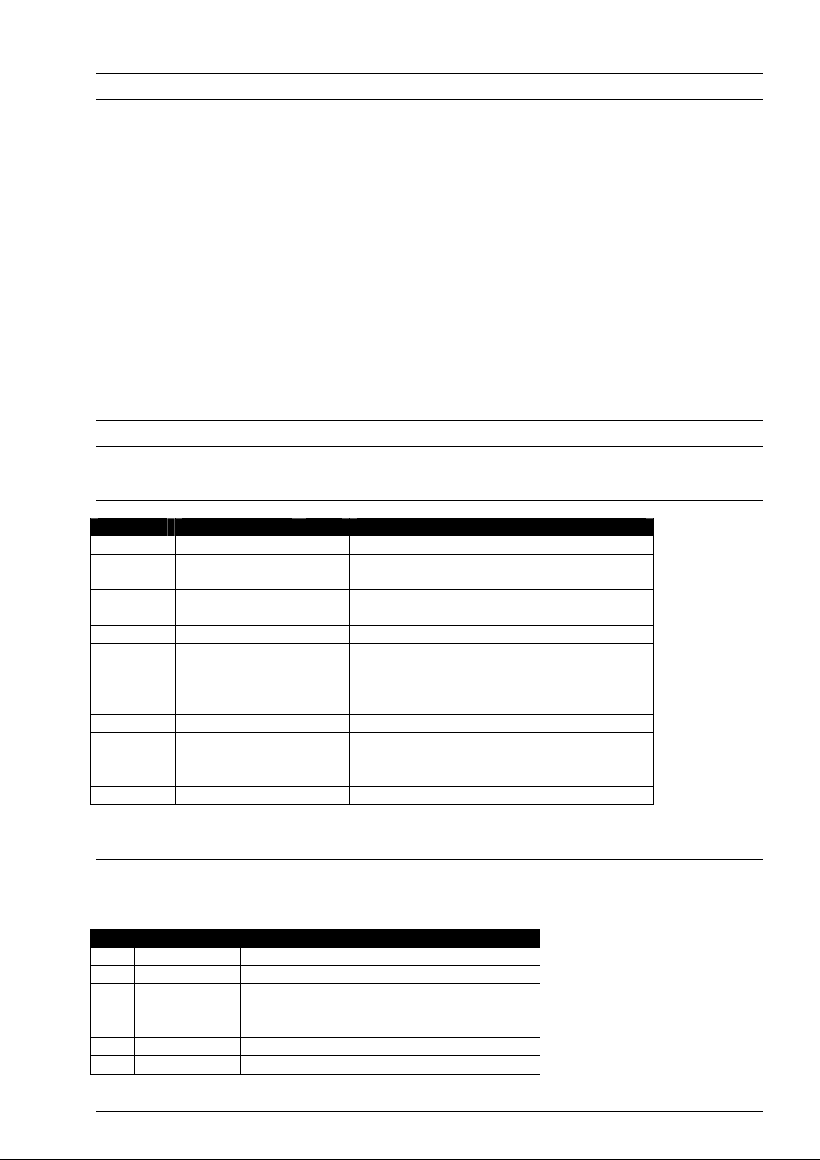
2.1 PANMOD Connector
CON1 Pin
1 CTS IN valid only in RS232 mode
2 RXD
3 TXD
4 RTS OUT valid only in RS232 mode
5 RESET- IN low activ, t
6 BBACTIV
7 WAKEUPHOST OUT HCI : Wake up Host
8 WAKEUPBT
9 VCC IN 3.3V +/- 5%
10 GND - Ground
Signal Type Remark
IN
RS232 mode
USB+
USB+
DCD
GPIO15
GPIO03
USB
OUT
USB
OUT
OUT
I/O
IN
I/O
USB mode
RS232 mode
USB mode
H : Baseband activity (HCI)
DCD with Stollmann SPP
TBD
HCI : Wake up Bluetooth in RS232 mode
TBD
activ
> 5ms
2.2 UART - USB
With HCI software the hardware interface can be configured for USB or RS232 mode. With non
HCI Software only RS232 mode is possible.
Part RS232 mode HCI mode Remark
R2
R5
R7
R13
R14
R15
R16
bold : settings for PANMOD V3
open
open
1K0O
0O
0O
open
open
1k0O USB mode
1k5O USB mode
open RS232 mode
open connect RXD to CON1 Pin 2
open connect TXD to CON1 Pin 3
0O connect USB+ to CON1 Pin 2
0O connect USB- to CON1 Pin 3
18. Nov 2005 2 / 5
Page 3

USERS GUIDE PANMOD for FCC General PANMOD configuration
2.3 HCI WakeUp Bluetooth
When in HCI mode and the deep sleep mode is enabled this signal can be used to wake up the
Bluetooth from deep sleep mode before sending data to the UART interface. To have the ability to
define both initial state R9 and R10 are given.
2.4 HCI Base Band activ / Stollmann-SPP DCD
Part Stollmann SPP
HCI Remark
DCD
R3 open
R11
bold : settings for PANMOD V3
0O
0O
open
GPIO_4 to CON1 Pin 6
GPIO_15 to CON1 Pin 6
2.5 Antenna Type and Matching Network
To select internel or externel antenna use see table below.
Part Int. Antenna Ext. Antenna Remark
C3
C4
C5
ANT1
C6
U.FL
bold : settings for PANMOD V3
0.5pF
10pF
1.5nH
set
open
open
open Pi-Pad : value for Charon
open Pi-Pad : value for Charon
open Pi-Pad : value for Charon
open Internel antenna
2pF U.FL selector
set U.FL connector
2.6 LED’s
LED1 shows when lighting the running state of the ARM7 processor.
LED2 shows in HCI mode the state of the base band activity.
18. Nov 2005 3 / 5
Page 4

USERS GUIDE PANMOD for FCC PANMOD V3 configuration
3 PANMOD V3 configuration
• HCI Software Interface
• RS232 HW Interface with TXD, RXD, RTS, CTS
• HCI Base Band activity om CON1 Pin 6
• Internel antenna with matching network
• No LED`s are populatet
3.1 Picture
Bottom
3.2 Component Placement
Top
Bottom
18. Nov 2005 4 / 5
Top
Page 5

Use only the supplied or approved antenna. Unauthorized antennas, modifications or attachments could
damage the terminal and may contravene local RF emission regulations or invalidate type approval.
4 FCC Compliance
This device complies with Part 15 of the FCC Rules. Operation is subject to the following two
conditions: (1) this device may not cause harmful interference, and (2) this device must accept any
interference received, including interference that may cause undesired operation.
4.1 Labeling Requirements for End Product
The PANMOD is labled with it’s own FCC ID number RFD-PANMOD1.
For the end product which contains the PANMOD V3 there must be a lable containing, at least the
following information :
This device contains FCC ID: RFD-PANMOD1
The label must be affixed on an exterior surface of the end product such that it will be visible upon
inspection in compliance with the modular approval guidelines developed by the FCC.
In addition, the user manual for the end product must contain the following information:
This device complies with Part 15 of the FCC Rules. Operation is subject to the following two
conditions: (1) this device may not cause harmful interference, and (2) this device must accept any
interference received, including interference that may cause undesired operation.
4.2 RF-exposure Statement
The antenna shown in this filing must not be co-located or operated in conjunction with any other
antenna or transmitter. End users may not be provided with the module installation instructions.
OEM integrators and end users must be provided with transmitter operating conditions for
satisfying RF exposure compliance.
For portable applications OEM integrators need no SAR evaluation. The max source-based timeaveraged output of 1.17 mW is below the low threshold of 24mW for d < 2.5 cm.
18. Nov 2005
I:\GPS\Charon\Hardware\Bluetooth\PANMOD\General Doku\USERS GUIDE PANMOD for FCC.doc
5 / 5
 Loading...