

Page 1

WinFrog Device Group: GPS
Device Name/Model: MX9400
Leica Geosystems Inc
23868 Hawthorne Boulevard
Device Manufacturer:
Device Data String(s)
Output to WinFrog:
WinFrog Data String(s)
Output to Device:
WinFrog Data Item(s) and their
RAW record:
DEVICE DESCRIPTION:
There are two different MX 9400 models: the MX9400N and MX9400R. The MX9400N is
designated as a navigator model, whereas the MX9400R is a reference station model.
(Note that the MX9400R can also be used for mobile operations). There is also a MX9401R
model that is the same as the MX9400 except that it is packaged in a weatherproof
housing. All references below will refer to these units simply as the MX9400.
The MX9400 processes both the C/A and P Code measurements to generate threedimensional positions. The MX9400 can accept standard RTCM SC-104 input to
generate and output a differentially corrected position. The MX9400 can also output
pseudorange, ephemeris, and time and date information, which can be used by
WinFrog’s GPS Calculations extension module to internally calculate a GPS position.
The MX9400 utilizes 4 serial interface ports that communicate via a set of proprietary
sentences in accordance with the NMEA –0183 standard to command and control the
equipment. These 4 ports are combined into a 25 pin “DB” type multi-port interface
connector found at the rear of the unit. A special cable must be used in conjunction with
the multi-port interface. This cable splits the single port into 4 separate connectors, each
representing an individual “port” and providing a specific purpose.
Port 1,2, and 3 are RS-232 ports; Port 4 is a RS-422 port. Port 1 is fixed as the Control
Port. All ports are factory set to 9600 baud, but are configurable to range from 300 to
38,400 baud.
The MX9400’s four ports have the following default configurations:
Port 1: RS232, PC control and data messages, 9600 baud default–Input/Output
This port is used to receive control commands from WinFrog.
Port 2: RS232, Instrumentation/Raw data – Output
Torrence, CA 95050 USA
Tel: (310) 7915300
Fax:(310) 791-6108
E-mail: info@leica-gps.com
Configurable: can incl. NMEA and Leica proprietary
A series of $PMVXG type strin gs for unit initialization
and enabling of output options. (See Configuration
Details for more info.)
POSITION 303
TIMEDATE 999
WinFrog User’s Guide - Appendix C – GPS/MX 9400 Page 1 of 22
Page 2

This port is used to output the raw GPS measurement data (ie Pseudorange and
Ephemeris data) to WinFrog
Port 3: RS232, Differential Corrections (MX41R, MX 51R, &MX52R) – Input only for
MX9400N/ Input and Output for MX9400R
Port 4: RS422, Equipment/ NMEA – Input/Output
There are also 2 additional connections found in the MX9400’s rear panel:
• Time: 1PPS - 8.0 to 9.5 VDC; 250 msec pulse; 25 nsec rise time
• Event Input: Closure
NOTE: These default functions can be modified. WinFrog sends the MX9400 a type 71
message to reconfigure the MX9400’ s por t fu nctions. Depending on the user made
selections (described below), the Instrumentation / Raw Data Port (Port 2) and NMEA
(Port4) data output may be reassigned to Port 1.
This allows WinFrog to receive multiple data messages from a single MX9400 port
(Port1), into a single computer port.
DEVICE CONFIGURATION INSTRUCTIONS
WINFROG I/O DEVICES > EDIT I/O:
Serial
Configurable Parameters
The MX9400 is added to WinFrog from the GPS device group. Configure the Device I/O
Parameters dialog box for the appropriate Baud Rate, Data Bits, Stop Bits, Parity, and
Comm Port. These selections refer only to the WinFrog computer port that is connected
to the MX9400 CDU port (i.e. Port 1 on the MX9400, see below for more on the
MX9400’s ports). Select the OK button to confirm the port configuration.
The Configure MX Serial Ports dialog box now appears, as seen below. This dialog box
allows you to configure the MX9400’s 4 serial ports; defining what data will pass through
which port, the Baud rates for the selected ports, and which items are to be sent
through the selected ports.
Make the required selections (as described below), then click the OK button to send this
data to configure the MX9400.
Note that the MX9400’s 4 ports are all combined into a single standard DB25 type
connector found in the back of the MX9400. A special cable is required to “split” the
single port into 4 separate cables that represent the 4 individual ports.
WinFrog User’s Guide - Appendix C – GPS/MX 9400 Page 2 of 22
Page 3
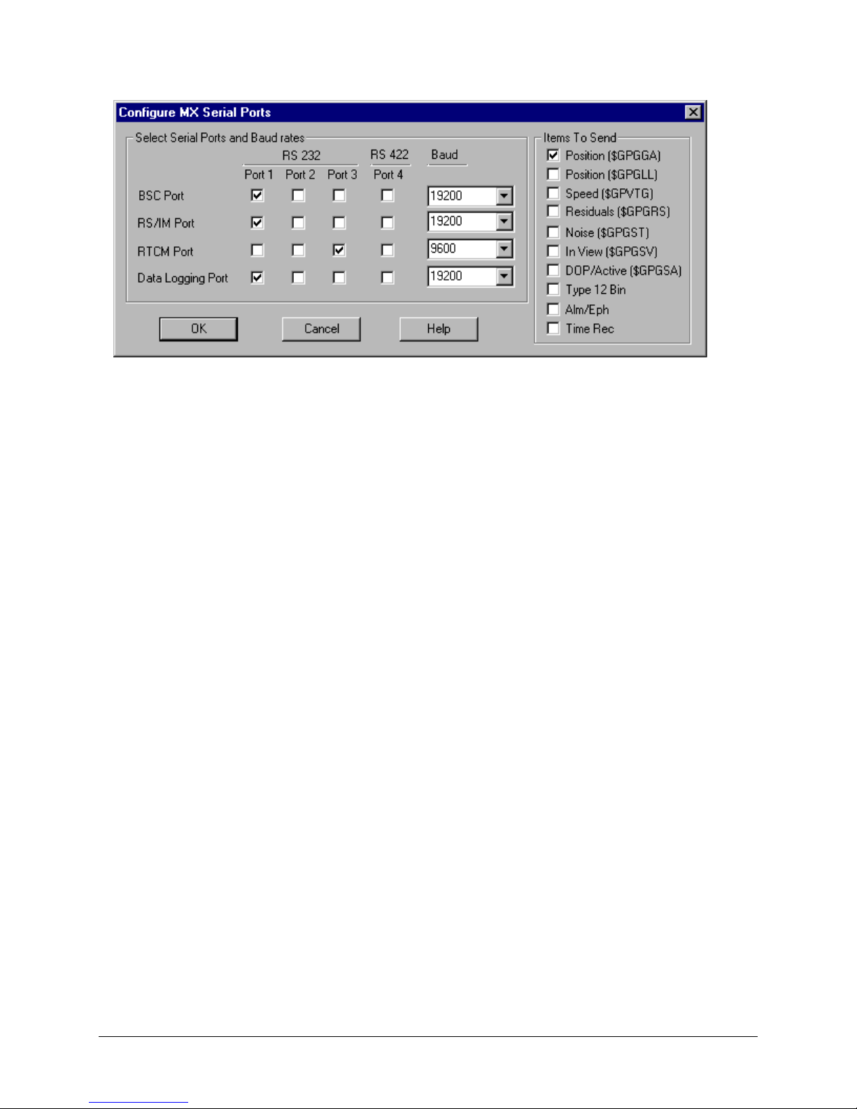
Select Serial Ports and Baud Rates:
As mentioned above, each of the MX9400’s serial ports is designated for specific
tasks. The default configuration of WinFrog’s Configure MX Serial Ports dialog box
(as seen above) reconfigures the MX9400’s ports’ duties so that the MX9400 uses
Port 1 for both input of CDU commands and output of Instrumentation/Raw data and
NMEA messages.
This dialog box also allows you to define which Data Items are to be output by the
MX9400. The Items to Send are defined as follows:
Position ($GPGGA):
This is a standard NMEA format type message (containing GPS Latitude /
Longitude/Status data), output through the “Data Logging “ port.
Position ($GPGLL):
This is a standard NMEA format type message (containing GPS Latitude / Longitude
data) output through the “Data Logging “ port.
Speed ($GPVTG):
This is a standard NMEA format type message (containing Track and Speed Over
Ground data), output through the “Data Logging “ port.
Residuals ($GPGRS):
This is a standard NMEA format type message (containing GPS Residual data),
output through the “Data Logging “ port.
Noise ($GPGST):
This is a standard NMEA format type message (cont aining GPS Pseudorange Error
Statistics), output through the “Data Logging “ port.
InView (GPGSV):
This is a standard NMEA format type message (containing GPS Satellite in view
data), output through the “Data Logging “ port.
DOP/Active(GPGSA):
This is a standard NMEA format type message (containing DOP values and which
satellites are used), output through the “Data Logging “ port.
WinFrog User’s Guide - Appendix C – GPS/MX 9400 Page 3 of 22
Page 4
Type 12 Bin:
This is a Leica proprietary data format conta ining satellite measurement data in a
compressed binary format, output through the Instrumentation / Raw Data port
Alm/Eph:
This refers to the output of GPS Ephemeris and Almanac data in a Leica proprietary
format though the Instrumentation / Raw Data port. The Ephemeris data records
(Leica type 200 proprietary format), are ou tput once an hour for each satellite being
tracked. The Almanac data records (Leica type 100-150 proprietary format), are
output at the request of WinFrog by sending the $PMVXG,074 message).
Time Rec:
This refers to the output of GPS Time recovery data (values computed by the
navigation filter relating to the receiver clock state) through the Instrumentation /
Raw Data port.
If you are using the MX9400 to simply provide a position to WinFrog, you can select
to send only the $GPGGA (preferred) or the $GPGLL item. As defined above, by
default, these NMEA messages are output from the Data Logging port (i.e. port 4). In
order to interface to the MX9400 through just one of its ports, you must reassign this
output to another port - port 1. (Port 1 must be interfaced to WinFrog in order for the
CDU commands to be received, so this is the port of choice). To reassign the output
of NMEA data to Port 1, select the bottom left checkbox.
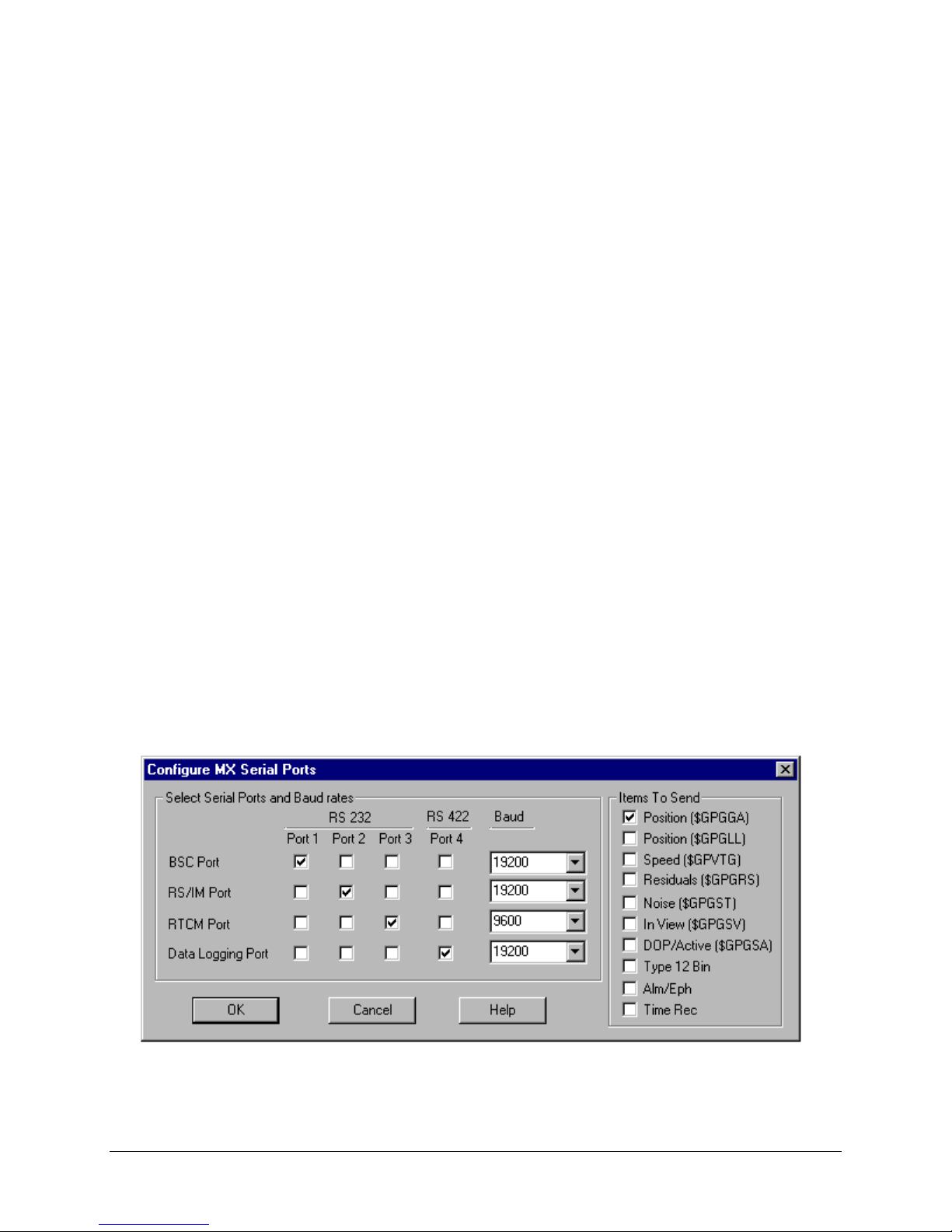
To further clarify the re-assignment of the MX9400 ports, shown below are several
different configurations of the Configure MX Serial Ports dialog box.
The first configuration shown below retains the MX9400’s default port configuration:
i.e. the Control and data messages (referred to as “BSC” in WinFrog) are made
through port 1, the Instrumentation/Raw Data (“RS/IM”) are output through port 2,
Differential RTCM (RTCM) is input/output through port 3, and Equipment/NMEA
(Data Logging) messages are output through port 4. This configuration would require
you to connect all four of the MX9400’s ports to the WinFrog computer.
WinFrog User’s Guide - Appendix C – GPS/MX 9400 Page 4 of 22
Page 5
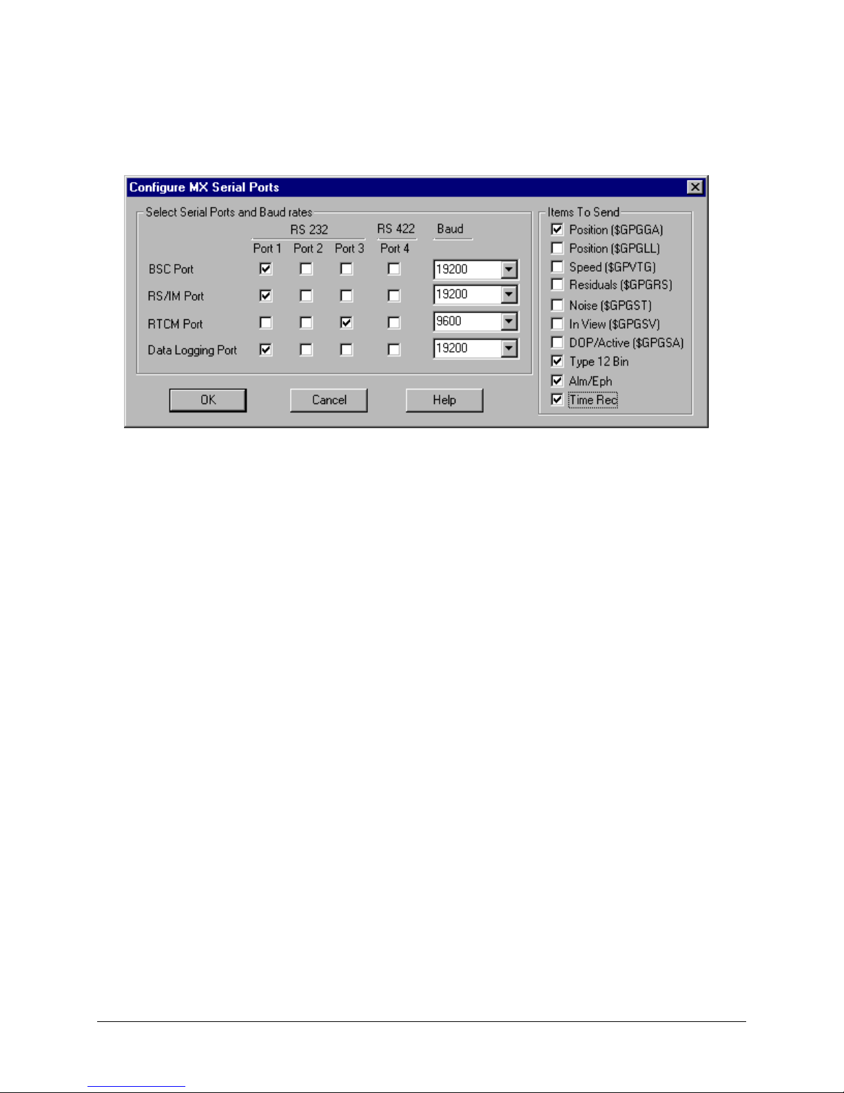
As mentioned previously, in order for WinFrog to communicate with the MX9400
using only one of the MX9400’s four ports, WinFrog reassigns the data output to port
1 of the MX9400, as seen below.
This configuration has assigned PC Control input, Raw data Output, and NMEA
output to port 1. Differential correction data (RTCM) is still assigned to port 3 - this is
to where you would connect the DGPS receiver.
The configuration above has also defin ed the outp ut of NMEA format $GPGGA
positional data, and raw Pseudorange/Ephemeris/Time data required for WinFrog’s
Multi-Ref positioning. This conf iguration is typical of that used in most WinFrog
operations. If you are only using the MX9400’s internally calculated position, you
need only select a Position ($GPGGA or $GPGLL) item.
Once this dialog box is correctly configured, click the OK button. WinFrog sends the
configuration commands to the MX9400, and closes the dialog. To reconfigure any one
of these options, select the MX9400 device in the I/O Devices dialog box, then right
click and select Edit I/O. Click OK to close the standard Edit I/O dialog box, at which
point the Configure MX Serial Ports dialog box appears.
WINFROG I/O DEVICES > CONFIGURE DEVICE:
This device must be configured at the I/O Device window level. In the I/O Devices
window, click the device name to select it, then right-click and select Configure Device.
The MX9400 Configuration dialog box appears, as seen below.
WinFrog User’s Guide - Appendix C – GPS/MX 9400 Page 5 of 22
Page 6
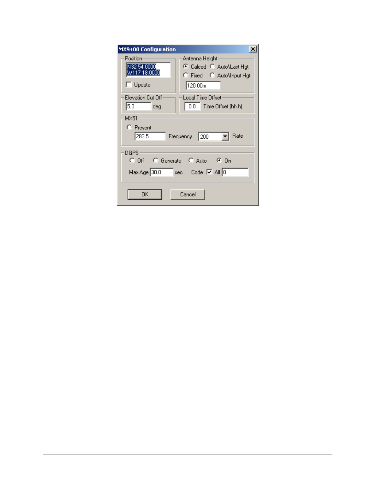
Position:
A valid initial position should be entered. This provides an initial estimate of receiver
position for Rover operations, and reference station coordinates if the MX9400 is
used as a DGPS reference station. You must select the Update Box for the entered
value to be used.
Antenna Height:
Set the MX9400’s Antenna height calculation mode by selecting the appropriate
radio button. Select one of the 4 different modes of height calculation, as desired:
Calculated – This selection forces the MX9400 to use pseudo-range calculations
to compute the GPS antenna’s Height. In this mode, the MX9400 requires a
minimum of four satellites in order to calculate a valid 3-dimension position.
Fixed – This mode selection fixes the MX9400’s h eight to the ellipsoidal height
value entered in the Ellipsoid Height box. In this mode, the MX9400 is able to
calculate valid positions usin g a minimum of three satellites.
Auto\Last Height – The MX9400 will calculate a valid 3D position if four or more
satellites are available. If only three satellites are available, the height is fixed to
that of the last valid calculated height. In this mode, the MX9400 is able to
calculate valid positions usin g a minimum of three satellites.
Auto\Input Height – The MX9400 will calculate a valid 3D position if four or
more satellites are available. If only three satellites are available , the height is
fixed to the value entered in the Ellipsoid Height box. In this mode, WinFrog is
able to calculate valid positions using a minimum of three sate llites.
WinFrog User’s Guide - Appendix C – GPS/MX 9400 Page 6 of 22
Page 7

Note: Ensure that the value entered in the Ellipsoid Height dialog box refers to
the WGS 84 ellipsoid, not Mean Sea Level height.
Elev. Cutoff:
Enter the elevation limit value (in degre es above the horizon). If a satellite drops
below this value, it will not be used in the position calculations.
Local Time Offset:
This value will be added to the observed GPS time to offset WinFrog system time.
MX51:
If the Present radio button is selected, WinFrog will accept RTCM 104 data from the
MX 51R/52R Beacon Receivers. You must also define the Frequency and Rate
settings to match the MX51 settings.
The MX 51R/52R are fully compatible with U.S. Coast Guard and IALA DGPS
beacons and operate with any DGPS beacon broadcasting in the 283.5 to 325.0
KHz band.
DGPS (mode):
The MX9400’s DGPS mode is set within this box. There are four different DGPS
modes: Off, Generate, Auto, and On:
Off – The MX9400 will not use differential corrections in its position computations
for that device even if they are available. Instead it will compute only a single
point GPS solution.
Generate – The MX9400 will generate base station corrections based on the
GPS data being received and the position input at the top of the window.
Auto – The MX9400 will automatically use differential corrections in its GPS
position calculations if those corrections are available to the receiver. If no
corrections are available, the MX9400 will compute a single point solution.
On – Th MX9400 will always attempt to use differential corrections. If no
corrections are available, the MX9400 will not compute a position.
The Maximum Age of Corrections must also be defined. If the age of the received
RTCM corrections exceeds the entered value, the corrections are not applied to the
single point position.
If the All box is checked, then RTCM corrections from any received base station will
be used;
WinFrog User’s Guide - Appendix C – GPS/MX 9400 Page 7 of 22
Page 8

If the All box is not checked, you must define which particular reference station to
use by entering the reference station’s code. The Code entry box allows you to
specify which Differential Base S tation will be used by the MX9400.
Once you have configured this dialog box and clicked the OK butt on, WinFrog sends
the configuration option messages to the MX9400. It may take a few moments for the
changes to take affect in the MX9400.
WINFROG VEHICLE > CONFIGURE VEHICLE DEVICES > DEVICE D ATA ITEM >
EDIT:
Adding the MX9400 device creates four data items: POSITION, PSEUDORANGE,
EPHEMERIS and TIMEDATE.
The MX9400 can provide WinFrog with an internally calculated (DGPS) position
message in one of two NMEA formats; GGA and GLL. This is added to the vehicle by
adding the GPS,MX9400, POSITION data item.
The MX9400 can also output raw Pseudorange and Ephemeris data for WinFrog to
calculate the position itself (using WinFrog’s GPS Calculations extension module).
This is setup by adding both the GPS, MX9400, PSEUDORANGE and the GPS,
MX9400, EPHEMERIS data items to the vehicle’s device list.
Additionally, a Time/Date message can also be output to provide WinFrog with more
precise timing information. Add the GPS, MX9400, TIMEDATE data item.
Typically, both options are desired; the internally configured position provides a backup
position to WinFrog’s more flexible Mu lti-Ref solution.
As per any and all devices, once you’ve added a MX9400 data item to a vehicle’s
Device list, it must be edited to suit the vehicle’s configuration. Note that not all data
items require this vehicle specific configuration.
Data item: GPS, MX9400, POSITION
The POSITION data item must be edited once it is added to a vehicle’s device list.
Highlight the data item in the vehicle’s device list, then select the Edit button. The
Configure Position dialog box appears as seen below.
WinFrog User’s Guide - Appendix C – GPS/MX 9400 Page 8 of 22
Page 9

Calculation:
Set the Calculation selection to Primary or Secondary. Devices set to Primary
calculation are used to provide a vessel position. Note that more than one Primary
positioning device can be added to a vehicle’s device list; data from these devices
will be combined in a weighted mean solution. (See the paragraph on Accuracy
below for more on the weighting of Primary calculation device data).
If the Calculation type is set to Secondary, WinFrog will simply monitor the device’s
data. WinFrog will not use the position data from the device in the final solution of
the vehicles’ position.
Note: In the case of Primary device failure, WinFrog will not automatically use the
Secondary devices for the vessel’s position computation. Instead, the vehicle’s
positioning will go to dead reckoning (if dead reckoning is turned on). You must
manually change a Secondary device to Primary in order for the data to be utilized.
Use For Heading Calculations:
Select this checkbox if the device is to be used in conjunction with another GPS
device for determination of the heading of the vessel.
Graphics:
If On is selected, a labeled square will show the raw (offset but unfiltered) location of
the GPS antenna in the Graphics and Bird’s Eye windows. This provides a means of
comparing raw device and filtered vehicle positions.
Elevation:
Setting the Elevation option to On will result in the elevation determined by GPS to
be used as the elevation of the vessel referencing the GPS (WGS84) Ellipsoid. The
sounder data recorded in WinFrog’s .RAW data files will not be affected.
This option is meant only for those applications where there is no fixed vertical
reference (i.e. mean sea level), such as on a river. For acceptable results, this option
requires the use of high accuracy “RTK” GPS data.
WinFrog User’s Guide - Appendix C – GPS/MX 9400 Page 9 of 22
Page 10

Accuracy:
The Accuracy value entered provides WinFrog with the expected accuracy of the
position from this device. This value is used in the weighting of this device compared
to other positioning devices that may be added to the vehicle’s device list. The
smaller the value entered, the more accurate it is considered to be, and hence the
more weight that will be applied to the device’s data.
The Accuracy parameter can be changed from the suggested values; changes
should be made with caution, however, as they will affect the final filtered position of
the vehicle.
Code:
This entry window is used when the GPS data is being received by a remote GPS
receiver connected via telemetry link. If this is the case, set the Code to coincide
with the code parameters associated with the GPS unit being used.
For all other applications, the Code entry must be set to 0.
Offsets:
Offsets are required to associate the GPS antenna position with the vessel’s
Common Reference Point (i.e. CRP). The offsets are applied from CRP (of the
vehicle) to the GPS antenna location.
Forward Offsets are entered as positive values.
Aft Offsets are entered as negative values.
Starboard Offsets are entered as positive values.
Port Offsets are entered as negative values.
Height Offsets are positive upwards. (It is suggested that the vessel’s Height origin
should be at the water line.
Data item: GPS, MX9400, PSEUDORANGE
As mentioned above, both the Pseudorange device and the Ephemeris device must be
added to the vehicle’s device list. You must edit the Pseudorange device to suit the
vehicle. There is no configuration required for the Ephemeris device.
In the vehicle’s Devices list, highlight the GPS, MX9400, PSEUDORANGE device and
select the Edit button. The Pseudorange Calculation dialog box appears, as seen
below.
WinFrog User’s Guide - Appendix C – GPS/MX 9400 Page 10 of 22
Page 11

Calculation:
Select either the Primary or Secondary radio button. Devices set to Primary
calculation are used to produce a vehicle position. If more than one positioning
device added to the vehicle’s device list is deemed as primary, WinFrog will weight
them based on the accuracy value entered. Devices with a higher accuracy values
(i.e. lower entered value) will be weighted higher.
If a positioning device’s calculation is set to Secondary, WinFrog will not use the
position data in the calculation of the vehicles’ position solution; that device’s
position will simply be received and monitored. Note that in the case of Primary
device failure, WinFrog will not automatically use the Secondary devices for the
vehicle position computation. Instead, it will start dead re ckon ing (if dead reckoning
is turned on). You must manually change a secondary device to primary status if you
want to utilize the data coming from that device.
Use Elevation:
Setting the Elevation option to “On” will result in the elevation determin ed by GPS to
be used as the elevation of the vessel’s CRP referencing the GPS (WGS84)
Ellipsoid. The height of the antenna above (below) the CRP must be entered. Do not
enable this option unless you are utilizing high accuracy (centimeter level) RTK type
GPS positioning.
WinFrog User’s Guide - Appendix C – GPS/MX 9400 Page 11 of 22
Page 12

Accuracy:
The Accuracy value entered provides WinFrog with the expected accuracy of the
position from this device. This value is used in the weighting of this device compared
to other positioning devices that may be added to the vehicle’s device list. The
smaller the value entered, the more accurate it is considered to be, and hence the
more weight that will be applied to the device’s data. The Ac curacy pa rameter can
be changed from the suggested values, although changes should be made with
caution, as they will affect the final filtered position of the vehicle.
The Velocity value is used in positional filtering. The lower the value entered, the
more smoothing that is applied.
Remote Unit ID:
The Remote Station ID parameter is set to zero (0) unless the GPS device is
interfaced to WinFrog via a telemetry device.
Antenna Height:
Set the Antenna Height using the radio buttons and the (input) Ellipsoid Height field.
Settings are as follows:
Calculated – Select this option to force WinFrog to calculate the GPS antenna
Height as well as its Latitude and Longitude. In this mode, WinFrog requires a
minimum of four satellites to be visible.
Fixed – Select this option to fix the GPS antenna ellipsoid height to the value
entered in the Ellipsoid Height field. In this mode, WinFrog is able to calculate
valid positions using a minimum of three satellites.
Auto\Last Height – If this mode is selected, WinFrog will calculate a 3D position
if four or more satellites are available. If only three satellites are visible, or if the
VDOP of the solution exceeds the value set in the Alarms dialog box, the height
is fixed to that of the last valid position. In this mode WinFrog is able to calculate
valid positions using a minimum of three satellites.
Auto\Input Height – If this mode is se lected, WinFrog will calculate a valid 3D
position if four or more satellites are available. If only three satellites are
available, or if the VDOP of the solution exceeds the value set in the Alarms
dialog box, the height is fixed to the value entered in the Ellipsoid Height field.
In this mode, WinFrog is able to calculate valid positions using a minimum of
three satellites.
Note: The Antenna height entered in the Pseudorange Calculation dialog box
refers to the WGS 84 Ellipsoid.
Offsets:
Offsets are entered to relate the GPS antenna position to the vessel’s Common
Reference Point (CRP). Offsets are entered as measured from the CRP (of the
WinFrog User’s Guide - Appendix C – GPS/MX 9400 Page 12 of 22
Page 13

vehicle) to the device (antenna) location. Offsets Fore and Starboard are entered as
positive values, offsets measured Port and Aft are entered as negative values. Rule
of thumb suggests the CRP “Z” reference should be at the water line.
DGPS Mode:
Select the desired mode of DGPS operation
There are four different DGPS modes: Auto, On, Off and Generate.
Auto: WinFrog will automatically use differential corre ctions in its position
calculations, when available. If no corrections are available, WinFrog will
compute a single point (aka autonomous) position solution.
On: WinFrog will always attempt to use differential corre ctions. If no corrections
are available, no position will be computed.
Off: WinFrog will not use differen tial corrections in its position computations,
even if they are available. Instead it will always compute a single point GPS
solution.
Generate: WinFrog will generate differential corrections based on a fixed
reference position. This option is used for Base Stations only.
Phase Smoothing:
Phase smoothing utilizes the GPS rece iver’s observations of the GPS satellite’s
carrier signals. Because the GPS L1 frequency has a wavelength of only 19 cm.,
measurements made using this signal will provide higher accuracy than
measurements made on the C/A code message modulated onto the L1 signal. Note,
however, that since the carrier phase position is derived from the C/A code position,
it does not offer an improvement in precision.
If the Phase Smoothing feature is enabled, WinFrog will use the C/A Code derived
(DGPS corrected) position to derive the number of L1 wavelengths to each of the
observed satellites. Over the length of time entered into the Filter Length field
(value in seconds), WinFrog will switch the GPS calculated position from the C/A
code position to the derived Carrier Phase position.
WinFrog will continue to use the carrier phase data to provide positioning until the
Cycle Slip Tolerance is exceeded. A Cycle Slip is the loss of lock on a satellite’s
signal. This loss of lock forces WinFrog to re-establish the number of wavelengths
from the antenna to the satellite. If the numbe r of cycle slips exceeds the Cycle Slip
Tolerance, WinFrog will resort back to the C/A code position and re-calculate the
number of wavelengths to all received satellites.
WinFrog User’s Guide - Appendix C – GPS/MX 9400 Page 13 of 22
Page 14

Graphics:
Select the On radio button to display a labeled square in the Graphics and Bird’s
Eye displays, depicting the raw (unfiltered) location of the GPS antenna. This
provides a means of comparing raw and filtered positions between different sources.
Display:
The selection made here determines which type of information will be displayed in
WinFrog’s Calculations window (when the GPS Pseudorange device is turned on for
display in that window). Select from the three provided options:
Results – The Calculations window will show the results of the GPS
Calculations, including the Multi-Ref position and all individual solutions.
Data - The Calculations window will show the results of the GPS Calculations,
including the Multi-Ref position and data related to each individual carrier phase
solution (when Phase Smoothing is enabled).
Statistics - The Calculations window will show the results of the GPS
Calculations, including the Multi-Ref position and statistical data related to each
individual solution.
Use For Heading Calculations:
Select this checkbox if the device is to be used in conjunction with another GPS
device for determination of heading of the vessel. In most cases, only high accuracy
receivers should be used for heading calculations as WinFrog simply inverses the
individual sensors’ raw positions to derive the bearing between them.
Alarms:
Click this button to view and enable various GPS alarms, as described below.
WinFrog User’s Guide - Appendix C – GPS/MX 9400 Page 14 of 22
Page 15

GDOP – Geometric Dilution of Precision. GDOP is a numerical value that se rves a s
a measure of the effect of the satellite constellation’s geometry on the derived
positional accuracy. In other words, the GPS receiver’s measurement accuracy is
multiplied by the GDOP value to derive the overall positional accuracy of the GPS
receiver (including the three positional dimensions and clock offset). If the GDOP
mask is set to On and the calculated GDOP exceeds the entered value, WinFrog will
not compute a position solution using pseudoranges. If the Calculations window is
enabled, an alarm will sound to indicate that the GDOP has been exceeded.
VDOP – Vertical Dilution of Precision. This paramete r is also calculated from satellite
geometry and gives an indication of the expected accuracy of the vertical component
of the GPS position solution. If the VDOP mask is set to On and the calculated
VDOP exceeds the entered value, WinFrog will automatically initiate 2D or fixed
height mode using either the last valid calculated height or the height entered in the
Antenna Height Ellipsoid Height field. If the Calculations window is enabled, an
alarm will sound to indicate that the VDOP has been exceeded.
Elev. Cutoff – (Elevation Angle Cutoff). WinFrog will not use measurements from
any satellites with elevation angles below the angular value input in the Elevation
Angle Cutoff field. Any satellites not used in the pseudo range position calculations
are indicated in the Calculations window by a change of color.
Min SN – Minimum Signal to Noise. This field is used to set the minimum signal to
noise ratio for the pseudorange calculation s. If a satellite’s signal to noise ratio falls
below the entered value, the satellite will not be used in p osition computation by
WinFrog. Satellites not used in the position computation due to low signal to noise
values are indicated in the Calculations window by a change of color.
Max Res – Maximum Measurement Residual. WinFrog will not use any satellite
measurement with a residual greater than the Maximum Measurement Residual in
its pseudorange position computations. Satellites not used in the position
computation due to measurement residuals are indicated in the Calculations window
by a change of color.
Max RTCM Age – Maximum RTCM Differential Correctio n Age. This parameter sets
the maximum latency of real time differential corrections for pseudoranges. If the
maximum latency is exceeded, WinFrog will not apply the correctio ns from that
RTCM source. To indicate this condition, the STAT light in the Position portion of the
Calculations window will turn yellow. Click on the ACK button to acknowledge this
alarm.
Test:
Click this button to open the GPS Solution Statistical Testing dialog box, as seen
below.
WinFrog User’s Guide - Appendix C – GPS/MX 9400 Page 15 of 22
Page 16

This dialog box provides you with the ability to enable o r disable statistical w test and F
tests. By default, both of the w-test and the F-test are turned off.
w-Test:
The w-test entails normalizing the residuals of a GPS pseudorange solution and
testing these against a 99% conf iden ce limit for outlie rs. This lim it is 2. 576. If outliers
are found, they are removed and the solution is re-executed excluding that satellite
data pertaining to the outlier. If more than one satellite is found to produce a residual
outlier, only that satellite with the largest normalized residual is eliminated. This
continues until no outliers are present or until the exclusion of any more data would
result in insufficient data for a solution (fo ur satellites fo r 3D and three fo r 2D). Since
the normalized residuals tend towards being equal with reduced redundancy (as the
number of satellites used in the solution approaches the minimum required), it is
unlikely that WinFrog will ever have to stop the exclusion of data due to insufficient
satellites. Nonetheless, WinFrog still checks for this condition.
Caution should be exercised when using this option. If the vessel is too far away
from the selected reference statio ns and/or there are few satellites in common with
the vessel and the reference station(s) the w-test option may eliminate data to the
point where the solution approaches the minimum required.
F-Test:
The F-test is a check of the unit variance of the GPS pseudorange solution. This
confirms the validity of the model used for the solution and the weighting of the
observations used. Note that it is only a confirmation check, no data or solution
results are thrown out based on the results of the test.
The unit variance is the sum of the weighted, squared residuals, divided by the
degrees of freedom (number of redundant measurements) in the solution. The FTest should result in unity. If the unit variance is consistently different from unity, it
indicates that there may be a problem with the stochastic model used, or an
unmodeled bias in the data.
WinFrog User’s Guide - Appendix C – GPS/MX 9400 Page 16 of 22
Page 17

Ref-Stns:
Click the RefStns button in the Pseudorange Calculation dialog box to open the Select
DGPS Reference Stations dialog box, as seen below.
The Select DGPS Reference Stations dialog box allows you to define which reference
stations will be used by WinFrog in its Multi-Ref solution. You can either configure
WinFrog to simply use all received stations (to a maximum of 5), or you can control the
use of corrections, as deemed proper.
To use all received DGPS corrections, select the Use all Available Stations checkbox.
When this checkbox is selected, all available RTCM corrections are utilized in the
solution, each with the same Relative Standard Deviation.
The individual station method is preferable as it allows you to remove or de-weight
solutions that may not agree with the weighted mean solution. If this method is used,
you should add the RTCM data item to the vehicle’s device list once for each solution,
then edit that solution entering the proper code and coordinates. For example, if there
are 5 Reference stations to be used in the Multi-Ref solution, add the RTCM,RTCM1,
DGPS-COR’s data item to the vehicle’s device list 5 times.
From the Configure Vehicle-devices dialog box, highlight and edit each RTCM data item
to indicate a unique Code.
Now, back in the Select DGPS Reference Station dialog box, ensure that the Use all
Available Stations checkbox is not selected. Now the individual reference station ID’s
WinFrog User’s Guide - Appendix C – GPS/MX 9400 Page 17 of 22
Page 18

must be entered, along with station usage and relative standard deviation values, as
detailed below:
Select DGPS Reference Stations:
Selection of individual stations is as follows:
ID – The Reference Station identification code. See SkyFix documentation for a
listing of all SkyFix reference station ID Codes. Coast Guard Beacon corrections
also contain unique codes for each station.
In the above example, SkyFix stations 535, 545 and 570 are used with assigned
relative standard deviations along with Coast Guard station 336. Coast Guard
Station 334 is monitored and is therefore not utilized in the position solution.
Off – Corrections from the selected Reference Station will not be used in the
Multi-Ref position solution. This individual solution and will appear in red text in
WinFrog’s Calculations window and not update.
Use – Reference Station is used in the Multi-Ref pos ition solution, and will
appear in the Calculations window in black text. This individual solution will
appear in red text if no solution (refer to DGPS Mode) can be calculated from the
data.
Monitor – Reference Station is simply monitored by WinFrog, and is not used in
the Multi-Ref position. This solution will appear in yellow text in WinFrog’s
Calculations window.
Rel. Std. Dev – This value defines the relative standard deviation of this solution
as compared to the other solutions used in the Multi-Ref position. Equal Rel. Std.
Dev. values indicate that all individual solutions will be equally weighted in the
Multi-Ref solution. Entering a highe r Re l. Std. Dev value will de-weight an
individual solution compared to the others in the Multi-Ref solution.
CONFIGURE CALCULATIONS WINDOW
A Calculations window can be configured in WinFrog, allowing you to monitor the status
of the Mulit-Ref solution and make appropriate adjustments. To open the Calculations
window select View > Calculations from the main menu. In the Calculations window,
select the appropriate vehicle from the dropdown list and click the Setup button.
In the Setup Calculation View dialog box, select the Position and Data Item Text
checkboxes. Next, highlight the Pseudorange data item, click the On button and exit
with OK. Refer to Chapter 14, GPS Calculations Displays section of the WinFrog User’s
Guide for more detailed descriptions of the various options and displays available with
the Calculations window.
WinFrog User’s Guide - Appendix C – GPS/MX 9400 Page 18 of 22
Page 19

Data item: GPS, MX9400, TIMEDATE
The TIMEDATE data item must be edited once it is added to a vehicle’s device list.
Highlight the data item in the vehicle’s device list, then select the Edit button. The Time
Synchronization dialog box appears as seen below.
Synchronize Mode
The synchronization can be turned On or Off. Note that multiple TIMEDATE data
items can be added to the same or other vehicles, but WinFrog will only allow one to
be set to On and actually be used to synchronize the WinFrog clock. The others can
only be compared to the WinFrog clock.
Synchronization Settings
The tolerance setting controls the maximum limit of the deviation of the WinFrog
clock from the timing device before WinFrog resets its clock. This should not be set
too small, or the clock will constantly be re-setting. A tolerance of 50 ms for a 1PPS
pulse results in the resetting of the clock approximately every 5-6 minutes.
WinFrog monitors the variation between the UTC time and the WinFrog clock using
a fading history of the last 20 samples of the variation between the WinFrog clock
synchronization time stamp and the associated UTC time. This is filtered using a
Central Tendency algorithm. When the filter result exceeds the tolerance, the clock
is reset.
Local time offsets can be entered to allow synchronization to UTC while working in a
local time zone. The offset is entered in +/-hours.
Raw Data Logging Control
You can control the logging of the TIMEDATE raw data records. Every time
synchronization data reception update can be logged, i.e. a raw record every
second. Alternatively, the data is only logged to the raw file when the clock is reset.
WinFrog User’s Guide - Appendix C – GPS/MX 9400 Page 19 of 22
Page 20

The data logged includes the time of the clock adjustment and the amount it was
adjusted.
Note that this is only in affect if Raw Data recording is turned on.
Monitoring the synchronization
The synchronization of the WinFrog clock can be monitored from the Calculation
Window using the Data Item Text and Time Series options.
In the Data Item Text panel, the following information is displayed:
• Status
Displays the data type status (On/Off) and the associated device status.
• Sync’d at
Displays the time the WinFrog clock was last adjusted.
• Computer time
WinFrog clock time stamp of last synchronization data input
• UTC time
UTC time (from device) of last synchronization data input
• Raw Delta
The difference between the UTC and associated WinFrog time stamp (UTC –
WinFrog) for the last epoch
• Filter Delta
The difference between the UTC and filtered WinFrog time for the last epoch
In the Time Series panel, the difference between the UTC time and the raw and filtered
WinFrog times are plotted.
WinFrog User’s Guide - Appendix C – GPS/MX 9400 Page 20 of 22
Page 21

CONFIGURATION DETAILS:
Refer to the MX9400 operator’s manual and CDU programming documentation for
information on setting up the receiver to output a NMEA GGA positioning string.
RAW DATA LOGGING:
WinFrog sends various $PMVXG messages to the MX9400,depending on operator
option selections:
• $PMVXG,035,0,,,"); // set receiver mode to “navigator”
• $PMVXG,007,,1,,,,,,"); // stop proprietary outputs on CDU port
• $PMVXG,026,,1,,,,"); // turn off equip port output
• $PMVXG,007,412,,1,,5,,,"); // turn psn output to CDU port
• $PMVXG,007,100,,1,,2,,,"); // turn SV trking status output to CDU port
• $PMVXG,007,000,,1,,5,,,"); // turn RCVR status output to CDU port
• $PMVXG,001,%d,,%.3lf,%.3lf,,,%.1lf,%c,%.0lf", tempHgtMode,
• $PMVXG,053,%d,%.0lf,0,,6,%d,0,0,0,", tempDgpsCode
• $PMVXG,034,%d,0,0,%.1lf,%d,0,,,", tempBitR. Rate of 50 (1), 100 (2) or 200 (3).
Items to Send Messages:
$PMVXG,026,XXX,,1,1 .0,6,"); // turn on GP XXX message, where XXX can b e:
• GGA
• GLL
• VTG
• GSA
• GST
• GRS
• GSV
• Type 12 Bin
• Almanac / Ephemeris
• Time Record
Note: Refer to NMEA0183 Sentence formats for the above data sentences.
WinFrog User’s Guide - Appendix C – GPS/MX 9400 Page 21 of 22
Page 22

MX9400 SPECIFICATIONS (Manufacturer’s):
Receiver Description
• Tracking: 12-channel continuous tracking of code and phase.
• Sensitivity: -143dBm Costas threshold
• Measurement Accuracy: 10cm code (single epoch) 5mm phase
Connectors
• Multiport I/F: DB25S
• Time: SMB (Jack receptacle)
• Event Input: SMB (Jack receptacle)
• Antenna: SMA (Jack receptacle)
• Power: DC Power Jack (0.1 dia.)
Navigation Mode
• Operating Modes: 2D or 3D ,DGPS, GPS or auto selection
• DGPS Input: RTCM SC-104 format
• Time to First Fix: 1 minute typical
• Accuracy: Position: 30 cm RMS/15 cm RMS (AccucodeTM)
• Velocity: .05 m/s RMS
• Dynamics: 3g
WinFrog User’s Guide - Appendix C – GPS/MX 9400 Page 22 of 22
 Loading...