

Page 1

Leica iCON gps 80
User Manual
Version 2.7
English
Page 2

Introduction
Purchase Congratulations on the purchase of a Leica iCON gps 80 system.
This manual contains important safety directions as well as instructions for setting up
the product and operating it. Refer to "1 Safety Directions" for further information.
Read carefully through the User Manual before you switch on the product.
Product Identification
Trademarks • Bluetooth® is a registered trademark of Bluetooth SIG, Inc.
Validity of this
manual
Available documentation
The model and serial number of your product are indicated on the type plate.
Always refer to this information when you need to contact your agency or Leica
Geosystems authorised service workshop.
All other trademarks are the property of their respective owners.
This manual applies to the Leica iCON gps 80 instrument and the Leica CGA60 antenna.
Name Description/Format
Leica iCON gps
80 Quick Guide
Leica iCON gps
80 User Manual
Refer to the following resources for all Leica iCON gps 80 documentation/software:
• the Leica USB documentation card.
• https://myworld.leica-geosystems.com
Provides an overview of the product together with technical data and safety directions. Intended as a quick
reference field guide.
All instructions required in order to operate the product
to a basic level are contained in the User Manual.
Provides an overview of the product together with technical data and safety directions.
99
9
myWorld@Leica Geosystems (https://myworld.leica-geosystems.com) offers a
wide range of services, information and training material.
With direct access to myWorld, you are able to access all relevant services whenever
it is convenient for you, 24 hours a day, 7 days per week. This increases your efficiency
and keeps you and your equipment instantly updated with the latest information from
Leica Geosystems.
Service Description
myProducts Add all products that you and your company own and explore your
world of Leica Geosystems: View detailed information on your products and update your products with the latest software and keep upto-date with the latest documentation.
myService View the current service status and full service history of your prod-
ucts in Leica Geosystems service centres. Access detailed information on the services performed and download your latest calibration
certificates and service reports.
mySupport View the current service status and full service history of your prod-
ucts in Leica Geosystems service centres. Access detailed information on the services performed and download your latest calibration
certificates and service reports.
iCON gps 80, Introduction
2
Page 3

Service Description
myTraining Enhance your product knowledge with Leica Geosystems Campus -
Information, Knowledge, Training. Study the latest online training
material on your products and register for seminars or courses in
your country.
myTrustedServices
Add your subscriptions and manage users for Leica Geosystems
Trusted Services, the secure software services, that assist you to
optimise your workflow and increase your efficiency.
iCON gps 80, Introduction
3
Page 4

Table of Contents
In this manual Chapter Page
1 Safety Directions
1.1 General Introduction 7
1.2 Definition of Use 7
1.3 Limits of Use 8
1.4 Responsibilities 8
1.5 Hazards of Use 9
1.6 Electromagnetic Compatibility EMC 12
1.7 FCC Statement, Applicable in U.S. 13
2 Description of the System
2.1 System Components 15
2.1.1 General Information 15
2.1.2 Power Concept 17
2.2 Unpacking the Container 18
2.2.1 iCON gps 80 Dual GNSS Container 18
2.2.2 iCON gps 80 Base Station Container 19
2.3 Instrument Components 20
3 Using iCON gps 80
3.1 Power Supply 23
3.2 Installing a SIM Card 23
3.3 Slot-in-Device 24
3.4 External Radios 25
3.5 Using USB Memory Devices 27
3.6 Quick Release Machine Bracket CMB6 28
3.7 Installation on a Machine 29
3.8 Antenna Heights 33
3.8.1 Understanding Antenna Heights 33
3.8.2 The Mechanical Reference Plane, MRP 34
3.8.3 Measuring the Antenna Height for a Pillar Setup 34
3.8.4 Measuring the Antenna Height for a Tripod Setup 35
3.8.5 Measuring the Antenna Height for a Mast Setup 36
3.9 Dual GNSS Positioning and Heading 36
7
15
23
4 Setups with Accessories
4.1 Single GNSS Setup, with Internal Radio 38
4.2 Single GNSS Setup, with External Radio 39
4.3 Dual GNSS Setup, with Internal Radio 40
4.4 Local Base Station Setup, on Tripod 41
4.5 Local Base Station Setup, on Pillar 42
4.6 Local Base Station Setup, with External Radio 43
4.7 Local Base Station Setup, Permanent 44
5 iCON gps 80 User Interface
5.1 User Interface Description 46
5.2 Main Menu 47
5.3 Submenus 50
5.4 iCON gps 80 Screen in Machine Control Mode 60
iCON gps 80, Table of Contents
38
46
5.3.1 Navigation in Submenus 50
5.3.2 How to Change Settings and Edit Values 51
5.3.3 Available Sub Menus 53
4
Page 5

6 Software Tools
6.1 Base Setup 62
6.1.1 Base Setup Description 62
6.1.2 Manual Base Setup 62
6.1.3 Base Setup using BasePilot 76
6.2 Rover Setup 77
6.3 ORP and NMEA Output 85
6.4 Raw Data Logging 87
6.5 iCON Telematics 87
6.6 Import, Export, or Delete Data 91
6.7 Licensing 93
62
7 Coordinate Systems
8 Care and Transport
8.1 Transport 95
8.2 Storage 95
8.3 Cleaning and Drying 95
9 Technical Data
9.1 Technical Data iCON gps 80 96
9.1.1 Tracking Characteristics 96
9.1.2 Accuracy 96
9.1.3 General Technical Data of the Instrument 97
9.2 Antennas Technical Data 100
9.3 Pin Assignments and Sockets 101
9.4 Conformity Declarations 103
9.4.1 iCON gps 80 103
9.4.2 GFU14, SATEL Satelline 3AS, GFU27, SATEL Satelline
M3-TR1 105
9.4.3 GFU15, Pacific Crest PDL 106
9.4.4 Intuicom 1200DL 107
9.4.5 TFR-300L 108
9.4.6 CCD14 - SATEL TA13 109
9.4.7 CCD15 - Intuicom 900SLR 110
94
95
96
10 Software Licence Agreement
Appendix A NMEA Message Formats
A.1 Overview 113
A.2 Symbols Used for Describing the NMEA Formats 113
A.3 GGA - Global Positioning System Fix Data 115
A.4 GGK - Real-Time Position with DOP 116
A.5 GGQ - Real-Time Position with CQ 117
A.6 GLL - Geographic Position Latitude/Longitude 118
A.7 GNS - GNSS Fix Data 118
A.8 GSA - GNSS DOP and Active Satellites 119
A.9 GSV - GNSS Satellites in View 120
A.10 HDT - Heading, True 121
A.11 LLK - Leica Local Position and GDOP 121
A.12 LLQ - Leica Local Position and Quality 122
A.13 RMC - Recommended Minimum Specific GNSS Data 123
A.14 VTG - Course Over Ground and Ground Speed 123
A.15 XDR – Transducer Measurements 124
A.16 ZDA - Time and Date 124
iCON gps 80, Table of Contents
112
113
5
Page 6

Appendix B ORP – Orientation and Position
126
Appendix C Glossary
C.1 C 129
C.2 G 130
C.3 N 131
C.4 W 133
129
iCON gps 80, Table of Contents
6
Page 7

1 Safety Directions
1.1 General Introduction
Description The following directions enable the person responsible for the product, and the
person who actually uses the equipment, to anticipate and avoid operational hazards.
The person responsible for the product must ensure that all users understand these
directions and adhere to them.
About Warning
Messages
Warning messages are an essential part of the safety concept of the instrument. They
appear wherever hazards or hazardous situations can occur.
Warning messages...
• make the user alert about direct and indirect hazards concerning the use of the
product.
• contain general rules of behaviour.
For the users‘ safety, all safety instructions and safety messages shall be strictly
observed and followed! Therefore, the manual must always be available to all persons
performing any tasks described here.
DANGER, WARNING, CAUTION and NOTICE are standardised signal words for identifying levels of hazards and risks related to personal injury and property damage. For
your safety, it is important to read and fully understand the following table with the
different signal words and their definitions! Supplementary safety information
symbols may be placed within a warning message as well as supplementary text.
Type Description
DANGER
WARNING
Indicates an imminently hazardous situation which, if not
avoided, will result in death or serious injury.
Indicates a potentially hazardous situation or an unintended
use which, if not avoided, could result in death or serious injury.
CAUTION
NOTICE
)
iCON gps 80, Safety Directions
Indicates a potentially hazardous situation or an unintended
use which, if not avoided, may result in minor or moderate
injury.
Indicates a potentially hazardous situation or an unintended
use which, if not avoided, may result in appreciable material,
financial and environmental damage.
Important paragraphs which must be adhered to in practice as
they enable the product to be used in a technically correct and
efficient manner.
7
Page 8

1.2 Definition of Use
Intended use • Computing with software.
• Carrying out measurement tasks using various GNSS measuring techniques.
• Recording GNSS and point related data.
• Remote control of product.
• Data communication with external appliances.
• Measuring raw data and computing coordinates using carrier phase and code signal
from GNSS satellites.
Reasonably foreseeable misuse
WARNING
• Use of the product without instruction.
• Use outside of the intended use and limits.
• Disabling safety systems.
• Removal of hazard notices.
• Opening the product using tools, for example screwdriver, unless this is permitted
for certain functions.
• Modification or conversion of the product.
• Use after misappropriation.
• Use of products with obvious damages or defects.
• Use with accessories from other manufacturers without the prior explicit approval
of Leica Geosystems.
• Inadequate safeguards at the working site.
• Controlling of machines, moving objects or similar monitoring application without
additional control and safety installations.
Unauthorised modification of building and constructions machines by mounting or
installing the product may alter the function and safety of the machine.
Precautions:
Follow the instructions of the machine manufacturer. If no appropriate instruction is
available, ask machine manufacturer for instructions before mounting or installing the
product.
1.3 Limits of Use
Environment Suitable for use in an atmosphere appropriate for permanent human habitation: not
suitable for use in aggressive or explosive environments.
DANGER
Local safety authorities and safety experts must be contacted before working in
hazardous areas, or close to electrical installations or similar situations by the person
in charge of the product.
1.4 Responsibilities
Manufacturer of
the product
Person responsible
for the product
iCON gps 80, Safety Directions
Leica Geosystems AG, CH-9435 Heerbrugg, hereinafter referred to as Leica Geosystems, is responsible for supplying the product, including the user manual and original
accessories, in a safe condition.
The person responsible for the product has the following duties:
• To understand the safety instructions on the product and the instructions in the
user manual.
• To ensure that it is used in accordance with the instructions.
• To be familiar with local regulations relating to safety and accident prevention.
• To inform Leica Geosystems immediately if the product and the application
becomes unsafe.
8
Page 9
• To ensure that the national laws, regulations and conditions for the operation of
e.g. radio transmitters or lasers are respected.
• To ensure that the radio modem is not operated without the permission of the local
authorities on frequencies and/or output power levels other than those specifically
reserved and intended for use without a specific permit.
The internal and external radio modems have been designed to operate on
frequency ranges and output power ranges, the exact use of which differs from one
region and/or country to another.
WARNING
This product must be installed on building and construction machinery only by an
appropriately trained and qualified specialist.
1.5 Hazards of Use
CAUTION
CAUTION
DANGER
Installing near mechanically moving machine components may damage the product.
Precautions:
Deflect the mechanically moving machine components as far as possible and define a
safe installation zone.
Watch out for erroneous measurement results if the product has been dropped or has
been misused, modified, stored for long periods or transported.
Precautions:
Periodically carry out test measurements and perform the field adjustments indicated
in the user manual, particularly after the product has been subjected to abnormal use
as well as before and after important measurements.
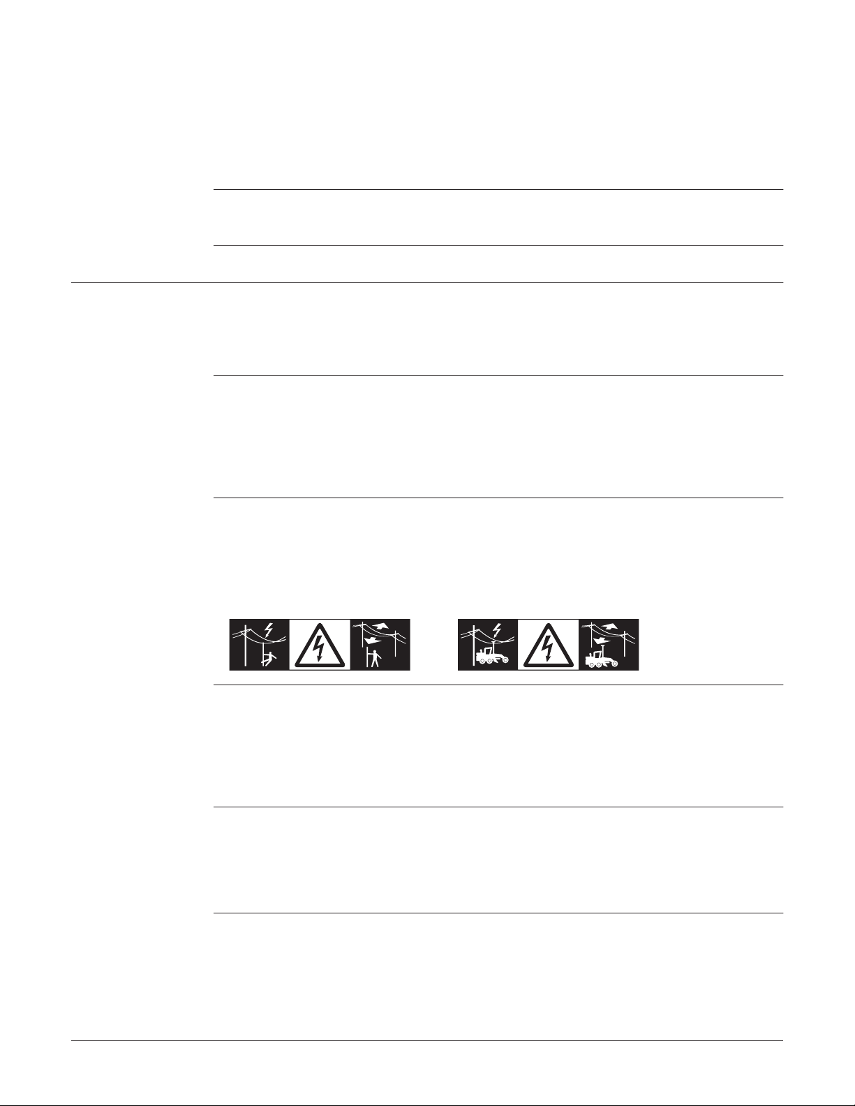
Because of the risk of electrocution, it is dangerous to use poles and extensions in the
vicinity of electrical installations such as power cables or electrical railways.
Precautions:
Keep at a safe distance from electrical installations. If it is essential to work in this
environment, first contact the safety authorities responsible for the electrical installations and follow their instructions.
WARNING
WARNING
CAUTION
iCON gps 80, Safety Directions
During dynamic applications, for example stakeout procedures there is a danger of
accidents occurring if the user does not pay attention to the environmental conditions
around, for example obstacles, excavations or traffic.
Precautions:
The person responsible for the product must make all users fully aware of the existing
dangers.
Inadequate securing of the working site can lead to dangerous situations, for example
in traffic, on building sites and at industrial installations.
Precautions:
Always ensure that the working site is adequately secured. Adhere to the regulations
governing safety, accident prevention and road traffic.
If the accessories used with the product are not properly secured and the product is
subjected to mechanical shock, for example blows or falling, the product may be
damaged or people can sustain injury.
9
Page 10

Precautions:
When setting-up the product, make sure that the accessories are correctly adapted,
fitted, secured, and locked in position.
Avoid subjecting the product to mechanical stress.
WARNING
DANGER
If the product is used with accessories, for example masts, staffs, poles, you may
increase the risk of being struck by lightning.
Precautions:
Do not use the product in a thunderstorm.
If the product is used with accessories, for example on masts, staffs, poles, you may
increase the risk of being struck by lightning. Danger from high voltages also exists
near power lines. Lightning, voltage peaks, or the touching of power lines can cause
damage, injury and death.
Precautions:
• Do not use the product in a thunderstorm as you can increase the risk of being
struck by lightning.
• Be sure to remain at a safe distance from electrical installations. Do not use the
product directly under or close to power lines. If it is essential to work in such an
environment contact the safety authorities responsible for electrical installations
and follow their instructions.
• If the product has to be permanently mounted in an exposed location, it is advisable to provide a lightning conductor system. A suggestion on how to design a
lightning conductor for the product is given below. Always follow the regulations in
force in your country regarding grounding antennas and masts. These installations
must be carried out by an authorised specialist.
• To prevent damages due to indirect lightning strikes (voltage spikes) cables, for
example for antenna, power source or modem should be protected with appropriate protection elements, like a lightning arrester. These installations must be
carried out by an authorised specialist.
• If there is a risk of a thunderstorm, or if the equipment is to remain unused and
unattended for a long period, protect your product additionally by unplugging all
systems components and disconnecting all connecting cables and supply cables, for
example, instrument - antenna.
Lightning conductors
iCON gps 80, Safety Directions
Suggestion for design of a lightning conductor for a GNSS system:
1) On non-metallic structures
Protection by air terminals is recommended. An air terminal is a pointed solid or
tubular rod of conducting material with proper mounting and connection to a
conductor. The position of four air terminals can be uniformly distributed around
the antenna at a distance equal to the height of the air terminal.
The air terminal diameter should be 12 mm for copper or 15 mm for aluminium. The
height of the air terminals should be 25 cm to 50 cm. All air terminals should be
connected to the down conductors. The diameter of the air terminal should be kept
to a minimum to reduce GNSS signal shading.
2) On metallic structures
Protection is as described for non-metallic structures, but the air terminals can be
connected directly to the conducting structure without the need for down conductors.
10
Page 11

Air terminal
arrangement, plan
view
GS_039
a
b
c
a) Antenna
b) Support structure
c) Air terminal
Grounding the
instrument/antenna
CAUTION
WARNING
a
b
c
d
a) Antenna
b) Lightning conductor array
c) Antenna/instrument connection
GS_040
During the transport, shipping or disposal of batteries it is possible for inappropriate
mechanical influences to constitute a fire hazard.
Precautions:
Before shipping the product or disposing of it, discharge the batteries by running the
product until they are flat.
When transporting or shipping batteries, the person in charge of the product must
ensure that the applicable national and international rules and regulations are
observed. Before transportation or shipping contact your local passenger or freight
transport company.
High mechanical stress, high ambient temperatures or immersion into fluids can cause
leakage, fire or explosions of the batteries.
Precautions:
Protect the batteries from mechanical influences and high ambient temperatures. Do
not drop or immerse batteries into fluids.
e
d) Metallic mast
e) Connection to earth
WARNING
WARNING
CAUTION
If battery terminals are short circuited e.g. by coming in contact with jewellery, keys,
metalized paper or other metals, the battery can overheat and cause injury or fire, for
example by storing or transporting in pockets.
Precautions:
Make sure that the battery terminals do not come into contact with metallic objects.
Incorrect fastening of the external antenna to vehicles or transporters poses the risk
of the equipment being broken by mechanical influence, vibration or airstream. This
may result in accident and physical injury.
Precautions:
Attach the external antenna professionally. The external antenna must be secured
additionally, for example by use of a safety cord. Ensure that the mounting device is
correctly mounted and able to carry the weight of the external antenna (>1 kg) safely.
Beware of inadequate steering if machine is defective like after a crash or other
damaging events or alterations to the machine.
Precautions:
Periodically perform control measurements and field adjustments on the machine as
specified in the User Manual. While working, construction and grading should be
checked by appropriate means, for example spirit level, tachymeter, before and after
important measuring tasks.
iCON gps 80, Safety Directions
11
Page 12

WARNING
While steering or navigating the machine accidents can occur due to a) the operator
not paying attention to the surroundings (persons, ditches, traffic, etc.), or b)
malfunctions (… of a system component, interference, etc.).
Precautions:
The operator assures that the machine is operated, guided and monitored by a qualified user (e.g. driver). The user has to be able to take emergency measures, for
example an emergency stop.
WARNING
WARNING
If the product is improperly disposed of, the following can happen:
• If polymer parts are burnt, poisonous gases are produced which may impair health.
• If batteries are damaged or are heated strongly, they can explode and cause
poisoning, burning, corrosion or environmental contamination.
• By disposing of the product irresponsibly you may enable unauthorised persons to
use it in contravention of the regulations, exposing themselves and third parties to
the risk of severe injury and rendering the environment liable to contamination.
Precautions:
The product must not be disposed with household waste.
Dispose of the product appropriately in accordance with the national
regulations in force in your country.
Always prevent access to the product by unauthorised personnel.
Product-specific treatment and waste management information can be downloaded
from the Leica Geosystems home page at http://www.leicageosystems.com/treatment or received from your Leica Geosystems distributor.
Only Leica Geosystems authorised service workshops are entitled to repair these products.
1.6 Electromagnetic Compatibility EMC
Description The term Electromagnetic Compatibility is taken to mean the capability of the product
to function smoothly in an environment where electromagnetic radiation and electrostatic discharges are present, and without causing electromagnetic disturbances to
other equipment.
WARNING
CAUTION
iCON gps 80, Safety Directions
Electromagnetic radiation can cause disturbances in other equipment.
Although the product meets the strict regulations and standards which are in force in
this respect, Leica Geosystems cannot completely exclude the possibility that other
equipment may be disturbed.
There is a risk that disturbances may be caused in other equipment if the product is
used with accessories from other manufacturers, for example field computers,
personal computers or other electronic equipment, non-standard cables or external
batteries.
Precautions:
Use only the equipment and accessories recommended by Leica Geosystems. When
combined with the product, they meet the strict requirements stipulated by the guidelines and standards. When using computers or other electronic equipment, pay attention to the information about electromagnetic compatibility provided by the manufacturer.
12
Page 13

CAUTION
Disturbances caused by electromagnetic radiation can result in erroneous measurements.
Although the product meets the strict regulations and standards which are in force in
this respect, Leica Geosystems cannot completely exclude the possibility that the
product may be disturbed by intense electromagnetic radiation, for example, near
radio transmitters, two-way radios or diesel generators.
Precautions:
Check the plausibility of results obtained under these conditions.
CAUTION
Radios or Digital
Cellular Phones
WARNING
If the product is operated with connecting cables attached at only one of their two
ends, for example external supply cables, interface cables, the permitted level of electromagnetic radiation may be exceeded and the correct functioning of other products
may be impaired.
Precautions:
While the product is in use, connecting cables, for example product to external battery,
product to computer, must be connected at both ends.
Use of product with radio or digital cellular phone devices:
Electromagnetic fields can cause disturbances in other equipment, in installations, in
medical devices, for example pacemakers or hearing aids and in aircraft. It can also
affect humans and animals.
Precautions:
Although the product meets the strict regulations and standards which are in force in
this respect, Leica Geosystems cannot completely exclude the possibility that other
equipment can be disturbed or that humans or animals can be affected.
• Do not operate the product with radio or digital cellular phone devices in the vicinity
of filling stations or chemical installations, or in other areas where an explosion
hazard exists.
• Do not operate the product with radio or digital cellular phone devices near to
medical equipment.
• Do not operate the product with radio or digital cellular phone devices in aircraft.
iCON gps 80, Safety Directions
13
Page 14

1.7 FCC Statement, Applicable in U.S.
Mododel:
el:
qui
ui
p. N
p. N
o.:o.:
1234
r: 9
V-36V no
l /
3A m
ax.
a Ge
a Ge
osysosys
osys
osys
ys
osys
osys
osy
sy
sys
osys
osy
y
y
y
y
tems
temsAGAG
-9
435
Heer
brug
g
nu
fact
ured
ured
XX
deinSwit
Swit
zerl
zerl
: 1
: 1 11
2345
2345
2345234377Art.
Art
805
2xx2xx
IDID: R
: R
R
: RRRR: R
: R
: R
FD-
FD-
FD-DICG
ICGICCGCCGCGCG
CG
ICG
G
G
80N
80NNN
80N
8
8
G
G
GGG
G
G
31
77A
77A
77A77
-IC
-IC
G80
G80G88
NGNGNGNGNGG
ins t
s
t
stransm
ransm
ransm
ransm
ransm
m
itter
itter
itter
itter
oumod
modu
mod
modummmle:
le:
le:lele
-ID
: N: N:NNN7NM7NM
7NMNNM04024-MC
-MC
73073044
s
dev
devicdevic
e com
e com
e com
com
comome com
com
m
pliesplies
pl
plies
plies
plies
ies
plies
ies
plies
i
with
wthwith
wi
with
withwwi
hww
it
partpart
rtpa
15 o15 o1515 15f thef the
the
thehef the
the
f th
the
FCC
FCC
FCC
RulesRules
Ru
e
tion
tion
tion
tionttio
tion
tion
tio
n
s suis su
s ss sususs su
bject
bject
bject
bje
ject
ectec
to t
to totottot
e foe eff
llowi
llowi
llowi
lowol
ng twng tw
w
ng
g twtwtw
ng tw t
t
o con
o con
o c
o c
con
o cono o coon
ditioditio
ditio
ditio
ditio
itio
itio
tiooditio
t
ns:
ns:
ns:
ns:
s
T
his dhis d
is ds eviceevice
v
i
vic
c
e
may
a
may
a
y
y
ay
not cnot c
ot c
no
t c
ottc
c
ause ause
ause
usesuse
s
e
s
e
harmf
harmf
harmf
harm
harmfhaharm
harm
arm
ha
arf
a
ul inul in
l in
l in
in
n n
terfe
terfe
terf
ter
terf
terf
terfe
ter
terferferf
eeee
rence
rencerence
re
re
en
nce
e
c
eee
c
, and, and
, and
, and
a
, andanand
, and
andnd
an
an
a
a
t
his d
d
s dsd
eviceevice
eviceeveviceveceus
acc
a
eae
c
pt an
pt an
pt an
pt a
an
pt
a
an
an
n
t
a
y inty int
y int
n
iiny i
tiin
t
i
t
int
y
y
y
erfererferfee
rfer
erfrf
r
ence
ence
enceec
enceeenccei
eceec
ved,
ved,
ved,
ved
ved
v
v
v
ved
,
ding ding
ding
ding
n
ng
ing
g
g
g
g
g
g
interninterinin
inte
te
interite
in
tertte
ter
in
iinr
ferenferenrr
nece thce th
ce th
ce th
ce th
e th
ce
ce th
e t
h
at maat ma
at ma
a
at ma
at ma
at ma
at ma
at ma
at ma
ma
a
ma
at ma
at m
a
t
a
y cauy cau
cau
cau
y c
ccyuc
y
y
yyse un
se un
uus
u
u
s
n
desir
desir
desir
desir
desiresdds
r
ed
ededed
e
e
edeeedd
tion.
tion.
tion
tion.ttio
n
iotitn
05679
05679
0567
05679
0067_004
_004
_004
_00
)
WARNING
WARNING
The greyed paragraph below is only applicable for products without radio, digital
cellular phone devices.
This equipment has been tested and found to comply with the limits for a Class B
digital device, pursuant to part 15 of the FCC rules.
These limits are designed to provide reasonable protection against harmful interference in a residential installation.
This equipment generates, uses and can radiate radio frequency energy and, if not
installed and used in accordance with the instructions, may cause harmful interference
to radio communications. However, there is no guarantee that interference will not
occur in a particular installation.
If this equipment does cause harmful interference to radio or television reception,
which can be determined by turning the equipment off and on, the user is encouraged
to try to correct the interference by one or more of the following measures:
• Reorient or relocate the receiving antenna.
• Increase the separation between the equipment and the receiver.
• Connect the equipment into an outlet on a circuit different from that to which the
receiver is connected.
• Consult the dealer or an experienced radio/TV technician for help.
Changes or modifications not expressly approved by Leica Geosystems for compliance
could void the user's authority to operate the equipment.
Labelling iCON gps
80
Labelling CGA60
005679_004
005690_001
Model: iCG8x
Equip. No.: 12345678
S.No.: 1234567
Art.No.: 8052xx
Power: 9V-36V nominal / 3A max.
Leica Geosystems AG
CH-9435 Heerbrugg
Manufactured: 20XX
Made in Switzerland
This device complies with part 15 of the FCC Rules.
Operation is subject to the following two conditions:
(1) This device may not cause harmful interference, and
(2) this device must accept any interference received,
including interference that may cause undesired
operation.
FCC ID: R FD-I CG80 NG
IC: 3177A-ICG80NG
Contains transmitter module:
FCC-I D: N7NM C7304
IC: 2417C-MC7304
Type: CGA60 Art. No.: 805284
Power: 4.5 - 18V DC / 50mA max.
Leica Geosystems AG
CH-9435 Heerbrugg
Made in Canada
CGA60
NMCU12345678F
S. No.: 12345678 HW Rev: X.XX
Manufactured: 20XX P/N:01018920
iCON gps 80, Safety Directions
14
Page 15
2 Description of the System
2.1 System Components
2.1.1 General Information
Description The Leica iCON gps 80 instrument and the Leica CGA60 GNSS antenna together with
dedicated accessories like the Quick Release Machine Bracket CMB6, a machine
computer, or an external radio offers you highest productivity and flexibility. For
example, Single GNSS configuration as well as Dual GNSS configuration is possible, but
the system also can be used in a Base Station configuration.
Two example configurations are shown in the following paragraphs.
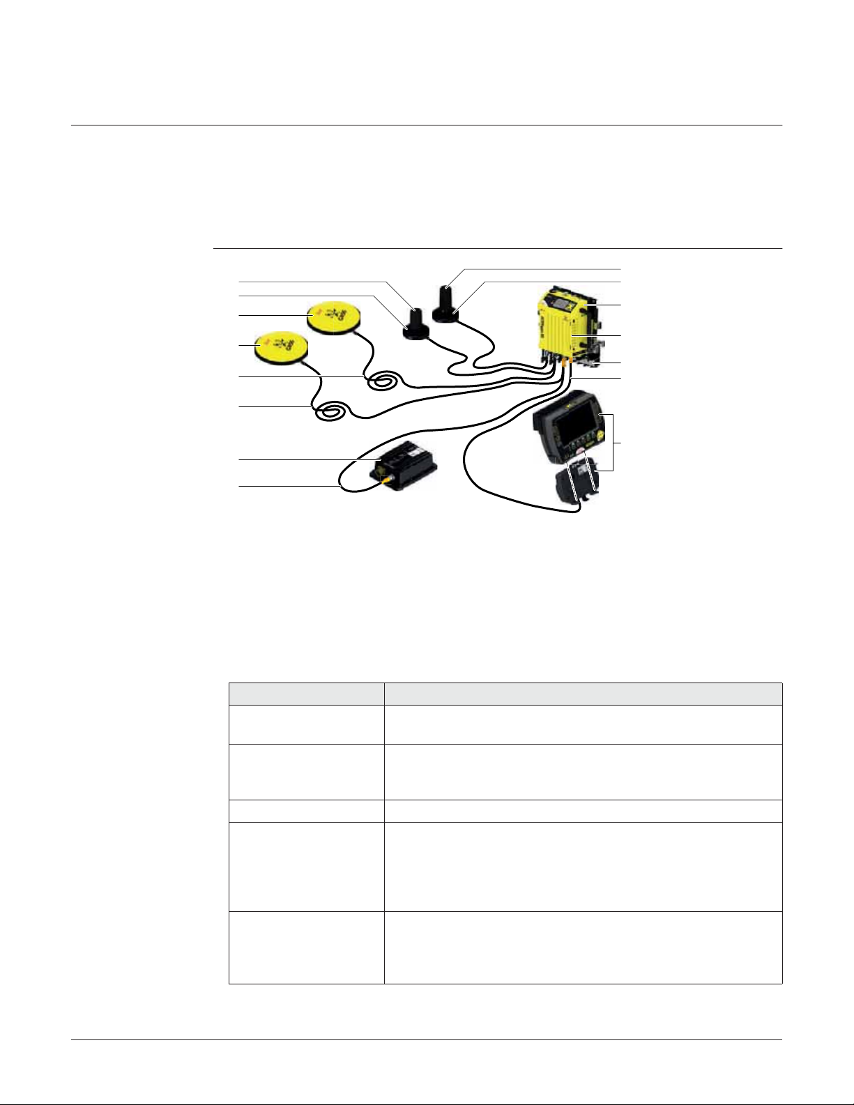
Main components,
Dual GNSS configuration with internal
modem
a
b
c
c
d
d
e
f
005698_001
a) Modem antenna CA26
b) CA22 Magnetic radio antenna mount,
2x
c) CGA60 Robust triple frequency GNSS
antenna, 2 x
d) CA16 Antenna cable, 10 m, 2 x
e) CAN junction box
g
b
h
i
j
k
l
f) CAN cable
g) Radio antenna CA12
h) iCG82 Instrument
i) Internal modem
j) Quick Release Machine Bracket CMB6
k) Cable for cradle 5Pin M12/open end,
5m
l) Machine PC
Component Description
iCG82 Instrument To calculate two positions from the computed ranges to all
CGA60 GNSS Antenna To receive the satellite signals from the GNSS satellites. This
Internal modem For correction data transfer radios/modems are used.
Quick Release Machine
Bracket CMB6
Machine PC To determine the position of the machine using measure-
iCON gps 80, Description of the System
visible GNSS (Global Navigation Satellite System) satellites.
Antenna is specified to the high environmental requirements
on mining and construction machines.
The special Quick Release Machine Bracket CMB6 can be used
for a fast withdrawal of the iCON gps 80 instrument. iCON
gps 80 needs to be pre-assembled with the left and right
clamping rail of the CMB6, while the Quick Release Base
Bracket must be installed on the machine.
ment information from the instrument and GNSS antenna
and for an automatic adjustment of the machine’s hydraulic
system.
15
Page 16
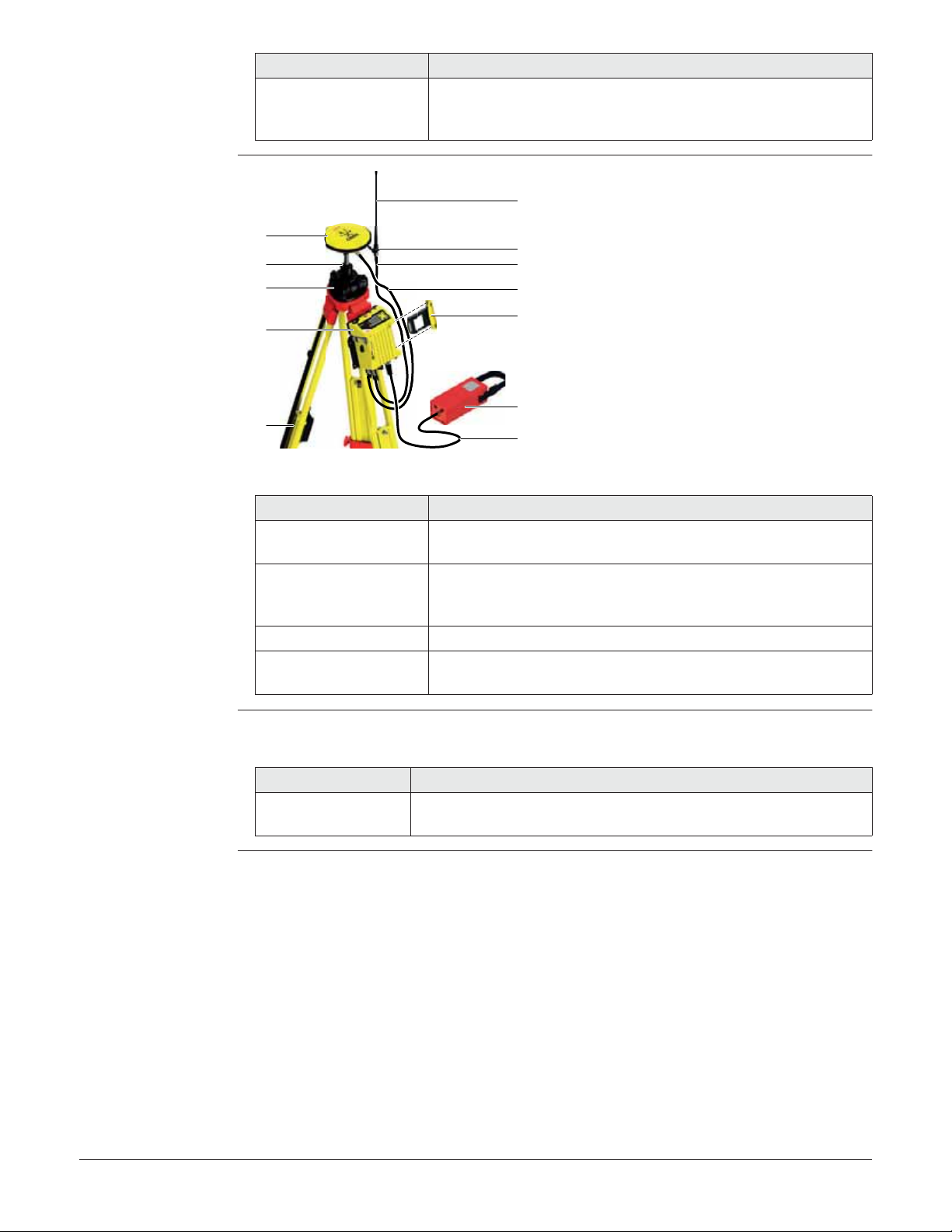
Main components,
Base Station configuration
Component Description
CAN junction box The components are connected directly to the standard
machine junction box and communication cables are
connected via the machine's own CAN bus.
f
a
b
c
d
g
h
i
j
a) CGA60 Robust triple
frequency GNSS antenna
b) GRT246 Carrier
c) CTB102 Tribrach
d) iCG81 Instrument
e) Tripod
f) GAT1 Gainflex radio antenna
g) GAD33 Arm 15 cm
h) GEV120 Antenna cable,
2.8 m
i) GEV120 Antenna cable,
k
e
l
005699_001
2.8 m
j) Satel Radio CCD14
k) External battery GEB371
l) MSC1259 Power cable
Component Description
iCG81 Instrument To calculate a position from the computed ranges to all
visible GNSS (Global Navigation Satellite System) satellites.
CGA60 GNSS Antenna To receive the satellite signals from the GNSS satellites. This
Antenna is specified to the high environmental requirements
on mining and construction machines.
Satel radio CCD14 For long-range data transmission.
Tripod, tribrach, carrier To setup the instrument and GNSS antenna as a Base
Station.
Satellite channels Depending on the satellite systems and signals configured, a maximum number of 120
channels is allocated.
Instrument Description
iCG81/iCG82 GPS, GLONASS, BeiDou and Galileo GNSS receiver, triple
frequency, code and phase, real-time capable
iCON gps 80, Description of the System
16
Page 17

Special features
iCON gps 80
iCON gps 80 instruments are equipped with several special features:
• Wide supply voltage range of 9 V to 36 V
• Voltage peak protection and reverse polarity protection
• Can be mounted on a machine in both the vertical and horizontal orientations
• Can be used near the sea
• Brackets for simple mountings
• Protection caps on connectors
• Display and keys for status and configuration
• Versatile connectivity including CAN, Serial RS232, Ethernet and Bluetooth
• USB host port for data transfer and firmware upgrade
• Integrated high speed LTE (4G) / HSPA (3.5G) / GPRS (2G) modem for countries
without 4G/3G
• Integrated radio options
• Single and dual GNSS variants
• Backwards compatibility: supports external GFU communication devices for cost
effective upgrade from legacy Leica systems
• Robust, compact aluminium housing
Special features
CGA60
Commands for
Remote Config
CGA60 antennas are equipped with several special features:
• Can be used near the sea
• Standard robust 5/8" Whitworth thread
• Robust TNC connector
• Future proof four constellation, triple frequency antenna element
• Robust, compact plastic housing
The iCON gps 80 instrument can be communicated:
• via the MPI protocol on the serial port P1 and Bluetooth.
• via the Leica Machine Control CAN Protocol on the CAN ports.
• via the Leica Machine Control Net Protocol on the Ethernet port, Serial P1 and Bluetooth.
Documentation for these communication protocols is available on request from the
Leica Geosystems representative.
iCON gps 80, Description of the System
17
Page 18

2.1.2 Power Concept
General Use the batteries, chargers and accessories recommended by Leica Geosystems to
ensure the correct functionality of the instrument.
Power options Power for the instrument is to be supplied externally. Up to two external power
supplies can be connected.
External power can be supplied by:
• 9 V to 36 V DC power supply (machine or vehicle) via a converter cable supplied by
Leica Geosystems.
• GEB371 battery connected via a cable.
• 110 V/240 V AC to 12 V DC power supply unit, supplied by Leica Geosystems.
iCON gps 80 can be powered using the CAN ports as well as the serial port P1.
iCON gps 80 can accept different voltages on the CAN and serial ports, for
example one main supply 24 V and one backup supply 12 V. However, the
instrument should never be connected with two different CAN input voltages,
as this may cause the instrument to power down and can potentially cause
damage to the internal electronics.
)
)
)
For permanent operations use Uninterruptible Power Supply units as a back-up in a
main power failure.
2.2 Unpacking the Container
Description Available delivery packages:
• Delivery box: when a single iCON gps 80 instrument was ordered. Includes the
instrument, the printed iCON gps 80 Quick Guide and the USB documentation card.
• A hard-top container comprising all items for a Single or Dual GNSS configuration.
• A hard-top container comprising all items for a Base Station setup.
iCON gps 80, Description of the System
18
Page 19

2.2.1 iCON gps 80 Dual GNSS Container
CTC4 Container
upper shell
The large-size CTC4 container comprises all items for the Single and Dual GNSS configurations.
a
b
c
d
e
005678_001
f
d
g
a
d) CA22 Magnetic radio antenna mount,
a) CGA60 Robust triple frequency GNSS
antenna, 2 x
b) Slope Sensor
c) CAN cable, 2 x
2x
e) Radio antenna CA12
f) CA16 Robust antenna cable, 2 x
g) Modem antenna CA26
CTC4 container
lower shell
Large-size CTC4 container configuration with Machine PC.
a
b
c
d
e
005677_001
a) iCON gps 80 Instrument
b) Left and right clamping rail of the Quick
Release Machine Bracket CMB6
c) GFU27 Radio modem
d) Allen key 2.5 mm
e) MS1 Industrial 1 GB USB memory stick
f) Manuals & USB documentation card
g) Machine PC
f
g
iCON gps 80, Description of the System
19
Page 20

2.2.2 iCON gps 80 Base Station Container
CCTC3 Container
upper shell
CCTC3 container
lower shell
The large-size CCTC3 container comprises all items for the Base Station setup.
a
b
c
d
e
005676_001
f
g
h
a) CGA60 Robust triple frequency GNSS
antenna
b) GAD32 Telescopic rod
c) GAT1 Radio antenna
d) CA15 Antenna cable, 5 m
a
b
c
e) MSC1259 Power cable
f) GAD33 Arm 15 cm
g) GHT36 Base for telescopic rod
h) GSZ4-1 Height hook
d
e
f
005675_001
a) iCON gps 80 Instrument
b) GFU27 Radio modem
c) Allen key 2.5 mm
d) MS1 Industrial 1 GB USB memory stick
e) CTB102 Tribrach
g
h
i
f) GAD34 Adapter antenna to extension
g) Manuals & USB documentation card
h) GRT246 Carrier
i) GAT18 Multiband GSM/UMTS antenna
iCON gps 80, Description of the System
20
Page 21
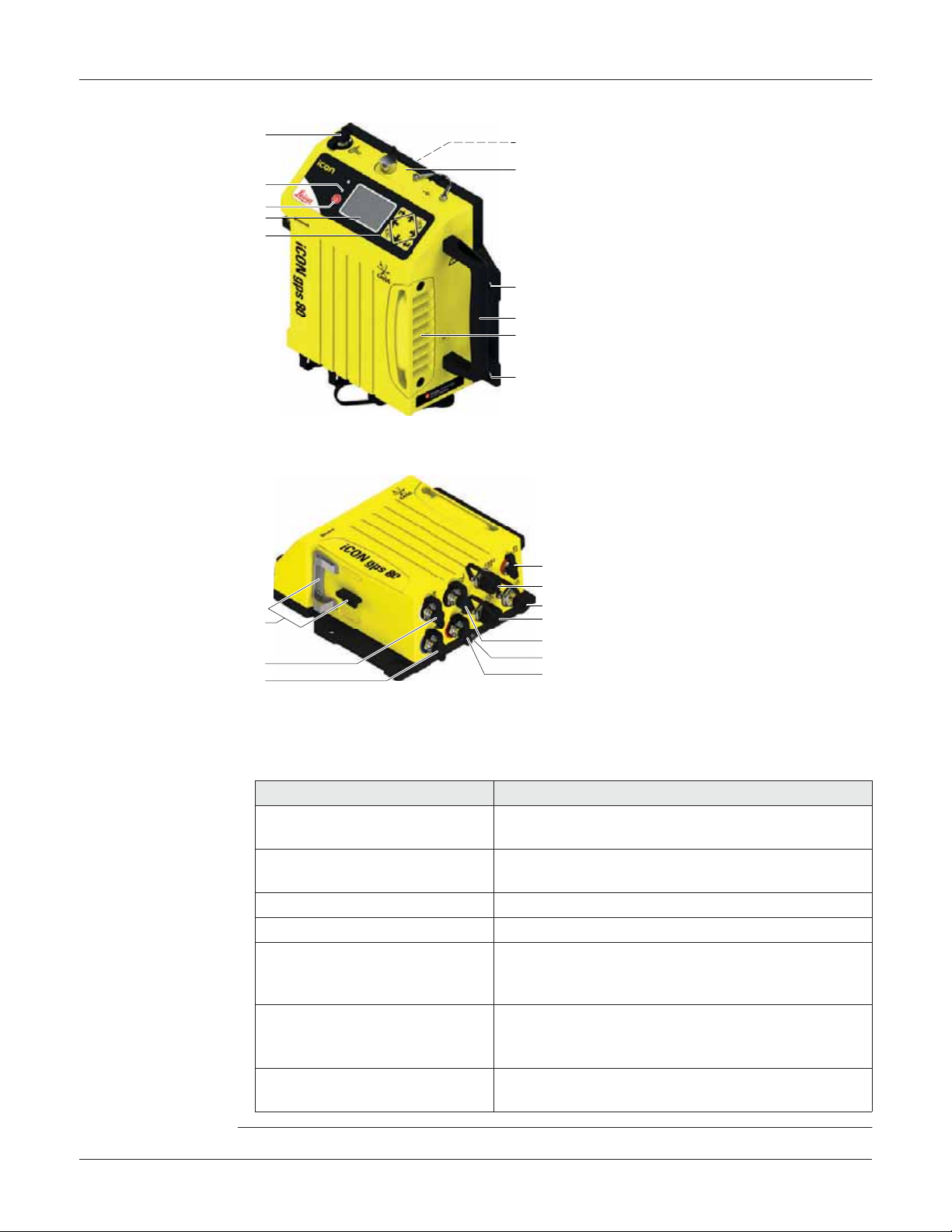
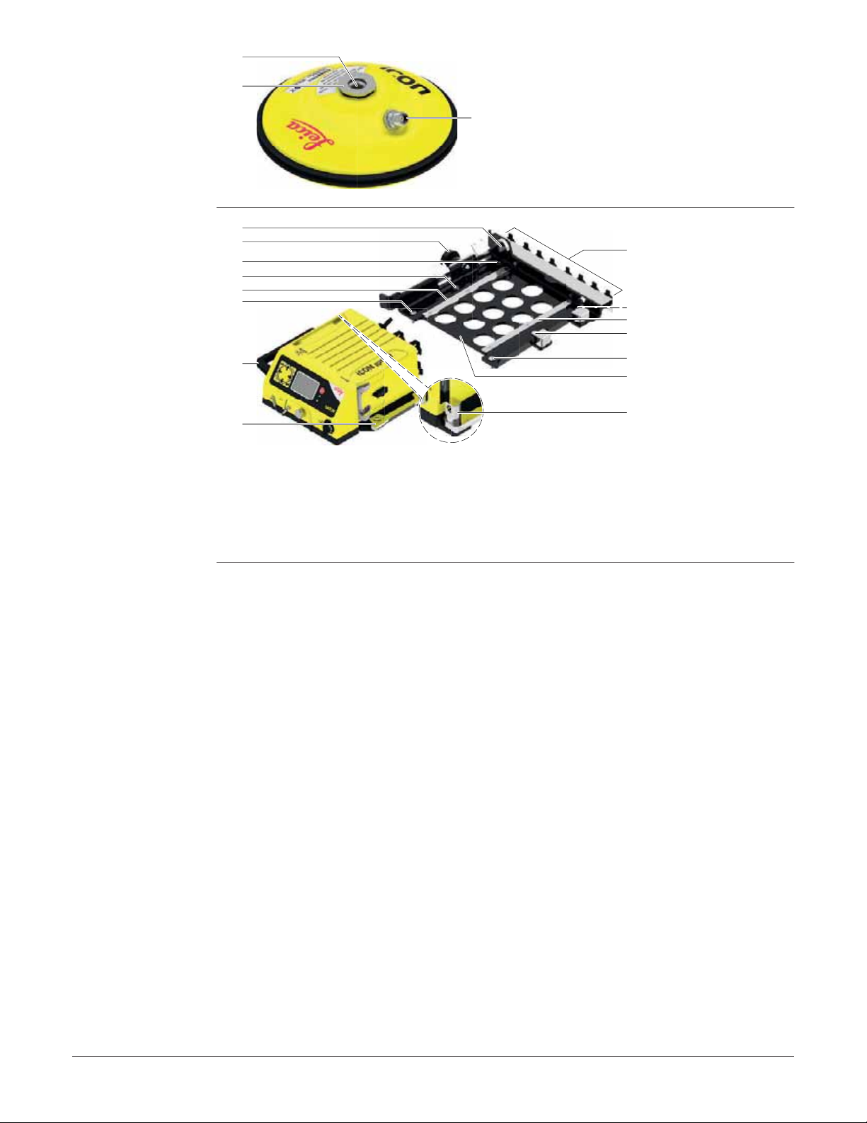
2.3 Instrument Components
iCG81/iCG82
components
Front view:
a
b
c
d
e
005681_001
Rear view:
a
b
c
005682_001
f
g
a) RS232 port P2
b) Power and status LED,
Ambient light sensor
c) ON/OFF button
d) Display
h
e) Keyboard
f) Tripod fastening clip
i
j
g) Cover for USB port
h) Mounting holes
i) Carrying handle, optional
h
accessory
j) Radio cover, SIM card and
slot-in-device compartment
a) Support for GFU device
b) External radio antenna
port
c) Primary External GNSS
d
e
f
g
h
i
j
antenna port
d) P1 Data/Power port
e) CAN1 Data/Power port
f) Ethernet port
g) CAN2 Data/Power port
h) External Modem
antenna port
i) Grounding screw
j) Secondary external
GNSS antenna port,
iCG82 only
Port Description
USB 2.0 USB A data port, for data exchange, software
P1 (8-pin LEMO 1, female) Power input, serial interface for data input/output,
P2 (8-pin LEMO 1, female) RS232 for connection of an external radio device.
RADIO For connection of an external radio antenna.
CAN1, CAN2 Power input and data input/output. CAN ports are
ANT1, ANT2 GNSS antenna input.
MODEM For connection of an external antenna for the
iCON gps 80, Description of the System
updates.
and PPS.
connected internally so connection order is not
important.
ANT1 is always the primary GNSS antenna and ANT2
is always the secondary (heading) GNSS antenna.
internal 4G modem.
21
Page 22
CGA60 components
a
b
005691_001
c
a) Whitworth thread, 5/8"
b) Mechanical reference plane
c) TNC female connector
CMB6 components
a
b
c
c
d
c
e
f
005862_002
a) Feed through for Padlock
b) Locking bolt
c) Mounting screws, for vehicle mounting
d) Guiding rail
g
c
d
c
c
h
i
e) Carrying handle, optional accessory for
iCON gps 80
f) Clamping rail
g) Dummy plugs for cable storage
h) Quick Release Base Bracket
i) Locking bolt for Padlock
iCON gps 80, Description of the System
22
Page 23
3 Using iCON gps 80
3.1 Power Supply
External power
supply only
)
)
• 9 V to 36 V DC power supply (machine or vehicle) via a converter cable supplied by
Leica Geosystems.
• The iCON gps 80 instrument can be powered via the CAN ports as well as Port 1.
• A GEB371 battery can also be connected via cable.
For permanent operations use Uninterruptible Power Supply units as a back-up in a
main power failure.
In general, all installation works - including the setting up of a permanent power supply
- must be done by a dedicated installation specialist. Please contact the local selling
unit or dealer for further information.
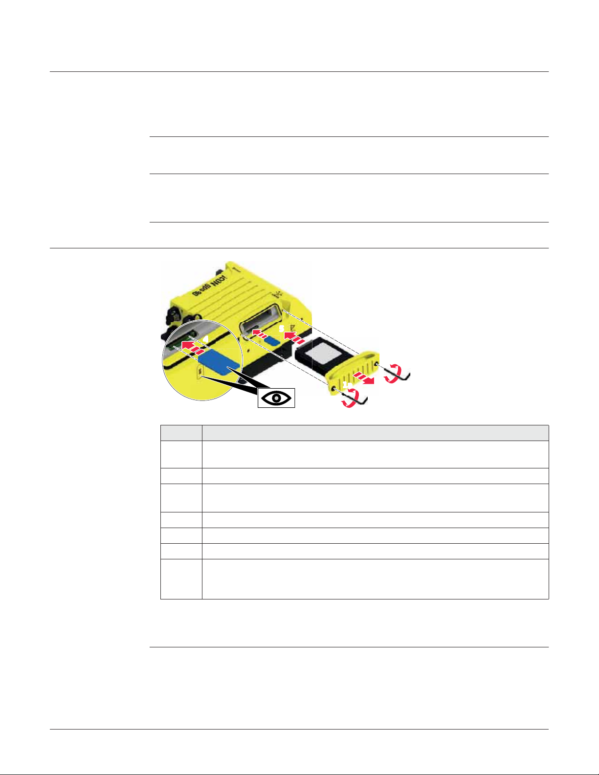
3.2 Installing a SIM Card
Insert and remove
the SIM card stepby-step
4
005737_002
3
5
1b
6b
1a 2
6a
60 Ncm
Step Description
)
1. Loosen the screws of the Radio cover with the supplied Allen key.
2. Remove the Radio cover.
3. Orientate the SIM card as illustrated.
4. Insert the SIM card into the card slot and push it in until it locks into place.
5. Place the Radio cover back into position.
6. Tighten the screws of the Radio cover, with maximum 60 Ncm.
)
Ensure the instrument is placed in it’s fixed position or place it onto a stable
surface.
)
)
To remove the SIM card push the card in again, then it pops out and can be
removed.
The indents on the Radio cover allow to grip and pull for removal.
Secure the screws with Loctite 243 or a similar product to ensure
that the instrument is waterproof.
iCON gps 80, Using iCON gps 80
23
Page 24

3.3 Slot-in-Device
3
4
5a
5b
Internal radios Following internal radios can be used with the instrument:
Radio Device
Satel TA13 CCD7
Intuicom 900SLR CCD8
Insert and remove
slot-in-device stepby-step
6
1b
7b
1a 2
7a
005738_002
60 Ncm
Step Description
)
1. Loosen the screws of the Radio cover with the supplied Allen key.
2. Remove the Radio cover.
3. Place the slot-in-device into position to the Radio cover.
4. Place the mounting bracket into position.
5. Tighten the screws.
6. Place the Radio cover back into position.
7. Tighten the screws of the Radio cover, with maximum 60 Ncm.
)
Ensure the instrument is placed in it’s fixed position or place it onto a stable
surface.
)
)
For the equipment setup as real-time base station with radio, it's recommended to use an external radio antenna mounted on a second tripod. This
increases the height of the radio antenna and therefore maximises radio
coverage. Please contact the local selling unit or dealer for further information.
The indents on the Radio cover allow to grip and pull for removal.
Secure the screws with Loctite 243 or a similar product to ensure
that the instrument is waterproof.
iCON gps 80, Using iCON gps 80
24
Page 25

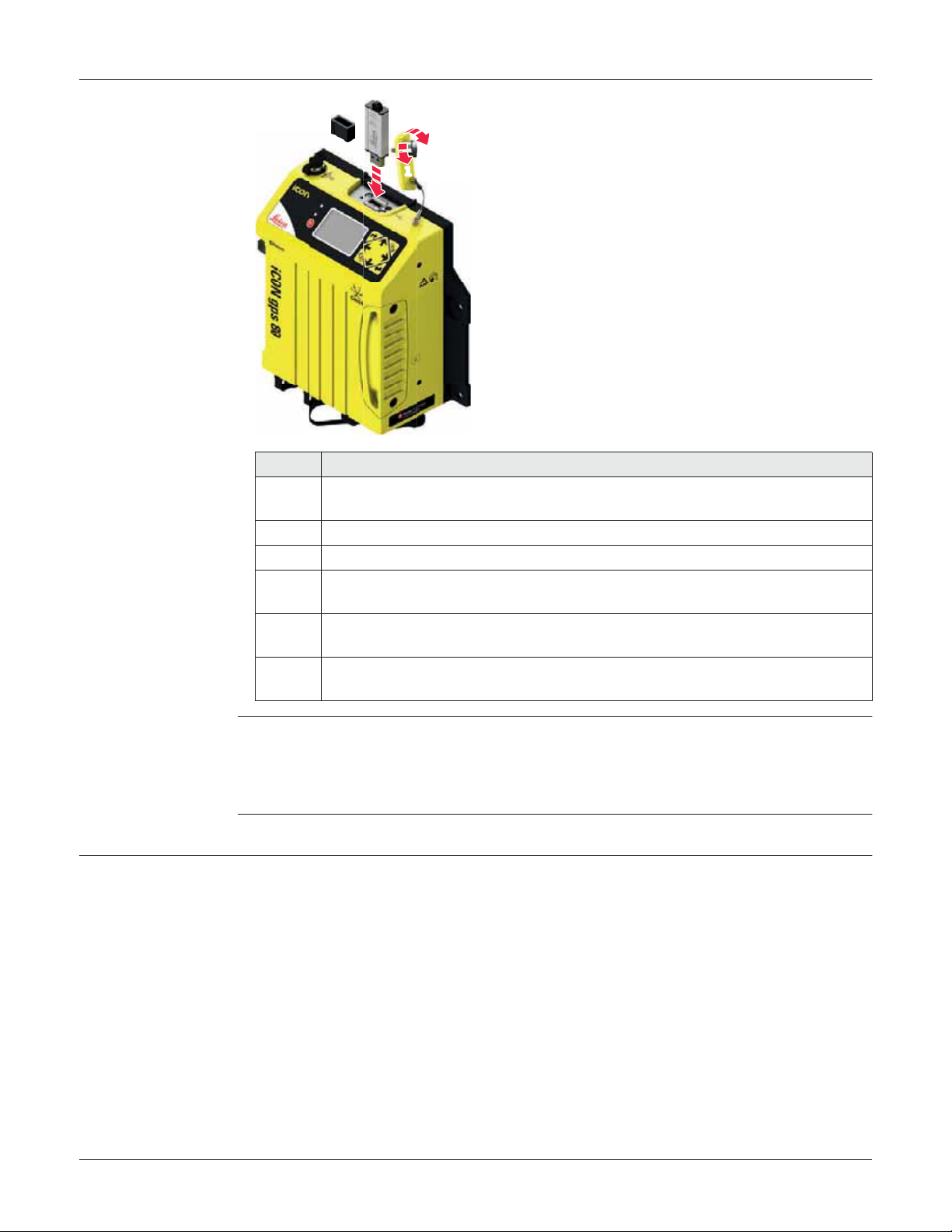
3.4 External Radios
Devices fitting into
a clip-on-housing
Attach and detach a
clip-on-housing
step-by-step
Radios fitting into a clip-on-housing
Radio Clip-on-housing
Intuicom 1200DL, transceive 1200DL
Pacific Crest PDL, receive GFU15
Satelline 3AS, transceive GFU14
Satelline M3-TR1, transceive GFU27
TFR-300L, receive no GFU number
Pacific Crest radio modems
Pacific Crest radio modems must be ordered directly from your local Pacific Crest Office
or Representative.
PDL receive only modems built into the Leica GFU radio housing with 12.5 or 25 kHz
channel spacing within the following frequency bands are available:
• 410 - 430 MHz
• 450 - 470 MHz
)
Pacific Crest ADL, transceive, can be used but is not available in a clip-onhousing.
5b
3
• 430 - 450 MHz
• 223 - 235 MHz
6
7
5a
005861_001
Step Description
)
1. Flip the protection cap of port P2 aside.
2. Ensure that the connector on the clip-on-housing fits to port P2 on the
3. Place the clip-on-housing into position such that the guide rails for the clip-
4. Slide the clip-on-housing towards the instrument front panel to the guide
5. Apply slight pressure to the clip-on-housing towards the instrument side
Ensure the instrument is placed in it’s fixed position or place it onto a stable
surface.
instrument front panel.
on-housing on the instrument and the guide rails on the clip-on-housing are
aligned.
rails on the instrument.
and slide the clip-on-housing towards the instrument front panel until the
connector is plugged into port P2.
4
1
2
8
9
iCON gps 80, Using iCON gps 80
25
Page 26
Step Description
6. On the top side of the clip-on-housing, turn the screw clockwise, as shown
by the symbols on the screw, to lock the clip-on-housing to the instrument.
7. Screw the radio antenna or a radio antenna cable onto the clip-on-housing.
8. To detach the clip-on-housing, turn the screw anticlockwise on the top side
of the clip-on-housing, as shown by the symbols on the screw, to unlock the
clip-on-housing from the instrument.
9. Slide the clip-on-housing away from the instrument front panel until the
connector is unplugged from port P2 and the guide rails are released.
10. Place the protection cap on port P2 again.
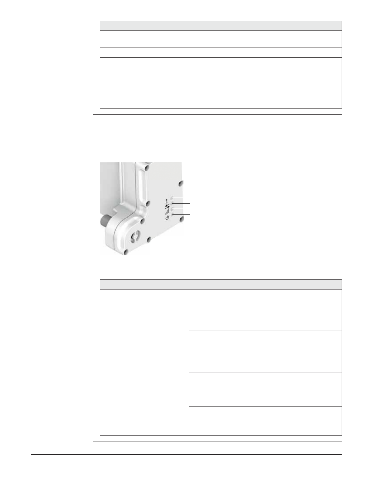
LED indicators Description
Each clip-on-housing for a radio or digital cellular phones has Light Emitting Diode
indicators on the bottom side. They indicate the basic device status.
Diagram
a
b
c
d
a) Mode LED, available for Satelline
3AS and M3-TR1
b) Data transfer LED
c) Signal strength LED
005936_001
d) Power LED
Description of the LEDs
IF the on is THEN
Mode LED GFU14 with Satel-
line 3AS, GFU27
with Satelline M3-
red the device is in the programming
mode controlled from the PC via
cable.
TR1
Data
transfer
LED
Signal
strength
LED
any device off data is not being transferred.
green or flashing
data is being transferred.
green
GFU15 with
Pacific Crest PDL
red or flashing red the communication link, Data
Carrier Detection, is okay on the
roving instrument.
off the DCD is not okay.
GFU14 with Satelline 3AS, GFU27
with Satelline M3TR1
red or flashing red the communication link, Data
Carrier Detection, is okay on the
roving instrument.
off the DCD is not okay.
Power LED any device off power is off.
green power is okay.
iCON gps 80, Using iCON gps 80
26
Page 27
3.5 Using USB Memory Devices
Insert and remove a
USB Memory device
step-by-step
005749_001
Step Description
)
1. Loosen the knurled screw of the USB port cover.
2. Flip the cover aside.
3. Slide the USB Memory device firmly into the USB host port until it clicks into
)
)
Ensure the instrument is placed in it’s fixed position or place it onto a stable
surface.
position.
Take care not to damage the USB Memory device when moving the iCON gps
80 or when handling around the device.
It’s recommended to close the USB port cover when no USB Memory device
is used.
2
1
3
Preconditions for
using USB Memory
devices
• USB Memory devices must be formatted in the FAT or FAT32 format.
• To import data from a USB Memory device to the iCON gps 80 appropriate folders
must be created on the USB device and the files placed in the correct folder. Refer
to "6.6 Import, Export, or Delete Data" for further information.
3.6 Quick Release Machine Bracket CMB6
Installation information
iCON gps 80, Using iCON gps 80
Installation of the Quick Release Machine Bracket CMB6 should be carried out in a way
to respect following aspects:
• Stable mounting construction, in a position without interfering the operators work
space.
• The Quick Release Base Bracket as part of the CMB6 must be installed on the
machine or the desired installation spot accordingly, either using the Magnetic
Mount or bolted.
• Easy and secure access to attach and detach the iCON gps 80 instrument.
• Easy and secure access to all connected cables.
• Easy access to the iCON gps 80 keys and a clear view on the display.
27
Page 28

)
Like all other installation works, the installation of the CMB6 must be done by
a dedicated installation specialist. Please contact the local selling unit or dealer
for further information.
Attach and detach
the iCON gps 80
step-by-step
Attach the iCON gps 80
3
1
2
005863_002
Step Description
)
1. Insert the iCON gps 80 into position on the "fixed jaw" side of the Quick
2. Lower the instrument on the "spring jaw" side of the CMB6, until the locking
3. If applicable, attach a padlock to the feed through and lock up.
4. Connect all cables needed for the current configuration to the corre-
)
5. When the cables have been stored on a dummy plug before, close the
iCON gps 80 needs to be pre-assembled with the left and right clamping rail
of the Quick Release Machine Bracket CMB6.
The Quick Release Base Bracket must be pre-installed on the machine or the
desired installation spot accordingly, either using the Magnetic Mount or
bolted.
Release Machine Bracket CMB6.
bolt snaps into place.
sponding connectors. Cables and connectors are colour coded, for easy
assignment.
Ensure to connect all cables to the corresponding connector, to protect the
instruments from damage.
dummy plug with its protection cap.
iCON gps 80, Using iCON gps 80
28
Page 29
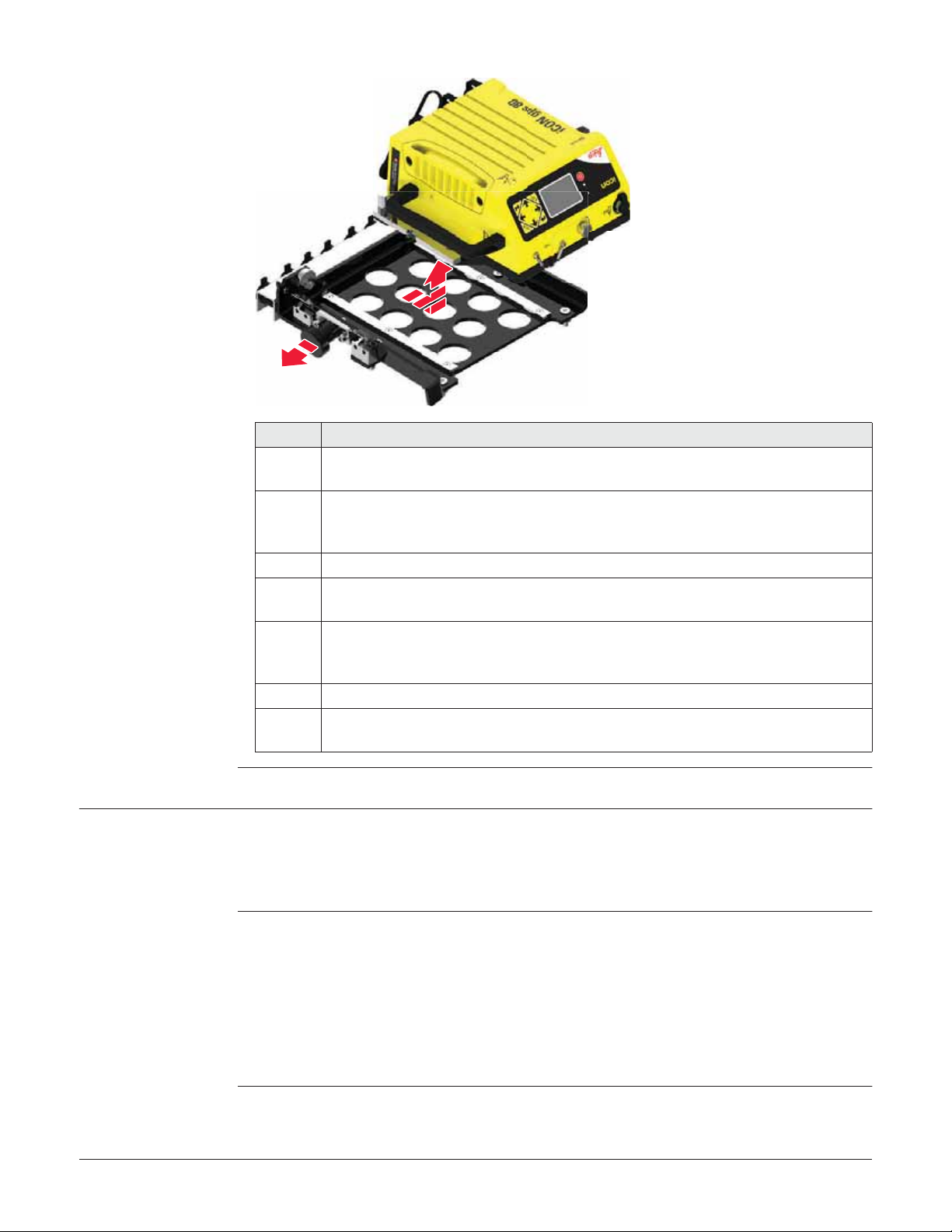
Detach the iCON gps 80
4
3
006355_001
Step Description
)
1. To detach the iCON gps 80, first detach the connected cables one by one
2. If applicable, unlock and detach the padlock.
3. Withdraw the locking bolt from its locking position and arrest it in open posi-
4. Slide the instrument on the guiding rails of the Quick Release Machine
5. Refit the protection caps of the iCON gps 80 plugs.
)
Before detaching the iCON gps 80, ensure the instrument is properly shut
down and power switched off.
and store them onto a proper dummy plug. Connector positions and dummy
plugs are symbol coded, for easy assignment.
tion by rotating.
Bracket CMB6 out of the guides and remove the instrument. Take care not
to cant the upper and lower part of the CMB6.
The plugs of the iCON gps 80 and the CMB6 should always be covered using
the corresponding protection cap, when no cable is plugged in.
3.7 Installation on a Machine
)
)
iCON gps 80, Using iCON gps 80
In general, all installation works must be done by a dedicated installation specialist.
Please contact the local selling unit or dealer for further information.
The installation information within this User Manual is indicated to increase the operators understanding of the system and its maintaining.
Before installation:
• Please observe the maximum vibration and ambient temperature values indicated
in chapter "9 Technical Data".
• Check that all parts needed are delivered. Refer to "2.2 Unpacking the Container"
for further information.
• It is strongly recommended that you bench test all components before commencing
installation on the actual machine to make sure that all components are fully operational.
29
Page 30

Installation location The iCON gps 80 instrument should preferably be installed either inside a compart-
ment just behind the cabin or in the machine cabin itself. If the machine has no space
inside a weather proof compartment or cabin, the instrument is to be installed only
on components that have no direct connection to the machine tool and/or are positioned separately from the tool or at locations that lie in the safe area of the mechanically moving components. Further, the instrument is to be installed so that it is
protected from mechanical influences, for example stoning.
Examples of a correctly placed instrument.
006174_001
005939_001
)
The product must not be installed on the tool of the machine and/or on
mechanical components that move the tool. Tools include for example bucket
of excavator, blade of dozer, screed of paver. Mechanical parts include for
example boom and stick of an excavator, hydraulic cylinder of a dozer or tow
arm of an asphalt paver.
Further, the instrument must not be installed near chassis, chain gear, wheels
or on engine components connected to the engine itself. The cases stated are
intended simply as examples.
iCON gps 80, Using iCON gps 80
30
Page 31

Installation direction
Fastening • The iCON gps 80 instrument must have supports beneath all mounting holes and
• For inside assembly, the iCON gps 80 instrument must be installed either vertically
with the connectors pointing upwards/downwards or horizontally on a flat plane.
Easy access to the keys and a clear view on the display should be guaranteed.
• For outside assembly, it is strongly recommended to install the instrument vertically
with the connectors pointing downwards, in case this is not possible horizontally
on a flat plane, but never with the connectors pointing upwards.
should be fastened with four M6 bolts (or equivalent).
• The Quick Release Machine Bracket CMB6 is easy to handle and forms a secure
mounting option for the instrument. The Quick Release Base Bracket as part of the
CMB6 must be installed on the machine, either using the Magnetic Mount or bolted.
Quick Release
Machine Bracket
Electrical grounding The electrical grounds of a Machine may be at different potentials either due to other
The special Quick Release Machine Bracket CMB6 can be used for a fast withdrawal of
the iCON gps 80 instrument.
)
large current electronic devices on the machine or when different grounds of the
machine are isolated in service or welding operations.
Different DC and RF noise may exist at different points in the machine which is out of
the control of Leica Geosystems. Such noise may have a negative effect on the satellite tracking performance of the iCON gps 80.
For this reason, it is best that all external antennas connected to the iCON gps 80,
including the GNSS antenna(s), radio antenna and modem antenna, are isolated from
the machine. This avoids additional ground paths being introduced.
)
)
The CMB6 should be be installed in a location that allows easy releasing and
simple removing of the iCON gps 80 instrument. Refer to "3.6 Quick Release
Machine Bracket CMB6" for further information.
In an ideal installation, with isolated antennas, the connection of the
grounding pin on the rear panel of the iCON gps 80 to the machine should not
be required.
It is extremely important to disconnect all cables from the iCON gps 80
before starting any welding operations on the machine. Otherwise the
instrument may be damaged beyond repair.
iCON gps 80, Using iCON gps 80
31
Page 32

Installation of GNSS
antennas
For best results, it is recommended to mount the two GNSS antennas according to
following guidelines:
• separated as far as possible,
• at approximately the same height,
• with the TNC connectors orientated in approximately the same direction, and
• ensuring an unobstructed view of the sky.
Installation on an excavator:
• Install the two GNSS antennas on the masts in the back of the machine.
• One mast should be placed on each side of the machine. Be aware of heat from
the exhaust.
Installation of
external radio
005940_001
Installation on a grader/dozer:
• Install the GNSS antenna on the mast on the blade. Be aware of heat from the
exhaust.
005941_001
In case the external GFU radio cannot be mounted directly on the iCON gps 80 due to
space limitations, then a special bracket for proper mounting can be used.
GFU bracket: MMB1250, GFU Bracket on Machine
iCON gps 80, Using iCON gps 80
32
Page 33

Installation of
antennas for
internal/external
radios and modems
• External antennas with a magnetic mount can be used and installed on the roof of
the cabin.
• This will increase the radio signal and therefore the reception of correction signals
from a base station or when using a NTRIP solution.
005942_001
Cable installation • Ensure that the cables between iCON gps 80 and CGA60 antenna in particular are
installed so as to prevent them from becoming bent and stretched.
• It is strongly recommended to use strain relief brackets.
• Route the cable as directly as possible and avoid crossing cables.
• Be sure not to tie the cables into “hot” hydraulic hoses.
)
Connecting the wrong antenna to the wrong connector may cause damage to
the antennas. In order to minimise the chance of connecting the incorrect
external antenna, the four TNC connectors are colour coded. Cables with corresponding colours are available.
The colour coding is as follows:
ab
006150_001
cd
a) White: Radio
b) Black: Modem
c) Blue: GNSS Antenna 1
d) Red: GNSS Antenna 2
iCON gps 80, Using iCON gps 80
33
Page 34

3.8 Antenna Heights
3.8.1 Understanding Antenna Heights
Description The height of the GNSS antenna above a point consists of three components:
• the vertical or slope height reading,
• the vertical offset,
• the vertical phase centre offset.
For most operations, pre-configured standard settings in the instrument can be used.
They automatically take the vertical phase centre offsets into account.
MRP The antenna accepts vertical height readings to the Mechanical Reference Plane, MRP.
Vertical phase
centre variations
)
)
)
3.8.2 The Mechanical Reference Plane, MRP
Description The Mechanical Reference Plane:
MRP of the antenna The MRP for the CGA60 antenna is shown in the diagram.
These are handled automatically in the standard antenna records. The antenna calibrations to determine the phase centre variations were executed by Geo++® GmbH.
Pillar setup. For other than the GRT146 carrier, the dimensions must be determined
and the vertical offset must be adapted.
Tripod setup. For height measurement devices other than the height hook, the
dimensions must be determined and the vertical offset must be adapted.
Mast setup. The dimensions of the mast must be determined.
• is where the instrument heights are measured to.
• is where the phase centre variations refer to.
• varies for different instruments.
005752_001
iCON gps 80, Using iCON gps 80
a) The mechanical reference plane is
the underside of the threaded
a
metal insert.
34
Page 35

3.8.3 Measuring the Antenna Height for a Pillar Setup
Measuring the
antenna height pillar setup
Determining the
antenna height with
the GRT146 carrier
step-by-step
Setup type Antenna name The required measurement
Pillar CGA60 the vertical height reading to the MRP.
a
b
c
d
a) Mechanical reference plane MRP
b) Vertical phase centre offset for L1
c) Vertical phase centre offset for L2
d) Vertical Height Reading
005753_001
No vertical offset.
Step Description
1. Measure a height from the pillar benchmark to a surface on the carrier.
145.5 mm
36.5 mm 109 mm
005755_001
2. Use the appropriate measurement from the diagram above. Determine the
height difference between the measured surface on the carrier and where
the MRP of the antenna sits on the carrier.
3. The vertical height reading = adding the values in step 1. and step 2.
iCON gps 80, Using iCON gps 80
35
Page 36

3.8.4 Measuring the Antenna Height for a Tripod Setup
Measuring the
antenna height tripod setup
Determining the
antenna height with
the height hook
step-by-step
Setup Type Antenna type The required measurement
Tripod CGA60 the vertical height reading from the height hook.
a
b
c
d
e
a) Mechanical reference plane MRP
b) Vertical phase centre offset for L1
c) Vertical phase centre offset for L2
d) Vertical offset
e) Vertical Height Reading
005754_001
Vertical offset = 0.36
Step Description
1. The vertical height reading = vertical height reading from the height hook.
• The vertical height reading is the height difference between the ground
mark and the bottom end of the height hook.
• The vertical offset of 0.36 m is automatically stored in the antenna setup
record for a tripod setup and will automatically be taken into account. It
does not need to be entered.
3.8.5 Measuring the Antenna Height for a Mast Setup
Measuring the
antenna height pole setup
Setup Type Antenna type The required measurement
Mast CGA60 vertical distance from the GNSS antenna MRP to a
fixed point on the top of the blade (when the blade
has both zero long fall and cross fall).
iCON gps 80, Using iCON gps 80
36
Page 37

3.9 Dual GNSS Positioning and Heading
e
General information When two GNSS antennas are connected to the iCG82 instrument and have a clear
view of the sky, the instrument automatically provides a precise GNSS heading relative
to True North.
Mounting of GNSS
antennas
Heading Adjustment
)
ORP outputs heading relative to grid north instead of true north when a local
grid coordinate system is used. The HDT, VTG, XDR messages will always be
relative to true north as defined in NMEA-0183 standard.
The iCG82 uses a Advanced SmartHeading method of calculating the precise position
of the secondary GNSS antenna. This means that precise heading output is available
even when the instrument is not receiving corrections from a base station.
The antenna connected to port ANT1 is always the primary GNSS antenna while the
one on port ANT2 is always the secondary (heading) GNSS antenna.
For best results, it is recommended to mount the two GNSS antennas according to
following guidelines:
• separated as far as possible,
• at approximately the same height,
• with the TNC connectors orientated in approximately the same direction, and
• ensuring an unobstructed view of the sky.
Heading output is the azimuth from GNSS Antenna 1 to GNSS Antenna 2. If it is not
possible to mount the antennas parallel to the centreline of the vehicle, then the
known orientation to the centreline can be entered as a Heading Adjustment.
The Heading Adjustment field offers the opportunity to enter an angle correction in
order for the heading to be calculated in the exact direction of the machine.
It is important to note that:
• The Heading is the vector from Antenna 1 to Antenna 2 in degrees clockwise from
north rather than clockwise from the vehicle reference frame.
• The Heading Adjustment is always applied from a bird’s eye view perspective.
• A positive Heading Adjustment is applied clockwise from North while a negative
Heading Adjustment is applied anti-clockwise from North.
The following picture illustrates that interrelationship.
N
a
b
e
f
a) North
c
d
b) GNSS Antenna 1
c) GNSS Antenna 2
d) Heading (135°)
e) Heading Adjustment (-90°)
005946_001
f) Heading output (45°)
iCON gps 80, Using iCON gps 80
37
Page 38

Heading output Heading information is available in the
Heading output can be configured on either of the serial ports (P1 or P2) using the
NMEA Output
Heading output is available in following message formats:
• Leica ORP
• NMEA HDT
• NMEA VTG
• NMEA XDR
Refer to "6.3 ORP and NMEA Output" for further information.
wizard.
Position
sub menu on the display.
iCON gps 80, Using iCON gps 80
38
Page 39

4 Setups with Accessories
)
In the following chapters example configurations are shown, covering the most
common use cases.
Further configurations are possible. Please contact the local selling unit or dealer for
information regarding special use cases.
4.1 Single GNSS Setup, with Internal Radio
Single GNSS setup
with internal radio
modem
a
b
c
e
b
f
g
h
i
j
k
)
d
005864_001
a) Radio antenna CA12
b) CA22 Magnetic radio antenna mount,
2x
c) CGA60 Robust triple frequency GNSS
antenna
d) CA16 Antenna cable, 10 m
e) Modem antenna CA26
f) Junction box / Machine Power Supply
All necessary installation works must be done by a dedicated installation specialist.
Please contact the local selling unit or dealer for further information.
g) CAN cable
h) iCG81 Instrument
i) Satel radio CCD14
j) Quick Release Machine Bracket CMB6
k) Machine PC
l) Cable for cradle 5Pin M12/open end,
5m
m) CTC4 Carry Case
l
m
iCON gps 80, Setups with Accessories
39
Page 40

4.2 Single GNSS Setup, with External Radio
Single GNSS setup
with external radio
modem
a
b
c
d
e
f
b
g
h
i
j
k
l
)
m
005865_001
a) Radio antenna CA12
b) CA22 Magnetic radio antenna mount,
2x
c) External radio modem GFU27
d) CGA60 Robust triple frequency GNSS
antenna
e) CA16 Antenna cable, 10 m
f) Modem antenna CA26
g) Junction box / Machine Power Supply
h) CAN cable
i) iCG81 Instrument
j) Quick Release Machine Bracket CMB6
k) Machine PC
l) Cable for cradle 5Pin M12/open end,
5m
m) CTC4 Carry Case
All necessary installation works must be done by a dedicated installation specialist.
Please contact the local selling unit or dealer for further information.
iCON gps 80, Setups with Accessories
40
Page 41

4.3 Dual GNSS Setup, with Internal Radio
Dual GNSS setup
with internal radio
modem
a
b
c
c
d
d
e
b
f
g
h
i
j
k
l
)
m
005866_001
a) Radio antenna CA12
b) CA22 Magnetic radio antenna mount,
2x
c) CGA60 Robust triple frequency GNSS
antenna, 2 x
d) CA16 Antenna cable, 10 m, 2 x
e) Modem antenna CA26
f) Junction box / Machine Power Supply
g) CAN cable
h) iCG82 Instrument
i) Satel radio CCD14
j) Quick Release Machine Bracket CMB6
k) Machine PC
l) Cable for cradle 5Pin M12/open end,
5m
m) CTC4 Carry Case
All necessary installation works must be done by a dedicated installation specialist.
Please contact the local selling unit or dealer for further information.
iCON gps 80, Setups with Accessories
41
Page 42

4.4 Local Base Station Setup, on Tripod
Local Base Station
setup, on Tripod
a
i
Local Base Station
setup, on Tripod
step-by-step
b
c
d
e
f
g
h
005947_001
g) MSC1259 Cable instrument to external
battery, 1.8 m
a) CGA60 Robust triple frequency GNSS
antenna
b) GSZ4-1 Height hook
c) Carrier GRT246
d) CTB102 Tribrach, with optical plummet
e) iCG81 Instrument
f) External battery GEB371
Step Description
)
1. Setting Up the Equipment
)
)
2. Perform a Base Station setup on the iCG81.
Ensure Satel Radio CCD14 is correctly installed and configured.
• Set up the tripod, mount and level the CTB102 tribrach onto the tripod.
• Check that the tribrach is correctly centred over the marker.
• Place and lock the GRT246 carrier into the tribrach.
• Screw the CGA60 GNSS antenna onto the carrier.
• Attach the GAD33 arm to the base of the CGA60 GNSS antenna.
• Attach the Gainflex radio antenna to the GAD33 arm.
The GAD32 telescopic rod can be used to increase the antenna height. This
will increase the radio signal and therefore the reception of correction
signals from a base station or when using a NTRIP solution.
• Check that the tribrach is still correctly positioned and levelled.
• Hang the iCG81 instrument onto a tripod leg.
• Hang the external battery GEB371 onto a tripod leg.
• Use the Antenna cable to connect the GNSS antenna to port ANT1 on the
iCG81.
• Use the second Antenna cable to connect the GAD33 arm to the RADIO
port on the iCG81.
• Use the MSC1259 cable to connect the external battery to the P1 port on
the iCG81.
• Turn on the instrument.
GSZ4-1 Height hook is needed to measure the Antenna Height later on.
Refer to "6.1 Base Setup" for further information.
h) Wooden tripod GST05
i) Gainflex radio antenna
j) GAD33 Arm 15 cm long, attaches to
GNSS antenna
k) Antenna cable, 2.8 m, 2 x
l) Satel radio CCD14
m) CCTC3 Carry Case
j
k
k
l
m
iCON gps 80, Setups with Accessories
42
Page 43

4.5 Local Base Station Setup, on Pillar
Local Base Station
setup, on Pillar
a
b
c
d
d
f
g
h
i
j
Local Base Station
setup, on Pillar
step-by-step
e
005948_001
a) CGA60 Robust triple frequency GNSS
antenna
b) Carrier GRT246
c) CTB102 Tribrach, with optical plummet
d) Antenna cable, 2.8 m, 2 x
e) MSC1259 Cable instrument to external
battery, 1.8 m
Step Description
)
)
1. Setting Up the Equipment
2. Perform a Base Station setup on the iCG81.
Ensure Satel Radio CCD14 is correctly installed and configured.
The pillar must be prepared to mount the CTB102 tribrach to.
• Mount and level the CTB102 tribrach onto the pillar.
• Place and lock the GRT246 carrier into the tribrach.
• Screw the CGA60 GNSS antenna onto the carrier.
• Place the iCG81 onto the pillar or any other suitable location.
• Place the external battery GEB371 onto the pillar or any other suitable
location.
• Attach the GAD33 arm to the base of the CGA60 GNSS antenna.
• Attach the Gainflex radio antenna to the GAD33 arm.
• Use the Antenna cable to connect the GNSS antenna to port ANT1 on the
iCG81.
• Use the second Antenna cable to connect the GAD33 arm to the RADIO
port on the iCG81.
• Use the MSC1259 cable to connect the external battery to the P1 port on
the iCG81.
• Turn on the instrument.
Refer to "6.1 Base Setup" for further information.
f) Gainflex radio antenna
g) GAD33 Arm 15 cm long, attaches to
GNSS antenna
h) iCG81 Instrument
i) Satel radio CCD14
j) External battery GEB371
k) CCTC3 Carry Case
k
iCON gps 80, Setups with Accessories
43
Page 44

4.6 Local Base Station Setup, with External Radio
Local Base Station
setup, with external
radio
a
j
Local Base Station
setup, with external
radio step-by-step
b
c
d
e
f
g
h
i
005949_001
a) CGA60 Robust triple frequency GNSS
antenna
b) GSZ4-1 Height hook
c) Carrier GRT246
d) CTB102 Tribrach, with optical plummet
e) iCG81 Instrument
f) Radio modem GFU device
g) External battery GEB371
h) MSC1259 Cable instrument to external
battery, 1.8 m
i) Wooden tripod GST05
j) Gainflex radio antenna
k) GAD33 Arm 15 cm long, attaches to
GNSS antenna
l) Antenna cable, 2.8 m, 2 x
m) CCTC3 Carry Case
Step Description
)
Ensure the external Radio modem GFU device is correctly installed and
configured.
1. Setting Up the Equipment
• Set up the tripod, mount and level the CTB102 tribrach onto the tripod.
• Check that the tribrach is correctly centred over the marker.
• Place and lock the GRT246 carrier into the tribrach.
• Screw the CGA60 GNSS antenna onto the carrier.
• Attach the GAD33 arm to the base of the CGA60 GNSS antenna.
• Attach the Gainflex radio antenna to the GAD33 arm.
• Check that the tribrach is still correctly positioned and levelled.
• Hang the iCG81 instrument onto a tripod leg.
• Hang the external battery GEB371 onto a tripod leg.
• Attach the external Radio modem GFU device to the P2 port on the iCG81
instrument.
• Use the Antenna cable to connect the GNSS antenna to port ANT1 on the
iCG81.
• Use the second Antenna cable to connect the GAD33 arm to the GFU
device.
• Use the MSC1259 cable to connect the external battery to the P1 port on
the iCG81.
• Turn on the instrument.
)
2. Perform a Base Station setup on the iCG81.
GSZ4-1 Height hook is needed to measure the Antenna Height later on.
Refer to "6.1 Base Setup" for further information.
k
l
l
m
iCON gps 80, Setups with Accessories
44
Page 45

4.7 Local Base Station Setup, Permanent
Local Base Station
setup - Permanent
a
b
c
d
e
f
g
h
i
005955_001
a) CGA60 Robust triple frequency GNSS
antenna
b) Carrier GRT246
c) CTB102 Tribrach, with optical plummet
d) Modem antenna CA26
e) CA22 Magnetic radio antenna mount,
2x
f) CA16 Antenna cable, 10 m
j
e
k
l
m
n
g) Antenna cable, 2 x
h) Power supply unit GEV208
i) AC power cable, country specific
j) Radio antenna CA12
k) iCG81 Instrument
l) Satel radio CCD14
m) GEV219 Cable Lemo 8 pin to Lemo
5 pin
n) CCTC3 Carry Case
Local Base Station
setup, Permanent
step-by-step
Step Description
)
)
1. Setting Up the Equipment
)
Ensure Satel Radio CCD14 is correctly installed and configured.
The site/office/container must be prepared to mount the CTB102 tribrach
to, in a way, to ensure a clear view of the sky for the GNSS antenna.
• Mount and level the CTB102 tribrach onto the site/office/container.
• Place and lock the GRT246 carrier into the tribrach.
• Screw the CGA60 GNSS antenna onto the carrier.
• Attach the CA22 magnetic radio antenna mount together with the CA12
radio antenna to the site/office/container.
• Attach the second CA22 magnetic radio antenna mount together with
the CA26 modem antenna to the site/office/container.
The higher the radio antennas are mounted, the better the radio transmission range.
• Place the iCG81 instrument onto a prepared suitable location.
• Use the Antenna cable to connect the CA12 radio antenna to the RADIO
port of the iCG81 instrument.
• Use the second Antenna cable to connect the CA26 modem antenna to
port P2 of the iCG81 instrument.
• Use the CA16 Antenna cable to connect the GNSS antenna to port ANT1
of the iCG81 instrument.
• Use the GEV219 power cable to connect the Power supply unit to port P1
of the iCG81 instrument.
iCON gps 80, Setups with Accessories
45
Page 46

Step Description
• Connect the AC power cable to the Power supply unit GEV208 and plug it
into the power outlet.
• Turn on the instrument.
2. Perform a Base Station setup on the iCG81.
Refer to "6.1 Base Setup" for further information.
iCON gps 80, Setups with Accessories
46
Page 47

5 iCON gps 80 User Interface
5.1 User Interface Description
User Interface overview
User Interface
elements
fab ecd efg
a) ON/OFF key
b) Power and status LED
c) Ambient light sensor
d) Display
e) ESC key
f) ENTER key
005683_001
The instrument can be controlled via the user interface elements.
Element Function
Navigation keys 4-way navigation in the menus via left, right, up
and down key.
Enter key • To activate editing.
• To accept changes.
• To enter a menu or submenu.
ESC key • To cancel operations.
• To leave a menu or submenu.
g) Navigation keys
ON/OFF key Gives access to startup and shutdown: press for
three seconds.
Display Displays status information and software func-
tions.
Ambient light
sensor
Power LED off Instrument is switched off.
continuously
green
continuously red • During start-up of the instrument.
)
)
Use the Ï and Ð navigation keys to select a menu icon and to navigate within
submenus.
Use the key to enter a submenu and confirm settings.
Energy saving ambient light sensor.
)
• Normal operation mode.
• Position acquired.
• For various errors occuring. The current
When the display Backlight is set to
Auto, the Backlight intensity is automatically adjusted on the ambient light
sensor input.
status information is shown on the display.
)
iCON gps 80, iCON gps 80 User Interface
Use the key to discard settings, cancel operations and to go back one menu
level.
47
Page 48

Display orientation To enable a proper view on the display for various mounting options the iCON gps 80
allows to flip the screen, providing a up-side-down use of the display.
1) Access the wizard via
2) Choose the
: for the default display orientation.
No
: to rotate the display orientation by 180°.
Yes
3) Press to confirm your setting. The display orientation is changed immediately.
Flip Screen
Settings
setting to meet your needs:
>
System Configuration
>
Screen Settings
.
5.2 Main Menu
Description The Main Menu is the first screen displayed when the instrument is switched on.
Main Menu content The Main Menu features a matrix set of menu icons.
)
005871_001
The appearance of the menu icons depend upon the current instrument status
and setup.
abcd
a) Position icon
b) Satellite icon
c) Radio icon
d) Modem icon
e) Power icon
f) Bluetooth icon
g) iCON telematics/Port Summary icon
ef ghi
h) Memory and logging icon
i) Settings icon
Additional icon
information
The menu icons on the display provide additional information related to basic instrument status.
Icon Description
Position Instrument has not obtained a position.
• Navigated position has been obtained.
• Error 10 m.
• Float position has been obtained.
• Error 0.5 m.
• xRTK position has been obtained.
• Error < 0.05 to 0.10 m.
• High accuracy position has been obtained.
• Error 0.05 m.
Navigated position plus high accuracy heading have
been obtained.
Float position plus high accuracy heading have been
obtained.
xRTK position plus high accuracy heading have been
obtained.
High accuracy position plus high accuracy heading have
been obtained.
No GNSS antenna is connected to the instrument.
iCON gps 80, iCON gps 80 User Interface
48
Page 49

Icon Description
iCON gps 80 is operating as a base.
BasePilot setup in progress.
BasePilot setup failed.
Icon Description
Satellite No satellites tracked.
Number of tracked satellites.
Icon Description
Radio Radio not in use.
• Radio set to receive correction data in rover mode.
• Active radio channel is displayed.
• Waves flash when correction data is received.
• Radio set to transmit correction data in base mode.
• Active radio channel is displayed.
• Waves flash when correction data is transmitted.
Radio frequency set manually.
Radio error.
Sensor is receiving corrections over SmartLink due to an
interrupted or broken radio link.
Icon Description
Modem Modem not in use.
Modem connected to a cell phone network.
• Modem set to receive correction data in rover mode.
• Waves flash when correction data is received.
• Modem set to transmit correction data in base
mode.
• Waves flash when correction data is transmitted.
Modem error.
Sensor is receiving corrections over SmartLink due to an
interrupted or broken modem link.
iCON gps 80, iCON gps 80 User Interface
49
Page 50

Icon Description
Bluetooth Bluetooth OFF.
Bluetooth ON.
Bluetooth connection active.
Icon Description
Power External power is used.
External power is used, low voltage warning.
Icon Description
iCON Telematics/Port Summary
iCON Telematics is not configured or is configured but
idle.
New iCON gps 80 firmware is available for download
from iCON Telematics.
View function enabled in iCON Telematics.
Flashing arrows in the icon: Track function enabled in
iCON Telematics.
iCON Telematics error.
Port Summary: View the current status for the NMEA
output, Remote (MPI), CAN, and PPS.
Ethernet Status: View the current Ethernet status.
Icon Description
Memory and logging Memory icon (internal memory).
USB Memory device inserted.
Raw data logging ongoing.
Memory error (internal memory is full, needs attention).
Icon Description
Settings Settings icon.
iCON gps 80, iCON gps 80 User Interface
50
Page 51

5.3 Submenus
5.3.1 Navigation in Submenus
How to navigate in
submenus
Locked Submenus
• Use the Ï and Ð navigation keys to select a submenu entry.
• To enter a submenu, highlight the menu entry of interest and press .
• Use the Í and Î navigation keys to navigate through a submenu with multiple
pages.
Example of a submenu
)
)
Small boxes at the bottom of a
submenu page indicate the
number of pages within the
submenu, while a solid black box
indicates the current page.
Features that are not active due
to a missing licence are marked
with a lock symbol ( ).
5.3.2 How to Change Settings and Edit Values
How to change
settings
• Enter the desired submenu as
• The first editable value is automati-
• Use the Ï and Ð navigation keys, to
• Press to enter the list of available
• Use the Í and Î navigation keys to
• Press to confirm the selection, or
• press to discard the setting and
described before, for example
Antenna 1 settings.
cally selected, indicated by a frame
around the entry.
select the desired option, for example
Measure.
options.
scroll through the list of options.
cancel the operation.
iCON gps 80, iCON gps 80 User Interface
51
Page 52

Select and edit
values
• Enter the desired submenu as
described before, for example
Antenna 1
• Use the Ï and Ð navigation keys, to
select the desired option, for example
Height
• Press to enter the input field.
• Use the Ï and Ð navigation keys, to
change the value of a digit.
• Use the Í and Î navigation keys to
change to another digit.
• Press to confirm the setting, or
• press to discard the setting and
cancel the operation.
settings.
.
Enter numbers or
text
The user interface is equipped with a virtual keyboard for alphanumerical and numerical input.
)
Special keys Function
A>a>123 Switches between upper/lower case characters and the
The virtual keyboard works similar to a mobile phone keyboard. Press
repeatedly to toggle between the different characters.
First select a submenu item, as shown in
the example.
• Press to edit a number/text field.
• Use the navigation keys to select a key
on the virtual keyboard.
• Press (if necessary repeatedly) to
select and enter a character or
number.
• Highlight and press to save
the changes.
numerical keyboard.
Moves the position of the cursor.
Deletes the character left of the cursor (backspace functionality).
Stores the current content of the description field and ends
input mode.
iCON gps 80, iCON gps 80 User Interface
52
Page 53

5.3.3 Available Sub Menus
Position Menu Informs about:
•
Position Quality
–
Position Quality
–
Height Quality
–
–
• Position Antenna:
– The coordinate system used: WGS84,
– Position Coordinates
– Position Height
•
Heading
–
–
– Tilt
– Solution
• Antenna 1 (and 2):
– The active GNSS antenna
– Height of the active antenna
– Measurement mode of antenna height: Vertical, Sloped to Mark, or Height
• RTK Mode:
– The active RTK Mode
– BasePilot: Used or Not Used
• Current Date & Time
: Geometric Dilution Of Precision. The smaller the number, the higher the
GDOP
possible precision.
Solution: Navigated, Float, Fixed (XRTK)
system files.
:
Heading
a bird’s eye view perspective, in degrees clockwise from north. Refer to "3.9
Dual GNSS Positioning and Heading" for further information.
Slope Distance
Hook
:
: is the vector from GNSS Antenna 1 to GNSS Antenna 2, applied from
or
Fixed
Via Network
or any loaded coordinate
Configurable values (if external antenna is connected):
• Antenna (1 and 2) type
• Antenna (1) height
• Measurement mode of Antenna (1) height
)
Satellite Menu Informs about:
• Satellites Antenna1 (and 2):
• Reference Satellites:
Configurable value:
• Cut-Off Angle, for iCG82 applied to both antennas.
Information about Antenna 2 as well as Heading is only valid for the iCG82
instrument with installed Dual positioning and Heading licence, when both
GNSS antennas are connected and have a clear view of the sky.
– The number of tracked satellites and available satellites, if no position is given
(no base correction data received).
– The number of used satellites and available satellites, when position is available
(with base correction data).
– Cut-Off Angle: below this defined angle satellites will not be taken into account
for calculations.
– The number of reference satellites, in rover mode only.
iCON gps 80, iCON gps 80 User Interface
53
Page 54

Radio Menu Informs about:
• Radio status information, including managing internal power supply for the radio
• Connection details of the internal and / or external radio
• Base station information
Configurable values:
• Radio channel, frequency and bandwidth
• Internal power supply Yes/No, Radio On/Off
• Protocol (for some radio types only)
• Correction format (only in base mode)
When in base mode, the RTK correction format can be edited from within the radio
menu.
• FEC (Forward Error Correction) (for some radio types only)
)
Modem Menu Informs about:
• Internal Modem:
Configurable values:
• Internal power supply for the modem Yes/No
• Modem connect/disconnect
• Selected mobile internet service type
• Correction format (only in base mode)
Power Menu Informs about:
• The port used for external power supply
• The input voltage
For an internal Satelline radio or an external GFU27 radio the frequency can be
set manually and FEC turned On/Off, when radio firmware version 06.17.3.61
or higher is installed.
– Modem type and connection details
– Managing internal power supply for the modem
– RTK status
– Base Station information
When in base mode, the RTK correction format can be edited from within the
modem menu.
Configurable values:
• None
Bluetooth Menu Informs about:
• Bluetooth connection details and status
Configurable value:
• Activate/deactivate Bluetooth
iCON gps 80, iCON gps 80 User Interface
54
Page 55

iCON Telematics
Port Summary Menu
Storage Menu Informs about:
Settings Menu Contains following submenus:
and
Informs about:
• The status of
• Enable or disable the
instrument’s screen
• The different ports and their usage/status
Configurable values:
• Activate/deactivate
•
Internal Memory
– Free/Used/Total Memory
– Raw data logging active/inactive
•
USB Storage
– Free/Used/Total Memory, when a USB memory device is inserted
Configurable values:
• None
• Tools
• System Information
• System Configuration
• Service
• Copyrights
iCON Telematics
Share screen
Share screen
:
:
and its functions View, Track and Sync
function, to allow a remote user to view the
Settings Menu:
Tools
Functions Description
Base Setup Execute a Base Station setup. Refer to "6.1 Base Setup" for
further information.
Rover Setup Execute a Rover setup. Refer to "6.2 Rover Setup" for
further information.
NMEA Output Attend the NMEA Output settings. Refer to "6.3 ORP and
NMEA Output" for further information.
)
Raw Data Logging • Setup/Start Raw Data Logging. Refer to "6.4 Raw Data
• View the Log file list.
• Export Log files to a connected USB memory device.
• Delete all Log files.
iCON Telematics • View the current iCON Telematics Status.
• iCON Sync Download: download data from the iCON
• iCON Sync Upload: upload data to the iCON telematics
• iCON Telematics Firmware: search for and execute avail-
• Perform a iCON Telematics Setup.
)
The appropriate license must be installed to access
the NMEA Output wizard.
Logging" for further information.
telematics web page.
web page.
able instrument firmware updates from the iCON telematics web page.
Refer to "6.5 iCON Telematics" for further information on the different functions.
iCON gps 80, iCON gps 80 User Interface
55
Page 56

Functions Description
Import / Export / Delete
Licenses
• Import data from a connected USB memory device.
• Export data to a connected USB memory device.
• Delete data stored on the instrument. Available options
to delete:
, and
logs
• View active licenses.
•
Upload license file
device.
•
Enter license key
•
Delete all licenses
Base point list, Welcome screen, Support
Coordinate systems
from a connected USB memory
.
stored on the instrument.
.
Settings Menu:
System Information
Settings Menu:
System Configuration
Functions Description
System Information
Functions Description
Upload Firmware Single Firmware file selectable to upgrade the instrument’s
GNSS Settings • Configure GNSS tracking settings GPS L2C, GPS,
Coordinate systems To set the Coordinate system used. Choose from WGS84,
PPS Output Set the PPS Output parameters: Rate and Polarity.
•
Instrument Type
• Active firmware version.
• Information about the Measurement Engine(s), the
Internal Radio, and the Internal Cell Modem.
firmware. Firmware file must be placed in a folder called
system on a USB memory device.
GLONASS, Galileo & BeiDou.
• To activate or deactivate xRTK.
)
• Set the Heading Adjustment.
• To activate or deactivate SmartLink.
)
)
)
Via Network or any loaded coordinate system files.
Further information can be found below.
xRTK is a slightly less accurate RTK position type,
typically 5 to 10 cm, automatically providing more
availability for phase fixed positions with a reliability
of 99%. Recommended when working in heavy
canopy environments. For NMEA messages, positions measured with the xRTK mode are flagged as
fixed.
– SmartLink is available for all RTK formats and indepen-
dently from the xRTK configuration.
– SmartLink is a correction service delivered via Satellite
to bridge RTK corrections outages for long periods of
time, for example 10 minutes. Use SmartLink to work
for longer without the consistent usage of the RTK
infrastructure.
GPS L5, Galileo E5a/E5b/AltBOC and BeiDou B2 satellite signals are unavailable in SmartLink mode.
The configurations in Satellite Tracking Settings are
not changed.
The SmartLink functionality is licenced.
and Serial Number.
iCON gps 80, iCON gps 80 User Interface
56
Page 57

Functions Description
Reset Options
Choose Language
Screen Settings
Startup & Shutdown • When Start on Pulse to Port is set to On: The instrument
Date & Time Define Time Zone and Daylight Saving Time.
Units & Formats • Set the Unit used for Distance.
Upload ME Firmware Single ME (Measurement Engine) files selectable to upgrade
Network Settings • Select the Internet device: Modem or Ethernet.
Remote Config Configure the instrument for remote control using the Leica
CAN Settings Set the CAN Bus rate. Options are 125 kbits/s or 250 kbits/s.
Reset options are available for the Memory, the External
Port Configurations, the Instrument, Almanac, and the
Antenna list.
)
Change system language.
• Set display
• Set display
• Flip the Screen: to activate/deactivate up-side-down
• When Start on Power to Port is set to On: The instrument
• Define Date and Time format.
the ME(s). ME file must be placed in a folder called system
on a USB memory device.
• Define Modem Settings.
• Define Ethernet Settings.
Machine Control Net Protocol. It is possible to access this
protocol via net ports (using Ethernet or Modem), Serial P1
or Bluetooth.
When the net ports are used, both TCP and
are available in either Server or Client modes.
• Define the settings for
• Define the settings for UDP. If settings were done previ-
• Define the settings for Serial. If settings were done
Default is 250 kbits/s.
The Almanac is a set of data that every GNSS satellite
transmits, and it includes information about the
state of the entire satellite constellation, and coarse
data on every satellite's orbit. When the iCON gps 80
instrument has current almanac data in memory, it
can acquire satellite signals and determine initial
position more quickly.
Backlight
–
–
–
– Off: Screen backlight will not turn off.
– 5 s, 30 s, 1 min., ...: Screen backlight remains on for
use of the display.
will automatically start up after receiving a pulse signal
on port P1.
will automatically start up when power is available on
port P1, CAN1 or CAN2.
ously, switch on/off or select as needed.
ously, switch on/off or select as needed.
previously, switch on/off or select as needed.
: Ambient light sensor is used to automatically
Auto
adjust screen backlight for best display.
: Screen backlight is set to full brightness.
Full
: Backlight is turned off.
Off
Power Saver
the time period set following the last key press.
options:
options:
UDP protocols
TCP. If settings were done previ-
iCON gps 80, iCON gps 80 User Interface
57
Page 58

Functions Description
User Defined Antennas
iCON Analytics • Use Usage Report to enable/disable this feature.
Create or edit up to 50 user defined antennas.
• Give the antenna a user defined
• Enter values for
centre offset values
• Enter the
national GNSS Service. It is possible to register antennas
and receivers at IGS, and these items are then kept in an
official list.
All input fields, but the
fore a list showing these values for the user defined
antenna should be present.
)
User defined antennas are available in the antenna fields for
selection, for example in wizards or sub-menus. When a user
defined antenna was used for a Base Station setup it is also
shown in the Base Point List.
• Use About iCON Analytics to view detailed information
about the matters and capacity of this feature. Further
information can be found below.
IGS name
Copy add. corr.
constant.
Hz offset, Vrt offset
L1 ph.off.
and a
Serial nr.
allows to copy an existing additive
and
Serial nr.
, must be completed. There-
.
Name
, and the phase
L2 ph.off.
. IGS stands for Inter-
.
PPS Output - Description
• PPS stands for Pulse Per Second. If configured, iCON gps 80 sends out an electric
pulse at a specified interval time. For example, this could be used to activate
another device.
• PPS output is possible using the Data/Power port P1 on the iCON gps 80.
• The PPS output source is a 0 V to +5.0 V signal referenced to Vin negative.
PPS Output - Parameters to set
• Rate: Defines the interval at which the pulses are output.
• Polarity: Defines if the pulses are output at the negative or positive edge of the
pulse.
iCON Analytics - detailed information
Leica Geosystems would like your help to improve this product. Your iCON device can
automatically collect diagnostic and usage info from your device and send it to Leica
Geosystems for analysis - but only with your permission. Diagnostic and usage information may include details about hardware and operating system specifications,
performance statistics, and data about how you use your devices and applications.
The collected information may also contain the location and serial number of the hardware. This collected information is stored on a cloud based server and will be used for
troubleshooting and for shaping future development of the product. We encourage
users to select the option to Auto Send diagnostic and usage info when prompted.
You may also, at any time, choose to turn off the monitoring of usage altogether. To
do so, open System Configuration, iCON Analytics, and choose Don't send.
Settings Menu:
Service
iCON gps 80, iCON gps 80 User Interface
Functions Description
Service Password protected - for Service & Support staff only.
58
Page 59

Settings Menu:
Copyrights
Functions Description
Copyrights
This software contains copyright-protected software that is licensed under various
open source licenses.
• Press
And/Or
• The according copyright statements and license texts are part of the documenta-
If foreseen in the corresponding open source licence, you may obtain the source code,
license texts and other related data on the open source centre website of Leica
Geosystems, http://opensource.leica-geosystems.com.
Settings
load the source code and license text.
tion delivered with this product.
>
Includes Open Source Software License information.
Copyrights
to view the copyright information and a link to down-
5.4 iCON gps 80 Screen in Machine Control Mode
)
Connected to iCON
3D, but not in RUN
mode
When the iCON gps 80 is installed into the Leica Machine Control CAN bus as part of a
complete 3D Leica Machine Control solution, certain operations on the iCON gps 80
are limited in order to optimise performance and avoid mismatched settings between
the GNSS instrument and the 3D panel.
When the iCON gps 80 is
• connected to a 3D panel via a CAN cable,
• and the 3D panel is not in RUN mode,
• and traffic on the CAN bus is detected,
the iCON gps 80 enters Machine Control mode and following information is shown:
MC mode is active! Not all settings are available in this mode.
)
Following restrictions are applied:
• All menus of the iCON gps 80 are selectable, except the Tools menu.
• No changes to the current configuration are possible.
• Upload Firmware, Reset almanac, and "User Interface only" settings, like Choose
Following Machine Control default settings are applied:
• Satellite cut-off angle: Automatic
• Position output: 20 Hz
• Antenna height: 0 m
• Heading offset: 0°
• Start on Pulse to Port: ON
Press OK to confirm the information and return to the last active menu.
Language, and Flip Screen are available in full functionality.
Connected to iCON
3D, and in RUN
mode
iCON gps 80, iCON gps 80 User Interface
When the iCON gps 80 is
• connected to a 3D panel via a CAN cable,
• and the 3D panel is in RUN mode,
• and traffic on the CAN bus is detected,
the iCON gps 80 enters Machine Control Run mode and following information is
shown:
MC run mode is active! Only status information is available in this mode.
59
Page 60

)
Following restrictions are applied:
• The iCON gps 80 display can be used for status information only.
• No changes to the current configuration are possible.
Following Machine Control default settings are applied:
• Satellite cut-off angle: Automatic
• Position output: 20 Hz
• Antenna height: 0 m
• Heading offset: 0°
• Start on Pulse to Port: ON
Press OK to confirm the information and return to the last active menu.
)
When the iCON gps 80 is in Machine Control Run mode, all non-essential functions
for machine control including NMEA output and RINEX logging are disabled in order to
optimise instrument performance.
iCON gps 80, iCON gps 80 User Interface
60
Page 61

6 Software Tools
6.1 Base Setup
6.1.1 Base Setup Description
Setup iCON gps 80
as Base Station
Using the Base
Point List
iCON gps 80 can be setup and used as Base Station. Measured Base Points can be
recorded in the instrument and a Base Point list can be imported and used for future
Base Setups.
There are different options to setup the iCON gps 80 as Base Station:
• Manual Base Setup:
– When no Base Setup has been performed and recorded before to the iCON gps
80 and no Base Point List has been imported, it is necessary to perform a
manual Base Setup.
– Manual Base Setup is always possible, also with a imported Base Point List or a
previously recorded Base Setup.
• Base Setup using BasePilot:
– iCON gps 80 features a tool for automatic Base Setup called BasePilot.
– BasePilot is enabled automatically when the iCON gps 80 is powered up on an
existing base point. BasePilot recognises that the instrument is in base mode, is
over a known point and automatically loads the previously stored base configuration.
The Base Point List comprises a list of known base points with all corresponding base
system configuration data. It is used with the BasePilot functionality for fast automatic
base configuration.
)
The Base Point List can be exported, imported and deleted via the Import /
Export / Delete submenu. Refer to "6.6 Import, Export, or Delete Data" for
further information.
No stored positions
nearby
If no base point in the Base Point List is close to the current instrument position an
information message shows up:
There are no existing Base Points nearby!
If this information appears:
• Confirm the message by pressing on Continue.
• Use the Edit or Smart Get here function to set up the base station.
6.1.2 Manual Base Setup
Base Setup The instrument can be manually set up as a stand-alone base station without a
controller. This can be done in three different ways using the Base Setup wizard:
• Smart Get here:
Instrument determines position and uses current position as a new base point.
• Edit:
Manual input of coordinates to generate a new base point.
• Find nearest:
Searches through the Base Point List for a known base point within a radius of
20 m of the current instrument position.
)
The following step-by-step descriptions explain the different options in detail.
iCON gps 80, Software Tools
61
Page 62

Smart Get here
by-step
step-
The
Smart Get here
and uses this position as the base point.
Step Description
1. According to your needs, setup the hardware needed at the desired base
point position. Refer to "4 Setups with Accessories" for further information
about hardware setup.
2. Access the wizard via
3.
4.
5. In the
6. In the
7.
8. The instrument measures the current position. Subsequently it searches the
9. If there is already a point within a 40 m radius of the measured point stored
10.
11. In the Edit Position screen:
In the
Select
antenna, and the
press to confirm.
Refer to "3.8 Antenna Heights" for information about Antenna Heights.
needs and press to confirm.
• If needed, select Corr. Source and press to confirm. Continue with
12.
• When ready to determine the current position, select Measure and press
Base Point List for stored base points in the vicinity.
• If necessary, select Remeasure and press to confirm.
• When measurement is okay, select OK and press to confirm.
in the instrument a message is displayed:
• Select Overwrite to use the newly measured position, or
• select Use existing to use the known point.
– In case the existing point has been chosen, a second warning message
If no point is found within a 40 m radius of the measured position the
instrument returns to the Position screen.
Back in the Position screen select Modify and Edit and press to confirm,
in case the Point ID and/or coordinates want to be adapted. Otherwise
select Continue and press to confirm.
• Select Pt. ID and press to confirm.
• Enter a Point ID and press to confirm.
• If needed, position and height values can be changed.
• When finished, select Continue and press to confirm.
New Point ID, position and height values are stored and instrument returns
to the
function determines the current coordinates of the instrument
Settings
Position
Smart Get here
Antenna
Measure Setup
to confirm.
is displayed where you can choose between Saved setup to use the
saved Base point setup, including Antenna and Communication
settings, or Current to use the currently loaded configuration.
Position screen.
screen highlight
and press to confirm.
screen select the active
Measure
screen select, set the
>
Modify
mode of antenna height. Select
>
Tools
and press .
Base Setup
Antenna
, the
Meas. Time
.
Height
of the active
Continue
according to your
and
iCON gps 80, Software Tools
62
Page 63

Step Description
12. Use the Î navigation key to proceed to the
to configure a rover.
Select between Internal radio, External radio and Network.
13.
• To configure the settings for
• To configure the settings for
• To configure the settings for
• Otherwise continue with 44.
For the
When
• In the
• In the
)
)
• In the RTK Settings screen select the Corr.Format:
• Still in the RTK Settings screen define the time interval and the use for
• When finished, confirm in the Save Settings screen.
Internal Radio
was selected:
Edit
Internal Radio (1)
Internal Radio (2)
Bandwidth. Protocol
Please note that
radio TA13. For the Intuicom 900SLR only
For an internal Satelline radio the frequency can be set manually,
when radio firmware version 06.17.3.61 or higher is installed.
If a frequency is required that is not given as part of a channel, the
frequency can be typed in manually. If required the bandwidth can
be changed as well.
– Leica: The proprietary Leica real-time GPS data format supporting GPS
L1/L2 and GLONASS L1/ L2.
– Leica 4G: The proprietary Leica real-time GNSS data format
supporting GPS L1/ L2/ L5, GLONASS L1/ L2, Galileo
E1/E5a/E5b/AltBOC and BeiDou B1/B2. This format is recommended
when working exclusively with Leica instruments.
– CMR: CMR and CMR+ are compacted formats used to broadcast data
for third-party instruments.
– RTCM 3.1, RTCM 3.2 MSM3, RTCM 3.2 MSM5: Use RTCM when
rover units from a different manufacturer are to be used.
Use to decode the standard RTCM v3 and the RTCM v3 (MSM)
messages from the base.
Message according to RTCM version 3. A new standard format for
transmission of Global Navigation Satellite System correction information. Higher efficiency than RTCM v2.x. Supports real-time services
with significantly reduced bandwidth.
Time Slicing.
select On,
and FEC can be defined under
Protocol
Internal Radio
External Radio P2
Network
Off
the
Model
screen select the
and FEC is only available for the internal Satel
continue with 15.
or
Edit
is displayed.
Communication
continue with 13.
continue with 14.
and press to confirm.
Channel, Frequency
Channel
can be selected.
setup screen,
, and
Advanced Settings
.
iCON gps 80, Software Tools
63
Page 64

Step Description
14.
15.
16. In the Int. Modem screen select NTRIP Base, NTRIP Source, TCP Server, or
17. In the Int. Modem screen select NTRIP Base as Mode, enter PIN, APN
18. Use the Î navigation key to proceed to the next step.
19. • In the DynDNS Settings (for Dynamic Domain Name System) screen
20. Use the Î navigation key to proceed to the next step.
21. In the NTRIP Settings screen enter Port number, Username and Password.
22. Use the Î navigation key to proceed to the next step.
For the
When
• In the
)
)
• In the RTK Settings screen select the Corr.Format from Leica, Leica 4G,
• Still in the RTK Settings screen define the time interval and the use for
• When finished, confirm in the Save Settings screen.
For the Network select On, Off or Edit and press to confirm.
When Edit was selected:
• In the Internet conn. screen select Modem or Ethernet as device.
• To configure the settings for Modem continue with 16.
• To configure the settings for Ethernet continue with 39.
Dialup as Mode.
• To configure the settings for NTRIP Base continue with 17.
• To configure the settings for NTRIP Source continue with 24.
• To configure the settings for TCP Server continue with 29.
• To configure the settings for Dialup continue with 36.
(Access Point Name) and select Use/Don't use for the APN ID.
When Use is selected:
• Use the Î
• In the APN ID screen enter User ID and Password.
• When using a SIM card with a fixed IP set DynDNS to Off.
)
)
External Radio P2
was selected:
Edit
External Radio (1)
– For generic radio setting (
detected, select
– For external radios which are automatically detected, the
also selected automatically. In the
Channel. Protocol
– For external radios which are not automatically detected, select the
in the
Model
screen select the
Protocol
ally just for the external GFU27 radio, when radio firmware version
06.17.3.61 or higher is installed.
If a frequency is required that is not given as part of a channel, the
frequency can be typed in manually. If required the bandwidth can
be changed as well.
CMR, RTCM 3.1, RTCM 3.2 MSM3, RTCM 3.2 MSM5. Refer to step 13.
for details.
Time Slicing.
select the Provider and enter Host, Username and Password.
The fixed IP functionality for a SIM card must explicitly be ordered at
the network provider.
The port number entered must be accessible from outside your local
cell network.
External Radio (1)
and FEC are available and the frequency can be set manu-
navigation key to proceed to the next step.
select On,
screen select the
Generic RS232
Baud rate, Parity
and FEC can be defined under
Channel
and the
or
Off
, and
External Radio (2)
screen and in the
Protocol
and press to confirm.
Edit
Model
), where no device is auto-
Flow contr.
.
:
.
Model
screen select the
Advanced Settings
External Radio (2)
is
.
iCON gps 80, Software Tools
64
Page 65

Step Description
23. In the
24. In the
25. Use the Î navigation key to proceed to the next step.
26. In the
27. Use the Î navigation key to proceed to the next step.
28. In the
29. In the Int. Modem screen select TCP Server as Mode, enter PIN, APN
30. Use the Î navigation key to proceed to the next step.
31. • In the DynDNS Settings (for Dynamic Domain Name System) screen
32. Use the Î navigation key to proceed to the next step.
33. In the TCP Server screen enter Port number and a number for Max. clients.
34. Use the Î navigation key to proceed to the next step.
35. In the Save Settings screen select the Corr.Format (Correction Format).
36. In the Int. Modem screen select Dialup as Mode, and enter PIN.
37. Use the Î navigation key to proceed to the next step.
38. In the Save Settings screen select the Corr.Format (Correction Format).
Save Settings
Refer to step 13. for details.
Use the Î navigation key to save the settings and enable the device.
Int. Modem
(Access Point Name) and select
When
• Use the Î navigation key to proceed to the next step.
• In the
Mnt.Pt.
• Address mode WWW allows the entry of a web address.
• Address mode IP allows the entry of an IP address.
Refer to step 13. for details.
Use the Î navigation key to save the settings and enable the device.
(Access Point Name) and select Use/Don't use for the APN ID.
When Use is selected:
• Use the Î navigation key to proceed to the next step.
• In the APN ID screen enter User ID and Password
select the Provider and enter Host, Username and Password.
• When using a SIM card with a fixed IP set DynDNS to Off.
)
)
Refer to step 13. for details.
Use the Î navigation key to save the settings and enable the device.
Refer to step 13. for details.
Use the Î navigation key to save the settings and enable the device.
is selected:
Use
APN ID
Caster Settings
(mount point) and
Save Settings
The fixed IP functionality for a SIM card must explicitly be ordered at
the network provider.
The port number entered must be accessible from outside your local
cell network.
screen select the
screen select
screen enter
screen select the
Password
screen select the
Corr.Format
NTRIP Source
Use/Don't use
User ID
and
Mode
.
Corr.Format
(Correction Format).
as
Mode
for the
Password
and enter
(Correction Format).
, enter PIN, APN
APN ID
.
.
.
Address, Port
,
iCON gps 80, Software Tools
65
Page 66

Step Description
39. In the
40. Use the Î navigation key to proceed to the next step.
41. • When
42. Use the Î navigation key to proceed to the next step.
43. In the Save Settings screen select the Corr.Format (Correction Format).
44. Use the Î navigation key to proceed to the Antenna 1 screen. The active
45. Use the Î navigation key to proceed to the final step.
Ethernet
and
TCP Server
Set
DHCP
•
to use the DHCP (Dynamic Host Configuration Protocol) to automat-
On
ically get IP address and networking parameters requested from a DHCP
server.
Use the Î navigation key to proceed to the next step.
In the
necessary.
•
to manually enter IP address and networking parameters.
Off
Use the Î navigation key to proceed to the next step.
In the
secondary DNS server parameters.
number,
)
• When NTRIP Source was selected: In the Caster Settings screen select
• When TCP Server was selected: In the TCP Server screen enter Port
)
Refer to step 13. for details.
Use the Î navigation key to save the settings and enable the device.
Antenna, the Height of the active antenna, the Measure mode of antenna
height and the Ref.Stn.ID (Reference Station Identification) might be
changed again.
Refer to "3.8 Antenna Heights" for information about Antenna Heights.
• To save and apply the new Base Station settings select Save and press
• To discard the new Base Station settings select Undo and press . To
The port number entered must be accessible from outside your local
cell network.
the Mode and enter Address, Port, Mnt.Pt. (mount point) and Pass-
word.
– Address mode WWW allows the entry of a web address.
– Address mode IP allows the entry of an IP address.
number and a number for Max. clients.
The port number entered must be accessible from outside your local
cell network.
to confirm.
actually discard the settings confirm the following Warning by pressing
on OK.
screen select the
.
to:
IP Address
DNS Servers
NTRIP Base
Username
from
Mode
screen use the
screen enter the primary and, if needed, the
was selected: In the
and
Password
Renew DHCP Lease
.
NTRIP Base, NTRIP Source
functionality if
NTRIP Settings
screen enter
Port
,
Find nearest stepby-step
iCON gps 80, Software Tools
The Find nearest function searches through the Base Point List for base points in the
vicinity.
Step Description
1. According your needs, setup the hardware needed at the desired base point
2. Access the wizard via Settings > Tools > Base Setup.
position. Refer to "4 Setups with Accessories" for further information about
hardware setup.
66
Page 67

Step Description
3.
4.
5. The instrument searches for base points within a 20 m radius, which are
6. If a Base Point is found within a 20 m radius of the current position:
7. Back in the
8. Use the Î navigation key to proceed to the
In the
Position
Select
stored in the Base Point List. The closest base point is selected automatically.
• Select
• select
• Press to confirm the selection.
If no Base Point is found within a 20 m radius an according information
message is displayed. In this case the
needed to setup a base station.
for example to establish a connection via radio.
)
• To configure the settings for Internal Radio continue with 9.
• To configure the settings for External Radio P2 continue with 10.
• To configure the settings for Network continue with 11.
• Otherwise continue with 40.
Find nearest
and Communication settings, or
It is possible to use three communication devices running in parallel.
screen highlight
and press to confirm.
Saved setup
Current
to use the currently used Base point setup.
Position
screen, re-check the selected base point information.
Modify
to use the saved Base point setup, including Antenna
and press .
Smart Get here
Communication
or
function is
Edit
setup screen,
iCON gps 80, Software Tools
67
Page 68

Step Description
9.
For the
When
• In the
• In the
)
)
• In the
• Still in the RTK Settings screen define the time interval and the use for
• When finished, confirm in the Save Settings screen.
Internal Radio
was selected:
Edit
Internal Radio (1)
Internal Radio (2)
Bandwidth. Protocol
Please note that
radio TA13. For the Intuicom 900SLR only
For an internal Satelline radio the frequency can be set manually,
when radio firmware version 06.17.3.61 or higher is installed.
If a frequency is required that is not given as part of a channel, the
frequency can be typed in manually. If required the bandwidth can
be changed as well.
RTK Settings
– Leica: The proprietary Leica real-time GPS data format supporting GPS
L1/L2 and GLONASS L1/ L2.
– Leica 4G: The proprietary Leica real-time GNSS data format
supporting GPS L1/ L2/ L5, GLONASS L1/ L2, Galileo
E1/E5a/E5b/AltBOC and BeiDou B1/B2. This format is recommended
when working exclusively with Leica instruments.
– CMR: CMR and CMR+ are compacted formats used to broadcast data
for third-party instruments.
– RTCM 3.1, RTCM 3.2 MSM3, RTCM 3.2 MSM5: Use RTCM when
rover units from a different manufacturer are to be used.
Use to decode the standard RTCM v3 and the RTCM v3 (MSM)
messages from the base.
Message according to RTCM version 3. A new standard format for
transmission of Global Navigation Satellite System correction information. Higher efficiency than RTCM v2.x. Supports real-time services
with significantly reduced bandwidth.
Time Slicing.
select On,
the
screen select the
and FEC can be defined under
Protocol
and FEC is only available for the internal Satel
screen select the
Off
Model
or
and press to confirm.
Edit
is displayed.
Corr.Format
Channel, Frequency
Advanced Settings
Channel
can be selected.
:
, and
.
iCON gps 80, Software Tools
68
Page 69

Step Description
10.
11.
12. In the Int. Modem screen select NTRIP Base, NTRIP Source, TCP Server, or
13. In the Int. Modem screen select NTRIP Base as Mode, enter PIN, APN
14. Use the Î navigation key to proceed to the next step.
15. • In the DynDNS Settings (for Dynamic Domain Name System) screen
16. Use the Î navigation key to proceed to the next step.
17. In the NTRIP Settings screen enter Port number, Username and Password.
18. Use the Î navigation key to proceed to the next step.
For the
When
• In the
)
)
• In the RTK Settings screen select the Corr.Format from Leica, Leica 4G,
• Still in the RTK Settings screen define the time interval and the use for
• When finished, confirm in the Save Settings screen.
For the Network select On, Off or Edit and press to confirm.
When Edit was selected:
• In the Internet conn. screen select Modem or Ethernet as device.
• To configure the settings for Modem continue with 12.
• To configure the settings for Ethernet continue with 35.
Dialup as Mode.
• To configure the settings for NTRIP Base continue with 13.
• To configure the settings for NTRIP Source continue with 20.
• To configure the settings for TCP Server continue with 25.
• To configure the settings for Dialup continue with 32.
(Access Point Name) and select Use/Don't use for the APN ID.
When Use is selected:
• Use the Î
• In the APN ID screen enter User ID and Password.
• When using a SIM card with a fixed IP set DynDNS to Off.
)
)
External Radio P2
was selected:
Edit
External Radio (1)
– For generic radio setting (
detected, select
– For external radios which are automatically detected, the
also selected automatically. In the
Channel. Protocol
– For external radios which are not automatically detected, select the
in the
Model
screen select the
Protocol
ally just for the external GFU27 radio, when radio firmware version
06.17.3.61 or higher is installed.
If a frequency is required that is not given as part of a channel, the
frequency can be typed in manually. If required the bandwidth can
be changed as well.
CMR, RTCM 3.1, RTCM 3.2 MSM3, RTCM 3.2 MSM5. Refer to step 9.
for details.
Time Slicing.
select the Provider and enter Host, Username and Password.
The fixed IP functionality for a SIM card must explicitly be ordered at
the network provider.
The port number entered must be accessible from outside your local
cell network.
External Radio (1)
and FEC are available and the frequency can be set manu-
navigation key to proceed to the next step.
select On,
screen select the
Generic RS232
Baud rate
and FEC can be defined under
Channel
and
and the
or
Off
Flow contr.
External Radio (2)
screen and in the
Protocol
and press to confirm.
Edit
Model
), where no device is auto-
.
.
:
Model
screen select the
Advanced Settings
External Radio (2)
is
.
iCON gps 80, Software Tools
69
Page 70

Step Description
19. In the
20. In the
21. Use the Î navigation key to proceed to the next step.
22. In the
23. Use the Î navigation key to proceed to the next step.
24. In the
25. In the Int. Modem screen select TCP Server as Mode, enter PIN, APN
26. Use the Î navigation key to proceed to the next step.
27. • In the DynDNS Settings (for Dynamic Domain Name System) screen
28. Use the Î navigation key to proceed to the next step.
29. In the TCP Server screen enter Port number and a number for Max. clients.
30. Use the Î navigation key to proceed to the next step.
31. In the Save Settings screen select the Corr.Format (Correction Format).
32. In the Int. Modem screen select Dialup as Mode, and enter PIN.
33. Use the Î navigation key to proceed to the next step.
34. In the Save Settings screen select the Corr.Format (Correction Format).
Save Settings
Refer to step 9. for details.
Use the Î navigation key to save the settings and enable the device.
Int. Modem
(Access Point Name) and select
When
• Use the Î navigation key to proceed to the next step.
• In the
Mnt.Pt.
• Address mode WWW allows the entry of a web address.
• Address mode IP allows the entry of an IP address.
Refer to step 9. for details.
Use the Î navigation key to save the settings and enable the device.
(Access Point Name) and select Use/Don't use for the APN ID.
When Use is selected:
• Use the Î navigation key to proceed to the next step.
• In the APN ID screen enter User ID and Password
select the Provider and enter Host, Username and Password.
• When using a SIM card with a fixed IP set DynDNS to Off.
)
)
Refer to step 9. for details.
Use the Î navigation key to save the settings and enable the device.
Refer to step 9. for details.
Use the Î navigation key to save the settings and enable the device.
is selected:
Use
APN ID
Caster Settings
(mount point) and
Save Settings
The fixed IP functionality for a SIM card must explicitly be ordered at
the network provider.
The port number entered must be accessible from outside your local
cell network.
screen select the
screen select
screen enter
screen select the
Password
screen select the
Corr.Format
NTRIP Source
Use/Don't use
User ID
and
Mode
.
Corr.Format
(Correction Format).
as
Mode
for the
Password
and enter
(Correction Format).
, enter PIN, APN
APN ID
.
.
.
Address, Port
,
iCON gps 80, Software Tools
70
Page 71

Step Description
35. In the
36. Use the Î navigation key to proceed to the next step.
37. • When
38. Use the Î navigation key to proceed to the next step.
39. In the Save Settings screen select the Corr.Format (Correction Format).
40. Use the Î navigation key to proceed to the Antenna 1 screen. The active
41. Use the Î navigation key to proceed to the final step.
Ethernet
and
TCP Server
Set
DHCP
•
to use the DHCP (Dynamic Host Configuration Protocol) to automat-
On
ically get IP address and networking parameters requested from a DHCP
server.
Use the Î navigation key to proceed to the next step.
In the
necessary.
•
to manually enter IP address and networking parameters.
Off
Use the Î navigation key to proceed to the next step.
In the
secondary DNS server parameters.
number,
)
• When NTRIP Source was selected: In the Caster Settings screen select
• When TCP Server was selected: In the TCP Server screen enter Port
)
Refer to step 9. for details.
Use the Î navigation key to save the settings and enable the device.
Antenna, the Height of the active antenna, the Measure mode of antenna
height and the Ref.Stn.ID (Reference Station Identification) might be
changed.
Refer to "3.8 Antenna Heights" for information about Antenna Heights.
• To save and apply the new Base Station settings select Save and press
• To discard the new Base Station settings select Undo and press . To
The port number entered must be accessible from outside your local
cell network.
the Mode and enter Address, Port, Mnt.Pt. (mount point) and Pass-
word.
– Address mode WWW allows the entry of a web address.
– Address mode IP allows the entry of an IP address.
number and a number for Max. clients.
The port number entered must be accessible from outside your local
cell network.
to confirm.
actually discard the settings confirm the following Warning by pressing
on OK.
screen select the
.
to:
IP Address
DNS Servers
NTRIP Base
Username
from
Mode
screen use the
screen enter the primary and, if needed, the
was selected: In the
and
Password
Renew DHCP Lease
.
NTRIP Base, NTRIP Source
functionality if
NTRIP Settings
screen enter
Port
,
Edit step-by-step The Edit function can be used to enter a set of coordinates manually.
Step Description
1. According your needs, setup the hardware needed at the desired base point
position. Refer to "4 Setups with Accessories" for further information about
hardware setup.
2. Access the wizard via Settings > Tools > Base Setup.
iCON gps 80, Software Tools
71
Page 72

Step Description
3.
4.
5. In the
6. The instrument searches for base points in the vicinity, which are stored in
7. If there is already a Base Point within a 40 m radius of the measured point
In the
Position
Select
height of the desired Base Station. Select
the Base Point List.
stored in the instrument a message is displayed:
• Select
• select
If no Base Point is found within a 40 m radius an according information
message is displayed and the newly entered information is stored as Base
Point.
Edit
Edit Position
– In case the existing point has been chosen, a second warning message
is displayed where you can choose between
saved Base point setup, including Antenna and Communication
settings, or
screen highlight
and press to confirm.
screen enter a Point ID, a set of coordinates and the
Overwrite
Use existing
to use the newly measured position, or
Current
6.1.3 Base Setup using BasePilot
Modify
to use the known point.
to use the currently used Base point setup.
and press .
Continue
and press to confirm.
Saved setup
to use the
BasePilot setup BasePilot is a feature which configures and starts the iCON gps 80 running as a Base
when the instrument (antenna) is setup over a known base point. Predefined base
configurations are automatically loaded.
Step Description
1. According to your needs, setup the hardware needed over a known base
point. Refer to "4 Setups with Accessories" for further information about
hardware setup.
2. • If iCON gps 80 is in Base mode:
– BasePilot starts up automatically.
• If iCON gps 80 is in Rover mode:
– Go to Settings > Tools > Base Setup and choose Find nearest.
– Press to confirm. Refer to "6.1.2 Manual Base Setup" for further
information.
3.
4.
While BasePilot is setting up: The position icon is displayed.
After the BasePilot has been completed: The position icon is displayed.
The radio/modem now starts transmitting corrections!
)
On RTK Mode page, in the Position submenu the line BasePilot
shows: Successful.
)
iCON gps 80, Software Tools
When using BasePilot, always check in the Position submenu that the iCON gps 80 has
selected the correct base point! Using the wrong base point can lead to an error
of more than 20 m for a rover!
72
Page 73

6.2 Rover Setup
Rover setup
description
The instrument can be manually set up as a stand-alone Rover without a controller,
using the Rover Setup wizard.
Step Description
1. Access the wizard via
2.
3.
In the
Communication
device using the Í and Î navigation keys:
•
Int. Radio
Select this option to use the internal radio. A slot-in-radio must be
inserted in its slot. Refer to "3.3 Slot-in-Device" for further information.
•
Ext. Radio P2
Select this option to use an external radio connected to Port P2.
•
NTRIP Bridge P2
Select this option to use a NTRIP Bridge connected to Port P2.
)
• Int. Modem:
Select this option to use the internal modem. A SIM card must be inserted
in the card slot. Refer to "3.2 Installing a SIM Card" for further information.
• Ethernet:
Select this option to use Ethernet.
Press to confirm your selection and use the Î navigation key to proceed
to the next step.
)
:
:
:
A NTRIP Bridge may also be known as UMTS-CDMA router.
The following step-by-step descriptions explain the different options
in detail.
Settings
screen press and select the communication
>
Tools
>
Rover Setup
.
Rover setup with
internal radio stepby-step
Step Description
1. Access the wizard via Settings > Tools > Rover Setup.
2. In the Communication screen select Int. Radio.
3. Use the Î navigation key to proceed to the next step.
4. • In the Internal Radio (1) screen the Model is displayed.
• In the Internal Radio (2) screen select the Channel, Frequency, and
Bandwidth. Protocol and FEC can be defined under Advanced Settings.
)
)
5. Use the Î navigation key to proceed to the next step.
6. In the RTK Settings screen select the Corr.Format (Correction Format), the
Ref.Rec. (Reference Receiver), the Ref.Ant. (Reference Antenna) and the
Accept Ref. (Accepted References).
)
7. Use the Î navigation key to proceed to the next step.
Protocol and FEC are available and the frequency can be set manu-
ally just for an internal Satelline radio TA13, when radio firmware
version 06.17.3.61 or higher is installed.
If a frequency is required that is not given as part of a channel, the
frequency can be typed in manually. If required the bandwidth can
be changed as well.
Refer to "RTK correction format" for further information about the
correction formats.
iCON gps 80, Software Tools
73
Page 74

Step Description
8. In the
9. Use the Î navigation key to proceed to the final step.
10. In the
11. • Use the Î navigation key to save and apply the rover settings.
Antenna 1
antenna, and the
Refer to "3.8 Antenna Heights" for information about Antenna Heights.
Save Settings
the
Corr.Format
• To discard the changes press and confirm the following Warning by
pressing on
screen select the active
Measure
are correctly set.
Continue
mode of antenna height.
screen the signal waves will flash if the
.
Antenna
, the
Height
of the active
Channel
and
Rover setup with
external radio stepby-step
Step Description
1. Access the wizard via
2. In the
3. Use the Î navigation key to proceed to the next step.
4. In the External Radio (1) screen select the Model:
5. Use the Î navigation key to proceed to the next step.
6. In the RTK Settings screen select the Corr.Format (Correction Format), the
7. Use the Î navigation key to proceed to the next step.
8. In the Antenna 1 screen select the active Antenna, the Height of the active
9. Use the Î navigation key to proceed to the final step.
10. In the Save Settings screen the signal waves will flash if the Channel and
11. • Use the Î navigation key to save and apply the rover settings.
Communication
• For generic radio setting (Generic RS232), where no device is auto-
detected, select Baud rate and Flow contr..
• For external radios which are automatically detected, the Model is also
selected automatically. In the External Radio (2) screen select the
Channel and the Protocol.
• For external radios which are not automatically detected, select the
Model in the External Radio (1) screen and in the External Radio (2)
screen select the Channel and the Protocol.
)
)
Ref.Rec. (Reference Receiver), the Ref.Ant. (Reference Antenna) and the
Accept Ref. (Accepted Reference ID).
)
antenna, and the Measure mode of antenna height.
Refer to "3.8 Antenna Heights" for information about Antenna Heights.
the Corr.Format are correctly set.
• To discard the changes press and confirm the following Warning by
Protocol and FEC are available and the frequency can be set manu-
ally just for the external GFU27 radio, when radio firmware version
06.17.3.61 or higher is installed.
If a frequency is required that is not given as part of a channel, the
frequency can be typed in manually. If required the bandwidth can
be changed as well.
Refer to "RTK correction format" for further information about the
correction formats.
pressing on Continue.
Settings
screen select
>
>
Tools
Ext. Radio P2
Rover Setup
.
.
iCON gps 80, Software Tools
74
Page 75

Rover setup with
NTRIP Bridge stepby-step
Step Description
1. Access the wizard via
2. In the
3. Use the Î navigation key to proceed to the next step.
4. In the
5. Use the Î navigation key to proceed to the next step.
6. In the
7. Use the Î navigation key to proceed to the next step.
8. In the
9. Use the Î navigation key to proceed to the final step.
10. In the Save Settings screen the signal waves will flash if the Channel and
11. • Use the Î navigation key to save and apply the rover settings.
Communication
)
Network
ence Antenna).
)
antenna, and the
Refer to "3.8 Antenna Heights" for information about Antenna Heights.
the Corr.Format are correctly set.
• To discard the changes press and confirm the following Warning by
A NTRIP Bridge may also be known as UMTS-CDMA router.
External Radio (1)
RTK Settings
type, the
Refer to "RTK correction format" for further information about the
correction formats.
Antenna 1
pressing on Continue.
Settings
screen select
screen select the
Ref.Rec.
screen select the active
Measure
>
screen select
(Reference Receiver), and the
mode of antenna height.
>
Tools
Rover Setup
NTRIP Bridge P2
Baud rate, Parity
Corr.Format
Antenna
(Correction Format), the
, the
.
.
and
Height
Flow contr.
Ref.Ant.
(Refer-
of the active
.
Rover setup with
internal modem
using NTRIP Client
step-by-step
Step Description
1. Access the wizard via Settings > Tools > Rover Setup.
2. In the Communication screen select Int. Modem.
3. Use the Î navigation key to proceed to the next step.
4. In the Int. Modem screen select NTRIP Client as Mode, enter PIN, APN
(Access Point Name) and select Use/Don't use for the APN ID.
When Use is selected:
• Use the Î navigation key to proceed to the next step.
• In the APN ID screen enter User ID and Password.
5. Use the Î navigation key to proceed to the next step.
6. In the NTRIP Settings screen select the Address Mode, enter Address, Port
number, User and Password.
• Address mode WWW allows the entry of a web address.
• Address mode IP allows the entry of an IP address.
7. Use the Î navigation key to proceed to the next step.
8. In the Mount Point screen select the Method.
• If the Method Source Table is selected, then start the mount point
search by selecting Start in the Search line.
Once the source table has been downloaded, the desired mount point
can be selected from the list available in the Mountpoint line.
• If the Method Manual is selected, then it is possible to manually enter
the mount point name.
9. Use the Î navigation key to proceed to the next step.
iCON gps 80, Software Tools
75
Page 76

Step Description
10. In the
11. Use the Î navigation key to proceed to the next step.
12. In the
13. Use the Î navigation key to proceed to the final step.
14. In the
15. • Use the Î navigation key to save and apply the rover settings.
RTK Settings
Network
ence Antenna).
)
antenna, and the
Refer to "3.8 Antenna Heights" for information about Antenna Heights.
the
• To discard the changes press and confirm the following Warning by
type, the
Refer to "RTK correction format" for further information about the
correction formats.
Antenna 1
Save Settings
Corr.Format
pressing on
screen select the
Ref.Rec.
screen select the active
Measure
screen the signal waves will flash if the
are correctly set.
Continue
(Reference Receiver), and the
mode of antenna height.
.
Corr.Format
Antenna
(Correction Format), the
, the
Ref.Ant.
Height
of the active
Channel
(Refer-
and
Rover setup with
internal modem
using TCP Client
step-by-step
Step Description
1. Access the wizard via Settings > Tools > Rover Setup.
2. In the Communication screen select Int. Modem.
3. Use the Î navigation key to proceed to the next step.
4. In the Int. Modem screen select TCP Client as Mode, enter PIN, APN (Access
Point Name) and select Use/Don't use for the Provider ID.
When Use is selected:
• Use the Î navigation key to proceed to the next step.
• In the APN ID screen enter the User ID and the Password.
5. Use the Î navigation key to proceed to the next step.
6. In the Server Settings screen select the Address Mode, enter Address and
the Port number.
• Address mode WWW allows the entry of a web address.
• Address mode IP allows the entry of an IP address.
7. Use the Î navigation key to proceed to the next step.
8. In the RTK Settings screen select the Corr.Format (Correction Format), the
Network type, the Ref.Rec. (Reference Receiver), and the Ref.Ant. (Reference Antenna).
)
9. Use the Î navigation key to proceed to the next step.
10. In the Antenna 1 screen select the active Antenna, the Height of the active
antenna, and the Measure mode of antenna height.
Refer to "3.8 Antenna Heights" for information about Antenna Heights.
11. Use the Î navigation key to proceed to the final step.
12. In the Save Settings screen the signal waves will flash if the Channel and
the Corr.Format are correctly set.
13. • Use the Î navigation key to save and apply the rover settings.
• To discard the changes press and confirm the following Warning by
Refer to "RTK correction format" for further information about the
correction formats.
pressing on Continue.
iCON gps 80, Software Tools
76
Page 77

Rover setup with
internal modem
using DialUp stepby-step
Step Description
1. Access the wizard via
2. In the
3. Use the Î navigation key to proceed to the next step.
4. In the
5. Use the Î navigation key to proceed to the next step.
6. In the
7. Use the Î navigation key to proceed to the next step.
8. In the
9. Use the Î navigation key to proceed to the next step.
10. In the
11. Use the Î navigation key to proceed to the final step.
12. In the Save Settings screen the signal waves will flash if the Channel and
13. • Use the Î navigation key to save and apply the rover settings.
Communication
Int. Modem
Dial-Up Settings
, the
Prot.
Ref.Rec.
)
antenna, and the
Refer to "3.8 Antenna Heights" for information about Antenna Heights.
the Corr.Format are correctly set.
• To discard the changes press and confirm the following Warning by
pressing on Continue.
Net Data Rate
RTK Settings
(Reference Receiver), and the
Refer to "RTK correction format" for further information about the
correction formats.
Antenna
screen select the active
Settings
screen select
screen select
screen enter the
screen select the
Measure
>
Dialup
, and if the
mode of antenna height.
>
Tools
Int. Modem
as
Ph. Number
Connection
Corr.Format
Ref.Ant.
Antenna
Rover Setup
Mode
.
.
, enter PIN and PUK.
and select the
should be transparent.
(Correction Format), the
(Reference Antenna).
, the
Height
of the active
Modem
Rover setup with
Ethernet using
NTRIP Client stepby-step
Step Description
1. Access the wizard via Settings > Tools > Rover Setup.
2. In the Communication screen select Ethernet.
3. Use the Î navigation key to proceed to the next step.
4. In the Ethernet screen select NTRIP Client as Mode.
Set DHCP to:
• On to use the DHCP (Dynamic Host Configuration Protocol) to automat-
ically get IP address and networking parameters requested from a DHCP
server.
Use the Î navigation key to proceed to the next step.
In the IP Address screen use the Renew DHCP Lease functionality if
necessary.
• Off to manually enter IP address and networking parameters.
Use the Î navigation key to proceed to the next step.
In the IP Address screen enter IP, Netmask, and Gateway.
Use the Î navigation key to proceed to the next step.
In the DNS Servers screen enter the primary and, if needed, the
secondary DNS server parameters.
5. Use the Î navigation key to proceed to the next step.
6. In the NTRIP Settings screen select the Address Mode, enter Address, Port
number, User and Password.
• Address mode WWW allows the entry of a web address.
• Address mode IP allows the entry of an IP address.
7. Use the Î navigation key to proceed to the next step.
iCON gps 80, Software Tools
77
Page 78

Step Description
8. In the
9. Use the Î navigation key to proceed to the next step.
10. In the
11. Use the Î navigation key to proceed to the next step.
12. In the
13. Use the Î navigation key to proceed to the final step.
14. In the Save Settings screen the signal waves will flash if the Channel and
15. • Use the Î navigation key to save and apply the rover settings.
Mount Point
• If the Method
search by selecting
Once the source table has been downloaded, the desired mount point
can be selected from the list available in the
• If the Method
the mount point name.
RTK Settings
Network
ence Antenna).
)
antenna, and the
Refer to "3.8 Antenna Heights" for information about Antenna Heights.
the Corr.Format are correctly set.
• To discard the changes press and confirm the following Warning by
type, the
Refer to "RTK correction format" for further information about the
correction formats.
Antenna 1
pressing on Continue.
screen select the
Source Table
in the
Start
Manual
screen select the active
Measure
is selected, then it is possible to manually enter
screen select the
Ref.Rec.
(Reference Receiver), and the
mode of antenna height.
Method
is selected, then start the mount point
Search
Corr.Format
.
line.
Antenna
Mountpoint
(Correction Format), the
, the
line.
Ref.Ant.
Height
(Refer-
of the active
Rover setup with
Ethernet using TCP
Client step-by-step
Step Description
1. Access the wizard via Settings > Tools > Rover Setup.
2. In the Communication screen select Ethernet.
3. Use the Î navigation key to proceed to the next step.
4. In the Ethernet screen select TCP Client as Mode.
Set DHCP to:
• On to use the DHCP (Dynamic Host Configuration Protocol) to automat-
ically get IP address and networking parameters requested from a DHCP
server.
Use the Î navigation key to proceed to the next step.
In the IP Address screen use the Renew DHCP Lease functionality if
necessary.
• Off to manually enter IP address and networking parameters.
Use the Î navigation key to proceed to the next step.
In the IP Address screen enter IP, Netmask, and Gateway.
Use the Î navigation key to proceed to the next step.
In the DNS Servers screen enter the primary and, if needed, the
secondary DNS server parameters.
5. Use the Î navigation key to proceed to the next step.
6. In the Server Settings screen select the Address Mode, enter Address and
the Port number.
• Address mode WWW allows the entry of a web address.
• Address mode IP allows the entry of an IP address.
7. Use the Î navigation key to proceed to the next step.
iCON gps 80, Software Tools
78
Page 79

Step Description
8. In the
9. Use the Î navigation key to proceed to the next step.
10. In the
11. Use the Î navigation key to proceed to the final step.
12. In the
13. • Use the Î navigation key to save and apply the rover settings.
RTK Settings
Network
ence Antenna).
)
antenna, and the
Refer to "3.8 Antenna Heights" for information about Antenna Heights.
the
• To discard the changes press and confirm the following Warning by
type, the
Refer to "RTK correction format" for further information about the
correction formats.
Antenna 1
Save Settings
Corr.Format
pressing on
screen select the
Ref.Rec.
screen select the active
Measure
screen the signal waves will flash if the
are correctly set.
Continue
(Reference Receiver), and the
mode of antenna height.
.
Corr.Format
Antenna
(Correction Format), the
, the
Ref.Ant.
Height
of the active
Channel
(Refer-
and
RTK correction
format
Option Description
Leica The proprietary Leica real-time GPS data format supporting
GPS L1/L2 and GLONASS L1/ L2.
Leica 4G The proprietary Leica real-time GNSS data format supporting
GPS L1/ L2/ L5, GLONASS L1/ L2, Galileo E1/E5a/E5b/AltBOC
and BeiDou B1/B2. This format is recommended when
working exclusively with Leica instruments.
CMR / CMR+ CMR and CMR+ are compacted formats used to broadcast
data for third-party instruments.
RTCM 3.1 / 3.2 MSM,
RTCM 2.3 18/19,
RTCM 2.3 20/21
Use RTCM when rover units from a different manufacturer
are to be used.
Use to decode the standard RTCM v3 and the RTCM v3
(MSM) messages from the base.
RTCM 3.2 MSM supports GPS L1/ L2/ L5, GLONASS L1/ L2,
Galileo E1/E5a/E5b/AltBOC and BeiDou B1/B2.
Message according to RTCM version 3. A new standard
format for transmission of Global Navigation Satellite
System correction information. Higher efficiency than RTCM
v2.x. Supports real-time services with significantly reduced
bandwidth.
)
Both RTCM MSM3 and RTCM MSM5 are supported.
RTCM MSM3 is a compact version of the format and
is suitable for low bandwidth transmission. RTCM
MSM5 is an extended version of the format.
iCON gps 80, Software Tools
79
Page 80

6.3 ORP and NMEA Output
NMEA Output
description
NMEA Output
settings step-bystep
To transmit data using the NMEA standard protocol, the instrument must be configured accordingly.
)
)
Step Description
1. Access the wizard via
2. In the
3. When the NMEA Output settings have been done before, select On or
4. When the NMEA Output settings have not been done before, select Edit to
5. Select the Port for the NMEA output. P1, P2, Bluetooth, TCP Server (over
6. Use the Î navigation key to proceed to the next step.
7. For ORP, select Off, Edit, or set a rate.
8. Use the Î navigation key to proceed to the next step.
9. For GNS, GSA, GSV, HDT, and LLK select Off or set a rate.
10. Use the Î navigation key to proceed to the next step.
The appropriate position rate licences must be installed to access all output
rates.
Two NMEA interfaces can be active in parallel. The NMEA interfaces can be
assigned to one of the serial ports, the Bluetooth port, a Net port via the
Ethernet port, or via the modem.
Settings
NMEA Output
active/deactivate the output and press to confirm. Then press to save
the setting and return to the Tools menu.
start the NMEA Output wizard and confirm with .
Ethernet) and UDP client (over Ethernet or modem) are supported.
When using TCP Server:
• To use a static IP the DHCP service must be turned off. This allows to set
the IP manually.
• This must be done before configuring a NMEA stream over Ethernet.
• Go to Settings > System Configuration > Network Settings to turn
DHCP Off and enter IP, Netmask, Gateway and DNS Servers.
When using UDP Client:
• Up to 100 hosts can be defined under Manage Hosts.
• All defined hosts are active in parallel.
For the Talker ID select between Auto or User.
When User is selected set the User Talker ID additionally.
Finally select Baud rate and Flow contr..
When Edit is selected: set the Rate, the Coords (coordinate format), and
the Output position additionally.
• For Output, select between Pos 1 only, Pos 1 & 2 or Pos 1,2 & Hdg (N)
• The Height
for WGS84 it is Ellipsoidal, and Orthometric for Local Grid.
Refer to "Appendix B ORP – Orientation and Position" for further information about ORP.
For GGA, GGK, GGQ, and GLL select Off or set a rate.
Refer to "Appendix A NMEA Message Formats" for information about the
different NMEA message formats.
Refer to "Appendix A NMEA Message Formats" for information about the
different NMEA message formats.
screen select On,
is set automatically according to the coordinate system used:
>
Tools
>
NMEA Output
, or
Off
Edit
.
for each NMEA interface.
to
Off
.
iCON gps 80, Software Tools
80
Page 81

Step Description
11. For LLQ, RMC, VTG, XDR, and ZDA select
Refer to "Appendix A NMEA Message Formats" for information about the
different NMEA message formats.
12. Use the Î navigation key to proceed to the final step.
13.
ORP Output The ORP output differs from standard NMEA messages:
• The ORP message is a Leica proprietary message and delivers position information
of one or two antennas.
• In a two antenna setup the orientation between the antennas is calculated as well.
This feature is only available for iCG82.
Configurable values
•
Rate
•
Output
positions (Pos 1 & 2). Using Pos 1,2 & Hdg (N) allows to stream Heading data as
well. Available for WGS84 and when the coordinate system is set to Local Grid.
• Coords and Height: The available Height format depends on the selected Coordinate format. For local coordinates a "*.lok", a "*.xml" or "TRFSET.DAT" file is
required.
• To save the changes select
• To discard the changes select
: Define the output rate.
: It is possible to stream the Master position (
and confirm with .
Save
Undo
Off
and confirm with .
or set a rate.
) or Master and Slave
Pos 1
ORP settings can be accessed via Settings > Tools > NMEA Output. Select the port
you want ORP data to be output from (NMEA Out 1 or/and NMEA Out 2) and toggle
to Edit. ORP is available on the second page of the wizard.
Refer to "Appendix B ORP – Orientation and Position" for further information about
ORP.
6.4 Raw Data Logging
Raw Data logging To log RINEX data the instrument must be configured for Raw Data logging. Access the
settings via Settings > Tools > Raw Data Logging.
)
RINEX is used for post processing when high accurate coodinates are required.
iCON gps 80, Software Tools
81
Page 82

6.5 iCON Telematics
Description With a connection between the instrument and the iCON telematics web page,
offers:
To use this functionality an account is needed for the iCON telematics web
page. The license is handled on the instrument. Ask your agency or your Leica
Geosystems representative for information about licensing and how to get an
account.
An Internet connection on the instrument is needed, using a 4G modem. Refer
to "3.2 Installing a SIM Card" for information about SIM card installation.
steps:
)
• Access the wizard via Settings > Tools > iCON Telematics > iCON Tele-
• In the Internet conn. screen select Modem or Ethernet as device.
• For an Internet connection using Modem:
• For an Internet connection using Ethernet:
Refer to "3.2 Installing a SIM Card" for information about SIM card
installation.
matics Setup.
– In the Int. Modem screen enter PIN and APN (Access Point Name) and
select Use/Don't use for the APN ID.
– When Use is selected:
Use the Î navigation key to proceed to the next step.
In the APN ID screen enter User ID and Password.
Set DHCP to:
– On to use the DHCP (Dynamic Host Configuration Protocol) to auto-
matically get IP address and networking parameters requested from a
DHCP server.
Use the Î navigation key to proceed to the next step.
In the IP Address screen use the Renew DHCP Lease functionality if
necessary.
– Off to manually enter IP address and networking parameters.
Use the Î navigation key to proceed to the next step.
In the IP Address screen enter IP, Netmask, and Gateway.
Use the Î navigation key to proceed to the next step.
In the DNS Servers screen enter the primary and, if needed, the
secondary DNS server parameters.
iCON Telematics
first setup step-bystep
Telematics
• View: Enables a remote user to access the instrument to view or control it.
• Sync: To exchange data between the instrument and a remote web page.
• Track: Enables a remote user to track the current position of the instrument.
• Remote firmware upgrade: Allows new instrument firmware files to be downloaded and installed remotely.
)
)
To use the iCON Telematics functionality perform following setup works in the given
order:
Step Description
1. Establish an Internet connection on the instrument, following these
iCON
iCON gps 80, Software Tools
82
Page 83

Step Description
• Use the Î navigation key to proceed to the next step.
• Ensure that
• Select
• The software starts connecting to the selected Web page. After a
successful connection the pairing code is displayed. Be sure to leave this
screen open or note down the code.
)
2. Pair the instrument to the iCON telematics web page.
3. On the remote computer:
4. On the instrument:
)
In case of failure, check PIN and APN.
)
• Start a web-browser. Google Chrome is recommended for best perfor-
• Go to the iCON telematics web page: www.icontelematics.com.
• Use your User name and Password to login.
)
• Now create a new Unit:
• To pair the instrument and the created (Web) Unit, enter the pairing code
• The screen with the pairing code should have been replaced by a confir-
• Use the Î navigation key to proceed to the next step.
• In the Telematics Project screen the selected Project is highlighted. If
• Use the Î navigation key to proceed to the next step.
• To allow to send the position of the paired instrument to the iCON tele-
• Use the Î navigation key to proceed to the next step.
• In the Save Settings screen use the Î navigation key to save the
The device is connected to the iCON telematics web page now and ready for
View, Sync and Track. Information about the different functions can be
found on the following paragraphs.
This is only necessary for the first time the instrument is connected
to the iCON telematics web page.
mance.
To use this functionality an account is needed for the iCON telematics web page. The license is handled on the instrument. Ask your
agency or your Leica Geosystems representative for information
about licensing and how to get an account.
– Select the Company or create a new one.
– Select the Project, that the Unit should be assigned to. If no project
is available, create a project first.
– Tap Configure, and select Units.
– Tap the + icon.
– Enter the desired Unit Name and select the Unit Type. If desired, use
Note to enter additional information. Tap Next.
– Set Equipment Type to GNSS Machine Receiver. Tap Add Equip-
ment to create a Unit with the current settings.
and tap Pair.
mation that the instrument is paired with the server. The device is now
paired/registered on the web page, and ready to connect.
needed, select another project from the list.
matics web page, set Track to Yes. Select the Interval as well in the Tele-
matics Track screen.
settings and exit the setup.
Server
Start pairing ...
is set to icontelematics.com.
and press to confirm.
iCON gps 80, Software Tools
83
Page 84

iCON Telematics
Status
Use
Settings
• enable or disable the
instrument’s screen,
• view the status of
>
Tools
>
iCON Telematics
iCON Telematics
Share screen
function, to allow a remote user to view the
and its functions View, Track and Sync.
>
iCON Telematics Status
to:
iCON Sync Download
iCON Sync Upload 1) To upload data from the instrument to the iCON telematics web page select
1) To download data from the iCON telematics web page to the instrument select
Settings
2) Set
your needs.
3) Use the Î navigation key to proceed to the next step.
4) Select
)
)
Settings > Tools > iCON Telematics > iCON Sync Upload.
2) Set Base Point List, System Config, Coord. Systems, Support Logs, and Raw Data
Logs according to your needs.
3) Use the Î navigation key to proceed to the next step.
4) Select Start Upload ... and press to confirm.
>
Base Point List, Coord. Systems, Antenna List
Start Download ...
Base point list, system configuration, antenna list and licences are automatically available after import on the instrument. The imported coordinate
systems can be selected under
systems
When copying files onto the iCON telematics server via the web page, it is
important that the files are copied to the following folders: Base point list
must be stored in System, while Coordinate systems must be stored in
CoordinateSystems/.
>
Tools
as active coordinate system.
iCON Telematics
and press to confirm.
>
Settings
iCON Sync Download
, and
Licenses
>
System Configuration
.
according to
>
Coordinate
Uploaded data will be stored on the iCON telematics web page, inside the assigned
project folder:
• The base point list will be stored at System/iCG81-SN.bpl.
• The system configuration will be stored at System/iCG81-SN.cfg.
• Coordinate systems will be stored at CoordinateSystems/.
• Support Logs will be stored at Logging/logs-iCG81-SN/ and deleted from the
instrument after successful upload.
• Raw Data Logs will be stored at Logging/RINEX-iCG81-SN-yyyyMMdd and be kept
on the instrument after successful upload.
)
)
iCG81 will be replaced by iCG82, if a iCG82 instrument is used.
SN stands for the Serial Number of the instrument, yyyyMMdd for the logging
date.
iCON gps 80, Software Tools
84
Page 85

iCON Telematics
Firmware
1) To download a firmware version from the iCON telematics web page and install it
on the instrument select
Firmware
2) The software searches for available firmware on the iCON telematics web page.
3) If successful, select the firmware version needed, select
press to confirm.
4) When download is completed, select
.
Settings
>
Tools
Install
>
iCON Telematics
and press to start installation.
>
iCON Telematics
Start download ...
and
iCON Telematics
settings step-bystep
)
)
Step Description
1. Access the wizard via
2. In the Internet conn. screen, use the Î navigation key to proceed to the
3. In the Int. Modem screen enter PIN and APN (Access Point Name) and select
4. Use the Î navigation key to proceed to the next step.
5. Ensure that Server is set to icontelematics.com.
6.
7. Use the Î navigation key to proceed to the next step.
8. In the Telematics Project screen select a Project from the list.
9. Use the Î navigation key to proceed to the next step.
10. • To allow to send the position of the paired instrument to the iCON tele-
11. Use the Î navigation key to proceed to the next step.
12. In the Save Settings screen use the Î navigation key to save the settings
Ensure a proper power supply as the instrument will restart after the firmware
installation.
If
iCON Telematics
informs when a new firmware is available. Download and installation of the
new firmware can also be started from within the
entered from the Main Menu.
atics Setup.
next step.
Use/Don't use for the APN ID.
• When Use is selected:
– Use the Î navigation key to proceed to the next step.
– In the APN ID screen enter User ID and Password.
If required, select Pair again ... and press to confirm. After a successful
connection, an appropriate message is displayed. Otherwise skip this step.
)
• Select the Interval.
and exit the setup.
System configuration, coordinate systems, support and raw data
logfiles are stored within the selected project on the iCON telematics
web page when using iCON Sync Upload.
matics web page, set Track to Yes.
is enabled, the icon on the Main Menu automatically
sub-menu,
>
iCON Telem-
Settings
>
Tools
iCON Telematics
>
iCON Telematics
iCON gps 80, Software Tools
85
Page 86

6.6 Import, Export, or Delete Data
Access the Import /
Export / Delete
function
Import data from
USB
Select
USB Memory device installed in the instruments USB port or to delete data from the
instruments internal memory.
Select
from a USB Memory device installed in the instruments USB port.
)
Settings
Settings
Import options Description
Base point list
Antenna list
Welcome screen
System configuration
Coordinate systems
To import data from a USB Memory device to the instrument appropriate
folders must be created on the USB device and the files placed in the correct
folder: for Coordinate Systems a folder called CoordinateSystems is needed,
while files for Base Point list, Antenna list, Welcome Screen, and System
Configuration need to be placed in a system folder.
>
>
Tools
Tools
>
Import / Export / Delete
>
Import / Export / Delete
imports a list of base points
imports a list of external antennas
imports a customisable welcome screen, for example a
company logo
overwrites the current system configuration
imports coordinate system files
to import or export data from/to a
>
Import from USB
to import data
Export data to USB Select Settings > Tools > Import / Export / Delete > Export to USB to export data to
a USB Memory device installed in the instruments USB port.
Export options Description
Base point list exports a list of stored base points
System configuration generates a backup of the current system configuration,
for example to restore it in the future or to share settings
to other instruments
Support logs instrument related error messages are stored in the log
file and can be exported
Coordinate systems exports coordinate system files
To export data to a USB Memory device no folders must be created on the
device. The appropriate folders are automatically created by the software.
Delete data on the
instrument
)
Select Settings > Tools > Import / Export / Delete > Delete on instrument to delete
data from the instruments internal memory.
Delete options Description
Base point list deletes the list of stored base points
Welcome screen deletes the customised welcome screen
Support logs removes all entries from the Support Log File
Coordinate systems removes all Coordinate systems stored on the instrument
iCON gps 80, Software Tools
86
Page 87

6.7 Licensing
Licences In the
uploaded and a license key entered. Access the settings via
Licenses
Licenses can be ordered at your local sales representative. The following options are
available for iCON gps 80:
• CSW560, RTK low Accuracy (Hz)
• CSW561, RTK high Accuracy (Hz)
• CSW562, Enables Base Station
• CSW563, Position update 2 Hz
• CSW564, Position update 20 Hz
• CSW565, RTK Baseline optional 2.5 km
• CSW566, RTK unlimited Baseline
• CSW567, RTK Network access
• CSW568, GPS L2 Support
• CSW569, GLONASS Support
• CSW570, GPS L5 Support
• CSW571, Galileo Support
• CSW572, BeiDou Support
• CSW574, NMEA streaming
• CSW575, Open Interface License
• CSW576, Dual Position / Heading
• CSW577, Demo License
• CSW596, iCON telematics 1 Year
• CSW597, iCON telematics 2 Years
• CSW598, iCON telematics 3 Years
• CSW599, iCON telematics 1 Day
• CSW900, iCON telematics additional 1 Year
• CSW901, RTK low Accuracy (2D)
• CSW902, RTK low Accuracy Heading, for iCG82
• CSW903, Upgrade to Precise Heading
• CSW905, SmartLink Service 2 Years
Licensing
.
menu active licenses can be viewed or deleted, licenses can be
Settings
>
Tools
>
iCON gps 80, Software Tools
87
Page 88

7 Coordinate Systems
Description GNSS measured points are always stored based on the global geocentric datum known
as WGS 1984. Most surveys require coordinates in a local grid system. For example,
based on a country’s official mapping datum or an arbitrary grid system used in a
particular area such as a construction site. To convert the WGS 1984 coordinates into
local coordinates a coordinate system must be created. Part of the coordinate system
is the transformation used to convert coordinates from the WGS 1984 datum to the
local datum.
A coordinate system
• allows the conversion from WGS 1984 geodetic or cartesian coordinates to local
grid coordinates and back.
• can be directly received from a reference network.
• can be uploaded from a USB Memory device.
• can be exported to a USB Memory device.
Default coordinate
systems
Active coordinate
system
Automatic coordinate system (RTCM
transformation
parameters)
Coordinate system
components
)
The default coordinate system is WGS 1984. It cannot be deleted. It is not possible to
create a coordinate system called WGS 1984.
Additional default coordinate systems may be available for certain countries.
The active coordinate system is the one selected under Settings > System Configura-
tion > Coordinate systems. One coordinate system is always considered as the active
coordinate system.
When Via Network is selected under Settings > System Configuration > Coordinate
systems, the coordinate system is directly received from the reference network via
RTCM correction data.
)
The iCON gps 80 supports the same coordinate system formats as other Leica iCON
products including iCON 3D, iCON Office, iCONstruct field software, as well as Leica
RedLine and GNSS Leica Viva sensors.
Refer to "6.6 Import, Export, or Delete Data" for information about importing,
exporting, or deleting coordinate systems.
Reference networks do not always provide a coordinate system. This will
depend on how the network provider has chosen to configure their data
streams.
Coordinate systems can be made up of up to three linked files:
• .lok: Localisation file, contains all the needed parameters and settings, for example
datum, map projection and local transformation.
• .ccg: Correction grid (Country Specific Coordinate System model). Refer to "CSCS
model (*.ccg)" for information about CSCS.
• .grd: Geoid model. Refer to "Geoid model" for further information.
TRFSET.DAT files can also be imported and used on the iCON gps 80.
• TRFSET.DAT: Localisation file, contains all the needed parameters and settings, for
example datum, map projection and local transformation.
• .csc: Correction grid (Country Specific Coordinate System model).
• .gem: Geoid model.
)
iCON gps 80, Coordinate Systems
TRFSET.DAT files are read only and cannot be exported in .lok or .xml format.
88
Page 89

8 Care and Transport
8.1 Transport
Transport in the
field
Transport in a road
vehicle
Shipping When transporting the product by rail, air or sea, always use the complete original
Shipping, transport
of batteries
When transporting the equipment in the field, always make sure that you
• either carry the product in its original transport container,
• or carry the tripod with its legs splayed across your shoulder, keeping the attached
product upright.
Never carry the product loose in a road vehicle, as it can be affected by shock and
vibration. Always carry the product in its transport container, original packaging or
equivalent and secure it.
Leica Geosystems packaging, transport container and cardboard box, or its equivalent,
to protect against shock and vibration.
When transporting or shipping batteries, the person responsible for the product must
ensure that the applicable national and international rules and regulations are
observed. Before transportation or shipping, contact your local passenger or freight
transport company.
8.2 Storage
Product Respect the temperature limits when storing the equipment, particularly in summer if
the equipment is inside a vehicle. Refer to " Environmental specifications" for information about temperature limits.
8.3 Cleaning and Drying
Product and accessories
Damp products Dry the product, the transport container, the foam inserts and the accessories at a
Cables and plugs Keep plugs clean and dry. Blow away any dirt lodged in the plugs of the connecting
Connectors with
dust caps
• Use only a clean, soft, lint-free cloth for cleaning. If necessary, moisten the cloth
with water or pure alcohol. Do not use other liquids; these may attack the polymer
components.
temperature not greater than 40°C/104°F and clean them. Remove the battery cover
and dry the battery compartment. Do not repack until everything is dry. Always close
the transport container when using in the field.
cables.
Wet connectors must be dry before attaching the dust cap.
iCON gps 80, Care and Transport
89
Page 90

9 Technical Data
9.1 Technical Data iCON gps 80
9.1.1 Tracking Characteristics
Instrument technology
Satellite reception Triple frequency
Instrument channels
Supported codes
and phases
SmartTrack
)
GPS
Type L1 L2 L5
iCON gps 80 Carrier phase, C/A-
GLONASS
Type L1 L2
iCON gps 80 Carrier phase, C/A-code Carrier phase, P2-code
Galileo
Type E1 E5a E5b AltBOC
iCON gps 80 Carrier phase,
Depending on the satellite systems and signals configured, a maximum number
of 120 channels is allocated.
code
code
Carrier phase, C
code (L2C) and P2code
Carrier phase,
code
Carrier phase, code
Carrier phase,
code
Carrier phase,
code
BeiDou
Type B1 B2
iCON gps 80 Carrier phase, code Carrier phase, code
)
Satellites tracked Up to 60 satellites simultaneously on two frequencies
Carrier phase and code measurements on L1, L2 and L5 (GPS) are fully independent
with AS on or off.
iCON gps 80, Technical Data
90
Page 91

9.1.2 Accuracy
)
Differential code The baseline precision of a differential code solution for static and kinematic surveys
Differential phase
in post-processing
Accuracy is dependent upon various factors including the number of satellites tracked,
constellation geometry, observation time, ephemeris accuracy, ionospheric disturbance, multipath and resolved ambiguities.
The following accuracies, given as root mean square, are based on measurements
processed using LGO and on real-time measurements.
The use of multiple GNSS systems can increase accuracy by up to 30% relative to GPS
only.
is 25 cm.
Static and rapid static
Static Kinematic
Horizontal Vertical Horizontal Vertical
5 mm + 0.5 ppm 10 mm + 0.5 ppm 10 mm + 1 ppm 20 mm + 1 ppm
Static with long observations
Static Kinematic
Horizontal Vertical Horizontal Vertical
3 mm + 0.1 ppm 3.5 mm + 0.4 ppm 10 mm + 1 ppm 20 mm + 1 ppm
Differential phase
in real-time
Precise Heading Heading accuracy with
Type Horizontal Vertical
Single Baseline (<30 km) 8 mm + 1 ppm 15 mm + 1 ppm
Network RTK 8 mm + 0.5 ppm 15 mm + 0.5 ppm
• 1 m antenna separation: 0.18°
• 2 m antenna separation: 0.09°
• 5 m antenna separation: 0.05°
iCON gps 80, Technical Data
91
Page 92

9.1.3 General Technical Data of the Instrument
Dimensions The overall dimensions are given for the housing including the sockets.
153.5 mm
214.5 mm
90 mm
85.5 mm
144.8 mm
165 mm
005688_001
184.8 mm
Length [mm] Width [mm] Thickness [mm]
214.5 184.8 85.5
Weight
Type Weight [kg]/[lbs]
iCG81 2.20/4.85 (including internal LTE modem)
iCG82 2.25/4.96 (including internal LTE modem)
)
The internal modem is installed by default.
Recording Data (Leica GNSS raw data and RINEX data) can be recorded on the internal memory.
Capacity [MB] Data capacity
• 466 466 MB is typically sufficient for about
GPS only (12 satellites)
• 3600 h L1 + L2 + L5 data logging at 15 s rate
• 14000 h L1 + L2 + L5 data logging at 60 s rate
GPS + GLONASS (12/8 satellites)
• 3100 h data logging at 15 s rate
• 12300 h data logging at 60 s rate
Power
Power consumption: iCON gps 80 (Single GNSS), NTRIP Rover, radio excluded:
External supply voltage: Nominal 24 V DC ( ), voltage range 9 V to 36 V DC,
iCON gps 80, Technical Data
8.0 W typically, 24 V @ 333 mA
iCON gps 80 (Dual GNSS), NTRIP Rover, radio excluded:
11. W typically, 24 V @ 475 mA
supplied by:
• 9 V to 36 V DC power supply (machine or vehicle) via a
converter cable supplied by Leica Geosystems, or
• GEB371 battery connected via a cable, or
• 110 V/240 V AC to 12 V DC power supply unit,
supplied by Leica Geosystems.
92
Page 93

Battery external
Type: NiMH
Voltage: 13 V
Capacity: GEB371: 16.6 Ah
Electrical data
Type iCON gps 80
Voltage Nominal 24 V
Current Single GNSS: 8.0 W typically, 24 V @ 333 mA
Dual GNSS: 11.0 W typically, 24 V @ 475 mA
Frequency GPS L1 1575.42 MHz
GPS L2 1227.60 MHz
GPS L5 1176.45 MHz
GLONASS L1 1602.5625 MHz - 1611.5 MHz
GLONASS L2 1246.4375 MHz - 1254.3 MHz
Galileo E1 1575.42 MHz
Galileo E5a 1176.45 MHz
Galileo E5b 1207.14 MHz
Galileo Alt-BOC 1191.795 MHz
BeiDou B1 1561.098 MHz
BeiDou B2 1207.14 MHz
BeiDou B3 1268.52 MHz
Bluetooth 2400 MHz - 2483.5 MHz
Gain Typically 27 dBi
Noise Figure Typically < 2 dBi
)
Pulse Per Second
(PPS)
)
Galileo AltBOC covers bandwidth of Galileo E5a and E5b.
Type iCON gps 80
Peak 5.0 V
Pulse length 1 ms
Positive/Negative Edge Selectable on display
Connector LEMO HMI.1B.308.YLWP
Typical PPS pulse accuracy 50 ns (120 ns 3V)
For corresponding information for optional, internal radios refer to their specifications.
iCON gps 80, Technical Data
93
Page 94

Environmental
specifications
Temperature
Type Operating temperature [°C] Storage temperature [°C]
Instrument -40 to +65 -55 to +85
Protection against water, dust and sand
Type Protection
Instrument IP67 (IEC 60529)
Dust tight
Waterproof to 1 m temporary immersion
Humidity
Type Protection
Instrument Up to 100 %
The effects of condensation are to be effectively counteracted
by periodically drying out the instrument.
Vibration/Shock
Type iCON gps 80 CGA60
Vibration 5 - 5000 Hz, ± 1.5 mm, 0.7 g
IEC60068-2-6
MIL-STD 810G - 514.6E-1-Cat24
MIL-STD 810G - 514.6C-3-Cat4
Shock 60 g, 6 ms, IS09022 100 g, 2 ms
10 - 10000 Hz, ± 1.5 mm, 10 g
8 - 150 Hz, ± 15 mm, 15 g
ISO9022-36-08
MIL-STD 810F – 514.5-Cat24
9.2 Antennas Technical Data
Description and use The GNSS antenna is selected for use based upon the application. The table gives a
description and the intended use of the antenna.
Type Description Use
Dimensions
CGA60 GPS, GLONASS, Galileo, BeiDou
SmartRack+ antenna with builtin ground plane.
Type CGA60
Height 62 mm
Diameter 170 mm
Machine Control, RTK Base
Station, RTK Rover and Network
RTK applications.
Connector TNC female
Mounting 5/8" Whitworth
Weight 0.4 kg
iCON gps 80, Technical Data
94
Page 95

Electrical data
Type CGA60
Voltage 4.5 V to 18 V DC
Current 35 mA typical
Frequency
GPS L1 1575.42 MHz
GPS L2 1227.60 MHz
GPS L5 1176.45 MHz
GLONASS L1 1602.5625 - 1611.5 MHz
GLONASS L2 1246.4375 - 1254.3 MHz
Galileo E1 1575.42 MHz
Galileo E5a 1176.45 MHz
Galileo E5b 1207.14 MHz
Galileo AltBOC 1191.795 MHz
BeiDou B1 1561.098 MHz
BeiDou B2 1207.14 MHz
BeiDou B3 1268.52 MHz
Gain (typically) 27 dBi
Noise Figure (typically) < 2 dBi
)
Environmental
specifications
Vibration/Shock
Galileo AltBOC covers bandwidth of Galileo E5a and E5b.
Temperature
Type Operating temperature [°C] Storage temperature [°C]
CGA60 -40 to +70 -55 to +85
Protection against water, dust and sand
Type Protection
CGA60 IP67 (IEC 60529)
Dust tight
Protected against water jets
Waterproof to 1 m temporary immersion
Humidity
Type Protection
CGA60 Up to 100 %
The effects of condensation are to be effectively counteracted by periodically drying out the antenna.
Type CGA60
Vibration 10 - 10000 Hz, ± 1.5 mm, 10 g
8 - 150 Hz, ± 15 mm, 15 g
ISO9022-36-08
MIL-STD 810F – 514.5-Cat24
Shock 100 g, 2 ms
iCON gps 80, Technical Data
95
Page 96

Cable length
Separation distance from
to antenna Optional cable
instrument ...
iCON gps 80 CGA60 2.8, 5, 10
9.3 Pin Assignments and Sockets
lengths [m]
Expert knowledge
required
WARNING
Port 2- Lemo
1
2
3
45
005700_001
8
7
6
Modification or adaption on base of the pin assignments and socket descriptions need
expert knowledge.
Changes or modifications not expressly approved by Leica Geosystems for compliance
could void the user's authority to operate the equipment.
Pin Name Function Direction
1 RTS RS232, Request To Send Out
2 CTS RS232, Clear To Send In
3 GND Signal Ground -
4 RxD RS232, receive data In
5 TxD RS232, transmit data Out
6 ID Identification pin In
7 NC Not connected -
8 +12 V out 12 V DC power supply out Out
USB 2.0 host
Type: USB-A receptacle
connector
Pin Name Function Direction
1
23
005713_001
4
1 +5V +5V Power supply Out
2 D- Data signal negative In/Out
3 D+ Data signal positive In/Out
4 GND Power supply return and signals reference In
Picture: Receptacle viewed from mating side.
Port 1- Lemo
1
2
3
45
005701_001
8
7
6
Pin Name Function Direction
1 RTS RS232, Request To Send Out
2 CTS RS232, Clear To Send In
3 Vin- Ground -
4 RxD RS232, receive data In
5 TxD RS232, transmit data Out
6 PPS Pulse per Second Out
7 Vin+ Power in, 9 V to 36 V DC In
8 NC Not connected -
iCON gps 80, Technical Data
96
Page 97

CAN1, CAN2 Type: CAN M12 5 Pin
12
5
34
005702_001
Pin Name Function Direction
1 Vcan+ Input power/ bus supply In/Out
2 CANH CAN high Bus
3 Vcan- Ground -
4 CANL CAN low Bus
5 CANON Internal signal, reserved for machine
Ethernet Type: M12 4 Pin
34
Pin Name Function Direction
1 Rx+ Receive data + In +
12
005703_001
2 Tx+ Transmit data + Out +
3 Rx- Receive data - In -
4 Tx- Transmit data - Out -
ANT1, ANT2, RADIO,
Type: TNC Female
MODEM
Pin Description
1 Antenna signal and antenna power
12
2 Shield/Ground
-
system check
005704_001
)
Connecting the wrong antenna to the wrong connector may cause damage to
the antennas. In order to minimise the chance of connecting the incorrect
external antenna, the four TNC connectors are colour coded. Cables with corresponding colours are available.
The colour coding is as follows:
ab
006150_001
cd
a) White: Radio
b) Black: Modem
c) Blue: GNSS Antenna 1
d) Red: GNSS Antenna 2
iCON gps 80, Technical Data
97
Page 98

9.4 Conformity Declarations
9.4.1 iCON gps 80
Conformity to
national regulations
Frequency band
• FCC Part 15, 22, 24 and 27 (applicable in US)
• Hereby, Leica Geosystems AG, declares that the product iCON gps 80 is in compliance with the essential requirements and other relevant provisions of Directive
1999/5/EC. The declaration of conformity can be consulted at http://www.leicageosystems.com/ce.
Class 1 equipment according European Directive 1999/5/EC (R&TTE)
can be placed on the market and be put into service without restrictions in any EEA member state.
• The conformity for countries with other national regulations not covered by the FCC
part 15, 22, 24 and 27 or European directive 1999/5/EC has to be approved prior
to use and operation.
• Japanese Radio Law and Japanese Telecommunications Business Law Compliance.
– This device is granted pursuant to the Japanese Radio Law ( ) and the Japa-
nese Telecommunications Business Law ( ).
電気通信事業法
電波法
– This device should not be modified (otherwise the granted designation number
will become invalid).
Type Frequency band [MHz]
Bluetooth 2402 - 2480
WCDMA WCDMA 2100
Tx: 1920 - 1980
Rx: 2110 - 2170
WCDMA 1900
Tx: 1850 - 1910
Rx: 1930 - 1990
WCDMA 850
Tx: 824 - 849
Rx: 869 - 894
WCDMA 800
Tx: 830 - 840
Rx: 875 - 885
WCDMA 900
Tx: 880 - 915
Rx: 925 - 960
GSM GSM 850
Tx: 824 - 849
Rx: 869 - 894
EGSM 900
Tx: 880 - 915
Rx: 925 - 960
GSM 1800
Tx: 1710 - 1785
Rx: 1805 - 1880
GSM 1900
Tx: 1850 - 1910
Rx: 1930 - 1990
iCON gps 80, Technical Data
98
Page 99

Type Frequency band [MHz]
LTE Band 1
Tx: 1920 - 1980
Rx: 2110 - 2170
Band 3
Tx: 1710 - 1785
Rx: 1805 - 1880
Band 7
Tx: 2500 - 2570
Rx: 2620 - 2690
Band 8
Rx: 880 - 915
Tx: 925 - 960
Band 20
Rx: 791 - 821
Tx: 832 - 862
Output power
Antenna
Specific Absorption
Rate (SAR)
Type Output power [mW]
Bluetooth 2.5
UMTS Band 1, 2, 5, 8: 200
GSM / EDGE GSM 850, EGSM 900:
GMSK mode: 1585
8PSK mode: 500
GSM 1800, GSM 1900:
GMSK mode: 795
8PSK mode: 400
LTE Band 1, 3, 8, 20: 200
Band 7: 160
Type Antenna type Connector Frequency band
[MHz]
Bluetooth Integrated antenna - 2402 - 2480
CA26 External stub
antenna
The product meets the limits for the maximum permissible exposure of the guide-lines
and standards which are force in this respect. The product must be used with the
recommended antenna. A separation distance of at least 20 centimetres should be
kept between the antenna and the body of the user or nearby person within the
intended application.
TNC (CA22, Magnetic
antenna mount)
698 - 2700
iCON gps 80, Technical Data
99
Page 100

9.4.2 GFU14, SATEL Satelline 3AS, GFU27, SATEL Satelline M3-TR1
Conformity to
national regulations
• FCC Part 15 and 90 (applicable in US)
• Hereby, Leica Geosystems AG, declares that the product GFU14, GFU27 is in compliance with the essential requirements and other relevant provisions of Directive
1999/5/EC and other applicable European Directives. The declaration of conformity
can be consulted at http://www.leica-geosystems.com/ce.
• This Class 2 equipment may be operated in: AT, BE, CY, CZ, DK, EE, FI, FR, DE, GR,
HU, IE, IT, LV, LT, LU, MT, NL, PL, PT, SK, SI, ES, SE, GB, IS, LI, NO, CH, BG, RO and TR.
Class 2 equipment according European Directive 1999/5/EC
(R&TTE) for which following EEA Member States apply
restrictions on the placing on the market or on the putting
into service or require authorisation for use:
• Russia
• Ukraine (max. 10 mW output power, 433.050 -
434.790 MHz)
• Georgia
• Serbia
• The conformity for countries with other national regulations not covered by the FCC
part 15 and 90 or European directive 1999/5/EC has to be approved prior to use
and operation.
• Japanese Radio Law and Japanese Telecommunications Business Law Compliance.
– This device is granted pursuant to the Japanese Radio Law ( ) and the Japa-
nese Telecommunications Business Law ( ).
電気通信事業法
電波法
– This device should not be modified (otherwise the granted designation number
will become invalid).
Frequency band 403 MHz - 470 MHz
Output power
Antenna
GFU14, GFU27: 0.5 W - 1.0 W
Type GAT1 GAT2
Frequency band [MHz] 400 - 435 435 - 470
Type Detachable O/2 antenna Detachable O/2 antenna
Connector TNC TNC
Specific Absorption
Rate (SAR)
The product meets the limits for the maximum permissible exposure of the guide-lines
and standards which are force in this respect. The product must be used with the
recommended antenna. A separation distance of at least 20 centimetres should be
kept between the antenna and the body of the user or nearby person within the
intended application.
iCON gps 80, Technical Data
100
 Loading...