

Page 1

Leica CS20 & GS07 Sensors
User Manual
Version 1.0.2
English
Page 2

Introduction
Congratulations on the purchase of the Leica CS20/GS07.
This manual contains important safety directions as well as instructions for setting up the pr
oduct and operating it. Refer to "1 Safety Directions" for further
information.
Read carefully through the User Manual before you switch on the product.
The model and serial number of your product are indicated on the type plate.
Alwa
ys refer to this information when you need to contact your agency or
Leica Geosystems authorised service centre.
•
Windows is a r
eg
istered trademark of Microsoft Corporation in the United
States and other countries
•
SD Logo is a trademark of SD-3C, LLC.
•
Bluetooth
®
is a registered trademark of Bluetooth SIG, Inc.
All other trademarks are the property of their respective owners.
This manual applies to the CS20 field controller, the GS07 and the CTR20/CGR4
expansion pack
s. Differences between the various models are marked and
described.
Name Description/Format
CS20 Quick Guide Provides an overview of the product
toge
ther with technical data and
safety directions. Intended as a quick
reference guide.
ü ü
CS20 User Manual All instructions required in order to
operate the product to a basic level
are contained in the User Manual.
Provides an overview of the product
together with technical data and
safety directions.
-
ü
Name Description/Format
Leica Captivate
Technical R
eference
Manual
Overall comprehensive guide to the
product and apps. Included are
detailed descriptions of special software/hardware settings and software/hardware functions intended
for technical specialists.
-
ü
Refer to the following resources for all CS20 documentation/software:
•
the Leica USB documen
tation card
•
https://myworld.leica-geosystems.com
Purchase
Product identification
Trademarks
Validity of this
manual
Available
do
c
umentation
2
Page 3

On the last page of this manual, you can find the address of Leica Geosystems
headquar
ters. For a list of regional contacts, please visit
http://leica-geosystems.com/contact-us/sales_support.
myWorld@Leica Geosystems (https:/
/myworld.leica-geosystems.com) offers
a wide range of services, information and training material.
With direct access to myWorld, you are able to access all relevant services
whenever it is convenient for you.
Service Description
myProducts Add all products that you and your company own
and explor
e your world of Leica Geosystems: View
detailed information on your products and update
your products with the latest software and keep upto-date with the latest documentation.
myService View the current service status and full service his-
tory of your products in Leica Geosystems service
centres. Access detailed information on the services
performed and download your latest calibration certificates and service reports.
mySupport Create new support requests for your products that
will be answered by your local Leica Geosystems
Support Team. View the complete history of your
support requests and view detailed information on
each request in case you want to refer to previous
support requests.
myTraining Enhance your product knowledge with Leica Geosys-
tems Campus - Information, Knowledge, Training.
Study the latest online training material on your
products and register for seminars or courses in your
country.
myTrustedServices Add your subscriptions and manage users for Leica
Geosystems Trusted Services, the secure software
services, that assist you to optimise your workflow
and increase your efficiency.
Leica Geosystems
addr
ess book
3
Page 4

Table of Contents
1 Safety Directions 6
1.1 General Introduction 6
1.2 Definition of Use 7
1.3 Limits of Use 7
1.4 Responsibilities 8
1.5 Hazards of Use 8
1.6 Laser Classification 12
1.6.1 General 12
1.6.2 DISTO 13
1.7 Electromagnetic Compatibility EMC 14
1.8 FCC Statement, Applicable in U.S. 15
2 Description of the System 18
2.1 Overview 18
2.2 Terminology 18
2.3 System Concept 19
2.3.1 Software Concept 19
2.3.2 Power Concept 21
2.3.3 Data Storage Concept 21
2.4 Container Contents 22
2.5 CS Components 25
2.6 GS07 Components 25
3 User Interface 26
3.1 Keyboard 26
3.2 Operating Principles 28
3.3 LED Indicators on CS20 28
3.4 LED Indicators on GS07 29
4 Operation 31
4.1 Equipment Setup 31
4.1.1 Setting up as a Post-Processing Base 31
4.1.2 Fixing the Field Controller to a Holder and Pole 33
4.1.3 Fixing a Hand Strap to the CS 34
4.1.4 Fixing the Utility Hook to the CS 35
4.1.5 Replacing the Display Foil on the CS 35
4.1.6 Inserting and Removing a SIM Card 36
4.1.7 Setting Up for Remote Control or RTK using an Expansion Pack 37
4.1.8 Connecting to a Personal Computer 38
4.1.9 Enabling WLAN in Windows EC7 40
4.2 Batteries 40
4.2.1 Operating Principles 40
4.2.2 Changing the Battery 41
4.2.3 Charging the Battery 42
4.3 Power Functions 43
4.4 Working with the Memory Device 44
4.4.1 Working with the SD Card 44
4.4.2 Working with a USB Memory Stick 45
4.5 Using the Digital Camera 45
4.6 Using the Camera Flash Light as Torch 46
5 Care and Transport 47
5.1 Transport 47
5.2 Storage 47
5.3 Cleaning and Drying 47
4 Table of Contents
Page 5

6 Technical Data 49
6.1 CS20 49
6.2 GS07 51
6.2.1 Tracking Characteristics 51
6.2.2 Accuracy 51
6.2.3 Technical Data 52
6.3 Conformity to National Regulations 53
6.3.1 Products without Radio 53
6.3.2 CS20 54
6.3.3 GS07, CTR20 55
6.3.4 CGR4 56
7 Software Licence Agreement 57
Appendix A Pin Assignments and Sockets 58
A.1 CS20 58
A.2 GS07 58
Table of Contents 5
Page 6
1 Safety Directions
1.1 General Introduction
The following directions enable the person responsible for the product, and the
per
son who actually uses the equipment, to anticipate and avoid operational
hazards.
The person responsible for the product must ensure that all users understand
these directions and adhere to them.
Warning messages are an essential part of the safety concept of the instrument. T
hey appear wherever hazards or hazardous situations can occur.
Warning messages...
•
make the us
er alert about direct and indirect hazards concerning the use
of the product.
•
contain general rules of behaviour.
For the users‘ safety, all safety instructions and safety messages shall be
str
ictly observed and followed! Therefore, the manual must always be available
to all persons performing any tasks described here.
DANGER, WARNING, CAUTION and NOTICE are standardised signal words for
identifying levels of hazards and risks related to personal injury and property
damage. For your safety, it is important to read and fully understand the following table with the different signal words and their definitions! Supplementary safety information symbols may be placed within a warning message as
well as supplementary text.
Type Description
DANGER
Indicates an imminently hazardous situation
which, if not av
oided, will result in death or
serious injury.
WARNING
Indicates a potentially hazardous situation or
an unint
ended use which, if not avoided,
could result in death or serious injury.
CAUTION
Indicates a potentially hazardous situation or
an unint
ended use which, if not avoided,
may result in minor or moderate injury.
NOTICE
Indicates a potentially hazardous situation or
an unintended use which, if not avoided,
may result in appreciable material, financial
and environmental damage.
☞
Important paragraphs which must be adhered
to in practice as they enable the product to
be used in a technically correct and efficient
manner.
Description
About warning
messages
6 Saf
ety Directions
Page 7

1.2 Definition of Use
•
R
emo
te control of product.
•
Data communication with external appliances.
•
Recording measurements.
•
Computing with software.
•
Carrying out measurement tasks using various GNSS measuring techniques.
•
Recording GNSS and point related data.
•
Measuring raw data and computing coordinates using carrier phase and
code signal from GNSS satellites.
•
Us
e o
f the product without instruction.
•
Use outside of the intended use and limits.
•
Disabling safety systems.
•
Removal of hazard notices.
•
Opening the product using tools, for example screwdriver, unless this is
permitted for certain functions.
•
Modification or conversion of the product.
•
Use after misappropriation.
•
Use of products with recognizable damages or defects.
•
Use with accessories from other manufacturers without the prior explicit
approval of Leica Geosystems.
•
Inadequate safeguards at the working site.
•
Controlling of machines, moving objects or similar monitoring application
without additional control and safety installations.
1.3 Limits of Use
Suitable for use in an atmosphere appropriate for permanent human habitation: no
t suitable for use in aggressive or explosive environments.
WARNING
Working in hazardous areas, or close to electrical installations or similar situa
tions.
Life Risk.
Precautions:
▶
Local safety authorities and safety experts must be contacted by the person responsible for the product before working in such conditions.
The following advice is only valid for battery charger, power adapter and car
adap
t
er.
Suitable for use in dry environments only and not under adverse conditions.
Intended use
Reasonably
fo
reseeable misuse
Environment
☞
Environment
Safety Directions 7
Page 8

1.4 Responsibilities
Leica Geosystems AG, CH-9435 Heerbrugg, hereinafter referred to as Leica
Geosys
tems, is responsible for supplying the product, including the user man-
ual and original accessories, in a safe condition.
The person responsible for the product has the following duties:
•
T
o under
stand the safety instructions on the product and the instructions
in the user manual.
•
To ensure that it is used in accordance with the instructions.
•
To be familiar with local regulations relating to safety and accident prevention.
•
To inform Leica Geosystems immediately if the product and the application
becomes unsafe.
•
To ensure that the national laws, regulations and conditions for the operation of the product are respected.
•
To ensure that the radio modem is not operated without the permission of
the local authorities on frequencies and/or output power levels other than
those specifically reserved and intended for use without a specific permit.
The internal and external radio modems have been designed to operate on
frequency ranges and output power ranges, the exact use of which differs
from one region and/or country to another.
1.5 Hazards of Use
DANGER
Risk of electrocution
Because o
f the risk of electrocution, it is dangerous to use poles, levelling
staffs and extensions in the vicinity of electrical installations such as power
cables or electrical railways.
Precautions:
▶
Keep at a safe distance from electrical installations. If it is essential to
work in this environment, first contact the safety authorities responsible
for the electrical installations and follow their instructions.
WARNING
Distraction/loss of attention
During d
ynamic applications, for example stakeout procedures, there is a danger of accidents occurring if the user does not pay attention to the environmental conditions around, for example obstacles, excavations or traffic.
Precautions:
▶
The person responsible for the product must make all users fully aware of
the existing dangers.
Manufacturer of the
pro
duct
Person responsible
for the product
8 Safety Directions
Page 9

WARNING
Inadequate securing of the working site.
This can le
ad to dangerous situations, for example in traffic, on building sites
and at industrial installations.
Precautions:
▶
Always ensure that the working site is adequately secured.
▶
Adhere to the regulations governing safety, accident prevention and road
traffic.
CAUTION
Not properly secured accessories.
If the acc
essories used with the product are not properly secured and the
product is subjected to mechanical shock, for example blows or falling, the
product may be damaged or people can sustain injury.
Precautions:
▶
When setting up the product, make sure that the accessories are correctly
adapted, fitted, secured, and locked in position.
▶
Avoid subjecting the product to mechanical stress.
WARNING
Incorrect fastening of the external antenna
Inco
rrect fastening of the external antenna to vehicles or transporters poses
the risk of the equipment being broken by mechanical influence, vibration or
airstream. This may result in accident and physical injury.
Precautions:
▶
Attach the external antenna professionally. The external antenna must be
secured additionally, for example by use of a safety cord. Ensure that the
mounting device is correctly mounted and able to carry the weight of the
external antenna (>1 kg) safely.
WARNING
Lightning strike
If the p
r
oduct is used with accessories, for example masts, staffs, poles, you
may increase the risk of being struck by lightning.
Precautions:
▶
Do not use the product in a thunderstorm.
Safety Directions 9
Page 10

DANGER
Risk of being struck by lightning
If the pr
oduct is used with accessories, for example on masts, staffs, poles,
you may increase the risk of being struck by lightning. Danger from high voltages also exists near power lines. Lightning, voltage peaks, or the touching of
power lines can cause damage, injury and death.
Precautions:
▶
Do not use the product in a thunderstorm as you can increase the risk of
being struck by lightning.
▶
Be sure to remain at a safe distance from electrical installations. Do not
use the product directly under or close to power lines. If it is essential to
work in such an environment contact the safety authorities responsible for
electrical installations and follow their instructions.
▶
If the product has to be permanently mounted in an exposed location, it is
advisable to provide a lightning conductor system. A suggestion on how to
design a lightning conductor for the product is given below. Always follow
the regulations in force in your country regarding grounding antennas and
masts. These installations must be carried out by an authorised specialist.
▶
To prevent damages due to indirect lightning strikes (voltage spikes)
cables, for example for antenna, power source or modem should be protected with appropriate protection elements, like a lightning arrester. These
installations must be carried out by an authorised specialist.
▶
If there is a risk of a thunderstorm, or if the equipment is to remain
unused and unattended for a long period, protect your product additionally
by unplugging all systems components and disconnecting all connecting
cables and supply cables, for example, instrument - antenna.
CAUTION
Inappropriate mechanical influences to batteries
During the tr
ansport, shipping or disposal of batteries it is possible for inappro-
priate mechanical influences to constitute a fire hazard.
Precautions:
▶
Before shipping the product or disposing of it, discharge the batteries by
running the product until they are flat.
▶
When transporting or shipping batteries, the person in charge of the product must ensure that the applicable national and international rules and
regulations are observed.
▶
Before transportation or shipping contact your local passenger or freight
transport company.
WARNING
Exposure of batteries to high mechanical stress, high ambient temperatur
es or immersion into fluids
This can cause leakage, fire or explosion of the batteries.
Precautions:
▶
Protect the batteries from mechanical influences and high ambient temperatures. Do not drop or immerse batteries into fluids.
10 Safety Directions
Page 11

WARNING
Short circuit of battery terminals
If bat
tery terminals are short circuited e.g. by coming in contact with jewellery,
keys, metallised paper or other metals, the battery can overheat and cause
injury or fire, for example by storing or transporting in pockets.
Precautions:
▶
Make sure that the battery terminals do not come into contact with metallic objects.
For the AC power supply:
WARNING
If unit is not connected to ground, death or serious injury can occur.
Prec
autions:
▶
To avoid electric shock power cable and power outlet must be grounded.
The following advice is only valid for power adapter and car adapter.
WARNING
Electric shock due to use under wet and severe conditions
If unit bec
omes wet it may cause you to receive an electric shock.
Precautions:
▶
If the product becomes humid, it must not be used!
▶
Use the product only in dry environments, for example in buildings or vehicles.
▶
Protect the product against humidity.
The following advice is only valid for power adapter and car adapter.
WARNING
Unauthorised opening of the product
Either o
f the f
ollowing actions may cause you to receive an electric shock:
•
Touching live components
•
Using the product after incorrect attempts were made to carry out repairs
Precautions:
▶
Do not open the product!
▶
Only Leica Geosystems authorised service centres are entitled to repair
these products.
☞
☞
Safety Directions 11
Page 12

WARNING
Improper disposal
If the pr
oduct is improperly disposed of, the following can happen:
•
If polymer parts are burnt, poisonous gases are produced which may
impair health.
•
If batteries are damaged or are heated strongly, they can explode and
cause poisoning, burning, corrosion or environmental contamination.
•
By disposing of the product irresponsibly you may enable unauthorised
persons to use it in contravention of the regulations, exposing themselves
and third parties to the risk of severe injury and rendering the environment
liable to contamination.
Precautions:
▶
The product must not be disposed with household waste.
Dispos
e of the product appropriately in accordance with
the national regulations in force in your country.
Always prevent access to the product by unauthorised
personnel.
Product-specific treatment and waste management information can be
received from your Leica Geosystems distributor.
WARNING
Improperly repaired equipment
Risk of injur
ies to users and equipment destruction due to lack of repair knowl-
edge.
Precautions:
▶
Only Leica Geosystems authorised service centres are entitled to repair
these products.
1.6 Laser Classification
1.6.1 General
The following chapters provide instructions and training information about laser
saf
ety according to international standard IEC 60825-1 (2014-05) and technical
report IEC TR 60825-14 (2004-02). The information enables the person
responsible for the product and the person who actually uses the equipment,
to anticipate and avoid operational hazards.
☞
According to IEC TR 60825-14 (2004-02), products classified as laser
class 1, class 2 and class 3R do not r
equire:
•
laser safety officer involvement,
•
protective clothes and eyewear,
•
special warning signs in the laser working area
if used and operated as defined in this User Manual due to the low
eye hazard level.
☞
National laws and local regulations could impose more stringent
instructions for the safe use of lasers than IEC 60825-1 (2014-05)
and IEC TR 60825-14 (2004-02).
General
12 Safety Directions
Page 13

1.6.2 DISTO
The DISTO module built into the product produces a visible red laser beam
which emerge
s from the window at the top of the product.
The laser product described in this section is classified as laser class 2 in
acc
ordance with:
•
IEC 60825
-1 (2014-05): “Safety of laser products”
These products are safe for momentary exposures but can be hazardous for
deliber
ate staring into the beam. The beam may cause dazzle, flash-blindness
and after-images, particularly under low ambient light conditions.
Description Value
Wavelength 620 nm - 690 nm
Maximum average radiant power 0.95 mW
Pulse duration > 400 ps
Pulse repetition frequency (PRF) 320 MHz
Beam divergance 0.16 mrad x 0.6 mrad
CAUTION
Class 2 laser product
Fr
om a safety perspective, class 2 laser products are not inherently safe for the
eyes.
Precautions:
▶
Avoid staring into the beam or viewing it through optical instruments.
▶
Avoid pointing the beam at other people or at animals.
008577_001
008468_001
a
Laser Radiation
Do no
t s
tare into the beam.
Class 2 Laser Product according to
IEC 60825-1 (2014 - 05)
Po £ 0.95 mW
l = 620 nm - 690 nm
a Laser beam
General
Labelling and location
o
f laser ap
erture
Safety Directions 13
Page 14

1.7 Electromagnetic Compatibility EMC
The term Electromagnetic Compatibility is taken to mean the capability of the
pr
oduct to function smoothly in an environment where electromagnetic radiation and electrostatic discharges are present, and without causing electromagnetic disturbances to other equipment.
WARNING
Electromagnetic radiation can cause disturbances in other equipment.
Although the product meets the strict regulations and standards which are in
f
o
rce in this respect, Leica Geosystems cannot completely exclude the possibility that other equipment may be disturbed.
CAUTION
Use of the product with accessories from other manufacturers. For
example field computers, p
ersonal computers or other electronic equip-
ment, non-standard cables or external batteries
This may cause disturbances in other equipment.
Precautions:
▶
Use only the equipment and accessories recommended by Leica Geosystems.
▶
When combined with the product, they meet the strict requirements stipulated by the guidelines and standards.
▶
When using computers, two-way radios or other electronic equipment, pay
attention to the information about electromagnetic compatibility provided
by the manufacturer.
CAUTION
Intense electromagnetic radiation. For example, near radio transmitters, transpon
ders, two-way radios or diesel generators
Although the product meets the strict regulations and standards which are in
force in this respect, Leica Geosystems cannot completely exclude the possibility that function of the product may be disturbed in such an electromagnetic
environment.
Precautions:
▶
Check the plausibility of results obtained under these conditions.
CAUTION
Electromagnetic radiation due to improper connection of cables
If the pr
oduct is operated with connecting cables attached at only one of their
two ends, for example external supply cables, interface cables, the permitted
level of electromagnetic radiation may be exceeded and the correct functioning
of other products may be impaired.
Precautions:
▶
While the product is in use, connecting cables, for example product to
external battery, product to computer, must be connected at both ends.
Description
14 Safety Directions
Page 15

WARNING
Use of product with radio or digital cellular phone devices
Electr
omagnetic fields can cause disturbances in other equipment, in installations, in medical devices, for example pacemakers or hearing aids and in aircraft. It can also affect humans and animals.
Precautions:
▶
Although the product meets the strict regulations and standards which are
in force in this respect, Leica Geosystems cannot completely exclude the
possibility that other equipment can be disturbed or that humans or animals can be affected.
▶
Do not operate the product with radio or digital cellular phone devices in
the vicinity of filling stations or chemical installations, or in other areas
where an explosion hazard exists.
▶
Do not operate the product with radio or digital cellular phone devices
near to medical equipment.
▶
Do not operate the product with radio or digital cellular phone devices in
aircraft.
1.8 FCC Statement, Applicable in U.S.
WARNING
This equipment has been tested and found to comply with the limits for a
Class B dig
ital device, pursuant to part 15 of the FCC rules.
These limits are designed to provide reasonable protection against harmful
interference in a residential installation.
This equipment generates, uses and can radiate radio frequency energy and,
if not installed and used in accordance with the instructions, may cause
harmful interference to radio communications. However, there is no guarantee that interference will not occur in a particular installation.
•
Reo
rient or relocate the receiving antenna.
•
Increase the separation between the equipment and the receiver.
•
Connect the equipment into an outlet on a circuit different from that to
which the receiver is connected.
•
Consult the dealer or an experienced radio/TV technician for help.
CAUTION
Changes or modifications not expressly approved by Leica Geosystems for
co
mpliance could void the user's authority to operate the equipment.
Safety Directions 15
Page 16
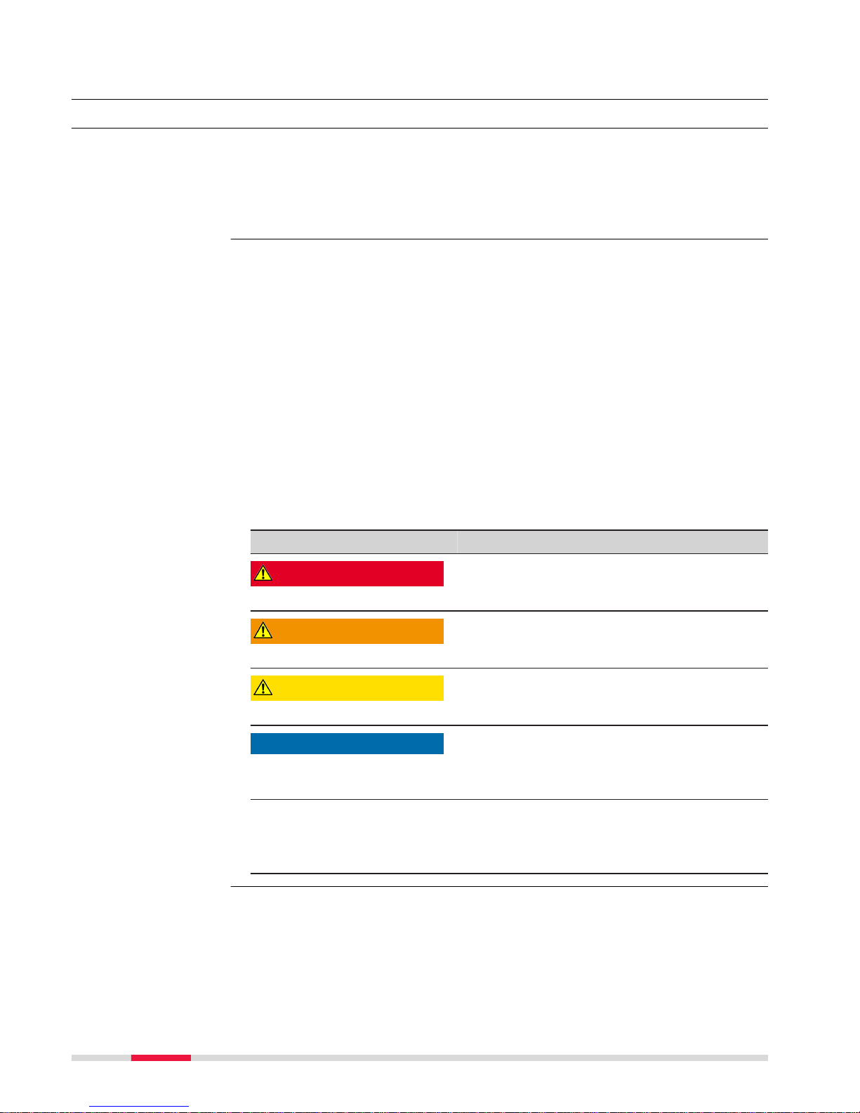
Art. No.:
123456
Equip. No.:
1234567
Serial No.:
1234567
Power:15V nominal / 2.5 A max.
Made in Switzerland
Manufactured: MM. YYYY
This device complies with part 15 of the FCC Rules.
Operation is subject to the following two conditions:
(1) This device may not cause harmful interference,
and (2) this device must accept any interference
received, including interference that may cause
undesired operation.
008466_002
This device comp li es w ith p ar t 15 of t he FC C Rul es. O pe rat io n is
subject to the following two conditions: (1) This device may not cause
harmful inter fe re nc e, a nd (2) t hi s dev ic e m us t ac c ep t any i nte r f er en ce
received, including interference that may cause undesired operation.
FCC-ID: RFD-CTR20
IC: 3177A-CTR2 0
Made in Switzerland, Manufactured: 20XX
Leica Geosystems AG, CH-9435 Heerbrugg
S.No. :1234567 Equip.No.:12345678
Art. N o . : 808038
Type:CTR20
008467_002
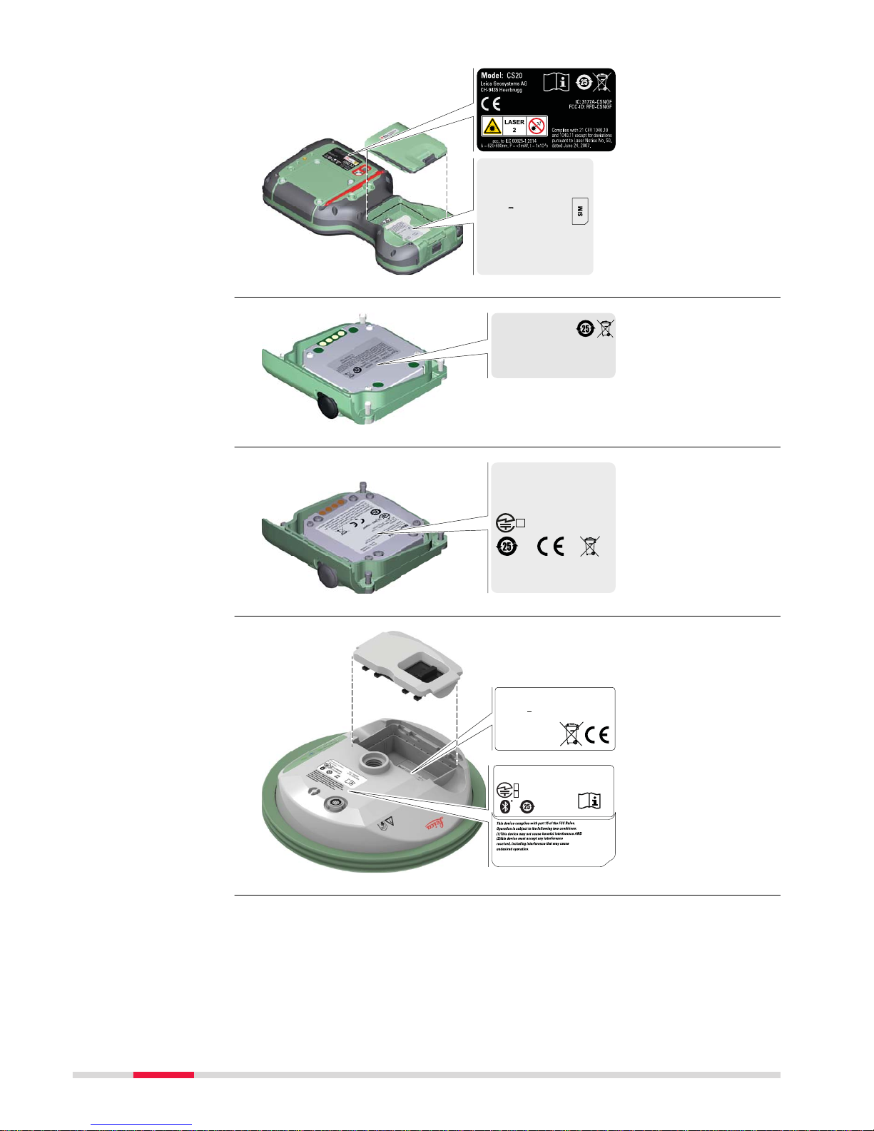
0014952_001
Model: CGR4
Equip.No.:12345678
Leica Geosystems AG, CH-9435 Heerbrugg
Made in Switzerland, Manufactured: 2017
Contains:
FCC ID: MRBSATEL - TA23
IC: 2422A - SATELTA23
S.No.: 1234568
Art.No.: 798498
R:
003 - 170097
This device complies with part 15 of the FCC Rules.
Operation is subject to the following two conditions:
(1) This device may not cause harmful interference, and
(2) this device must accept any interference received,
including interference that may cause undesired operation.
This device contains
a transmitter:
FCC: PVH0925
IC ID: 5325A-0925
R 202-SMA054
T D 12-0040 202
IP66
IP68
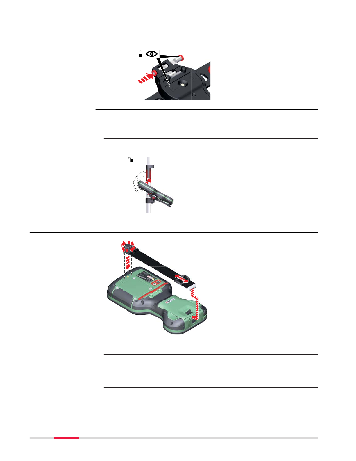
Model: GS07
Art.No.:
Equip. No.: 12345678 S.No.:
123456
Power: 7.4V --- nominal / 0.6 A max.
Leica Geosystems AG
CH-9435 Heerbrugg
Manufactured: 20XX
Made in Switzerland
869374
0016445_002
Labelling CS20
Labelling CTR20
Labelling CGR4
Labelling GS07
16 Safety Directions
Page 17

0008469_006
11WE
MH29443
This device complies with part 15 of the FCC Rules.
Operation is subject to the following two conditions:
(1) This device may not cause harmful interference, and
(2) this device must accept any interference received,
including interference that may cause undesired operation.
Type: GEB331
Li-Ion Battery
11.1 V / 2.8 Ah
15 A / 31.1 Wh
Leica Ge osystems AG, CH -9435 Heerbrug g
Art.No.: 799190
S.No.: XXXXX
Made in China
005044_002
005044
_002
Made in China
Type: GEB212
2ICR19/66
Art. No.: 772806
7.4V
/2.6 Ah
10A
19Wh
XXXXXXXX-XXXXXX
A/S:+82 31 620 6252
Leica Geosystems AG, CH-9435 Heerbrugg
Li-Ion Battery
5A/130 C
S. No.:10412
전지
Manufactured by Huizhou Longji Electronics Co., Ltd.
The wireless device is a radio transmitter and receiver. It is designed and manufac
tured not to exceed the emission limit for exposure to radio frequency (RF)
energy set by the OET Bulletin 65 Supplement C / Ministry of Health (Canada),
Safety Code 6. These limits are part of comprehensive guidelines and established permitted levels of RF energy for the general population. These guidelines are based on the safety standards previously set by international standard
bodies. These standards include a substantial safety margin designed to assure
the safety of all persons, regardless of age and health.
This device and its antenna must not be co-located or operating in conjunction
with any other antenna or transmitter.
This device has been shown to be capable of compliance for localised specific
absorption rate (SAR) for uncontrolled environment / general public exposure
limits specific in ANSI/IEEE C95.1-1992 and had been tested in accordance with
the measurement procedures specified in IEEE Std. 1528-2003.
WARNING
This Class (B) digital apparatus complies with Canadian ICES-003.
Cet ap
pareil numérique de la classe (B) est conforme à la norme NMB-003
du Canada.
Canada Compliance Statement
This de
vice complies with Industry Canada’s license-exempt RSSs. Operation
is subject to the following two conditions:
1. This device may not cause interference; and
2. This device must accept any interference, including interference that
may cause undesired operation of the device.
Canada Déclaration de Conformité
Le présent appareil est conforme aux CNR d’Industrie Canada applicables aux
appareils radio exempts de licence. L’exploitation est autorisée aux deux conditions suivantes:
1. l’appareil ne doit pas produire de brouillage;
2. l’appareil doit accepter tout brouillage radioélectrique subi, même si le
brouillage est susceptible d’en compromettre le fonctionnement.
Labelling GEB331
Labelling internal
batter
y GEB212
Exposure to radio frequen
cy (RF) signals
Safety Directions 17
Page 18

2 Description of the System
2.1 Overview
0016300_001
CTR20CGR4
CS20 CDMA
DISTO
CS20 3.75G
DISTO
CS20 3.75G
CS20 GS07
2.2 Terminology
CS is a collective term describing the various models of the multi-purpose field
co
ntroller which is used with GNSS and TS instruments.
Model CS20 CS20
3.75G
CS20
3.75G
DISTO
CS20
CDMA
DISTO
Touch screen
ü ü ü ü
Colour display
ü ü ü ü
Internal long-range TS communication radio
-
ü ü ü
Internal 3.75G modem -
ü ü ü
Internal CDMA modem - - -
ü
Internal battery
1
ü ü ü ü
DISTO - -
ü ü
SD card
ü ü ü ü
Bluetooth
ü ü ü ü
External long-range TS communica
tio
n radio
- As expansion pack CTR20
GNSS UHF RTK radio - As expansion pack CGR4
Wireless LAN 802.11b/g/n
ü ü ü ü
Windows EC 7
ü ü ü ü
Camera with flash
ü ü ü ü
Camera in DISTO - -
ü ü
1
removable
System components
CS general description
A
vailable models
18 Description of the System
Page 19

Radios for remote control (RCS) or real-time kinematic (RTK) GNSS are
available in the f
ollowing variations:
Type Description
CS20 Radio unavailable
CS20 with internal long-range
TS c
ommunication radio
Field controller with an integrated long-range
TS communication radio.
CS20 with expansion pack Field controller with an integrated long-range
TS communication radio. A high-performance
wireless data transfer device (CTR20) can be
attached.
2.3 System Concept
2.3.1 Software Concept
Software type Description
CS firmware This software includes:
(CS_xx.fw)
•
T
he multi- language-sp
ecific version of
Windows EC 7.
•
The necessary functionality of the instrument, including Leica Captivate.
•
The main applications and languages are
integrated into the firmware. Languages
cannot be deleted.
•
The software for the CGR4 UHF radio.
Software type Description
ME firmware This software includes:
(ME_xx.fw) - The firmware for the measurement engine.
☞
Uploading firmware can take some time. Ensure that the battery is at
leas
t 75% full before beginning the upload, and do not remove the
battery during the upload process.
CS available radios
Software
Software for the
GS07
So
ftware upload
Description of the System 19
Page 20

Software for Description
All CS models
The software is stored in the flash RAM of
the field c
ontroller.
Firmware update instructions
•
Download the most recent firmware file
from
https://myworld.leica-geosystems.com.
•
Copy the firmware file into the \SYSTEM
folder on the Leica SD card.
☞
Ensure that the Leica SD card is
inserted into the field controller
before starting the upload.
•
Star
t Leica Captivate. To open the
Update Software panel, select Settings
> Tools > Update software.
•
Select the firmware file to upload and
start the update process. When the
update process is finished, the new version of Leica Captivate is started.
GS07
The software is stored in the flash RAM of
the GS07.
ME firmware update instructions
•
Go t
o www.myworld.leica-geosys-
tems.com and log in.
•
Go to myProducts and select your prod-
uct.
☞
If your product is not in the list,
click Add Product.
•
Click the
Software tab and download
the software to your computer.
•
Unzip the file and store the required files
in the \SYSTEM directory of the data storage device.
•
Insert the data storage device into the
connected field controller an turn it on.
•
Captivate: Go to Settings\Tools\Update
software.
•
File to load: Select the firmware to
upload.
•
Click OK. The software is uploaded to
your product.
CGR4 The software is stored in the UHF radio mod-
ule in the CGR mo
dule.
20 Description of the System
Page 21

Software for Description
CGR UHF radio firmware update instruc-
tions
•
Download the mos
t recent CS20 firmware file from
https://myworld.leica-geosystems.com.
•
Copy the CS20 firmware file into the
\SYSTEM directory of the Leica SD card.
•
Connect the CGR radio to the CS field
controller and configure the CGR radio as
RTK device. Refer to the Leica Captivate
Technical Reference Manual.
•
Select the firmware file to upload and
start the update process. A message will
appear when the upload is complete.
2.3.2 Power Concept
Use the batteries, chargers and accessories recommended by Leica Geosystems
to ensur
e the correct functionality of the instrument.
Model Power supply
All CS models Internally by GEB331 battery, OR
Externally by GEV276 cable, OR
Externally by GEV219 cable
If an external power supply is connected and the internal
bat
tery is inserted, then the external power is used. The
internal battery is charged.
Please note: Charging functionality is not available for CS20
field controller.
CTR20, CGR4 Externally by the field controller.
Please note: Expansion pack support is not available for CS20
field controller.
GS07 Internally by GEB212 battery, OR
Externally by GEV219 cable
If an external power supply is connected and the internal
battery is inserted, then the external power is used.
2.3.3 Data Storage Concept
Data is stored on a memory device. The memory device can be an SD card, USB
stick o
r internal memory.
Device Description
SD card All field controllers have an SD card slot fitted as standard.
An SD card can b
e inserted and removed. Available capacity:
1 GB, 8 GB.
USB stick All field controllers have a USB port fitted as standard.
Internal
memory
All field controllers have an internal memory fitted as standard. Available capacity: 2 GB.
General
Power options
Description
Memory device
Description of the System 21
Page 22

☞
While other SD cards can be used, Leica Geosystems recommends to
onl
y use Leica SD cards and is not responsible for data loss or any
other error that can occur while using a non-Leica card.
Removing the SD card or USB stick while the field controller is turned on can
cause loss o
f data. Only remove the SD card or USB stick or unplug connecting
cables when the field controller is switched off.
Data can be transferred in various ways. Refer to "4.1.8 Connecting to a Perso
nal Computer".
SD cards can directly be used in an OMNI drive as supplied by Leica Geosystems. Other PC car
d drives can require an adaptor.
2.4 Container Contents
0014958_001
d
a
b
c
e
f
g
h
i
j
k
l
m
n
o
p
q
☞
Transfer data
☞
Container for GS
instrum
ent and
accessories 1/2
22 Description of the System
Page 23

a GHT63 clamp
b M
anuals and USB documentation card
c GEB212 or GEB331 batteries
d Antenna
e GAT18, GAT27 or GAT28 mobile antenna
f GAT21, GAT25 or GAT26 radio antenna
g Field controller with holder or CS35 tablet
h Tribrach
i Height hook
j USB stick
k Cables
l Antenna
m Stylus
n SD cards
o GAD34 arm 3 cm
p TNC QN-adapter
q Allen key and adjustment tool
0014961_001
a
b
c
i
d
e
h
f
g
j
j
a GHT36 base for telescopic rod
b Antenna arm
c GFU RTK modem
d GAD32 telescopic rod
e GAT1 or GAT2 radio antennas
f GEB212 or GEB331 batteries
g GRT146 or GRT247 carrier
h GAD33 arm
i GHT58 tripod bracket for GFU
j External battery
Container for GS
instrum
ent and acces-
sories 2/2
Description of the System 23
Page 24

0014955_001
a h
i
j
k
l
b
c
d
e
f
g
a Field controller with holder
b An
tenna
c CRP15, quick release adaptor for quick mounting and demounting the
GS18 to the pole without screwing
d GAT25, GAT26, GAT27 or GAT28 antenna
e Stylus
f GHT63 clamp
g USB stick
h GAT1 or GAT2 radio antennas
i Antenna arm
j microSD card including adapter or SD card
k Manual & USB documentation card
l GEB212 or GEB331 batteries
Container for GS
instrum
ent and
accessories
24 Description of the System
Page 25

2.5 CS Components
008471_001
a
b
c
e
f
d
g
h
a DISTO with camera
b
Scr
een
c Keyboard
d Connector cover
e Power socket
f SD card slot
g USB A host port
h LEMO port (USB and serial)
008472_001
a
b
c
h
e
f
d
g
i
a Hand strap
b
T
hread for screwing on hand
strap or utility hook
c Expansion cover
d Digital camera with flash
e Stylus
f Battery compartment
g SIM card slot under the bat-
tery
h Socket for fastening clip of
the hand strap
i Tether for the stylus
2.6 GS07 Components
0016301_001
a
b
c
d
e
a ON/OFF button
b
LEDs
c
LEMO port including USB port
d Antenna Reference Plane
(ARP)
e Battery compartment
Upside of CS20
Underside of CS20
GS07 components
Description of the System 25
Page 26

3 User Interface
3.1 Keyboard
008473_001
a
b
c
e
f
d
g
h
i
j
k
l
m
n
o
p
q
a Function keys F1 - F6
b Ar
row keys
c ESC
d OK
e Home
f Fn
g Numeric keys
h ± key
i ON/OFF
j CAPS Lock
k Cameras
l Favourites
m ENTER
n Function keys F7 - F12;
Backspace
o Alpha keys
p ENTER
q SPACE
Key Function
Function keys
F1-F6
Correspond to six softkeys that appear on
the bo
ttom of the screen when the screen is
activated.
Function keys
F7-F12
User definable keys to execute chosen commands or ac
cess chosen screens.
Alpha keys
To type letters.
Numeric keys To type numbers.
Caps Lock Switches between upper case and lower case
let
ters.
Backspace
Clears all entry at the beginning of user
input.
C
lears the last character during user input.
Esc
Leaves the current screen without storing
any change
s.
Fn
Switches between the first and second level
of f
unction keys.
Space
Enters a blank.
Enter Selects the highlighted line and leads to the
next log
ical menu/ dialog.
Starts the edit mode for editable fields.
Opens a selectable list.
Keyboard display
Keys
26 User Interface
Page 27

Key Function
ON/OFF If the field controller is already off: Turns the
field c
ontroller on when held for 2 s.
If the field controller is already on:
•
Tur
ns to Power Options menu when held
for 2 s.
•
Turns the field controller off when held
for 5 s.
Favourites
Opens the “Favourites” pop-up bubble within
Leica Captiva
te.
Home
Switches to the Windows EC7 Start Menu.
Cameras Access the cameras.
Arrow keys Move the focus on the screen.
OK Selects the highlighted line and leads to the
next log
ical menu/ dialog.
Starts the edit mode for editable fields.
Opens a selectable list.
Backspace
Deletes the job in the centre of the job carousel.
Key Function
+ Hold Fn while pressing .
Switch to Windows.
+ Hold Fn while pr
essing
.
Tak
e a screenshot of the current screen.
+ Hold Fn while pressing .
Increase the screen brightness.
+ Hold Fn while pr
essing
.
Decre
ase the screen brightness.
+ Hold Fn while pr
essing
.
Incre
ase the volume for acoustic warning signals, beeps and keypresses on the field controller.
+ Hold Fn while pr
essing
.
Decre
ase the volume for acoustic warning
signals, beeps and keypresses on the field
controller.
+ Hold Fn while pr
essing
.
Lock/unlo
ck the keyboard.
Key combinations
User Interface 27
Page 28

Key Function
+ Hold Fn while pr
essing
.
Lock/unlo
ck the touch screen.
+
Hold Fn while pr
essing
.
Tur
n the torch on/off.
+ Hold Fn while pr
essing
or .
Switch t
o the previous/next page.
3.2 Operating Principles
The user interface is operated either by the keyboard or by the touch screen
with supplied s
tylus. The workflow is the same for keyboard and touch screen
entry, the only difference lies in the way information is selected and entered.
Operation by keyboard
Information is selected and entered using the keys. Refer to "3.1 Keyboard" for
a detailed description of the keys on the keyboard and their function.
Operation by touch screen
Information is selected and entered on the screen using the supplied stylus.
Operation Description
To select an item Tap on the item.
To start the edit mode in editable
fields
T
ap on the editable field.
To highlight an item or parts of it for
editing
Drag the supplied stylus from the left
to the right.
To accept data entered into an editable field and exit the edit mode
Tap on the screen outside of the
editable field.
To open a context-sensitive menu Tap on the item and hold for 2 s.
3.3 LED Indicators on CS20
The field controller has Light Emitting Diode indicators. They indicate the basic
field controller status.
008513_001
a
bc
a Power LED
b Blue
tooth LED
c Long range TS LED - not avail-
able for CS20 field controller
Description of the LEDs
LED LED Status Status of Field Controller
Power LED off Power is off.
Keyboard and touch
screen
LED in
dicators
28 User Interface
Page 29

LED LED Status Status of Field Controller
green Power is okay.
flashing
green
P
ower is okay. The battery is being charged.
red Power is low. The remaining time for which
enough power is available depends on the
use of wireless modules, the temperature
and the age of the battery.
flashing red Power is low. The remaining time for which
enough power is available depends on the
use of wireless modules, the temperature
and the age of the battery. The battery is
being charged.
fast flashing
red
Power is very low. The battery must be
charged.
Bluetooth
LED
and
Long range
TS LED
green Bluetooth is not connected.
blue Bluetooth is connected.
3.4 LED Indicators on GS07
Description
The GS07 ins
trument has Light Emitting Diode indicators. They indicate the
basic instrument status.
Diagram
abc
0016443_001
a Tracking LED (TRK)
b Blue
tooth LED (BT)
c Power LED (PWR)
Description of the LEDs
IF the is THEN
TRK LED off No satellites are tracked.
flashing
green
Le
ss than four satellites are tracked, a posi-
tion is not yet available.
green Enough satellites are tracked to compute a
position.
red GS07 instrument is initialising.
BT LED green Bluetooth is in data mode and ready for con-
necting.
LED indicators
User Interface 29
Page 30

IF the is THEN
blue Bluetooth has connected.
flashing blue Data is being transferred.
GS07 PWR
LED
off Power is off.
green Power is 100% - 20%.
red Power is 20% - 5%.
flashing red Power is low (<5%). The remaining time for
which enough p
ower is available depends on
the type of survey, the temperature and the
age of the battery.
30 User Interface
Page 31

4 Operation
4.1 Equipment Setup
4.1.1 Setting up as a Post-Processing Base
The equipment setup described is used for static operations over markers.
The instrument can be programmed with the field controller before use which
can then be o
mitted from the setup.
•
T
he an
tenna is mounted directly using screw fitting. If using stub and
adapter, procedures can vary slightly.
•
When using the adapter and carrier, ensure that the antenna and the
adapter assembly slide down the full length of the carrier stub. An incorrectly mounted antenna will have a direct effect on the results.
If the instrument is left in the container during use in high temperatures, the
lid should be le
ft open. Refer to the User Manual for operating and storage
temperatures.
Use an external battery such as GEB371 to ensure operation for a full day.
002496_003
a
b
c
i
k
d
e
f
g
h
l
m
n
o
p
b
j
b
Use
Description
☞
☞
☞
Equipment setup
Operation 31
Page 32

a GS instrument
b (micr
o)SD card
c GEB212 battery
d GRT146 carrier
e Tribrach
f Height hook
g Tripod
h GHT61 hand strap
i CompactFlash card
j Utility hook
k CS20 field controller
l GEB331 battery
m CS10/CS15 field controller
n GEB212 battery
o CS35 tablet
p USB stick
1. Set up the tripod.
2. Mount and level the tribrach on the tripod.
3. Ensure that the tribrach is over the marker.
4. Place and lock the carrier in the tribrach.
5. Insert the data storage device and the batteries into the GS.
6. Screw the GS onto the carrier.
7. Check that the tribrach is still level.
8. Insert the data storage device and the battery into the field controller.
9.
Switch on the field controller and connect it to the instrument if necessary.
10. To hang the field controller on the tripod leg, use the hook on the
hand strap or use the utility hook. Refer to the User Manual of the
field controller.
11. Insert the height hook into the carrier.
12. Measure the antenna height using the height hook.
13. Press the ON/OFF button on the instrument for at least 2 s to switch
on the instrument.
Equipment setup
step-by-s
tep
32 Operation
Page 33

4.1.2 Fixing the Field Controller to a Holder and Pole
The GHT66 holder consists of the following components:
008545_001
a
b
c
f
d
e
g
h
i
GHT63 clamp
a Plastic sleeve
b P
ole clamp
c Clamp bolt
GHT66 holder
d Locking pin
e Top clip
f Mounting plate
g Bottom clip
h Tightening screw
i Mounting arm
☞
For an aluminium pole, fit the plastic sleeve to the pole clamp.
1. Insert the pole into the clamp hole.
2. Attach the holder to the clamp using the clamp bolt.
3. Adjust the angle and the height of the holder on the pole to a comfo
rtable position.
4. Tighten the clamp with the clamp bolt.
5. Before placing the CS field controller onto the mounting plate, ensure
that the locking pin is put into the unlocked position. To unlock the
locking pin, push the locking pin to the left.
008546_001
6. Hold the CS field controller above the holder and lower the end of
the CS field c
ontroller into the mounting plate.
7. Apply slight pressure in a downward direction and then lower the top
part of the CS field controller until the unit is clicked into the holder.
The guides of the mounting plate aid in this action.
7c
7a
7b
008547_001
Components of the
GHT66 holder
Fixing th
e field
controller and GHT66
to a pole step-bystep
Operation 33
Page 34
8. After the CS field controller is placed onto the mounting plate,
ensure tha
t the locking pin is put into the locked position. To lock
the locking pin, push the locking pin to the right.
008549_001
1. Unlock the locking pin by pushing the locking pin to the left of the
mounting pla
te.
2. Place your palm over the top of the field controller.
3. While in this position, lift the top of the field controller from the
holder.
2
3
1
008551_001
4.1.3 Fixing a Hand Strap to the CS
008501_001
2b
1
3
2a
☞
Turn over the field controller.
1. Take the end of the hand strap and clip it to the socket at the botto
m of the field controller.
2. Place the screw of the main hook into the thread at the top of the
field controller and fasten it.
3. Adjust the length of the hand strap.
Detaching the field
contr
oller from a pole
step-by-step
Fixing the hand strap
(GHT67) step-by-step
34 Operation
Page 35

4.1.4 Fixing the Utility Hook to the CS
008498_001
1b
1a
☞
If the hand strap is already attached to field controller, you need to
de
tach it b
efore you can fix the utility hook.
☞
Turn over the field controller.
1. Place the screw of the utility hook into the thread at the top of the
field controller and fasten it.
4.1.5 Replacing the Display Foil on the CS
On delivery, the display of the CS is covered by a foil to protect the display
agains
t s
cratches and dirt and to guarantee a trouble-free function of the
touchscreen in extreme and humid weather conditions. We strongly recommend to use this display foil and to replace it, if necessary.
•
Remov
e the old display foil.
•
Ensure that the display is free of dust and grease.
•
Use the provided microfibre cloth to clean the display.
•
Look for a dust free and dry atmosphere surrounding while fixing the display foil. The recommended conditions are:
Temperature: approx. 21°C
Humidity: < 55%
The display foil lies between two thin carrier foils. The display foil has a silvercolour
ed sticker to peel away the carrier foil from the actual display foil.
004510_001
1
2
3
4
Fixing the utility hook
(GHT68) s
tep-by-step
☞
Preparation
Fixing the display foil
step-by-s
tep
Operation 35
Page 36

1. Touch the yellow-coloured sticker with two fingers and pull it slowly
upwards. T
he carrier foil is peeling away.
☞
Do not peel the carrier foil more than 2 cm - 3 cm away.
2. Fix the adhesive underside of the display foil on the display edge.
Peel away the carrier foil slowly and smooth it out gently onto the
display.
3. Remove the additional layer foil which has a red-coloured sticker.
4. Potential air bubbles between display and display foil have to be
smoothed out using the included microfibre cloth.
☞
Do not use sharp objects!
5. In case of remaining dust or grease under the display foil or the need
to replace the display foil, lift it again with some adhesive tape.
4.1.6 Inserting and Removing a SIM Card
2b
3
4
8
9a
2a
9b
5s = OFF
1
7b
7a
6a
6b
5b
5a
008506_001
☞
Inserting/removing the SIM card while the CS20 is turned on can
re
sult in permanent damage to the card. Only insert/remove the SIM
card when the CS20 is switched off.
☞
The SIM card is inserted into a slot inside the battery compartment.
1. Switch off the field controller.
2. Push the slide fastener of the battery compartment in the direction
of the arrow with the open-lock symbol.
Remove the cover from the battery compartment.
3. Remove the battery from the battery compartment.
4. Bend up the flap that covers the SIM card holder.
5. Push the SIM card holder in the direction of the OPEN arrow and flip
it up.
Insert and remove a
SIM c
ard step-by-step
36 Operation
Page 37

6. Place the SIM card into the SIM card holder, the chip facing the connect
ors inside the slot - as shown beside the SIM card holder.
7. Press the SIM card holder down and push the SIM card holder in the
direction of the LOCK arrow to close.
8. Bend down the flap again and reinsert the battery.
9. Attach the cover of the battery compartment. Push the slide fastener
of the battery compartment in the direction of the arrow with the
closed-lock symbol.
4.1.7 Setting Up for Remote Control or RTK using an Expansion Pack
This section does only apply to the models CS20 3.75G, CS20 3.75G DISTO and
CS20 CD
MA DISTO.
☞
The CTR20 is not available in EU countries.
1b
1a
3
2b
2a
4
008507_001
☞
When the expansion cover or expansion pack are detached from the
field c
ontroller, the IP68 protection does not apply! Look for a dry and
dust free atmosphere when detaching the expansion cover or the
expansion pack.
1. Loosen the screws of the expansion cover and detach the cover from
the field controller.
2.
☞
Check the position of the contacts in the inner surface of
the field controller.
Attach the expansion pack to the field controller.
3. Tighten the screws of the expansion pack with the supplied allen
key.
4. Attach the antenna to the expansion pack.
☞
Using a rotating movement makes it easier to attach the
antenna, especially at low temperatures.
Attaching the extension pac
k step-by-
step
Operation 37
Page 38

4.1.8 Connecting to a Personal Computer
Windows Mobile Devic
e Center for PCs with Windows 7/Windows 8/
Windows 10 operating system is the synchronization software for Windows
mobile-based pocket PCs. WMDC enables a PC and a Windows mobile-based
pocket PC to communicate.
Leica USB drivers support Windows 7, Windows 8 (8.1) and Windows 10 operating sys
tems.
Cables
Leica USB drivers support:
Name Description
GEV223 USB data cable, 1.8 m, connects instrument to Mini-USB to
USB
GEV234 USB data cable, 1.65 m, connects CS to GS or CS to PC (USB)
GEV261 Y-cable, 1.8 m, connects instrument to PC – battery
☞
Skip the following steps if you have never installed Leica USB drivers
be
fore.
If older drivers were previously installed on the PC, follow the instructions to
uninstall the drivers prior the installation of the new drivers.
1. Connect your instrument to the PC via cable.
2. On your PC, select to Contr
ol Panel > Device Manager.
3. In Network Adapters, right-click on Remote NDIS based LGS….
4. Click on Uninstall.
5. Set Delete the driver… as checked. Press OK.
1. Start the PC.
Description
Uninstalling the
previous drivers
Ins
tall Leica USB
drivers
38 Operation
Page 39

2. Run the Set
up_Leica_USB_XXbit.exe to install the drivers necessary
for Leica devices. Depending on the version (32bit or 64bit) of the
operating system on your PC, you have to select between the three
setup files following:
•
Setup_Leica_USB_32bit.exe
•
Setup_Leica_USB_64bit.exe
•
Setup_Leica_USB_64bit_itanium.exe
☞
To check the version of your operating system, go to Control Panel > System > System type.
☞
The setup requires administrative privileges.
☞
The setup has to be run only once for all Leica devices.
3. The Welcome to InstallShield Wizard for Leica GS, TS/TM/MS,
CS and GR USB drivers window appears.
☞
Ensure that all Leica devices are disconnected from your PC
before you continue!
4. Next>.
5. The Ready to Install the Program window appears.
6. Install. The drivers will be installed on your PC.
Operation 39
Page 40

7. The InstallShield Wizard Completed window appears.
8.
Click Finish to exit the wizard.
1. Start the PC.
2. Plug the cable into the instrument.
3. Turn on the instrument.
4. Plug the cable into the USB port of the PC.
5. Press the Windows Start button at the bottom left corner of the
scr
een.
6. Type the IP address of the device into the search field.
•
\\192.168.254.1\ f
or field controller
•
\\192.168.254.3\ for other instruments
7. Press Enter.
A file browser opens. You can now browse within the folders on the
instrument.
4.1.9 Enabling WLAN in Windows EC7
☞
By default, the WLAN module is disabled to save battery power.
1. In order to minimise Leica Cap
tivate, press Fn and Home.
2. Select Start\Settings\Network and Dial-Up Connections.
3. In the Network Connections window:
Tap the TIWLNAPI1 icon and select File\Enable.
OR
Hold the stylus on the TIWLNAPI1 icon. Select Enable from the
context menu.
4.2 Batteries
4.2.1 Operating Principles
•
T
he ba
ttery must be charged before using it for the first time because it is
delivered with an energy content as low as possible.
•
The permissible temperature range for charging is from 0 °C to +40 °C/
+32 °F to +104 °F. For optimal charging, we recommend charging the batteries at a low ambient temperature of +10 °C to +20 °C/+50 °F to +68 °F
if possible.
•
It is normal for the battery to become warm during charging. Using the
chargers recommended by Leica Geosystems, it is not possible to charge
the battery once the temperature is too high.
•
For new batteries or batteries that have been stored for a long time
(> three months), it is effectual to make only one charge/discharge cycle.
•
For Li-Ion batteries, a single discharging and charging cycle is sufficient. We
recommend carrying out the process when the battery capacity indicated
on the charger or on a Leica Geosystems product deviates significantly
from the actual battery capacity available.
Connect to PC via USB
cable s
tep-by-step
Enabling WLAN stepby-step
Firs
t-time use/
charging batteries
40 Operation
Page 41

•
The ba
tteries can be operated from -30°C to +60°C/-22°F to +140°F.
•
Low operating temperatures reduce the capacity that can be drawn; high
operating temperatures reduce the service life of the battery.
4.2.2 Changing the Battery
2
3
4a
4b
5a
1
5b
008509_001
☞
Turn over the field controller.
1. Push the slide fastener in the direction of the arrow with the openlock sy
mbol.
2. Remove the cover from the battery compartment.
☞
Ensure that no water enters the battery compartment.
IP68 applies only with the battery compartment closed.
3. Pull the battery from the battery compartment.
4. Place the battery into the battery compartment with the arrow facing
to the top.
5. Attach the cover of the battery compartment. Push the slide fastener
of the battery compartment in the direction of the arrow with the
closed-lock symbol.
Operation/discharging
Insert and remove the
batter
y step-by-step
Operation 41
Page 42

0016444_001
2
3
4a
4b
6a
6c
8
6b
1. Turn GS07 over to gain access to the battery compartment.
2. Open the battery compartment by pushing the slide fastener in the
direc
tion of the arrow with the open-lock symbol.
3. Pull out the battery housing. The battery is attached to the housing.
4. Hold the battery housing and pull the battery from the battery housing.
5. A polarity of the battery is displayed inside the battery housing. This
is a visual aid to assist in placing the battery correctly.
6. Place the battery onto the battery housing, ensuring that the contacts are facing outward. Click the battery into position.
7. Close the battery compartment by pushing the slide fastener in the
direction of the arrow with the close-lock symbol.
4.2.3 Charging the Battery
☞
Please note: Charging functionality is not available for CS20 field controller (
823 164).
1b
GEV276
GEV219
1b
1a
1a
008512_001
Insert and remove the
batter
y on the GS07
step-by-step
Charge the battery
inside the CS20 s
tep-
by-step
42 Operation
Page 43

1. Connect the GEV276 power adapter or GEV219 with the field controller
.
2. The power LED on the CS field controller switches on. While charging, the power LED flashes. When the field controller’s battery is fully
charged the Power LED is green.
☞
Refer to LED indicators for detailed information about the
power LED.
To charge the batteries for GS07, use the Leica Geosystems chargers GKL311
or G
KL341. Refer to the GKL311 or GKL341 User Manual for further informa-
tion.
4.3 Power Functions
Press and hold power key ( ) for 2 s.
☞
The field controller must have a power supply.
Press and hold power key ( ) for 5 s.
☞
The field controller must be on.
Press and hold power key ( ) for 2 s to open Pow
er Down Options menu.
☞
The field controller must be on.
Option Description
Power down and turn off To turn the field controller off.
Put into stand-by To put the field controller into stand-by
mode.
R
eset hardware Perform one of the following options:
•
Restart hardwareThe device powers
down and restarts.
•
Reset Windows EC7The device powers
down and restarts. Any Bluetooth pairings are deleted.
•
Reset Leica CaptivateThe device powers down and restarts. All working styles,
dial-up lists and server lists are deleted.
Jobs, code lists, coordinate systems etc.
are not deleted.
•
Reset Windows EC7 and Leica CaptivateThe device powers down and
restarts. Bluetooth pairings, working
styles, dial-up lists and server lists are
deleted.
To turn on the instrument press and hold the ON/OFF button for 2 s.
To turn off the instrument press and hold the ON/OFF button for 2 s.
Charge battery for
GS07
T
urning field
controller on
Turning field
controller off
Menu “Power Down
Options”
Turn on GS07
Turn off GS07
Operation 43
Page 44

4.4 Working with the Memory Device
4.4.1 Working with the SD Card
•
Keep the car
d dry.
•
Use it only within the specified temperature range.
•
Do not bend the card.
•
Protect the card from direct impacts.
Failure to follow these instructions could result in data loss and/or permanent
damage to the car
d.
3
2b
2a
1b
1a
008502_001
☞
The SD card can be inserted into a slot behind the connector cover.
1. Push the slide fastener of the connector cover in the direction of the
arr
ow with the open-lock symbol. Open the connector cover.
2. Hold the card with the contacts facing the slot. Slide the card firmly
into the slot until it clicks into position.
☞
Do not force the card into the slot.
3. To release the card from the slot, gently press the top of the card.
The card pops out and you can remove it from the slot.
4. Close the connector cover. Push the slide fastener of the battery
compartment in the direction of the arrow with the closed-lock symbol.
☞
☞
Insert and remove the
SD car
d step-by-step
44 Operation
Page 45

4.4.2 Working with a USB Memory Stick
2
1b
1a
008504_001
☞
The USB stick can be inserted into a slot behind the connector cover.
1. Push the slide fastener of the connector cover in the direction of the
arrow with the open-lock symbol. Open the connector cover.
2. Insert the USB stick into the USB A host port.
4.5 Using the Digital Camera
The field controller is equipped with a digital camera and a flash light, both
located at the underside. Mounting a hand strap or pole holder plate does not
limit the camera view.
You can start the camera application from within Leica Captivate.
☞
To be able to start the camera application, Leica Captivate has to be
op
en.
1. Press the Camera key
.
The s
creen Capture Image is displayed.
2. Aim the camera to the desired target.
3. Check the view at the display.
4. Press the OK key or click Capture to take a picture.
The picture is displayed in the Image Viewer.
☞
Capture changes to Store.
5. Press OK again or click Store to store the picture.
An info screen is displayed where you can choose to save the picture
with a link to a point, line or area.
6. Press F2 or F3 to store the picture with a link. Follow the instructions
on the screen.
Press F4 to store the picture without a link.
Press F6 to return to the Image Viewer without storing the picture.
After storing the picture, the Capture Image screen is displayed
again.
Insert a USB stick
step-by-s
tep
Overview
Taking a picture stepby-step
Op
eration 45
Page 46

4.6 Using the Camera Flash Light as Torch
You can use the flash light of the camera as torch.
To pu
t the flash light on/off, hold
and press .
Using the flash light
as tor
ch
46 Operation
Page 47

5 Care and Transport
5.1 Transport
Never carry the product loose in a road vehicle, as it can be affected by shock
and vibr
ation. Always carry the product in its container and secure it.
For products for which no container is available use the original packaging or
its equivalent.
When transporting the product by rail, air or sea, always use the complete original Leica Geosys
tems packaging, container and cardboard box, or its equiva-
lent, to protect against shock and vibration.
When transporting or shipping batteries, the person responsible for the product mus
t ensure that the applicable national and international rules and regulations are observed. Before transportation or shipping, contact your local passenger or freight transport company.
5.2 Storage
Respect the temperature limits when storing the equipment, particularly in
summer if the equipmen
t is inside a vehicle. Refer to "6 Technical Data" for
information about temperature limits.
•
R
e
fer to "6 Technical Data" for information about storage temperature
range.
•
Remove batteries from the product and the charger before storing.
•
After storage recharge batteries before using.
•
Protect batteries from damp and wetness. Wet or damp batteries must be
dried before storing or use.
•
A storage temperature range of 0 °C to +30 °C / +32 °F to +86 °F in a dry
environment is recommended to minimize self-discharging of the battery.
•
At the recommended storage temperature range, batteries containing a
40% to 50% charge can be stored for up to one year. After this storage
period the batteries must be recharged.
5.3 Cleaning and Drying
•
Use o
nly a clean, soft, lint-free cloth for cleaning. If necessary, moisten the
cloth with water or pure alcohol. Do not use other liquids; these may
attack the polymer components.
Dry the product, the transport container, the foam inserts and the accessories
at a t
emperature not greater than 40 °C/104 °F and clean them. Remove the
battery cover and dry the battery compartment. Do not repack until everything
is dry. Always close the transport container when using in the field.
Transport in a road
vehicle
Shipping
Shipping, transp
ort of
batteries
Product
Li-Ion batteries
Product and
accesso
ries
Damp products
Care and Transport 47
Page 48
Keep plugs clean and dry. Blow away any dirt lodged in the plugs of the connecting cable
s.
Wet connectors must be dry before attaching the dust cap.
008590_001
Cables and plugs
Connectors with dust
caps
DIS
TO window
48 Care and Transport
Page 49

6 Technical Data
6.1 CS20
Polymer housing with optional integrated battery and radio modem.
Type Description
Display 5", WVGA (800 x 480 pixels),
graphics capable L
CD, illumination, touch
screen, colour
Keyboard 67 keys including 12 function keys
Touch technology Resistive
Sound Integrated sealed speaker and microphone
Digital camera Resolution: 2592 x 1944 pixels, 5 MP, fixed
focus lens, image capture: JPEG, flash
DISTO Range: 150 m
Accuracy: ±1 mm + 0.2 mm/m
Resolution of view finder camera:
1600 x 1200 pixels, 2 MP
49 mm
284 mm
150 mm
008595_001
Type Weight [kg]/[lbs]
CS20 1.095/2.414
CS20 3.75G 1.175/2.590
CS20 3.75G/CDMA DISTO 1.215/2.678
Data can be stored on the SD card, USB stick or in the internal memory.
Design
Control unit
Dimensions
Weight
Memory devices
Technical Data 49
Page 50

Type Consump-
tion [A]
Ex
ternal supply voltage
CS20 2.5 Nominal voltage: 15 V DC (
)
Voltage r
ange: 10.5 V DC to 18.0 V DC
Minimum voltage for charging: 14 V DC (
)
Type Battery Voltage Capacity Operating time,
typical*
CS20 Li-I
on 11.1 V GEB331:
2.8 Ah
8 h
* Operating time depends on use of wireless communication devices.
Temperature
Type Operating temperature
[°C]
Storage temperature
[°C]
CS20 -30 to +60 -40 to +80
GEB331 -30 to +60 -40 to +70
Protection against water, dust and sand
Type Protection
CS20 IP68 (IEC60529)
Dust tig
ht
Protected against continuous immersion in water (tested for
2 hours in 1.40 m depth).
☞
CS20 is in compliance with IP68 only when expansion cover, connector cover and battery cover are
closed.
GEB331 IP54 (IEC 60529)
Dust protected
Protection against splashing water from any direction
Humidity
Type Protection
CS20 Up to 95 %
The e
ffects of condensation are to be effectively counterac-
ted by periodically drying out CS20.
GEB331 For indoor use only
Type RS232 USB Host USB
Client
B
lue-
tooth
WLAN
CS20 LEMO port USB2.0
Host (A)
LEMO USB
client
(highspeed)
Class 1 802.11b/g
/n
The default values are:
Pow
er
Internal battery
Environmental
specific
ations
Interfaces
Data format for
RS232
50 T
echnical Data
Page 51

Baud rate: 115200 Data bits: 8
Parity: None Stop bits: 1
Terminator: CR/LF
Type 8 pin LEMO-1 USB2.0 Host
(A)
LEMO USB client
(high-speed)
CS20 F
or power and/or
communication
For communication
6.2 GS07
6.2.1 Tracking Characteristics
Multi-frequency
☞
Depending on the satellite systems and signals configured, a maximum number of 320 channels is allo
cated.
System Signal
GPS L1, L2, L2C, L5
GLONASS L1, L2, L3*
Galileo E1, E5a, E5b, AltBOC, E6*
BeiDou B1, B2, B3*
QZSS L1 C/A, L2C, L5
SBAS
(WAAS, EGNOS, MSAS,
GAGAN)
L-band
* Believe to comply, but subject to availability of BeiDou Inter
face Control
Document and Galileo commercial service definition.
Carrier phase and code measurements on L1, L2 and L5 (GPS) are fully independent with AS o
n or off.
6.2.2 Accuracy
Accuracy is dependent upon various factors including the number of satellites
tr
ack
ed, c
onstellation geometry, observation time, ephemeris accuracy, iono-
spheric disturbance, multipath and resolved ambiguities.
The following accuracies, given as root mean square, are based on measurements processed using LGO and on real-time measurements.
The use of multiple GNSS systems can increase accuracy by up to 30% relative
to GPS only.
The baseline precision of a differential code solution for static and kinematic
surveys is 25 cm.
Ports
Satellite reception
Instrument channels
Supported signals
☞
☞
Differential code
Technical Data 51
Page 52

The measurement of accuracy is compliant with ISO 17123-8.
Type Horizontal Vertical
Static and rapid static 5 mm + 0.5 ppm 10 mm + 0.5 ppm
Kinematic
10 mm + 1 ppm 20 mm + 1 ppm
Static with long observations 3 mm + 0.5 ppm 6 mm + 0.5 ppm
Type Horizontal Vertical
Single Baseline (<30 km) 10
mm + 1 ppm
20 mm + 1 ppm
Network RTK 10
mm + 0.5 ppm
20 mm + 0.5 ppm
6.2.3 Technical Data
Type Height Diameter
GS07 0.071 m 0.186 m
8 pin LEMO-1
5/8" Whitworth
0.8 kg including internal battery
Type Description
Power consumption 2.0 W typically
External supply voltage Nominal 12 V DC (
), voltage range
10.5 V‑28 V
Type Battery Voltage Capacity
Operating time, typically
*
GEB212 Li-Ion 7.4 V 2.6 Ah 7 h
* The given operating times are valid for
•
one full
y charged GEB212 battery.
•
25°C. Operating times will be shorter when working in cold
weather.
Type GS07
Voltage Current Frequency
GPS L1 1575.42 MHz
ü
GPS L2 1227.60 MHz
ü
GPS L5 1176.45 MHz
ü
☞
Differential phase in
post-pr
ocessing
Differential phase in
real-time
Dim
ensions
Connector
Mounting
Weight
Power
Battery internal
Electrical data
52 Technical Data
Page 53

Type GS07
GLONASS L1 1602.5625-1611.5 MHz
ü
GLONASS L2 1246.4375-1254.3 MHz
ü
Galileo E1 1575.42 MHz
ü
Galileo E5a 1176.45 MHz
ü
Galileo E5b 1207.14 MHz
ü
Galileo AltBOC 1191.795 MHz
ü
BeiDou B1 1561.098 MHz
ü
BeiDou B2 1207.14 MHz
ü
Gain Typically 37 dBi
Noise Figure Typically < 3 dBi
Temperature
Operating temperature
[°C]
Storage temperature
[°C]
-40 to +65 -40 to +80
Bluetooth: -30 to +65
Protection against water, dust and sand
Protection
IP66 & IP68 (IEC 60529)
Dust-tight
Protected against water jets
Protected against continuous immersion in water
Te
sted for 2 h in 1.40 m depth
Humidity
Protection
Up to 95 %
The effects of condensation are to be effectively counteracted by periodically
drying ou
t the antenna.
6.3 Conformity to National Regulations
6.3.1 Products without Radio
For products without radio transmitter or receiver:
•
FC
C Part 15 (applicable in US)
•
Her
eby, Leica Geosystems AG declares that the product/s
is/are in compliance with the essential requirements and
other relevant provisions of the applicable European Directives.
The full text of the EU declaration of conformity is available
at the following Internet address:
http://www.leica-geosystems.com/ce.
Environmental
specific
ations
Conformity to
nat
ional regulations
Technical Data 53
Page 54

6.3.2 CS20
•
F
C
C Part 15, 22 and 24 (applicable in US)
•
Hereby, Leica Geosystems AG declares that the radio equipment type
CS20 is in compliance with Directive 2014/53/EU and other applicable
European Directives.
The full text of the EU declaration of conformity is available at the following Internet address: http://www.leica-geosystems.com/ce.
Class 1 equipment according to European Directive 2014/53/EU
(RED) can be plac
ed on the market and be put into service with-
out restrictions in any EEA member state.
•
The c
onformity for countries with other national regulations not covered
by the FCC part 15, 22 and 24 or European Directive 2014/53/EU has to
be approved prior to use and operation.
Type Frequency band [MHz]
CS20, Bluetooth 2402 - 2480
CS20, RCS 2402 - 2480
CS20, GSM (2G)/UMTS (3G) UMTS 800 / 850 / 900 / 1900 / 2100
GSM 850 / 900 / 1800 / 1900
HSPA Download: 7.2 Mbit/s
HSP
A Upload: 5.76 Mbit/s
CS20, WLAN 2400 - 2484
CS20,3.75G GSM/UMTS/
CDMA
Quad-Band GSM & Penta-Band UMTS & TriBand CDMA 800 / 1900
CTR20 2402 - 2480MHz
Type Output power [mW]
CS20, Bluetooth 10
CS20 < 20
CS20, GSM (2G)/UMTS (3G) EGSM850/900 2000
CS20, GSM (2G)/UMTS (3G) GSM1800/1900 1000
CS20, GSM (2G)/UMTS (3G) UMTS2100 250
CS20, GSM (2G)/UMTS (3G) EDGE850/900 500
CS20, GSM (2G)/UMTS (3G) EDGE1800/1900 400
CS20, WLAN (802.11b) - 11 Mbit/s 100
CS20, WLAN (802.11g) - 54 Mbit/s 80
CS20, WLAN (802.11n) - 65 Mbit/s 80
CS20, CDMA BC0 & BC10 (800)/BC1 (1900) 250
Type Antenna Gain
[dBi]
Connector Frequency
band
[M
Hz]
CS20,
Bluetooth
Integrated
antenna
2 - 2400-2480
Conformity to
nat
ional regulations
Frequency band
Output power
Antenna
54 Technical Data
Page 55

Type Antenna Gain
[dBi]
Connector Frequency
band
[M
Hz]
CS20, RCS Integrated
antenna
1 - 2400-2480
CS20,
GSM (2G)/
UMTS (3G)
Integrated
antenna
- - -
CS20, WLAN Integrated
antenna
1 - 2400-2480
CS20, GSM/
UMTS/CDMA
Integrated
antenna
0 max. @
800 / 850 /
900
- -
3 max. @
1800 /
1900 / 2100
- -
6.3.3 GS07, CTR20
•
F
C
C Part 15 (applicable in US)
•
Hereby, Leica Geosystems AG declares that the radio equipment type
GS07/CTR20 is in compliance with Directive 2014/53/EU and other applicable European Directives.
The full text of the EU declaration of conformity is available at the following Internet address: http://www.leica-geosystems.com/ce.
Class 1 equipment according to European Directive 2014/53/EU
(RED) can be plac
ed on the market and be put into service with-
out restrictions in any EEA member state.
•
The c
onformity for countries with other national regulations not covered
by the FCC part 15 or European Directive 2014/53/EU has to be approved
prior to use and operation.
Type Frequency band [MHz]
CTR20 2402 - 2480MHz
GS07, GNSS 1227.60
1575.42
1246.4375 - 1254.3
1602.4375 - 1611.5
GS07, Bluetooth 2402 - 2480
Type Output power [mW]
CTR20 < 100 mW (e. i. r. p.)
GS07, GNSS Receive only
GS07, Bluetooth 5 (Class 1)
Conformity to
nat
ional regulations
Frequency band
Output power
Technical Data 55
Page 56

Type Antenna Gain
[dBi]
Connector Frequency
band
[M
Hz]
CTR20 l/2 antenna 2 max. SMB
(internal)
-
GS07, GNSS Internal GNSS
antenna element (receive
only)
- - -
GS07,
Bluetooth
Internal
Microstrip
antenna
1.0 dBi - -
6.3.4 CGR4
•
F
C
C Part 15 (applicable in US)
•
Hereby, Leica Geosystems AG declares that the radio equipment type
CGR4 is in compliance with Directive 2014/53/EU and other applicable
European Directives.
The full text of the EU declaration of conformity is available at the following Internet address: http://www.leica-geosystems.com/ce.
•
This Class 2 equipment may be operated in: AT, BE, BG, CA, CH, CY, CZ,
DE, DK, EE, ES, FI, FR, GB, GR, HU, IE, IS, IT, LT, LU, LV, MT, NL, NO, PL, PT,
RU, RO, SE, SI, SK, US.
Class 2 equipment according to European Directive 2014/53/EU
(RED) fo
r which following EEA Member States apply restrictions
on the placing on the market or on the putting into service or
require authorisation for use:
•
France
•
Italy
•
Norway (if used in the geographical area within a radius of
20 km from the centre of Ny-Ålesund)
•
The conformity for countries with other national regulations not covered
by the FCC part 15 or European Directive 2014/53/EU has to be approved
prior to use and operation.
403 - 473 MHz
Receive only radio
Type Gain Connector
l/2 antenna 0 dBi maximal SM
B (internal)
Antenna
Conformity to
nat
ional regulations
Frequency band
Output power
Antenna
56 Technical Data
Page 57

7 Software Licence Agreement
This product contains software that is preinstalled on the product, or that is
supplied t
o you on a data carrier medium, or that can be downloaded by you
online according to prior authorisation from Leica Geosystems. Such software is
protected by copyright and other laws and its use is defined and regulated by
the Leica Geosystems Software Licence Agreement, which covers aspects such
as, but not limited to, Scope of the Licence, Warranty, Intellectual Property
Rights, Limitation of Liability, Exclusion of other Assurances, Governing Law
and Place of Jurisdiction. Please make sure, that at any time you fully comply
with the terms and conditions of the Leica Geosystems Software Licence
Agreement.
Such agreement is provided together with all products and can also be referred
to and downloaded at the Leica Geosystems home page at
http://leica-geosystems.com/about-us/compliance-standards/legal-documents
or collected from your Leica Geosystems distributor.
You must not install or use the software unless you have read and accepted
the terms and conditions of the Leica Geosystems Software Licence Agreement. Installation or use of the software or any part thereof, is deemed to be
an acceptance of all the terms and conditions of such Licence Agreement. If
you do not agree to all or some of the terms of such Licence Agreement, you
must not download, install or use the software and you must return the
unused software together with its accompanying documentation and the purchase receipt to the distributor from whom you purchased the product within
ten (10) days of purchase to obtain a full refund of the purchase price.
The software on the product may contain copyright-protected software that is
licenc
ed under various open source licences.
Copies of the corresponding licences
•
are provided together with the product (for example in the About panel of
the software)
•
can be downloaded on
http://opensource.leica-geosystems.com
If foreseen in the corresponding open source licence, you may obtain the corresponding source code and other related data on
http://opensource.leica-geosystems.com.
Contact
opensource@leica-geosystems.com in case you need additional information.
Software Licence
Agreem
ent
Open Source
information
Software Licence Agreement 57
Page 58

Appendix A Pin Assignments and Sockets
A.1 CS20
Some applications require knowledge of the pin assignments for the instrument p
orts.
In this chapter, the pin assignments and sockets for the instrument ports are
explained.
008379_001
ab
a LEMO port (USB and serial)
b USB A Host port
1
7
6
8
5
4
3
2
PIN_001
Pin Signal
Name
Function Direction
1 USB_D+ USB data line In or out
2 USB_D- USB data line In or out
3 GND Signal ground 4 RxD RS232, receive data In
5 TxD RS232, transmit data Out
6 ID Identification pin In or out
7 PWR Power input, 10.5 V-18 V In
8 GPIO RS232, general purpose signal In or out
A.2 GS07
Some applications require knowledge of the pin assignments for the instrument ports.
In this chapter, the pin assignments and sockets for the instrument ports are
explained.
Description
Ports at the instrumen
t bottom panel -
LEMO connector
Pin assignments for
8 pin LEM
O-1
Description
58 Pin Assignments and Sockets
Page 59

0016302_001
a
a Lemo port (USB and serial)
1
7
6
8
5
4
3
2
PIN_001
Pin Signal Name Function Direction
1 USB_D+ USB data line In or out
2 USB_D− USB data line In or out
3 GND Signal ground 4 RxD RS232, receive data In
5 TxD RS232, transmit data Out
6 NC Not connected 7 PWR Power input, 10.5 V–28 V In
8 AUX_ON RS232, manual PWR switch In
Ports at the instrumen
t underside
Pin assignments for
8 pin LEM
O-1
Pin Assignments and Sockets 59
Page 60

Leica Geosystems AG
Heinrich-Wild-Strasse
CH-9435 Heerbrugg
Switzerland
Phone +41 71 727 31 31
www.leica-geosystems.com
870196-1.0.2en
Original text (870196-1.0.2en)
Printed in Switzerland
© 2018 Leica Geosystems AG, Heerbrugg, Switzerland
 Loading...