

Page 1

Leica Detection DD Series
cators & Accessories
Lo
User Manual
Version 1.0
English
Page 2
Introduction
Purchase
Product identification
Trademarks
Validity of this
manual
Available
cumentation
do
Congratulations on the purchase of a Leica Detection product.
This manual contains important safety directions as well as instructions for setting up the p
information.
Read carefully through the User Manual before you switch on the product.
The model and serial number of your product are indicated on the type plate.
lways refer to this information when you need to contact your agency or
A
Leica Geosystems authorised service centre.
•
Bluetooth
All other trademarks are the property of their respective owners.
This manual applies to the Leica Detection DD series locators, DA series trans-
ters and Detection accessories. Differences between the models are marked
mit
and described.
Name Description/Format
Leica DD220/
D230 Series
D
Locators &
Accessories
Quick Guide
Leica DD220/
DD230 Series
Locators &
Accessories
User Manual
roduct and operating it. Refer to "1 Safety Directions" for further
®
is a registered trademark of Bluetooth SIG, Inc.
Provides an overview of the product together with
technical data and safety directions. Intended as a
quick reference field guide.
All instructions required in order to operate the
product to a basic level are contained in the User
Manual. Provides an overview of the product
together with technical data and safety directions.
ü ü
ü
Refer to the following resources for all Leica DD220/DD230
cumentation/software:
do
•
the Leica USB do
•
https://myworld.leica-geosystems.com
myWorld@Leica Geosystems (h
a wide range of services, information and training material.
With direct access to myWorld, you are able to access all relevant services
whenever it is convenient for you.
Service Description
myProducts Add all products that you and your company own
cumentation card
ttps://myworld.leica-geosystems.com) offers
and explo
detailed information on your products and update
your products with the latest software and keep upto-date with the latest documentation.
re your world of Leica Geosystems: View
2
Page 3

Service Description
myService View the current service status and full service his-
ory of your products in Leica Geosystems service
t
centres. Access detailed information on the services
performed and download your latest calibration certificates and service reports.
mySupport Create new support requests for your products that
will be answered by your local Leica Geosystems
Support Team. View the complete history of your
support requests and view detailed information on
each request in case you want to refer to previous
support requests.
myTraining Enhance your product knowledge with Leica Geosys-
tems Campus - Information, Knowledge, Training.
Study the latest online training material on your
products and register for seminars or courses in your
country.
myTrustedServices Add your subscriptions and manage users for Leica
Geosystems Trusted Services, the secure software
services, that assist you to optimise your workflow
and increase your efficiency.
3
Page 4

Table of Contents
1 Safety Directions 6
1.1 General 6
1.2 Definition of Use 6
1.3 Limits of Use 7
1.4 Responsibilities 7
1.5 Hazards of Use 8
1.5.1 General 8
1.5.2 Using the Product with a Signal Transmitter 12
1.6 Electromagnetic Compatibility EMC 13
1.7 FCC Statement, Applicable in U.S. 14
2 Description of the System 17
2.1 System Information 17
2.2 System Components 17
2.3 Locator Components 18
2.4 Signal Transmitter Components 18
2.5 Li-Ion Battery Pack 18
3 Operation of the Locator 20
3.1 Keyboard 20
3.2 Turning On / Turning Off 20
3.3 Display Screens 20
3.3.1 The Customisation Screens 20
3.3.2 The Locate Screen 22
3.3.3 The Depth Estimation Screens 23
3.4 Locator Menu 26
3.4.1 Access and Navigation 26
3.4.2 Menu Options 27
3.5 Search Modes 30
4 Operation of the Transmitter 34
4.1 Keyboard 34
4.2 Turning On / Turning Off 34
5 Applications 35
5.1 How to Pinpoint a Utility 35
5.2 How to Trace a Utility 36
5.3 How to Conduct a Sweep Search 36
5.4 Using the Transmitter in Induction Mode 38
5.4.1 General Information 38
5.4.2 Induction Mode: Nulling-Out Method 39
5.4.3 Induction Mode: Parallel-Sweep Method 40
5.4.4 Induction Mode: Radial-Sweep Method 41
5.5 Using the Transmitter in Connection Mode 42
5.5.1 General Information 42
5.5.2 Direct Connection Mode 43
5.5.3 Connection Mode: 131 kHZ Cable-Wrap Technique 44
5.6 How to Use the Trace Rod 46
5.6.1 General Information 46
5.6.2 Locating a Utility Using the Trace Rod 47
5.7 How to Use the Transmitter Clamps 50
5.7.1 General Information 50
5.7.2 Using a Transmitter Clamp to connect to Cable Utilities 50
5.8 How to Use the Property Plug Connector 51
5.8.1 General Information 51
4 Table of Contents
Page 5

5.8.2 Locating a Utility Using the Property Plug Connector 51
5.9 How to Use the Sondes 52
5.9.1 General Information 52
6 Estimating Depth and Current of a Utility 55
6.1 Utility Line Depth 55
6.2 Sonde Depth 56
6.3 Depth Code Information 56
6.4 Utility Current Measurement 57
7 Connectivity 58
7.1 Locator Bluetooth Connectivity 58
7.2 Locator USB Connectivity 60
7.3 Transmitter USB Connectivity 60
8 Locator Memory and GPS 62
8.1 Internal Memory 62
8.2 Internal GPS 62
8.3 Point of Interest 62
9 Batteries 64
9.1 Operating Principles 64
9.2 Charging the Li-Ion Battery Pack 64
10 Functional Checks 67
10.1 Locator Health Check 67
10.2 Calibration Verification 68
10.3 Locator Fault Codes 70
10.4 Functional Check of the Transmitter 70
10.5 Functional Check of the Trace Rod 71
10.6 Functional Check of the Sonde 72
11 Care and Transport 74
11.1 Transport 74
11.2 Storage 74
11.3 Cleaning and Drying 74
12 Technical Data 75
12.1 Conformity to National Regulations 75
12.2 Transmitter Technical Data 75
12.3 Locator Technical Data 76
12.4 Conductive Rod Technical Data 79
12.5 Property Plug Connector Technical Data 79
Appendix A Time Zone Offsets 81
Table of Contents 5
Page 6
1 Safety Directions
1.1 General
Description
About warning
m
essages
The following directions enable the person responsible for the product, and the
erson who actually uses the equipment, to anticipate and avoid operational
p
hazards.
The person responsible for the product must ensure that all users understand
these directions and adhere to them.
Warning messages are an essential part of the safety concept of the instru-
t. They appear wherever hazards or hazardous situations can occur.
men
Warning messages...
•
•
For the users‘ safety, all safety instructions and safety messages shall be
s
trictly observed and followed! Therefore, the manual must always be available
to all persons performing any tasks described here.
DANGER, WARNING, CAUTION and NOTICE are standardised signal words for
identifying levels of hazards and risks related to personal injury and property
damage. For your safety, it is important to read and fully understand the following table with the different signal words and their definitions! Supplementary safety information symbols may be placed within a warning message as
well as supplementary text.
Type Description
NOTICE
e the user alert about direct and indirect hazards concerning the use
mak
of the product.
contain general rules of behaviour.
DANGER
WARNING
CAUTION
☞
Indicates an imminently hazardous situation
which, if no
serious injury.
Indicates a potentially hazardous situation or
an unin
could result in death or serious injury.
Indicates a potentially hazardous situation or
an unin
may result in minor or moderate injury.
Indicates a potentially hazardous situation or
an unintended use which, if not avoided,
may result in appreciable material, financial
and environmental damage.
Important paragraphs which must be adhered
to in practice as they enable the product to
be used in a technically correct and efficient
manner.
t avoided, will result in death or
tended use which, if not avoided,
tended use which, if not avoided,
1.2 Definition of Use
Intended use
The products are intended to be used for the following applications:
eneral
G
•
Detection and localisation of underground utilities: metallic cables and
pipes.
6 Safety Directions
Page 7

Locator
•
•
Locator with Bluetooth:
•
Locator with Internal Memory:
•
Locator with GPS:
•
tection and localisation of utilities with the use of approved accessories
De
or a signal transmitter.
Estimation of the depth of an underground utility, or accessory.
Data communication with external appliances.
Recording and storage of product usage.
Localisation, recording and storage of product usage.
Reasonably
oreseeable misuse
f
•
•
•
•
•
•
•
•
•
•
e of the product without instruction.
Us
Use outside of the intended use and limits.
Disabling safety systems.
Removal of hazard notices.
Opening the product using tools, for example screwdriver, unless this is
permitted for certain functions.
Modification or conversion of the product.
Use after misappropriation.
Use of products with recognisable damages or defects.
Use with accessories from other manufacturers without the prior explicit
approval of Leica Geosystems.
Inadequate safeguards at the working site.
1.3 Limits of Use
Environment
Suitable for use in an atmosphere appropriate for permanent human habita-
n: not suitable for use in aggressive or explosive environments.
tio
WARNING
Working in hazardous areas, or close to electrical installations or simi-
uations.
lar sit
Life Risk.
Precautions:
▶
Local safety authorities and safety experts must be contacted by the person responsible for the product before working in such conditions.
1.4 Responsibilities
Manufacturer of the
oduct
pr
Leica Geosystems AG, CH-9435 Heerbrugg, hereinafter referred to as Leica
G
eosystems, is responsible for supplying the product, including the user man-
ual and original accessories, in a safe condition.
Safety Directions 7
Page 8

Person responsible
or the product
f
The person responsible for the product has the following duties:
•
o understand the safety instructions on the product and the instructions
T
in the user manual.
•
To ensure that it is used in accordance with the instructions.
•
To be familiar with local regulations relating to safety and accident prevention.
•
To inform Leica Geosystems immediately if the product and the application
becomes unsafe.
•
To ensure that the national laws, regulations and conditions for the operation of the product are respected.
1.5 Hazards of Use
1.5.1 General
CAUTION
Dropping, misusing, modifying, storing the product for long periods or
transp
Watch out for erroneous measurement results.
Precautions:
▶
orting the product
Periodically carry out test measurements and perform the field adjustments indicated in the User Manual, particularly after the product has been
subjected to abnormal use as well as before and after important measurements.
DANGER
Because of the risk of electrocution, it is dangerous to use the product in the
vicinity o
Precautions:
▶
Working on or near live electrical utilities may cause you to receive an electric
sho
Precautions:
▶
▶
▶
▶
▶
f electrical installations such as power cables or electrical railways.
Keep at a safe distance from electrical installations. If it is essential to
work in this environment, first contact the safety authorities responsible
for the electrical installations and follow their instructions.
WARNING
ck.
Do not exceed equipment’s recommended ratings and instructions of use.
Inspect equipment’s cables and accessories for damage, do not use if
faulty.
Do not work on electrically live power utilities unless you are properly
qualified.
Use personal protective equipment rated for the utilities voltage and cur-
rent.
Familiarise yourself with National and Work regulations governing safety
and accident prevention.
8 Safety Directions
Page 9
WARNING
Distraction/loss of attention
ing dynamic applications, for example stakeout procedures, there is a dan-
Dur
ger of accidents occurring if the user does not pay attention to the environmental conditions around, for example obstacles, excavations or traffic.
Precautions:
▶
The person responsible for the product must make all users fully aware of
the existing dangers.
WARNING
The absence of a positive indication does not guarantee the non-existence of a
tility.
u
Utilities without a detectable signal may be present.
The locators can only locate non-metallic utilities such as plastic pipes, typically
used by the water and gas utilities, with the use of appropriate accessories.
Precautions:
▶
Always excavate with care.
WARNING
Depth reading on locator might differ from actual depth of utility
When taking a dep
of a utility or to a sonde within the utility. Depending on the diameter of a utility, the depth reading might differ from the actual depth of the utility. This
specifically applies when the signal for depth estimation is produced by a
sonde lying in a large-diameter pipe or duct.
Precautions:
▶
Always take into account allowances for the diameter of a utility.
th reading, the depth is calculated as distance to the centre
WARNING
Inadequate securing of the working site.
T
his can lead to dangerous situations, for example in traffic, on building sites
and at industrial installations.
Precautions:
▶
Always ensure that the working site is adequately secured.
▶
Adhere to the regulations governing safety, accident prevention and road
traffic.
Safety Directions 9
Page 10

CAUTION
Inappropriate mechanical influences to batteries
ing the transport, shipping or disposal of batteries it is possible for inappro-
Dur
priate mechanical influences to constitute a fire hazard.
Precautions:
▶
Before shipping the product or disposing of it, discharge the batteries by
running the product until they are flat.
▶
When transporting or shipping batteries, the person in charge of the product must ensure that the applicable national and international rules and
regulations are observed.
▶
Before transportation or shipping contact your local passenger or freight
transport company.
WARNING
A hazardous signal can be present at the transmitter output when used in con-
tion mode and on the attached accessories and live utility itself.
nec
Precautions:
▶
Take care when handling exposed or non-insulated connections. Notify
others who may be working on or around the utility.
WARNING
Exposure of batteries to high mechanical stress, high ambient tempera-
ures or immersion into fluids
t
This can cause leakage, fire or explosion of the batteries.
Precautions:
▶
Protect the batteries from mechanical influences and high ambient temperatures. Do not drop or immerse batteries into fluids.
WARNING
Short circuit of battery terminals
If ba
ttery terminals are short circuited e.g. by coming in contact with jewellery,
keys, metallised paper or other metals, the battery can overheat and cause
injury or fire, for example by storing or transporting in pockets.
Precautions:
▶
Make sure that the battery terminals do not come into contact with metallic objects.
10 Safety Directions
Page 11
WARNING
Unauthorised opening of the product
Either o
•
•
Precautions:
▶
▶
Improper disposal
If the p
•
•
•
Precautions:
▶
f the following actions may cause you to receive an electric shock:
Touching live components
Using the product after incorrect attempts were made to carry out repairs
Do not open the product!
Only Leica Geosystems authorised service centres are entitled to repair
these products.
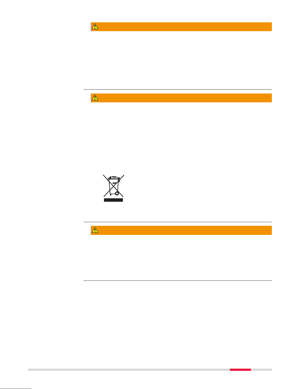
WARNING
roduct is improperly disposed of, the following can happen:
If polymer parts are burnt, poisonous gases are produced which may
impair health.
If batteries are damaged or are heated strongly, they can explode and
cause poisoning, burning, corrosion or environmental contamination.
By disposing of the product irresponsibly you may enable unauthorised
persons to use it in contravention of the regulations, exposing themselves
and third parties to the risk of severe injury and rendering the environment
liable to contamination.
The product must not be disposed with household waste.
ose of the product appropriately in accordance with
Disp
the national regulations in force in your country.
Always prevent access to the product by unauthorised
personnel.
Product-specific treatment and waste management information can be
r
eceived from your Leica Geosystems distributor.
WARNING
Improperly repaired equipment
Risk of injuries to users and equipment destruction due to lack of repair knowledge.
Precautions:
▶
Only Leica Geosystems authorised service centres are entitled to repair
these products.
Safety Directions 11
Page 12

1.5.2 Using the Product with a Signal Transmitter
DANGER
Clipping a transmitter clamp around a live utility
When a tr
might be present on the utility or at the transmitter plug connector, causing
you to receive an electric shock.
Precautions:
▶
▶
Connecting the cable set of the transmitter to a live utility
nnecting the cable set of the transmitter directly to a live utility can cause
Co
you to receive an electric shock.
Precautions:
▶
ansmitter clamp is clipped around a live utility, a hazardous signal
Do not clip a transmitter clamp around live utilities that have impaired or
no insulation.
Always ensure that the transmitter plug connector is connected to the
transmitter before you clip the transmitter clamp around a live utility.
DANGER
Never connect the cable set of the transmitter directly to a live electrical
utility.
DANGER
Power output of signal transmitter
he signal transmitter can output potentially lethal voltages!
T
Precautions:
▶
Take care when using the maximum power output of the signal transmitter.
▶
Take care when handling exposed or non-insulated connections, including
the transmitter’s cable set, the earth pin and the connection to the utility.
▶
Notify others who may be working on or around the utility.
WARNING
Removing the battery pack of the signal transmitter
R
emoving the battery pack of the signal transmitter might cause you to receive
an electric shock.
Precautions:
▶
Switch the signal transmitter off and remove any cable set or accessories
from the connection socket before removing the battery pack.
WARNING
Battery pack of the signal transmitter may get hot after prolonged use.
Risk o
f burning injuries.
Precautions:
▶
Avoid touching the hot battery pack.
▶
Allow the battery pack to cool down before removing it.
12 Safety Directions
Page 13
1.6 Electromagnetic Compatibility EMC
Description
The term Electromagnetic Compatibility is taken to mean the capability of the
roduct to function smoothly in an environment where electromagnetic radia-
p
tion and electrostatic discharges are present, and without causing electromagnetic disturbances to other equipment.
WARNING
Electromagnetic radiation
tromagnetic radiation can cause disturbances in other equipment.
Elec
Precautions:
▶
Although the product meets the strict regulations and standards which are
in force in this respect, Leica Geosystems cannot completely exclude the
possibility that other equipment may be disturbed.
CAUTION
Use of the product with accessories from other manufacturers. For
ample field computers, personal computers or other electronic equip-
ex
ment, non-standard cables or external batteries
This may cause disturbances in other equipment.
Precautions:
▶
Use only the equipment and accessories recommended by Leica Geosystems.
▶
When combined with the product, they meet the strict requirements stipulated by the guidelines and standards.
▶
When using computers, two-way radios or other electronic equipment, pay
attention to the information about electromagnetic compatibility provided
by the manufacturer.
CAUTION
Intense electromagnetic radiation. For example, near radio transmitters, transp
Although the product meets the strict regulations and standards which are in
force in this respect, Leica Geosystems cannot completely exclude the possibility that function of the product may be disturbed in such an electromagnetic
environment.
Precautions:
▶
Check the plausibility of results obtained under these conditions.
onders, two-way radios or diesel generators
Safety Directions 13
Page 14

CAUTION
Electromagnetic radiation due to improper connection of cables
If the p
two ends, for example external supply cables, interface cables, the permitted
level of electromagnetic radiation may be exceeded and the correct functioning
of other products may be impaired.
Precautions:
▶
Use of product with radio or digital cellular phone devices
Elec
tions, in medical devices, for example pacemakers or hearing aids and in aircraft. It can also affect humans and animals.
Precautions:
▶
▶
▶
▶
▶
roduct is operated with connecting cables attached at only one of their
While the product is in use, connecting cables, for example product to
external battery, product to computer, must be connected at both ends.
WARNING
tromagnetic fields can cause disturbances in other equipment, in installa-
Although the product meets the strict regulations and standards which are
in force in this respect, Leica Geosystems cannot completely exclude the
possibility that other equipment can be disturbed or that humans or animals can be affected.
Do not operate the product with radio or digital cellular phone devices in
the vicinity of filling stations or chemical installations, or in other areas
where an explosion hazard exists.
Do not operate the product with radio or digital cellular phone devices
near to medical equipment.
Do not operate the product with radio or digital cellular phone devices in
aircraft.
Do not operate the product with radio or digital cellular phone devices for
long periods with the product immediately next to your body.
1.7 FCC Statement, Applicable in U.S.
☞
The greyed paragraph below is only applicable for products without
r
adio.
14 Safety Directions
Page 15
WARNING
13297_001
This equipment has been tested and found to comply with the limits for a
lass B digital device, pursuant to part 15 of the FCC rules.
C
These limits are designed to provide reasonable protection against harmful
interference in a residential installation.
This equipment generates, uses and can radiate radio frequency energy and,
if not installed and used in accordance with the instructions, may cause
harmful interference to radio communications. However, there is no guarantee that interference will not occur in a particular installation.
If this equipment does cause harmful interference to radio or television
reception, which can be determined by turning the equipment off and on,
the user is encouraged to try to correct the interference by one or more of
the following measures:
•
eorient or relocate the receiving antenna.
R
•
Increase the separation between the equipment and the receiver.
•
Connect the equipment into an outlet on a circuit different from that to
which the receiver is connected.
•
Consult the dealer or an experienced radio/TV technician for help.
CAUTION
Changes or modifications not expressly approved by Leica Geosystems for
ompliance could void the user's authority to operate the equipment.
c
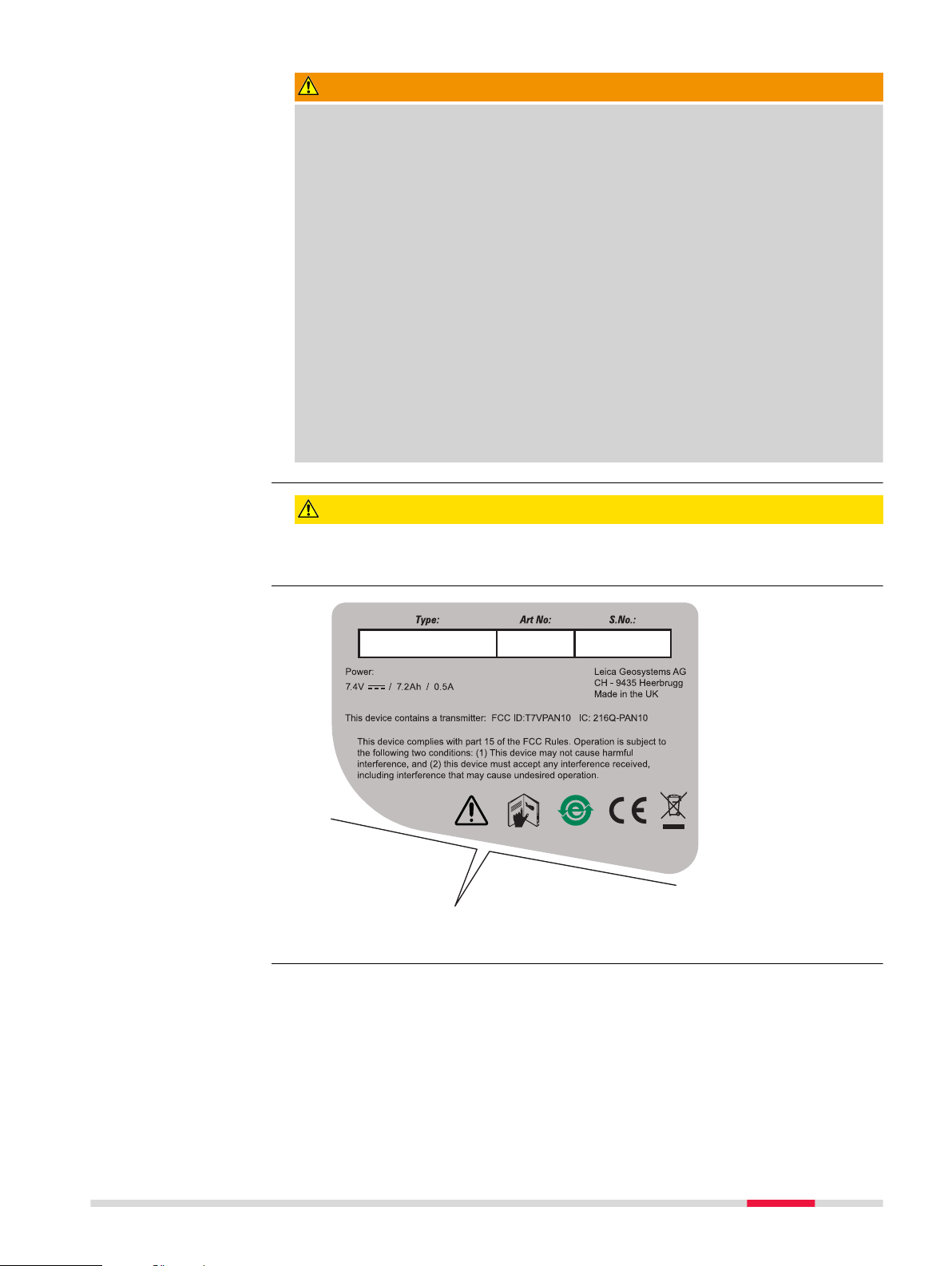
Labelling
DD220/DD230
Safety Directions 15
Page 16
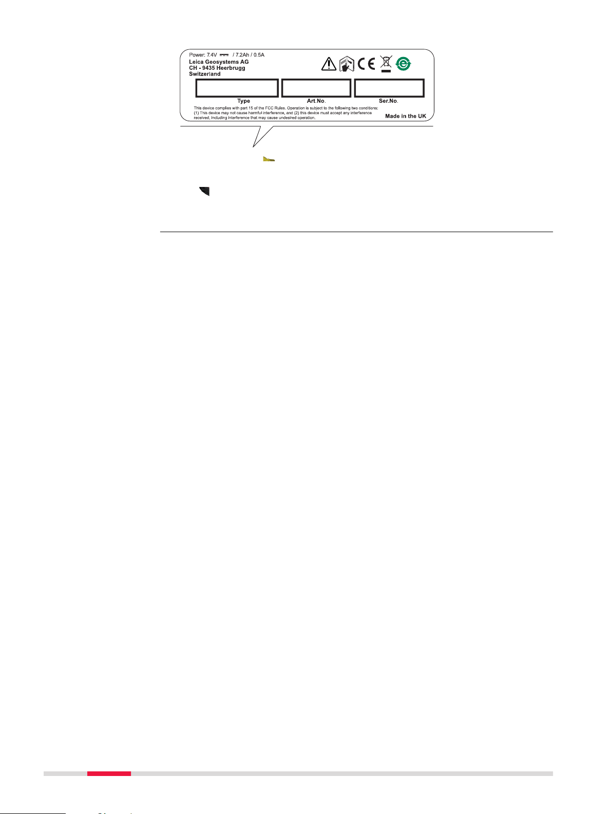
13298_001
Labelling DA series
transmitters
16 Safety Directions
Page 17
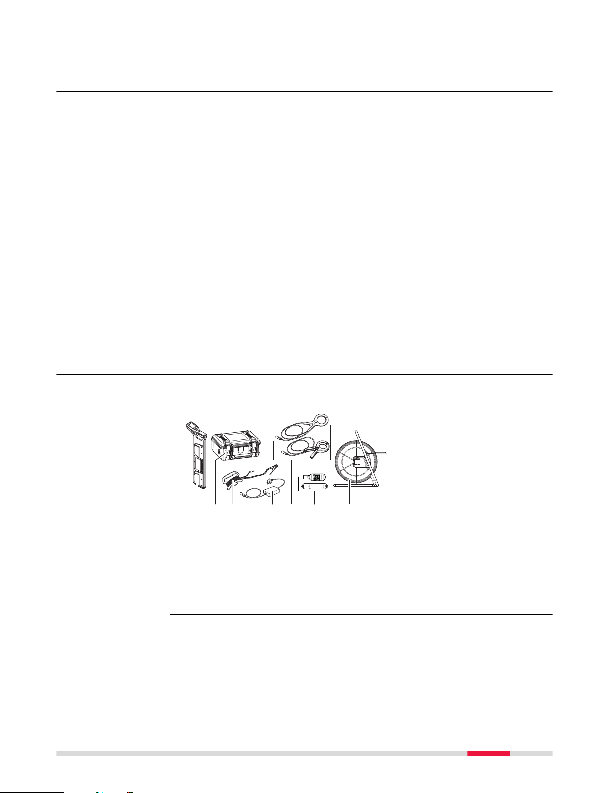
2 Description of the System
ab
c
d
e
f
g
13299_001
2.1 System Information
General description
Locators are used to detect buried conductive utilities that emit an electromag-
tic signal. Such a signal is generated as an electrical current passes through
ne
the utility.
Signal transmitters are used to apply a distinct signal to utilities with the following intention:
•
o improve the detection success.
T
•
To trace the route of a utility.
•
To make a depth or current measurement.
Accessories are used with the locator and transmitter to localise the position
o
f utilities, including some that are non-metallic.
The locators and transmitters described within this manual greatly facilitate the
search process and help to reduce the dangers and costs associated with utility
strikes. However, electromagnetic location depends on the utilities being conductive (metallic) and emitting a signal as current passes through them.
☞
Keep in mind that a locator on its own cannot detect all utilities. Take
car
e when excavating. We recommend that you adopt a safe system
which includes the planning of the search process in advance, the use
of utility maps, the use of locators and transmitters, and the use of
safe digging practices.
2.2 System Components
☞
The delivered components depend on the package ordered.
Available system
onents
comp
a Locator
b
Transmitter
c Transmitter Cable Set Extension
d Property Plug Connector
e Transmitter Clamps
f Sondes
g Trace Rod (non-metallic utility tracer)
Description of the System 17
Page 18
2.3 Locator Components
a
b
d
e
f
c
13300_001
013301_001
b
c
a
d
e
f
14479_001
Description of
onents DD220/
comp
DD230 locators
2.4 Signal Transmitter Components
a Display
b
Locator keyboard
c USB port
d Trigger
e Battery compartment
f Locator foot (wear part)
Description of
transmitter
comp
onents
a Accessory compartment
Connection socket
b
c Battery compartment and USB
port
d Signal transmitter keyboard
e Speaker
f Induction arrow
2.5 Li-Ion Battery Pack
Li-Ion battery pack
The Li-Ion battery pack is delivered with an energy content as low as possible
and needs t
o be woke up prior to use.
To wake up the Li-Ion battery pack, do the following:
1. Connect the charger plug into the charge
jack o
n the battery pack.
18 Description of the System
Page 19
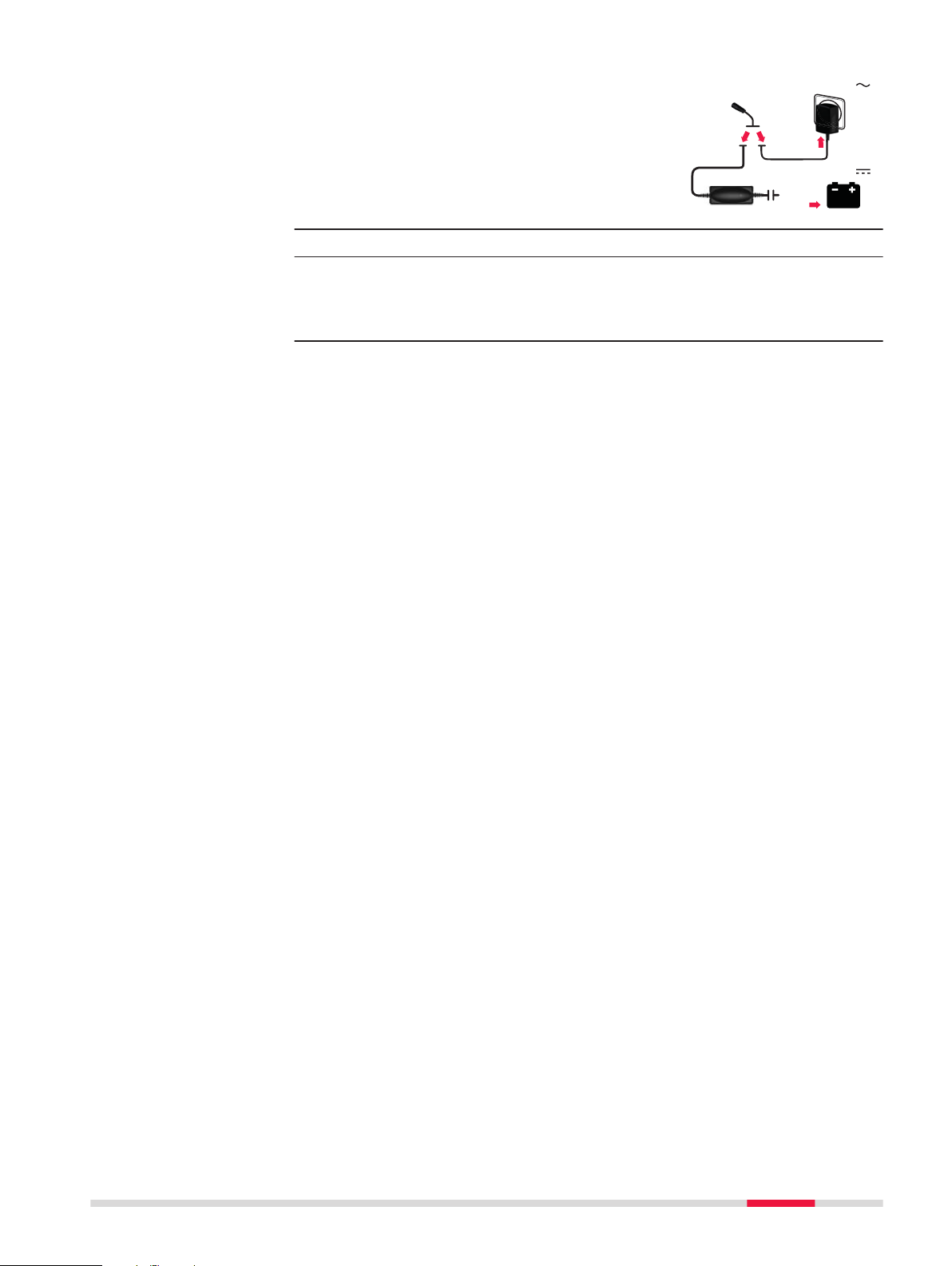
2. Plug the connector into a suitable power
14480_001
12/24 V
100-240 V
ource.
s
☞
☞
☞
The battery pack should be fully charged before use.
Result:
T
he small LED next to the charge jack flashes at a fast rate to indicate the wake up process, then flashes at a slower rate to indicate
that the battery pack is active and charging.
Applicable to the DD220/DD230 locators and DA Signal Transmitters.
Description of the System 19
Page 20
3 Operation of the Locator
13302_001
13303_001
3.1 Keyboard
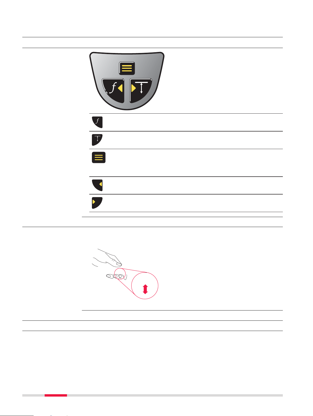
DD220/DD230 locator
k
eyboard
Function key
Pr
ess and release to change the search mode.
Depth Estimation key
Pr
ess and release to take a depth reading.
Menu key
Pr
ess and hold to display the Locator main menu or to return back to
the locate screen.
Press and release to select a menu option.
Left navigation key
Pr
ess and release to select the previous menu option.
Right navigation key
Pr
ess and release to select the next menu option.
3.2 Turning On / Turning Off
Turning on and off
e DD220/DD230
th
Press and hold the trigger to turn on and operate the locator.
R
elease the trigger to turn off the locator.
3.3 Display Screens
3.3.1 The Customisation Screens
Set the regional
eferences
pr
The customisation screens are displayed only for the first time the locator is
pu
t into operation. The screens allow you to set the locator to your regional
preferences.
20 Operation of the Locator
Page 21
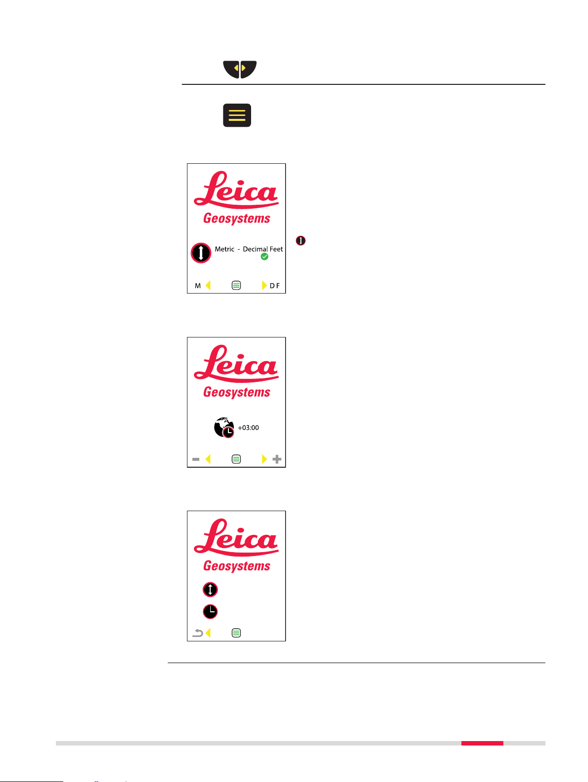
1. Use the navigation keys to alter the selection.
14329_001
14330_001
14331_001
2. Press the menu key to confirm the selection.
Units of Measurement
This screen allows you to set up your preferred units
f measurement for depth estimation.
o
☞
To change the units of measurement later
on, use the menu option in the Settings
menu. Refer to " Submenu Settings" within
"3.4.2 Menu Options".
Time Zone Settings (model specific option)
This screen allows you to adjust the time zone set-
o suit your geographic region. The default time
tings t
is Universal Time Coordinate (UTC). Time zone offsets
are shown in Appendix A Time Zone Offsets.
Set up the hours and minutes.
Confirmation Screen
This screen allows you to confirm your changes or to
eturn to the previous screens and update the set-
r
tings.
To confirm your settings, press the menu key.
To return and update, press the left navigation key.
Operation of the Locator 21
Page 22
3.3.2 The Locate Screen
500
a
b
c
d
e
f
13146_001
13147_001
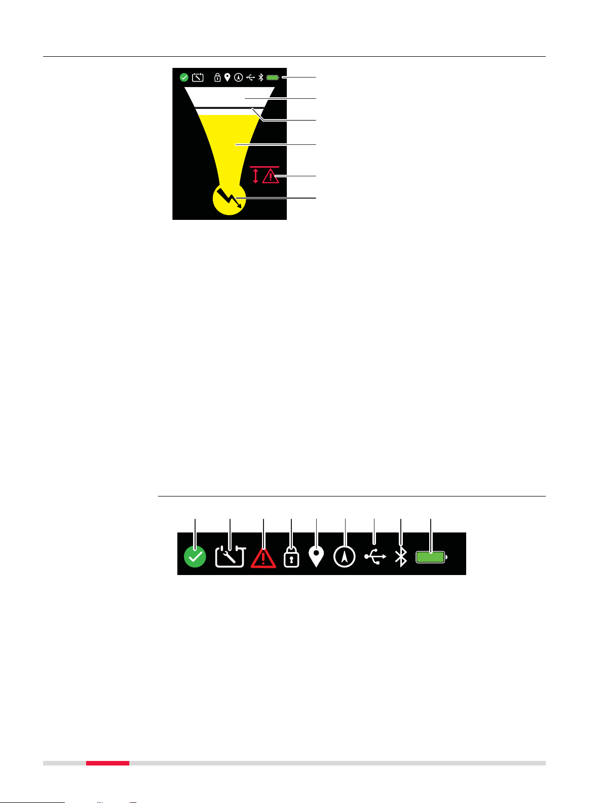
a b c d e f g h i
Description of the
scr
een
a) S
tatus bar
Provides information on product and feature selection
b) Numeric Peak Indicator
•
Increases when approaching a utility or sonde and decreases when
moving away.
•
Provides the highest peak reading when directly over the utility or
sonde.
•
Can be used to distinguish between utilities when a signal transmitter
is used.
c) Peak Indicator
•
Indicates the highest peak reading on the locate scale.
•
Remains at the peak position for a short period of time before falling
back.
d) Locate Scale
•
Increases when approaching a utility or sonde and decreases when
moving away.
•
Provides a peak reading when directly over the utility or sonde.
e) Alerts
Alerts are displayed to indicate hazardous situations or incorrect use.
f) Search Mode Indicator
Displays the currently selected search mode.
Status bar icons
22 Operation of the Locator
Page 23
a) Health Ch
b)a)
013194_001
13148_001
eck
Health Check passed within the last 24 hours.
Health Check process prohibited, e.g. if Health Check is activated in
h levels of electrical interference.
hig
b) Scheduled Maintenance
Planned maintenance is due for the locator. To adjust the settings, refer to
" Submenu Maintenance" ("3.4.2 Menu Options").
c) Fault Alert
Indicates a potential product defect.
d) Mode Lock
Locator starts up in the search mode that was used last.
e) Point of Interest
Model-specific option. Refer to "8.3 Point of Interest".
f) GPS status
Model-specific option. Refer to "8.2 Internal GPS".
g) USB status
Refer to "7.2 Locator USB Connectivity ".
h) Bluetooth status
Model-specific option. Refer to "7.1 Locator Bluetooth Connectivity".
i) Battery condition
Battery Low. Refer to "9 Batteries".
Locate alerts
a) Swing Alert
Indicates excessive swinging during use. To adjust the settings, refer to
"Submenu Alerts" ("3.4.2 Menu Options").
b) Hazard Zone
Indicates the close proximity of a utility. Works in all search modes except
in Radio mode. To adjust the settings, refer to " Submenu Alerts" ("3.4.2
Menu Options").
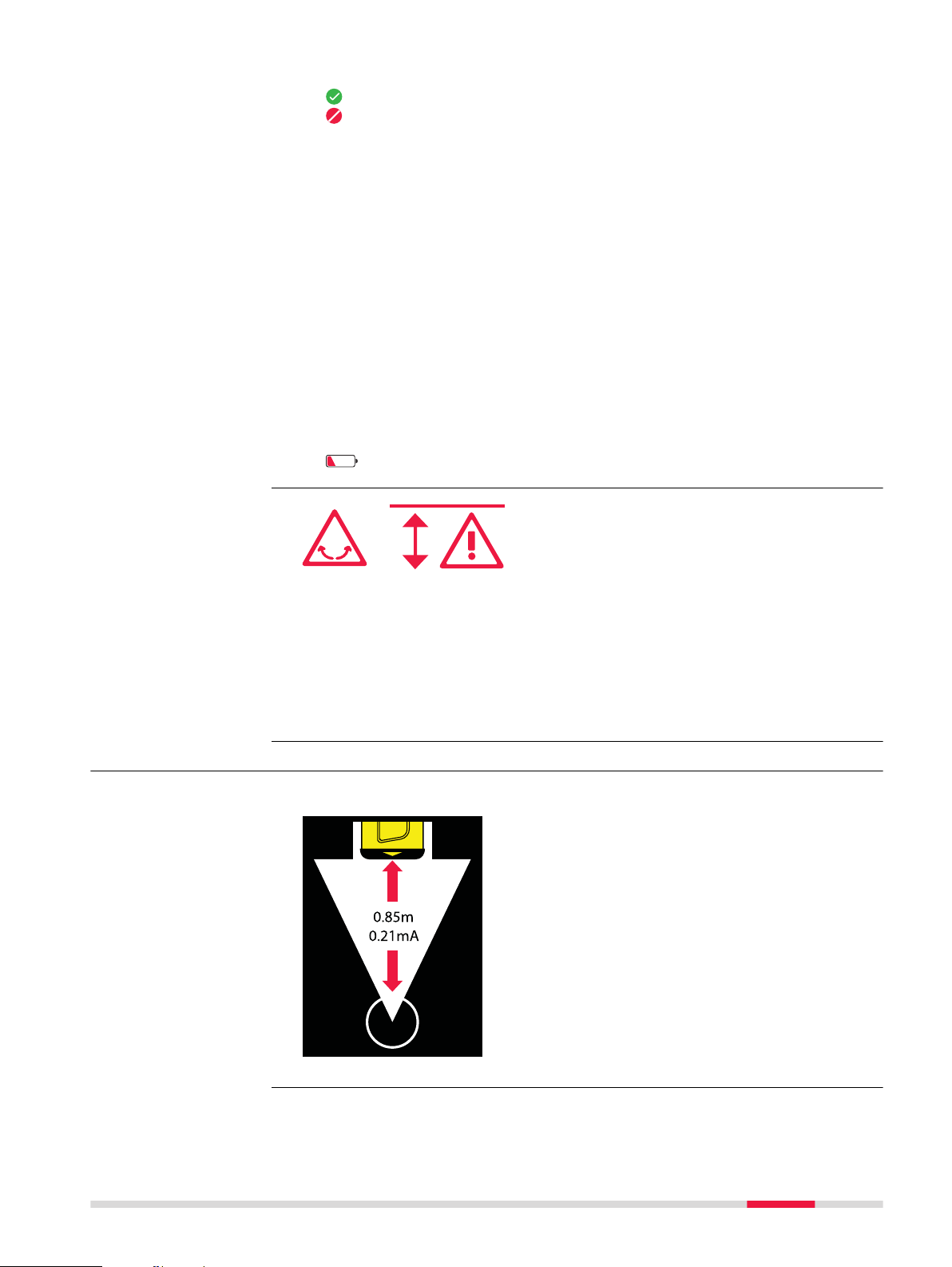
3.3.3 The Depth Estimation Screens
Utility line depth
This screen indicates the depth of a buried utility.
☞
Note that the depth is calculated as dis-
e to the centre of the utility!
tanc
Operation of the Locator 23
Page 24
13149_001
14320_001
14321_001
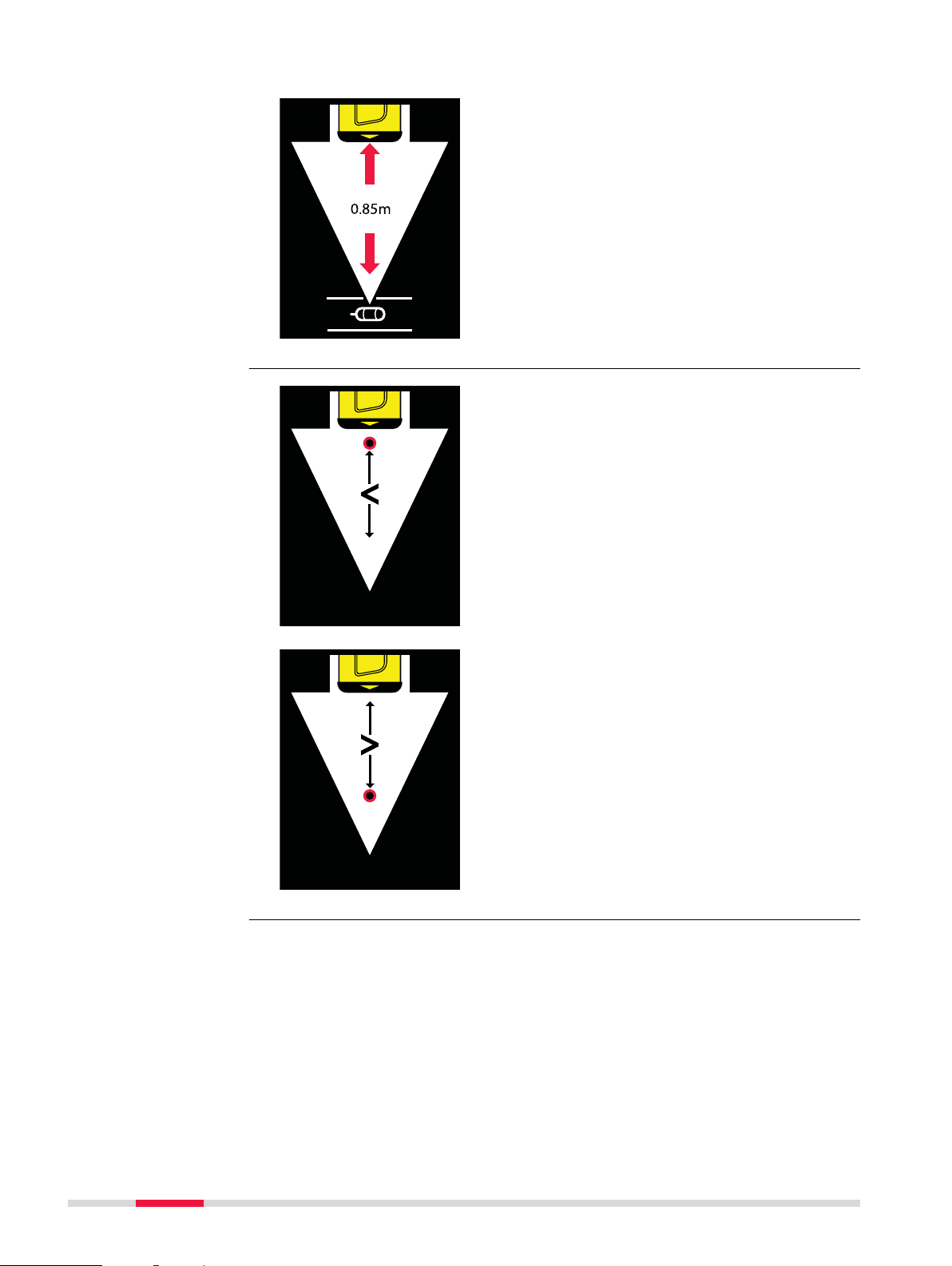
Sonde depth
This screen indicates the depth of a sonde within a pipe.
Depth out of range
☞
Note that the depth is calculated as dis-
e to the sonde within the pipe!
tanc
This screen indicates that the depth of the utility
or sonde is less than the minimum depth range.
This screen indicates that the depth of the utility
o
r sonde is greater than the maximum depth
range.
24 Operation of the Locator
Page 25

14322_001
14323_001
Signal out of range
This screen indicates that the signal source is too
o provide a depth reading.
low t
This screen indicates that the signal source is too
high to provide a depth reading.
Operation of the Locator 25
Page 26

3.4 Locator Menu
a
cde c
b
cde c
13155_001
3.4.1 Access and Navigation
Locator main menu
d submenus
an
The Locator menu is used to display information or to update settings.
A main menu is us
available options for the selected category.
a Locator main menu
Submenu (Example)
b
c On-screen guidance arrows that indicate the previous and next menu
option.
d Currently highlighted menu option.
e On-screen menu icon. A green icon indicates an accessible option, a grey
icon indicates a read-only option.
ed to display the main categories. A submenu displays the
How to access and
navi
gate through the
menu
☞
The Locator must be switched on throughout the process.
Press and hold the menu key to display the Locator main menu.
☞
Use the navigation keys to highlight a menu option.
Press and release the menu key to select the highlighted option.
When displaying the main menu, the option Health Ch
is highlighted by default.
eck
The submenu for the selected option is displayed.
Use the navigation keys to highlight a menu option.
Press and release the menu key to select the highlighted option.
Use the navigation keys to adjust the option.
Press and release the menu key to confirm the changes and return
to the submenu.
Select this option to go back one level.
26 Operation of the Locator
Page 27

Select this option to close the menu and display the Locate screen.
☞
You can also press and hold the menu key to display the
cate screen.
Lo
Commonly used menu
icons
Icon Description
3.4.2 Menu Options
Main menu
Select this option to perform a Health Check.
Health Ch
ware.
Refer to "10.1 Locator Health Check".
Videos.
ntains short animations on key product features or product usage.
Co
Information.
ntains options for product and owner information.
Co
Alerts.
ntains options for alerts and configuration.
Co
This icon indicates an active option or a good condi-
n.
tio
This icon indicates an inactive option or a failed condi-
n.
tio
This icon indicates a prohibited use or a fault.
This icon indicates a user defined or activated option.
eck is a function check on the locators hardware and soft-
Submenu Videos
☞
Home.
t this option to return to the Locate screen.
Selec
Communication.
ntains options for communication (connectivity) and configuration.
Co
Settings.
ntains options for product settings and configuration.
Co
Maintenance.
ntains options for maintenance and configuration.
Co
Select from the main menu.
Select this option to play a short animation on how to use the loca-
or in Power or Radio mode.
t
Select this option to play a short animation on how to use the loca-
or with the signal transmitter in Connection Mode.
t
Operation of the Locator 27
Page 28

Select this option to play a short animation on how to use the loca-
or with the signal transmitter in Induction mode.
t
Select this option to play a short animation on how to use the locat
or with a sonde.
Select this option to play a short animation on how to perform a
roduct Health Check.
p
Select this option to play a short animation on how to perform a cali-
ration verification.
b
Select this option to return to the main menu.
Submenu Information
☞
Select from the main menu.
Select this option to display company or owner information.
Select this option to display company or owner telephone number.
Select this option to display user name or fleet number.
Select this option to display product information, for example serial
er.
numb
Select this option to display the e-mail address.
Select this option to display the web address.
Select this option to return to the main menu.
Submenu Alerts
28 Operation of the Locator
☞
Select from the main menu.
Select this option to adjust the Hazard Zone activation point.
vailable settings:
A
•
(OFF): Alert function is not active.
•
0.3 m (12 inche
the defined range.
•
0.5 m (20 inches): Alert is displayed if a utility is detected within
the defined range.
Select this option to adjust the Swing Alert settings.
vailable settings:
A
•
•
(ON)
(OFF)
s): Alert is displayed if a utility is detected within
Page 29

Select this option to display the fault code.
Indicates a product fault. The fault code is displayed. For a list of
ault codes, refer to "10.3 Locator Fault Codes".
f
Indicates that the product condition is good.
Select this option to return to the main menu.
Submenu
aintenance
M
Submenu Settings
☞
☞
Select
Select this option to adjust the Health Check activation.
A
vailable settings:
•
•
•
Displays the number of months to the next calibration.
Select this option to display the recent maintenance history.
Pr
ess and release the menu key to display the report.
Select this option to adjust the scheduled maintenance settings.
vailable settings: ON (
A
Select this option to return to the main menu.
Select from the main menu.
Select this option to adjust the products volume level.
from the main menu.
User defined
DD: Dail
MM: Monthly
y
) or OFF ( ).
Select this option to adjust the Numeric Peak Indicator.
vailable settings:
A
•
•
Select this option to adjust the display time for the Peak Indicator.
A
•
•
Select this option to adjust the Mode Lock setting.
A
•
•
Select this option to adjust the measurement units for depth estimatio
Available settings:
•
•
•
(ON)
(OFF)
vailable settings:
(ON)
(OFF)
vailable settings:
ON: Locator starts up in the search mode that was used last.
OFF: Locator starts up in the default search mode.
n.
Metric
Decimal Feet
Off (controlled by external software)
Operation of the Locator 29
Page 30

Select this option to adjust the Point-of-Interest setting.
vailable settings:
A
•
Select a marker in the desired colour to activate the POI function.
•
Select
Select this option to adjust the display brightness.
Select this option to return to the main menu.
to turn off the POI function.
Submenu
Communic
ation
☞
Select from the main menu.
Model-specific option:
t this option to adjust the products Bluetooth options.
Selec
Available settings:
•
•
•
•
•
R
Select this option to return to the main menu.
DD SMART
BT1: B
locators.
BT2: Backward compatibility with Bluetooth-enabled iSeries
locators.
User configurable option, can be customised using the loca-
ors management software.
t
Bluetooth is turned off.
efer to "7.1 Locator Bluetooth Connectivity".
3.5 Search Modes
Available search
modes
Search Mode Description
Auto mode Combined detection of Power and Radio modes.
ackward compatibility with Bluetooth-enabled iSeries
☞
This mode facilitates a one-step sweep
earch process.
s
Power mode This mode is used to detect electrical cables.
☞
Radio mode This mode is used to detect metallic pipes or cables,
including telecoms and electrical.
☞
Power mode is dependent on an electrical
current flowing through a cable. Keep in
mind that not all electrical cables carry a
detectable signal and thus pose a serious
risk, for example supplies to unilluminated
street lights, unoccupied buildings or balanced three-phase cables.
Radio mode is dependent on reradiated
radio waves originating from radio masts.
Keep in mind that signal availability can
vary or be restricted depending on factors
including line of site, signal application or
routine mast maintenance.
30 Operation of the Locator
Page 31

Search Mode Description
Signal Transmitter
de
mo
Used in conjunction with a signal transmitter:
•
To improve the detectability of utilities.
•
To trace a specific utility.
•
To make a depth or current measurement.
☞
•
•
•
•
Example:
A 131 kHz frequency has a greater ability to couple
onto other utilities, jump over insulated pipe joints,
travel down small-diameter cables or pot-ended (terminated) cables.
Sonde mode Used in conjunction with a sonde:
•
•
•
☞
•
•
Keep in mind the following:
her frequencies couple onto utilities more
Hig
easily than lower frequencies.
Higher frequencies travel shorter distances; the
higher the frequency the less the distance travelled.
Higher frequencies are likely to couple onto
other utilities; the higher the frequency the
greater the spread.
Higher frequencies are useful for avoidance
activities.
T
o trace the route of a pipe or duct, including
non-metallic variants.
To locate a blockage or collapse.
To make a depth measurement.
Keep in mind that various sondes are avail-
or specific task-based applications:
able f
ndes with higher frequencies are used for
So
generic pipe or duct tracing.
Lower frequencies (512 Hz, 640 Hz) work best
for metal pipes.
WARNING
The absence of a positive indication does not guarantee the non-existence of a
utility.
Utilities without a detectable signal may be present.
The locators can only locate non-metallic utilities such as plastic pipes, typically
used by the water and gas utilities, with the use of appropriate accessories.
Precautions:
▶
Always excavate with care.
How to select a
ch mode
sear
The Search Mode indicator cycles through in the following order:
Press the Function key on the locator keyboard to select a search
de.
mo
Operation of the Locator 31
Page 32

a) b) c) d) e)
13195_001
a Auto Mode
131kHz8kHz 33kHz
13324_001
Power Mode
b
c Radio Mode
d Signal Transmitter Mode
e Sonde Mode
Frequency selection
Using the locator with a signal transmitter
he Signal Transmitter mode features an auto-select option (indicated by ~TX).
T
In Auto mode the locator locks onto the signal transmitters output and updates
the Search Mode indicator with the selected frequency.
☞
Auto mode is influenced by the ability to detect the signal transmitters output. For long distance tracing or low signal outputs it is recommended to manually select the required frequency on the locator.
Using the locator with a sonde
The default search mode when using a sonde is Sonde Mode (33 kHz).
Manual selection of a signal transmitter or sonde frequency
Action Result
1. Press the Function key to select
either the Signal T
ransmitter or the
Sonde mode.
2. Press and release the menu key.
The Search Mode indicator
displays the currently selected frequency. The on-screen
guidance arrows indicate the
previous and next frequency
value.
3. Use the navigation keys to select the
equired frequency.
r
32 Operation of the Locator
Page 33

Action Result
13325_001
4. Press and release the menu key to
onfirm the selection.
c
The Search Mode indicator
displays the selected frequency.
☞
To save the selection throughout the locator’s use, set the Mode
ck setting to ON. Refer to " Submenu Settings" within "3.4.2
Lo
Menu Options".
Operation of the Locator 33
Page 34

4 Operation of the Transmitter
13192_001
ab e fc d
13193_001
4.1 Keyboard
Transmitter keyboard
4.2 Turning On / Turning Off
Turning on and off
th
e transmitter
Press the Power key to turn the transmitter on or off.
a Power key
b
Power Output key and LED
indicators
c Low Battery LED indicator
d Connection Mode LED indica-
tor
e Frequency key and LED indica-
tors
f Mute key
34 Operation of the Transmitter
Page 35

5 Applications
45 450 45450500
13210_001
5.1 How to Pinpoint a Utility
Pinpointing process
To help you pinpoint a utility, the locator provides a visual and an audible
esponse.
r
Visual response
When the lo
Locate screen displays a peak reading. Refer to "3.3.2 The Locate Screen".
Locate Scale
cator is positioned directly over a utility and at 90° to it, the
•
•
•
eases when approaching a utility or sonde and decreases
Incr
when moving away.
Provides a peak reading when directly over the utility or
sonde.
Decreases when moving away from the utility.
Peak Indicator
•
Indica
tes the highest peak reading on the locate scale.
•
Remains at the peak position for a short period of time
before falling back.
Numeric Peak Indicator
•
•
•
•
Audible response
T
o assist in the pinpointing process, the audio output automatically adjusts
over the peak reading to provide a narrower response.
☞
Mark the position of a utility with marker paint, pegs, flags or something similar
eases when approaching a utility or sonde and decreases
Incr
when moving away.
Provides the highest peak reading when directly over the
utility or sonde.
Decreases when moving away from the utility.
Can be used to distinguish between utilities when a signal
transmitter is used.
. Never drive pegs into the ground over the utility!
Applications 35
Page 36

☞
13196_001
13198_001
13199_001
13201_001
☞
The signal strength indicators do not indicate the size, depth or type
f a utility.
o
To ascertain an estimated depth of the utility, use a signal transmitter
or a sonde. Refer to "6 Estimating Depth and Current of a Utility".
5.2 How to Trace a Utility
Tracing process
1. Pinpoint a utility by finding the peak reading.
he peak reading is found when the locator
T
is positioned directly over a utility and at 90°
to it.
2. Rotate the Locator around its axis until the
signal strength indicators are at a minimum.
3. When the signal strength indicators are at a
minimum, the blade o
f the locator is in line
with the utility and indicates its direction.
4. Trace the route of the utility by repeating the
ollowing process:
f
•
Pinpoint the utility.
•
Determine the direction of the utility.
•
Follow the direction of the utility.
5.3 How to Conduct a Sweep Search
Sweep Search Process
Before the sweep search, define the work area to be excavated and inspect
ea for signs of buried utilities, such as:
this ar
•
Recent trenching
•
Buried utility marker posts
•
Overhead lines that run down poles and underground
•
Access chamber covers
36 Applications
Page 37

1. Set the locator to Power mode.
13202_001
13211_001
13212_001
13265_001
13266_001
500
13205_001
☞
Ensure that the locator is held upright
and close to the ground. Take care not to
swing the locator.
2. Cross the site from left to right until the
de
fined area is covered.
3. Turn through 90 ° and repeat the proc-
ss.
e
4. Pinpoint a utility by finding the peak
eading. The peak reading is found when
r
the locator is positioned directly over a
utility and at 90° to it. Mark the position
of a utility with marker paint, pegs, flags
or something similar.
☞
Never drive pegs into the
ground over the utility!
☞
Activate the Hazard Zone alert
to indicate the presence of
buried utilities which may be
close to the surface.
5. Set the locator to Radio mode and
epeat the sweep search process.
r
Continue with this process until either a
signal is detected or you are satisfied
that the area has been adequately tested.
Applications 37
Page 38

☞
250 425
500
13278_001
13267_001
To conduct a one-step Sweep Search process or to provide a fast scan
or large work areas, the locator can be used in Auto mode. To obtain
f
an improved definition of a detected utility, use the locator in an individual mode.
5.4 Using the Transmitter in Induction Mode
5.4.1 General Information
Induction mode
Induction is a quick and simple way to apply a signal to a utility without the
o make any physical connection to it. The transmitter uses an internal
need t
aerial to transmit the signal to the utility.
☞
☞
☞
☞
☞
Work at least 10 m/33 ft away from the transmitter to avoid airborne
signals. R
Coupling efficiency is best at 33 kHz.
The signal can also apply itself to other utilities within close proximity
to the transmitter, depending on their depth and direction.
To increase the battery life and to reduce the possibility that the signal is applied to adjacent utilities, reduce the signal output.
The Numeric Peak Indicator can be used to indicate multiple utilities
or to assist tracing. The utility with the maximum value is typically the
one closest to the transmitter or the one directly connected to.
eposition the Transmitter if necessary.
Standard process for
duction mode
In
38 Applications
1. Turn on the transmitter.
☞
Ensure that any connection
cable
s or accessories are disconnected and the battery
level is adequate.
Page 39

2. Select the required power output and
13280_001
13292_001
13206_001
13293_001
500
13305_001
requency.
f
3. Place the transmitter over the utility with
the arrows running in line with the suspected direction of the utility.
The internal aerial directly induces the
tracing signal onto the utility.
4. Set the locator to Signal Transmitter
mo
de and select the required frequency.
5. Using the Sweep Search process, search
the wo
rk area until either a signal is
detected or you are satisfied that the
area has been adequately tested.
Refer to "5.3 How to Conduct a Sweep
Search".
Trace a utility as required. Refer to "5.2
How to Trace a Utility".
☞
Maintain a distance of 10 m/
33 ft from the transmitter to
avoid airborne signals and a
decline in the search process.
Reposition the transmitter if
required.
5.4.2 Induction Mode: Nulling-Out Method
Nulling-Out method
Use the Nulling-Out method to confirm that the locator and transmitter are on
the same u
☞
tility or to identify hidden utilities in close proximity to each other.
The transmitter and locator need to be set for use in induction mode.
R
efer to " Standard process for Induction mode".
1. Position the locator over the utility with
the highest numeric signal strength.
Applications 39
Page 40

2. To confirm that the transmitter and the
13308_001
13308_001
13310_001
13311_001
cator are on the same utility, place the
lo
signal transmitter upright and directly
over the utility.
☞
3. If the transmitter and the locater are on
the same utility, the Numeric Peak Indicator on the locator significantly decreases.
Either the speaker or the connection socket should be on
the ground.
☞
4. Using the Sweep Search process, search
The Numeric Peak Indicator on the locator can be used to correct the
p
osition of the transmitter. Slightly move the transmitter left or right
over the utility until the locate screen of the locator shows the lowest reading. It is possible to obtain the value “000”.
the work area to identify previously hidden utilities.
☞
Pinpoint and trace utilities until
you are satisfied that the area
has been adequately tested.
5.4.3 Induction Mode: Parallel-Sweep Method
Parallel-Sweep
ethod
m
Use the Parallel-Sweep method to cover a large area or to verify the presence
f utilities before using the standard process for induction mode.
o
☞
☞
1. Person operating the transmitter:
Two people are required for this process: one for operating the locator and one for operating the transmitter.
Set the transmitter and locator to 33 kHz.
Hold the transmitter close to the ground
with the arrows on the lid vertical and
with the lid facing the person who operates the locator.
Person operating the locator:
Position the locator at a minimum distance of 10 m/33 ft away from the transmitter.
40 Applications
Page 41

2. Both persons:
13312_001
500
13313_001
14303_001
14304_001
tart walking parallel to each other.
S
☞
3. In the presence of a detectable utility,
the locator emits a tone and the signal
strength indicators rise and fall as you
pass over the utility.
Return to the position where the Locate
screen shows a peak reading. Mark the
position of a utility with marker paint,
pegs, flags or something similar.
☞
☞
The tracing signal is induced
directly onto the utility and
indicated on the locator.
Never drive pegs into the
ground over the utility!
To trace a specific utility, use
the pinpointing and tracing
methods. Refer to "5.1 How
to Pinpoint a Utility" and "5.2
How to Trace a Utility".
4. Turn through 90 ° and repeat the process.
☞
Pinpoint and trace utilities until you are satisfied that the area has
b
een adequately tested.
5.4.4 Induction Mode: Radial-Sweep Method
Radial-Sweep method
Use the Radial-Sweep method to discover utilities coming from a known point
such as a t
☞
☞
1. Person operating the transmitter:
elecommunications chamber.
Two people are required for this process: one for operating the loca-
or and one for operating the transmitter.
t
Set the transmitter and locator to 33 kHz.
Hold the transmitter close to the ground
with the arrows on the lid vertical and
with the lid facing the person who operates the locator.
Person operating the locator:
Position the locator at a minimum distance of 10 m/33 ft away from the transmitter.
Applications 41
Page 42

2. Both persons:
14305_001
500
14306_001
14340_001
tart walking parallel to each other, cir-
S
cling the target area.
☞
3. In the presence of a detectable utility,
the locator emits a tone and the signal
strength indicators rise and fall as you
pass over the utility.
Return to the position where the Locate
screen shows a peak reading. Mark the
position of a utility with marker paint,
pegs, flags or something similar.
☞
☞
The tracing signal is induced
directly onto the utility and
indicated on the locator.
Never drive pegs into the
ground over the utility!
To trace a specific utility, use
the pinpointing and tracing
methods. Refer to "5.1 How
to Pinpoint a Utility" and "5.2
How to Trace a Utility".
☞
Pinpoint and trace utilities until you are
satisfied that the area has been adequately tested.
5.5 Using the Transmitter in Connection Mode
5.5.1 General Information
Connection mode
Connection mode is the most efficient way to apply a signal to a utility. The
cable s
to the utility which is to be traced or identified.
☞
☞
☞
☞
☞
et of the transmitter or any of the available accessories are connected
Whenever possible, use the transmitter in connection mode, espe-
y for taking a depth reading.
ciall
The Numeric Peak Indicator can be used to indicate multiple utilities
or to assist tracing. The utility with the maximum value is typically the
one connected to.
The black connection cable can be connected to other metallic structures which go into the ground, such as iron grids or metal covers of
access chambers.
In dry conditions it may be necessary to add water around the earth
point to get a good connection.
When using the connection cable set, examine the connection points
and remove contamination if a continuous audible output is not achieved.
42 Applications
Page 43

☞
14341_001
14343_001
14345_001
13279_001
☞
An extension cable is available to extend either the red or black cables
n the connection cable set.
o
Reducing the signal output helps to extend the battery life and to
reduce the amount of signal applied to adjacent utilities.
5.5.2 Direct Connection Mode
Using the transmitter
ect Connection
in Dir
mode
1. Plug the transmitters cable set into the
onnection socket.
c
2. Ensuring that no utilities are below, push
the Earth Pin into the ground and connect the black cable to the Earth Pin.
☞
☞
3. Connect the red cable to the utility.
☞
☞
☞
For more safety, we recommend pushing the Earth pin
into the ground at an angle of
45 degrees.
For best performance, position
the Earth pin and black cable
at 90 degrees to the suspected direction of the utility.
Never connect the red cable
directly to an electrical cable!
Connecting the red cable to
the metal framework of earthbonded electrical installations
such as street lights, pumps or
motorised gate housings,
improves the detectability of
low-loaded electrical cables.
For best performance, connect
to bare metal.
Using the combination of
33 kHz and 131 kHz frequencies can improve the detectability of small diameter cables
or their short runs.
4. Turn on the transmitter.
☞
Ensure that the Connection
Mode LED indicator is on and
the battery level is adequate.
Applications 43
Page 44

5. Select the required frequency and power
13280_001
13206_001
14346_001
500
14347_001
tput.
ou
To indicate that the tracing signal reaches a good level, the Power Output LED
indicator and the audible tone change
from pulsed to continuous.
6. Set the locator to Signal Transmitter
mode and select the required frequency.
7. At a distance of 5 m (16 ft) to the connec
tion point, circle around the connec-
tion point.
8. In the presence of a detectable utility,
cator emits a tone and the signal
the lo
strength indicators rise and fall as you
pass over the utility.
Return to the position where the Locate
screen shows a peak reading. Mark the
position of a utility with marker paint,
pegs, flags or something similar.
☞
Never drive pegs into the
ground over the utility!
☞
To trace a specific utility, use
the pinpointing and tracing
methods. Refer to "5.1 How
to Pinpoint a Utility" and "5.2
How to Trace a Utility".
☞
Pinpoint and trace utilities until you are satisfied that the area has
een adequately tested.
b
5.5.3 Connection Mode: 131 kHZ Cable-Wrap Technique
Using the cable-wrap
tec
hnique
Sometimes it can be difficult to directly connect the transmitter to a utility. In
this cas
e, use the cable-wrap technique to apply a signal to a cable.
☞
For this process, the frequency of the transmitter should be set to
131 kHz
.
44 Applications
Page 45

1. Plug the transmitters cable set into the
14341_001
14343_001
14353_001
13279_001
13280_001
13206_001
onnection socket.
c
2. Ensuring that no utilities are below, push
the Earth Pin into the ground and connect the black cable to the Earth Pin.
☞
For more safety, we recommend pushing the Earth pin
into the ground at an angle of
45 degrees.
☞
For best performance, position
the Earth pin and black cable
at 90 degrees to the suspect
direction of the utility.
3. Wrap the red cable around the utility.
☞
Never connect the red cable
directly to an electrical cable!
☞
To increase performance,
increase the amount of wraps.
4. Turn on the transmitter.
☞
Ensure that the Connection
Mo
de LED indicator is on and
the battery level of the transmitter is adequate.
5. Select the required power output level
et the frequency output to
and s
131 kHz.
To indicate that the tracing signal reaches a good level, the Power Output LED
indicator and the audible tone change
from pulsed to continuous.
6. Set the locator to Signal Transmitter
de and select the required frequency.
mo
Applications 45
Page 46

7. At a distance of 5 m (16 ft) to the con-
14354_001
500
14355_001
13204_001
a
b
c
d
tion point, circle around the connec-
nec
tion point.
8. In the presence of a detectable utility,
the locator emits a tone and the signal
strength indicators rise and fall as you
pass over the utility.
Return to the position where the Locate
screen shows a peak reading. Mark the
position of a utility with marker paint,
pegs, flags or something similar.
☞
☞
Never drive pegs into the
ground over the utility!
To trace a specific utility, use
the pinpointing and tracing
methods. Refer to "5.1 How
to Pinpoint a Utility" and "5.2
How to Trace a Utility".
☞
Pinpoint and trace utilities until you are satisfied that the area has
been adequately tested.
5.6 How to Use the Trace Rod
5.6.1 General Information
Description
Description of
onents
comp
The Trace Rod is a utility tracer enabling small diameter non-conductive pipes,
ducts, conduit or drains to be traced. It can be used in Line mode to find the
route of the duct or Sonde mode to find a blockage.
46 Applications
Page 47

a) Son
14356_001
14341_001
14343_001
14537_001
de
Using Sonde mode, the sonde helps to pinpoint the end point of the trace
rod.
b) Line
Flexible, glass-fibre sheathed rod, which incorporates copper wires to conduct the signal.
Using Line mode, the rod helps to trace the route of a utility.
c) Connection terminals
Used to connect to the signal transmitter.
d) Frame
Houses the flexible rod. Can be used in both vertical (as in illustration) and
horizontal orientation.
5.6.2 Locating a Utility Using the Trace Rod
Using the trace rod in
e mode
Lin
1. Insert the rod into the pipe until the
sired length is in place.
de
2. Plug the transmitters cable set into the
connection socket.
3. Ensuring that no utilities are below, push
the Ear
th Pin into the ground and con-
nect the black cable to the Earth Pin.
☞
For more safety, we recommend pushing the Earth pin
into the ground at an angle of
45 degrees.
☞
For best performance, position
the Earth pin and black cable
at 90 degrees to the suspect
direction of the utility.
4. Connect the red cable to the positive (+)
t
erminal on the trace rod.
Applications 47
Page 48

5. Turn on the transmitter.
13279_001
13280_001
13206_001
14538_001
14356_001
14341_001
☞
Ensure that the Connection
de LED indicator is on and
Mo
the battery level of the transmitter is adequate.
6. Select the required frequency and power
output.
To indicate that the tracing signal reaches a good level, the Power Output LED
indicator and the audible tone change
from pulsed to continuous.
7. Set the locator to Signal Transmitter
mo
de and select the required frequency.
Using the trace rod in
de mode
Son
8. Sweep the area until a signal is detected.
oint and trace the utility.
Pinp
☞
Use the Numeric Peak Indicator
to identify the exact position
of the rod. The position is typically indicated by the maximum value.
☞
☞
For ease of use practice the process above ground.
For ease and convenience mark the ground every 3 to 4 metres.
1. Insert the rod into the pipe, duct or conduit un
til the desired length is in place.
2. Plug the transmitters cable set into the
c
onnection socket.
48 Applications
Page 49

3. Connect the red cable to the positive (+)
14359_001
13279_001
13280_001
13208_001
14360_001
14361_001
erminal on the trace rod. Connect the
t
black cable to the negative (-) terminal.
4. Turn on the transmitter.
☞
Ensure that the Connection
Mode LED indicator is on and
the battery level of the transmitter is adequate.
5. Select the required frequency and power
ou
tput.
To indicate that the tracing signal reaches a good level, the Power Output LED
indicator and the audible tone change
from pulsed to continuous.
6. Set the locator to Sonde mode and
elect the required frequency.
s
7. Walk in line with the suspected direction
f travel observing the display. The signal
o
strength indicator rises and falls as you
pass over the ghost signal at the back of
the sonde, the peak signal directly over
the sonde and the ghost signal at the
front. The Numeric Peak Indicator displays its highest value when detecting
the peak signal.
8. Retrace your steps and position the loca-
or directly over the peak signal.
t
Move the locator left and right until the
highest numeric reading is obtained. This
reading indicates the precise location of
the sonde.
Pinpoint and trace the utility.
Applications 49
Page 50

5.7 How to Use the Transmitter Clamps
13207_001
b
c
d
a
14342_001
14438_001
13268_001
5.7.1 General Information
Description
A Transmitter Clamp provides a safe technique of applying a signal to utilities
such as t
elecom cables, electric cables, etc. It is connected to the Transmitter
and then clipped around the utility. Supply is not interrupted by the applied
signal.
Description of
onents
comp
a) T
ransmitter plug connector
b) Jaws
c) Handle
d) Cable
5.7.2 Using a Transmitter Clamp to connect to Cable Utilities
Connecting to a cable
ility
ut
1. Connect the plug of the transmitter
clamp t
o the transmitter.
2. Open the jaws of the transmitter clamp
and plac
e it around the utility to be
traced.
☞
Ensure that the jaws are fully
engaged.
3. Turn on the transmitter.
☞
Ensure that the battery level of
the tr
ansmitter is adequate.
50 Applications
Page 51

4. Select the required frequency and power
13280_001
13206_001
14439_001
13209_001
a
b
c
14342_001
tput.
ou
☞
For compatible frequencies
check the type plate of the
transmitter clamp.
To indicate that the tracing signal reaches a good level, the Power Output LED
indicator and the audible tone change
from pulsed to continuous.
5. Set the locator to Signal Transmitter
de and select the required frequency.
mo
6. Trace the route of the utility. Refer to
"5.2 H
ow to Trace a Utility".
5.8 How to Use the Property Plug Connector
5.8.1 General Information
Description
Description of
onents
comp
5.8.2 Locating a Utility Using the Property Plug Connector
Using the property
plug connector
The Property Plug Connector provides a safe technique of applying a traceable
signal t
o live electricity cables. The applied signal does not interrupt mains sup-
ply and the risk of serious injury is greatly reduced.
ains plug connector
a) M
b) In-line isolator
c) Transmitter plug connector
1. Connect the property plug connector to
ansmitter.
the tr
Applications 51
Page 52

2. Connect the property plug connector to a
14440_001
13268_001
13280_001
13206_001
14439_001
e mains outlet.
liv
☞
Ensure that the mains connection is switched on and live.
3. Turn on the transmitter.
☞
Ensure that the battery level of
the transmitter is adequate.
4. Select the required frequency and power
ou
tput.
☞
Ensure that the frequency output of the transmitter is comparable to that of the property
plug connector. Check the type
plate of the property plug connector for the frequency rating.
To indicate that the tracing signal reaches a good level, the Power Output LED
indicator and the audible tone change
from pulsed to continuous.
5. Set the locator to Signal Transmitter
mo
de and select the required frequency.
6. Trace the length of the utility. Refer to
ow to Trace a Utility".
"5.2 H
5.9 How to Use the Sondes
5.9.1 General Information
Description
The sondes are signal transmitters used to trace pipes, ducts, conduit or
ains. A sonde can be attached to a range of equipment including drain rods,
dr
boring tools and inspection cameras. It is powered by its own battery supply,
52 Applications
Page 53

so unlike other accessories this does not require a connection to the transmit-
45 45450 100 100 450500
13329_001
13208_001
14441_001
14442_001
er.
t
The signal pattern transmitted from a sonde is different to that which is radiated from a utility and requires tracing in its own unique method. The sonde
transmits a peak signal over its main body, with a ghost signal at its front and
back.
How to trace a utility
using a son
de
☞
☞
☞
The Locator features a Numeric Peak Indicator which is used to identif
y the peak reading. Refer to "3.3.2 The Locate Screen".
For ease of use practice the process above ground.
For ease and convenience mark the ground every 3 to 4 metres.
1. Set the locator and sonde to the same
f
requency and verify their performance.
2.
☞
Once the function of the
onde has been verified, con-
s
nect it to drain rods or other
means of guiding it.
Insert the sonde into the pipe, duct, conduit or drain.
3. Walk in line with the suspected direction
f travel observing the display. The signal
o
strength indicator rises and falls as you
pass over the ghost signal at the back of
the sonde, the peak signal over the
sonde and the ghost signal at the front.
The Numeric Peak Indicator displays its
highest value when detecting the peak
signal.
Applications 53
Page 54

4. Retrace your steps and position the loca-
14443_001
or directly over the peak signal.
t
Move the locator left and right until the
highest numeric reading is obtained. This
reading indicates the location of the
sonde.
54 Applications
Page 55

6 Estimating Depth and Current of a Utility
14461_001
14462_001
14463_001
0.21mA
0.85m
14464_001
a
b
14465_001
6.1 Utility Line Depth
Taking a depth
eading
r
☞
For utility line depth, the locator needs to be used in conjunction
with a signal tr
ansmitter. Refer to "5.4 Using the Transmitter in
Induction Mode" and 5.5 Using the Transmitter in Connection Mode.
1. Set the locator to Transmitter mode and
select the required frequency.
2. Position the locator directly over and at
90° to the direction of the utility.
☞
Ensure that the locator foot is
directly on the ground.
☞
Hold the locator upright and
take care not to move it.
3. Press and release the Depth Estimation
k
ey.
4. The Line Depth screen displays the
asured depth.
me
Model-specific option: The measured current (mA) is displayed below the measured depth.
☞
Lift the locator off the ground
by approximately 15 cm/6 in
and take a second depth reading. This depth reading should
confirm the added height.
5. The depth is calculated as distance to the
entre of the utility! Allowances should
c
be taken into account.
Note the difference between a and b!
a) Actual depth of the utility.
b) Displayed depth reading: Depth to
the centre of the utility.
Estimating Depth and Current of a Utility 55
Page 56

6.2 Sonde Depth
13208_001
14466_001
14467_001
0.85m
14468_001
14469_001
a
b
Taking a depth
eading
r
☞
For sonde depth, the locators needs to be used in conjunction with a
onde. Refer to "5.9 How to Use the Sondes".
s
1. Set the locator to Sonde mode and
select the required frequency.
2. Position the locator directly over and in
line with the sonde.
☞
Ensure that the locator foot is
directly on the ground.
☞
Hold the locator upright and
take care not to move it.
3. Press and release the Depth Estimation
k
ey.
4. The Sonde Depth screen displays the
asured depth.
me
☞
Lift the locator off the ground
by approximately 15 cm/6 in
and take a second depth reading. This depth reading should
confirm the added height.
5. The depth is calculated as distance to the
onde within the pipe or duct! Take into
s
account allowances for the diameter of
the pipe or duct.
Note the difference between a and b!
a) Actual depth of the utility.
b) Displayed depth reading: Depth to
the sonde.
6.3 Depth Code Information
Depth Code Screens
☞
If it is not possible to take a depth reading, a depth code screen is
yed. Refer to "3.3.3 The Depth Estimation Screens": "Depth out
displa
of range" and "Signal out of range".
56 Estimating Depth and Current of a Utility
Page 57

6.4 Utility Current Measurement
... mA
...
m
... mA
...
m
... mA
... m
18 mA
74 mA
36 mA
13263_001
360mA
358mA
328mA
110mA
30mA
13264_001
Current measurement
to iden
tify utilities
☞
☞
Model-specific option.
The Current measurement is measured in mA (milliampere) and is dis-
yed with the utility line depth. Refer to "6.1 Utility Line Depth".
pla
Identifying a utility
The signal transmitter is used to apply a signal (current) to the utility to be
traced. The signal can couple onto additional utilities making it difficult to distinguish by conventional locating techniques.
Current measurement helps to identify the utility to which the transmitter is
attached by providing the highest current reading (mA). Unlike the Numeric
Peak reading, the current reading is not effected by changing depth levels.
Identifying the utility layout and condition
he signal (current) applied by the transmitter decreases at a uniform rate as it
T
travels along the utility. This can help to identify the utility layout and condition.
A sudden reduction in current may indicate a fault in the utility, a damage to
the insulation, or a connection off the utility.
Estimating Depth and Current of a Utility 57
Page 58

7 Connectivity
7.1 Locator Bluetooth Connectivity
Connecting the
lo
cator using
Bluetooth
Model-specific option:
The locator is provided with Bluetooth connectivity.
Bluetooth status
The Bluetooth status is indicated on the status bar of the Locate screen. Refer
to " Status bar icons" (within "3.3.2 The Locate Screen").
Colour of Bluetooth Icon Status
White Connection available
Green Connection available and active
Red Fault
Important information for pairing:
☞
☞
☞
☞
☞
☞
☞
The locator must be turned on and have the Bluetooth enabled
oughout the pairing process.
thr
The locator identification is model type and serial number, for example DD230-000001.
For guidance on establishing a connection, follow the instructions on
the external device or software. Refer to the manufacturer’s instructions.
When paired and following a depth reading, the locator will display a
Bluetooth symbol within the depth screen. To transfer the information
to the data logger press the depth button whilst the Bluetooth symbol is displayed.
Whilst the locator is calculating depth the data output stops.
If there is no wireless communication then the Bluetooth symbol will
not be displayed and the unit will function as a locator.
The outpout format is ASCII.
Output options
58 Connectivity
In the submenu Communic
to " Submenu Communication" (within "3.4.2 Menu Options").
Output strings
•
•
•
MART:
DD S
DPxxxxUMxMDxUTxMAxxxxxNPxxxPIxxDVxxxSNxxxxxxBTxCMxx DTxxxxxxxx
DP0.75UMMMD3UTLMA10.20NP450PI0DV230SN123456BT9CM12DT01/01
/17
BT1 option:
DVxxxSNxxxxxxSVxxxxTMxxxxxDTdd/mm/yyCMxxSTxBTxMDxSSxxUMxDPxxxx
DV550SN12345SV3.01TM08:30DT01/12/10CM12ST0BT7MD3SS16UMMDP1
25
BT2 option:
DPxxxxUMxMDxSSxxDVxxxSNxxxxxxCMxxBTxSTxSVxxxxDTxxxxxxxxTMxxxxx
DP125UMMMD3SS16DV550SN12345CM12BT7ST0SV3.01DT01/12/10TM08:
30
ation, select the required Bluetooth option. Refer
Page 59

Data
Output
DV 000 to 999 230 Model identifier
SN 000000 to 999999 123456 Serial number
SV 0.00 to 9.99 3.01 Software version
TM 00:00 to 23:59 08:30 Time hh:mm
DT 00/00/00 to
CM 00 to 12 12 Number of months until next
ST 0 or 1 0 Health test:
BT 0 to 9 7 Battery level:
MD 0 to 9 3 Mode:
SS 00 to 75 16 Signal strength: 00 to 75
UM M or I M Units of measurement: Met-
DP 0.10 to 9.99
UT L or S L Utility type: Line or Sonde
MA 0 to 99.99 1.10 Current measurement dis-
NP 0 to 999 450 Numeric Peak value displayed
PI 1 to 9 1 Point of Interest: number
Range Example
alue
V
01/12/10 Date dd/mm/yy
31/12/99
1.25 Depth value displayed
Model dependent
Description
Default = 00:00; no RTC fitted
calibration (00 to 12)
0 = Passed
1 = Fail
0 = Empty
9 = Fully charged
0 = Power
1 = Radio
2 = Passive Auto
3 = Transmitter Auto
4 = 33 kHz & 131 kHz
5 = 131 kHz
6 = 33 kHz
7 = 8 kHz
8 = 640 Hz
9 = 512 Hz
ric or Decimal Feet
depends on value for UM.
played in mA
on the locator
defines colour of selected
marker.
x = off
Connectivity 59
Page 60

7.2 Locator USB Connectivity
14470_001
14471_001
Connecting the
lo
cator using USB
The locator is provided with a micro USB port and can be connected to a PC for
ne of the following reasons:
o
•
o update software.
T
•
To provide calibration and maintenance support.
•
To configure the product.
•
To upload data to the PC (if the locator is provided with memory function).
☞
USB status
The USB status is indicated on the status bar of the Locate screen. Refer to "
Status bar icons" (within "3.3.2 The Locate Screen").
Colour of USB Icon Status
White Connection available
Green Connection available and active
Red Fault
Access to the USB port
☞
1. Unscrew the fastening screws of the
It is recommended that a battery level of greater than 50% is maintained whils
To maintain environmental protection open and use the USB port
nly in dry conditions. Always reinstate the cover after use.
o
cover and open it.
☞
t in communication with external devices.
For guidance on establishing a
connection, follow the instructions on the external device or
software. Refer to the manufacturer’s instructions.
2. After disconnection, reinsert the cover
and tighten the fastening screws.
7.3 Transmitter USB Connectivity
Connecting the
transmitter using USB
The signal transmitter is provided with a USB port and can be connected to a
PC f
or one of the following reasons:
•
o update software.
T
•
To provide calibration and maintenance support.
☞
It is recommended that a battery level of greater than 50% is maintained whils
t in communication with external devices.
60 Connectivity
Page 61

Access to the USB port
14472_001
14474_001
14473_001
☞
The cover of the battery compartment also serves as cover for the
ort. To maintain environmental protection open the cover only
USB p
in dry conditions. Always close the cover of the battery compartment
after use.
1. Unscrew the fastener of the cover.
2. Lift the cover of the battery compartment to access the USB port.
☞
For guidance on establishing a
connection, follow the instructions on the external device or
software. Refer to the manufacturer’s instructions.
3. After disconnection, close the cover of
the ba
ttery compartment and tighten the
fastener.
Connectivity 61
Page 62

8 Locator Memory and GPS
8.1 Internal Memory
Record and store
ormation with the
inf
locator
☞
The internal memory allows you to record and store information while using the
cator. After completing the initial start-up routine, information is recorded
lo
every second. These records (logs) are stored in the internal memory and can
be retrieved and transferred through Bluetooth or USB connection for analysis.
☞
☞
☞
The internal memory is a model-specific option.
The records are sequentially stored. Once the internal memory is full,
the oldest records are overwritten.
To transfer records from the worksite, use the transfer app and Bluetooth connectivity.
Refer to the Leica Geosystems website for the latest information on
mobile Apps and analysis software.
8.2 Internal GPS
Record the
geographical position
of the locator
☞
The internal GPS module allows you to record the geographical position while
using the lo
in the internal memory and provides information on where the locator was
used.
GPS status
The GPS status is indicated on the status bar of the Locate screen. Refer to "
Status bar icons" (within "3.3.2 The Locate Screen").
Colour of GPS Icon Status
White Connection available
Green Connection available and GPS position found
Red Fault
The internal GPS module is a model-specific option.
cator. The geographical position (Latitude and Longitude) is stored
☞
☞
As part of the start-up routine, a GPS search mode is activated allowing the in
search mode stays active even if the locator is turned off. The search
mode stops when a GPS position is found or when the search period
of 12 minutes has elapsed.
The GPS search mode does not affect the performance of the locator.
The locator can be used as normal while the search mode is active.
ternal GPS module time to search for the GPS position. The
8.3 Point of Interest
Record a point of
terest
in
☞
Locators with an internal GPS module allow you to record a Point of Interest
(PO
highlight worksite features of particular interest, such as the position of a utility or the location of an access chamber.
☞
1. Select
This function requires a locator model with internal GPS module and
in
ternal memory.
I) and store it in the internal memory. Use the Point-of-Interest function to
The Point-of-Interest function can be used in all search modes.
from the main menu.
62 Locator Memory and GPS
Page 63

2. Select to adjust the Point-of-Interest setting.
3.
4. To record a Point of Interest, press and release the Depth Estimation
•
•
k
ey.
t a marker in the desired colour to activate the POI func-
Selec
tion.
The activated POI status is indicated on the status bar of the
Locate screen. Refer to " Status bar icons" (within "3.3.2 The
Locate Screen").
Select
to turn off the POI function.
☞
Available POI markers
Dep
ending on the colour, the following numbers are recorded to the internal
memory:
Blue
1 2 3 4 5 6 7 8 9
When a GPS position is available, the POI information is
r
ecorded and stored in the internal memory.
Brown
Green
Grey
Orange
Purple
Red
White
Yellow
Locator Memory and GPS 63
Page 64

9 Batteries
14481_001
☞
Use the locators and transmitters with an authorised rechargeable Li-Ion bat-
ery pack.
t
9.1 Operating Principles
•
he battery must be charged before using it for the first time because it is
First-time use/
harging batteries
c
Operation/
discharging
T
delivered with an energy content as low as possible.
•
The permissible temperature range for charging is from 0 °C to +40 °C/
+32 °F to +104 °F. For optimal charging, we recommend charging the batteries at a low ambient temperature of +10 °C to +20 °C/+50 °F to +68 °F
if possible.
•
It is normal for the battery to become warm during charging. Using the
chargers recommended by Leica Geosystems, it is not possible to charge
the battery once the temperature is too high.
•
For new batteries or batteries that have been stored for a long time
(> three months), it is effectual to make only one charge/discharge cycle.
•
For Li-Ion batteries, a single discharging and charging cycle is sufficient. We
recommend carrying out the process when the battery capacity indicated
on the charger or on a Leica Geosystems product deviates significantly
from the actual battery capacity available.
•
he batteries can be operated from −20 °C to +55 °C/−4 °F to +131 °F.
T
•
Low operating temperatures reduce the capacity that can be drawn; high
operating temperatures reduce the service life of the battery.
9.2 Charging the Li-Ion Battery Pack
WARNING
Short circuit of battery terminals
ttery terminals are short circuited e.g. by coming in contact with jewellery,
If ba
keys, metallised paper or other metals, the battery can overheat and cause
injury or fire, for example by storing or transporting in pockets.
Precautions:
▶
Make sure that the battery terminals do not come into contact with metallic objects.
Charging the battery
ck of the locator
pa
☞
1. Rotate and disengage the clips of the
If the batteries of the locator are low and need to be recharged, the
tatus bar icon for the battery condition changes to red.
s
battery compartment.
64 Batteries
Page 65

2. Lift the cover of the battery compart-
14483_001
14479_001
14480_001
12/24 V
100-240 V
14484_001
14482_001
t and remove the Li-Ion battery pack.
men
3. Connect the charger plug into the charge
jack on the battery pack.
4. Plug the connector into a suitable power
s
ource.
☞
The small LED next to the
charge jack flashes to indicate
that the battery pack is charging. When the battery pack is
fully charged the LED is on
solid.
Charging the battery
ck of the signal
pa
transmitter
5. When the battery pack is fully charged,
dis
connect the charger and reinsert the
battery pack into the battery compartment.
6. Close the battery compartment and
ecure the clips.
s
☞
☞
If the battery pack of the signal transmitter is low and needs to be
echarged, the Low Battery LED indicator illuminates red.
r
The cover of the battery compartment also serves as cover for the
USB port. To maintain environmental protection open the cover only
in dry conditions. Always close the cover of the battery compartment
after use.
Batteries 65
Page 66

1. Unscrew the fastener of the battery
14472_001
14475_001
14479_001
14480_001
12/24 V
100-240 V
14476_001
14473_001
over.
c
2. Lift the cover of the battery compartment and remove the Li-Ion battery pack.
3. Connect the charger plug into the charge
jack o
n the battery pack.
4. Plug the connector into a suitable power
ource.
s
☞
The small LED next to the
charge jack flashes to indicate
that the battery pack is charging. When the battery pack is
fully charged the LED is on
solid.
5. When the battery pack is fully charged,
connect the charger and reinsert the
dis
battery pack into the battery compartment.
6. Close the cover of the battery compart-
t and tighten the fastener.
men
66 Batteries
Page 67

10 Functional Checks
10.1 Locator Health Check
Checking the function
Checking the
erformance
p
Leica Geosystems accepts no responsibility for maintenance and calibration
onducted by unauthorised persons. It is vital to check the status of the unit,
c
its basic functionality and batteries before Calibration Verification is used.
1. Inspect the general condition of the locator.
•
The casing should be free of significant damage and maintain
the products environmental rating against water and dust
ingress.
•
Switches and control devices must be free of defect.
•
Labels must be legible and intact, any display or membrane label
must be free of damage and tears.
•
The cover of the battery compartment must lock into place.
•
All the battery contacts and springs of the compartment must be
free of corrosion and the compartment in good condition.
•
The batteries must be charged in excess of 50%.
•
The cover of the USB port must be in place and provide the
required environmental protection against water and dust
ingress.
2. Once the general condition of the locator is established, per-
form the Audio/Visual test.
Turn on the locator. The display must illuminate with a splash screen
followed by the Locate screen. The locator should emit a tone.
The purpose of the following procedure is to verify the performance of the
cator.
lo
☞
1. Turn on the locator.
2. Press and hold the Menu key to display the Locator main menu.
Conduct the test away from areas of electromagnetic interference or
er buried utilities with a large signal radiating off them.
ov
☞
When displaying the main menu, the option Health Check
is highlighted by default.
3. Press and release the Menu key to perform a Health Check.
4. Observe the displayed output.
The locator is within the set tolerances.
The locator is outside the set tolerances and may need servicing.
The electrical noise level is too high to start the test. Repeat the
est in a different location.
t
If the Health Check fails, the locator automatically repeats it. Repeated failure indicates a faulty unit. Return the locator for service.
To carry out this test, the depth of the test utility must be known.
"5.5.2 Dir
ity Line Depth".
ect Connection Mode".
Locator depth test
☞
☞
1. Connect and apply a traceable signal to the test utility. Refer to
2. Turn on the locator and perform a depth reading. Refer to "6.1 Util-
Functional Checks 67
Page 68

☞
If the depth reading deviates from known depth of the test utility or
if an er
ror code is displayed, return the locator for service.
10.2 Calibration Verification
Purpose of calibration
verification
Checking the function
Calibration Verification provides an over the internet verification of key circuit
omponents and calibration settings. The current status is verified against set-
c
tings established during original manufacture test and calibration.
Upon a successful verification, a Calibration Certificate is provided and the
roducts calibration maintenance dates are updated, units outside of tolerance
p
should be returned to an approved service centre.
Leica Geosystems accepts no responsibility for maintenance and calibration
onducted by unauthorised persons. It is vital to check the status of the unit,
c
its basic functionality and batteries before Calibration Verification is used.
1. Inspect the general condition of the locator.
•
The casing should be free of significant damage and maintain
the products environmental rating against water and dust
ingress.
•
Switches and control devices must be free of defect.
•
Labels must be legible and intact, any display or membrane label
must be free of damage and tears.
•
The cover of the battery compartment must lock into place.
•
All the battery contacts and springs of the compartment must be
free of corrosion and the compartment in good condition.
•
The batteries must be charged in excess of 50%.
•
The cover of the USB port must be in place and provide the
required environmental protection against water and dust
ingress.
2. Once the general condition of the locator is established, per-
f
orm the Audio/Visual test.
Turn on the locator. The display must illuminate with a splash screen
followed by the Locate screen. The locator should emit a tone.
Activating calibration
verific
ation
68 Functional Checks
DX Office Shield software is used to purchase and activate Calibration Verifica-
n. It is important that this is installed on a PC with Internet access. For addi-
tio
tional information refer to https://leica-geosystems.com.
Page 69

1. Connect to DX Office Shield via USB. Refer to 7.2 Locator USB Con-
Office Shield
016446_001
2
4
1
14471_001
tivity and 7.3 Transmitter USB Connectivity.
nec
2. Purchase and activate Calibration Verification from the CalMaster tab.
er login will be required. Full instructions are provided in DX
A us
Office Shield.
3. After testing remove USB Cables and
secure the USB cover in place.
Checking the
performance
The purpose of the following procedure is to verify the performance of the
locator.
☞
1. Turn on the locator.
2. Press and hold the Menu key to display the Locator main menu.
3. Press and release the Menu key to activate the Health Ch
4. Observe the displayed output.
☞
Conduct the test away from areas of electromagnetic interference or
er buried utilities with a large signal radiating off them.
ov
The option Health Check is highlighted by default.
The locator is within the set tolerances.
The locator is outside the set tolerances and may need servicing.
The electrical noise level is too high to start the test. Repeat the
est in a different location.
t
If the Health Check fails, the locator automatically repeats it.
Repeated failure indicates a faulty unit. Return the locator for service.
Functional Checks 69
eck.
Page 70

10.3 Locator Fault Codes
Fault codes and
oubleshooting
tr
If the locator detects a fault, a notification is displayed on the startup screen
r within the status bar.
o
To display the locators fault code, access the Alerts menu and select this
option:
R
efer to "Submenu Alerts" within "3.4.2 Menu Options".
Fault
Co
F00 Product test
F20 Communication Fault with external communications
F40 Hardware Fault Fault with electronic hardware, e.g.
F60 Aerial Fault Return to service partner for diagnosis
de
.
Fault Area Explanation and Recommended
Action
•
•
such as Blue
tion.
•
•
memory, motion sensor or time clock.
If fault persists, return to service partner.
and repair.
tivate the product test away
Ac
from potential sources of electrical
interference. For product testing,
refer to "10.1 Locator Health
Check".
If fault persists, return to service
partner.
tooth, GPS or USB connec-
Refer to "7 Connectivity".
If fault persists, return to service
partner.
10.4 Functional Check of the Transmitter
Checking the function
Before you carry out any tests, it is vital to check the status of the unit, its batt
eries and its basic functionality. To achieve this, carry out the following proce-
dure:
☞
1. Inspect the general condition of the transmitter.
2. Once the general condition of the transmitter is established,
For this procedure, the cable set of the transmitter and a fully
ged battery pack are required.
char
•
The casing should be free of significant damage.
•
The cable set should be free of damage to the cable insulation
and clip shrouds. The clips should be free of corrosion.
•
Body labels must be legible and intact.
•
The cover of the battery compartment must lock into place.
•
All the battery contacts and springs of the compartment must be
free of corrosion and the compartment in good condition.
•
The battery contacts must be free of corrosion.
•
The cover of the USB port must be in place and provide the
required environmental protection.
perform the Audio/Visual test.
Turn on the transmitter. All LED indicators should light up and the
speaker should emit a tone.
70 Functional Checks
Page 71

3. Perform a Battery check.
erve the Low Battery LED indicator and replace or recharge the
Obs
batteries if necessary.
Checking the
erformance
p
The purpose of the following procedure is to verify the performance of the
ansmitter.
tr
☞
1. Plug the transmitters cable set into the connection socket.
2. Connect the black and red cable clips together, ensuring good metal
3. Press and hold the Frequency key and turn on the transmitter.
4. Observe the displayed output during the performance check:
5. After the performance check, the transmitter displays the result:
☞
☞
☞
Conduct the test away from areas of electromagnetic interference or
over buried utilities with a large signal radiating off them.
to metal contact.
Keep holding the Frequency key until the test starts.
Induction Mode Test: The Frequency LED indicators light up one
after the other, showing the frequency on test.
Connection Mode Test: The Connection Mode LED indicator lights
up. The Frequency LED indicators light up, showing the frequencies
on test. The Connection Mode LED indicator turns off.
Test successful: A high-low pulsed tone is emitted three times. If
the test was done with low batteries, the Low Battery LED indicator
illuminates.
Test failed: A low-pitched tone is emitted. If the test was done with
low batteries, the Low Battery LED indicator illuminates.
•
If the Induction Mode failed: The respective Frequency LED indicator lights up.
•
If the Connection Mode failed: The Connection Mode LED indicator and the respective Frequency LED indicator light up.
If the performance check fails, ensure that the cable set of the
transmitter is fully engaged and the clips are connected.
If the performance check fails, the transmitter automatically repeats
it. Repeated failure indicates a faulty unit. Return the transmitter for
service.
The Signal Transmitters firmware can be updated to the latest standard using DX Office Shield. It is important that DX Office Shield is
installed on a PC with Internet access.
For additional information refer to https://leica-geosystems.com.
10.5 Functional Check of the Trace Rod
Checking the
erformance
p
The purpose of the following procedure is to verify the performance of the
ace rod.
tr
☞
1. Plug the transmitters cable set into the connection socket.
2. Connect the red cable to the positive (+) terminal on the trace rod
For this procedure, the following system components are required:
•
A tr
ansmitter for generating the signal in the Sonde and Line
mode tests.
•
The cable set for the transmitter.
and the black cable to the negative (-) terminal.
Functional Checks 71
Page 72

3. Turn on the transmitter.
2 m/6.56 ft
5 m/16.4 ft
5 m/16.4 ft
13306_001
4. Use the Power Output key on the transmitter to adjust the power
tput to minimum.
ou
The transmitter should emit a constant tone.
5. Disconnect the black cable from the negative (-) terminal.
The transmitter should emit a pulsed tone.
☞
If for any of these tests no output or a significantly different output
is displayed, return the trace rod for service.
10.6 Functional Check of the Sonde
Checking the function
Checking the
erformance
p
Before you carry out any tests, it is vital to check the status of the unit, its bat-
eries and its basic functionality. To achieve this, carry out the following proce-
t
dure:
1. Inspect the general condition of the sonde.
•
The casing should be free of significant damage.
•
The sealing ring and the screw thread should be intact.
2. Once the general condition of the sonde is established, per-
form the LED test.
Turn on the sonde. The LED indicator should light up.
3. Perform a Battery check.
If the LED indicator lights up faintly or if the sonde does not transmit
a signal, the batteries are probably low. Replace the batteries if necessary.
The purpose of the following procedure is to verify the performance of the
onde.
s
☞
For this procedure, the following system components are required:
•
•
cator to detect the signal of the sonde.
A lo
A work area free of utilities (as illustrated).
1. Set up the sonde for use at 33 kHz.
2. Turn on the locator. Set the locator to 33 kHz Sonde mode.
3. Aim the locator foot at the sonde.
☞
4. Set up the sonde for use at 8 kHz.
5. Turn on the locator. Set the locator to 8 kHz Sonde mode.
At a distance of 2 m/6.56 ft, the signal strength indicators
should displa
y a peak reading.
72 Functional Checks
Page 73

6. Aim the locator foot at the sonde.
☞
At a distance of 2 m/6.56 ft, the signal strength indicators
should displa
y a peak reading.
☞
If for any of these tests no output or a significantly different output
is displayed, return the sonde for service.
Functional Checks 73
Page 74

11 Care and Transport
11.1 Transport
Transport in the field
Transport in a road
le
vehic
Shipping
Shipping, transport of
batteries
When transporting the equipment in the field, always make sure that you carry
roduct in its original packaging or equivalent, and protect the equipment
the p
against shock and vibration.
Never carry the product loose in a road vehicle, as it can be affected by shock
and vib
For products for which no container is available use the original packaging or
its equivalent.
When transporting the product by rail, air or sea, always use the complete original Leica G
lent, to protect against shock and vibration.
When transporting or shipping batteries, the person responsible for the produc
tions are observed. Before transportation or shipping, contact your local passenger or freight transport company.
ration. Always carry the product in its container and secure it.
t must ensure that the applicable national and international rules and regula-
11.2 Storage
Product
Respect the temperature limits when storing the equipment, particularly in
summer if the equip
information about temperature limits.
eosystems packaging, container and cardboard box, or its equiva-
ment is inside a vehicle. Refer to "12 Technical Data" for
Storing
Long-term battery storage is not recommended. If storage is necessary:
•
R
efer to "Technical Data" for information about storage temperature range.
•
Remove batteries from the product and the charger before storing.
•
After storage recharge batteries before using.
•
Protect batteries from damp and wetness. Wet or damp batteries must be
dried before storing or use.
•
A storage temperature range of 0°C to +30°C/+32°F to 86°F in a dry environment is recommended to minimise self-discharging of the battery.
•
At the recommended storage temperature range, batteries containing a
40% to 50% charge can be stored for up to one year. After this storage
period the batteries must be recharged.
•
Always try to use a ‘first-in first-out’ approach to minimise storage time.
11.3 Cleaning and Drying
Damp products
Cables and plugs
Dry the product, the transport container, the foam inserts and the accessories
a
t a temperature not greater than 40°C/104°F and clean them. Do not repack
until everything is dry. Always close the transport container when using in the
field.
Keep plugs clean and dry. Blow away any dirt lodged in the plugs of the con-
ting cables.
nec
74 Care and Transport
Page 75

12 Technical Data
12.1 Conformity to National Regulations
Conformity to
tional regulations
na
Conformity to
national regulations
For products without radio transmitter or receiver:
•
CC Part 15 (applicable in US)
F
•
ereby, Leica Geosystems AG declares that the product/s
H
is/are in compliance with the essential requirements and
other relevant provisions of the applicable European Directives.
The full text of the EU declaration of conformity is available
at the following Internet address:
http://www.leica-geosystems.com/ce.
•
CC Part 15 (applicable in US)
F
•
Hereby, Leica Geosystems AG declares that the radio equipment type
DD120/DD130/DD220/DD230 is in compliance with Directive 2014/53/EU and other applicable European Directives.
The full text of the EU declaration of conformity is available at the following Internet address: http://www.leica-geosystems.com/ce.
Class 1 equipment according to European Directive 2014/53/EU
(RED) can b
out restrictions in any EEA member state.
•
he conformity for countries with other national regulations not covered
T
by the FCC part 15 or European Directive 2014/53/EU has to be approved
prior to use and operation.
e placed on the market and be put into service with-
12.2 Transmitter Technical Data
DA series signal
transmitters
Mode Output
Induction Up to 1 Watt max.
Connection mode Model dependent, up to 1 Watt or 3 Watt,
when c
impedance of 300 Ohms
Operating transmission
frequencies
Display panel LED Indicators:
Keypad 4 membrane push buttons
131.072 (131) kHz
32.768 (33) kHz
8.192 (8) kHz
512 Hz (DA230 series models)
640 Hz DA230 series models)
Battery low indicator
Connection mode
Frequency indicator
Power Output indicator
onnected to a buried utility with an
Technical Data 75
Page 76

Mode Output
113 mm/4.45 inches
206 mm/8.11 inches
250 mm/9.84 inches
016452_001
Audio 85 dBA @ 30 cm
tion mode:
Induc
Pulsed output with a differing rate for each
frequency
Connection mode:
Low - No output: pulsed output, differing
rate for each frequency
Good Connection output: constant tone,
pitch dependent on power output
Battery type 7.4 V Li-Ion pack
Typical operating time 3
15 hours at power level 2 connection mode
Watt, 1 Watt
Dimensions 250 x 206 x 113 mm/9.84 x 8.11 x
4.45 inches
Weight (incl. standard
2.38 kg with Li-Ion
accessories and batteries)
Temperature Operating -20°C to +50°C, -4°F to +122°F
Storage -40°C to +70°C, -40°F to +158°F
Protection against water,
Conforms to IP67 lid open or closed
dust and sand
Humidity 95% RH non condensing
The effects of condensation are to be effectively counteracted by periodically drying out
the product.
Approvals CE, FCC
Dimensions
12.3 Locator Technical Data
DD220/DD230
lo
cators
Operating frequencies
Mode Frequency Sensitivity @ 1 meter
Power 50 Hz / 60 Hz mains
elec
Radio 15 kHz to 60 kHz 25 μA
Auto Power, Radio, 33 kHz Mode dependent
3 mA
trical and harmonics
76 Technical Data
Page 77

Mode Frequency Sensitivity @ 1 meter
Transmitter 131.072 (131) kHz
32.768 (33) kHz
8.192 (8
512 Hz (DD230 series
models)
640 Hz (DD230 series
models)
Depth estimation
Locator DD220 series DD230 series
Depth range Line 0.1m to 5m Line 0.1m to 7m
Sonde 0.1m to 7m Sonde 0.1 to 10m
Depth accuracy
orted signal
Undist
General technical data
Mode Output
Display panel Colour LCD
Keypad 3 membrane push buttons
Audio 85 dBA @ 30 cm
Battery type 7.4 V Li-Ion pack
Typical operating time 15 hours constant use at 20°C/68°F
Dimensions 93 x 290 x 765 mm/3.66 x 11.42 x
Weight (incl. batteries) 2.7 kg with Li-ion
Temperature Operating -20°C to +50°C, -4°F to +122°F
Protection against water,
dust and sand
Humidity 95% RH non condensing
5% 5%
) kHz
Power, Radio, Auto Differing
Tone for each mode
Transmitter Modes
Same tone
30.12 inches
Storage -40°C to +70°C, -40°F to +158°F
Conforms to IP66
The effects of condensation are to be effectively counteracted by periodically drying out
the product.
5uA
5uA in
100uA
500uA
500uA
Technical Data 77
Page 78

290 mm/11.42 inches
765 mm/30.12 inches
93 mm/
3.66 inches
016453_001
Dimensions
Smart locators
Charger
Component Value
Bluetooth Class 2 BLE dual mode module
•
•
tooth Classic 2.1
Blue
Bluetooth 4.0 (LE)
Memory 8 GB internal memory
GPS Chipset (1): u-blox®GPS
•
Reciever Type: GPS L1C/A, SBAS L1C/A,
QZSS L1C/A, GLONASS L1OF, BeiDou B1
•
Accuracy (2): Horizontal Position 2.5 m
Autonomous, 2.0 m SBAS,CEP
•
Start time: Cold 45 s typical, Aided 7 s
typical, Hot 1 s typical
(1) All data/information according to manufacturer u-blox®GPS; Leica Geo-
systems does not assume any liability whatsoever for such information.
curacy is dependent upon various factors including atmospheric condi-
(2) Ac
tions, multipath, obstructions, signal geometry and number of tracked satel-
lites.
Description A100 Lithium Ion
Charger
A140 Lithium Ion
Charger
Type Li-Ion battery charger Li-Ion battery charger
Input voltage 100 V AC-240 V AC,
50 Hz-
60 Hz
12 V DC
Output voltage 12 V DC 12 V DC
Output current 3.0 A 5.0 A
Polarity Shaft: negative, Tip:
positive
Shaft: negative, Tip:
positive
78 Technical Data
Page 79

440 mm/17.3 Inches
210 mm/8.3 Inches
490 mm/19.3 Inches
016454_001
Battery pack
Description D Series Lithium-Ion Battery pack
Type Li-Ion battery pack
Input voltage 12 V DC
Input current 2.5 A
Charge time 5 hours (maximum) at 20°C
12.4 Conductive Rod Technical Data
Conductive rod
Dimensions
Description Value
Typical detection range Both modes, line and sonde: Typical
3.0 m/
10 ft
Tracing distance 50 m/165 ft; 80 m/263 ft (maximum). Reel
length dependant.
Operating transmission
Dependent on transmitter
frequencies
Dimensions 440 x 210 x 490 mm/ 17.3 x 8.3 x
19.3 inches
Weight 50 m: 4 kg/8.8 lbs
80 m: 4.7 kg/10.4 lbs
12.5 Property Plug Connector Technical Data
Property plug
conn
Technical Data 79
ector
Mode Output
Operating transmission
fr
equencies
32.768 (33) kHz
Temperature Operating -20°C to +50°C, -4°F to +122°F
Storage -40°C to +70°C, -40°F to +158°F
Protection against water,
IP54 (IEC 60529) Dust-protected
dust and sand
Humidity 95% RH non condensing
The effects of condensation are to be effectively counteracted by periodically drying out
the product.
Dimensions 100 x 80 mm/3.9 x 3.1 inches
Page 80

Mode Output
100 mm/3.9 Inches
80 mm/3.1 Inches
Weight 0.15 kg/0.3 lbs
Dimensions
80 Technical Data
Page 81

Appendix A Time Zone Offsets
Time zone offsets
Time Zone Offsets 81
Page 82

Leica Geosystems AG
Heinrich-Wild-Strasse
CH-9435 Heerbrugg
Switzerland
Phone +41 71 727 31 31
www.leica-geosystems.com
864606-1.0.0en
iginal text
Or
Published in Switzerland
© 2018 Leica Geosystems AG, Heerbrugg, Switzerland
 Loading...