

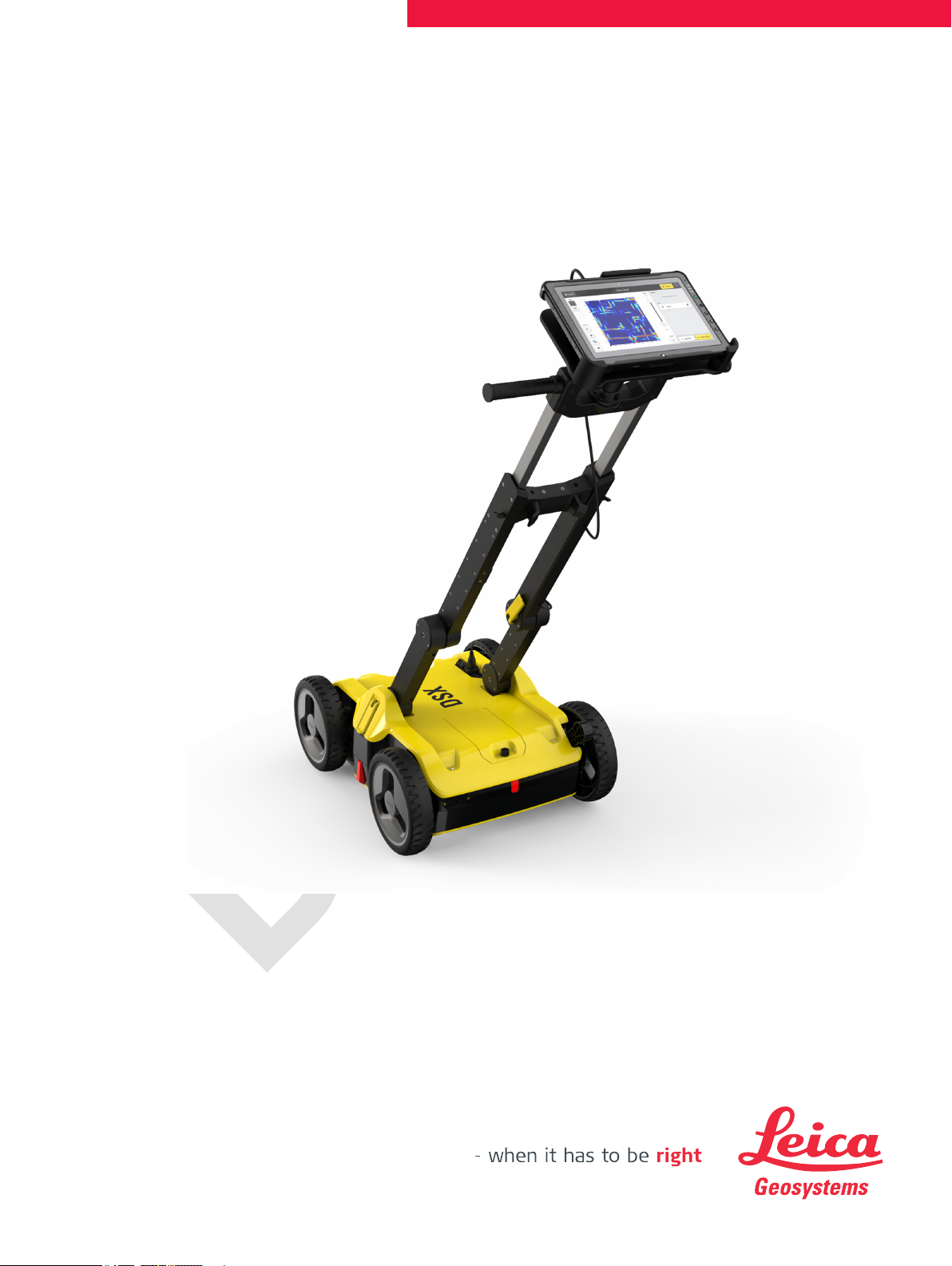
Leica DSX
User Manual
Version 1.0
English
Introduction
Purchase
Product identication
Product identication
Trademarks
Available documentation
Congratulations on the purchase of the Leica DSX.
This manual contains important safety directions as well as instructions for
setting up the product and operating it. Refer to "1 Safety Directions" for further information.
Read carefully through the User Manual before you switch on the product.
The model and serial number of your product are indicated on the type plate.
Always refer to this information when you need to contact your agency or
Leica Geosystems authorised service centre.
This manual applies to the DSX instruments.
Differences between the versions are marked and described.
Windows is a registered trademark of Microsoft Corporation in the United
•
States and other countries
Google is a registered trademark of Google Inc.
•
All other trademarks are the property of their respective owners.
Name Description/Format
Leica Geosystems
address book
DSX User Manual To operate the instrument to a basic
level all instructions required, are included in the User Manual. Provides an
overview of the instrument together
with technical data and safety directions.
DSX Quick Guide Short introduction for setting up the
DSX.
Refer to the following resources for all DSX documentation/software:
the Leica USB stick
•
https://myworld.leica-geosystems.com
•
On the last page of this manual, you can nd the address of Leica Geosystems
headquarters. For a list of regional contacts, please visit
http://leica-geosystems.com/contact-us/sales_support.
myWorld@Leica Geosystems (https://myworld.leica-geosystems.com)
offers a wide range of services, information and training material.
With direct access to myWorld, you are able to access all relevant services
whenever it is convenient for you.
–
ü ü
ü
2

Service Description
myProducts Add all products that you and your company own
and explore your world of Leica Geosystems: View
detailed information on your products and update
your products with the latest software and keep upto-date with the latest documentation.
myService View the current service status and full service his-
tory of your products in Leica Geosystems service
centres. Access detailed information on the services
performed and download your latest calibration certicates and service reports.
mySupport Create new support requests for your products that
will be answered by your local Leica Geosystems
Support Team. View the complete history of your
support requests and view detailed information on
each request in case you want to refer to previous
support requests.
myTraining Enhance your product knowledge with Leica Geosys-
tems Campus - Information, Knowledge, Training.
Study the latest online training material on your
products and register for seminars or courses in
your country.
myTrustedServices Add your subscriptions and manage users for Leica
Geosystems Trusted Services, the secure software
services, that assist you to optimise your workow
and increase your efciency.
3

Table of Contents
1 Safety Directions 5
1.1 General 5
1.2 Denition of Use 6
1.3 Limits of Use 6
1.4 Responsibilities 6
1.5 Hazards of Use 7
1.6 Electromagnetic Compatibility (EMC) 12
1.7 FCC Statement, Applicable in U.S. 13
1.8 Requirements of RSS-220 for Ground Antennas (EN/FR), Applicable in Canada 15
2 Description of the System 16
2.1 General 16
2.2 System Components 16
2.3 Delivery Contents 16
2.4 DSX Components 17
2.5 Accessories 18
2.6 General Battery Handling 18
2.7 Requirements for Using a GNSS Antenna with the DSX 19
3 Setup 20
3.1 Unfolding and Adjusting the Handle 20
3.2 Attaching and Connecting the Laptop or Tablet 20
3.3 Inserting the Battery 21
3.4 Mounting the Pole Support (Surveyor Kit Only) 22
3.5 Switching the DSX ON/OFF 22
3.6 Calibrating the Encoders 23
4 Software 24
4.1 Software Installation 24
4.2 Main Menu 24
4.3 Acquisition of Scan Data 24
4.3.1 The Acquisition Screen 24
4.4 Review of Scan Data 24
4.4.1 The Review Acquisition Screen 24
4.5 Export of Scan Data 24
4.6 Settings 24
5 Planning a Survey 25
6 Procedures for Working with the DSX 26
6.1 Preparing an Acquisition 26
6.2 Marking Out Targets on-Site 26
6.3 Mapping Utilities without Using GPS 27
6.4 Mapping Utilities Using GPS 28
7 Care and Transport 30
7.1 Transport 30
7.2 Storage 30
7.3 Cleaning and Drying 30
8 Technical Data 32
8.1 General 32
8.2 Conformity to European Regulations 33
9 Software Licence Agreement 34
4 Table of Contents
1 Safety Directions
1.1 General
Description
About warning
messages
The following directions enable the person responsible for the product, and
the person who actually uses the equipment, to anticipate and avoid operational hazards.
The person responsible for the product must ensure that all users understand
these directions and adhere to them.
Warning messages are an essential part of the safety concept of the instrument. They appear wherever hazards or hazardous situations can occur.
Warning messages...
make the user alert about direct and indirect hazards concerning the use
•
of the product.
contain general rules of behaviour.
•
For the users‘ safety, all safety instructions and safety messages shall be
strictly observed and followed! Therefore, the manual must always be available
to all persons performing any tasks described here.
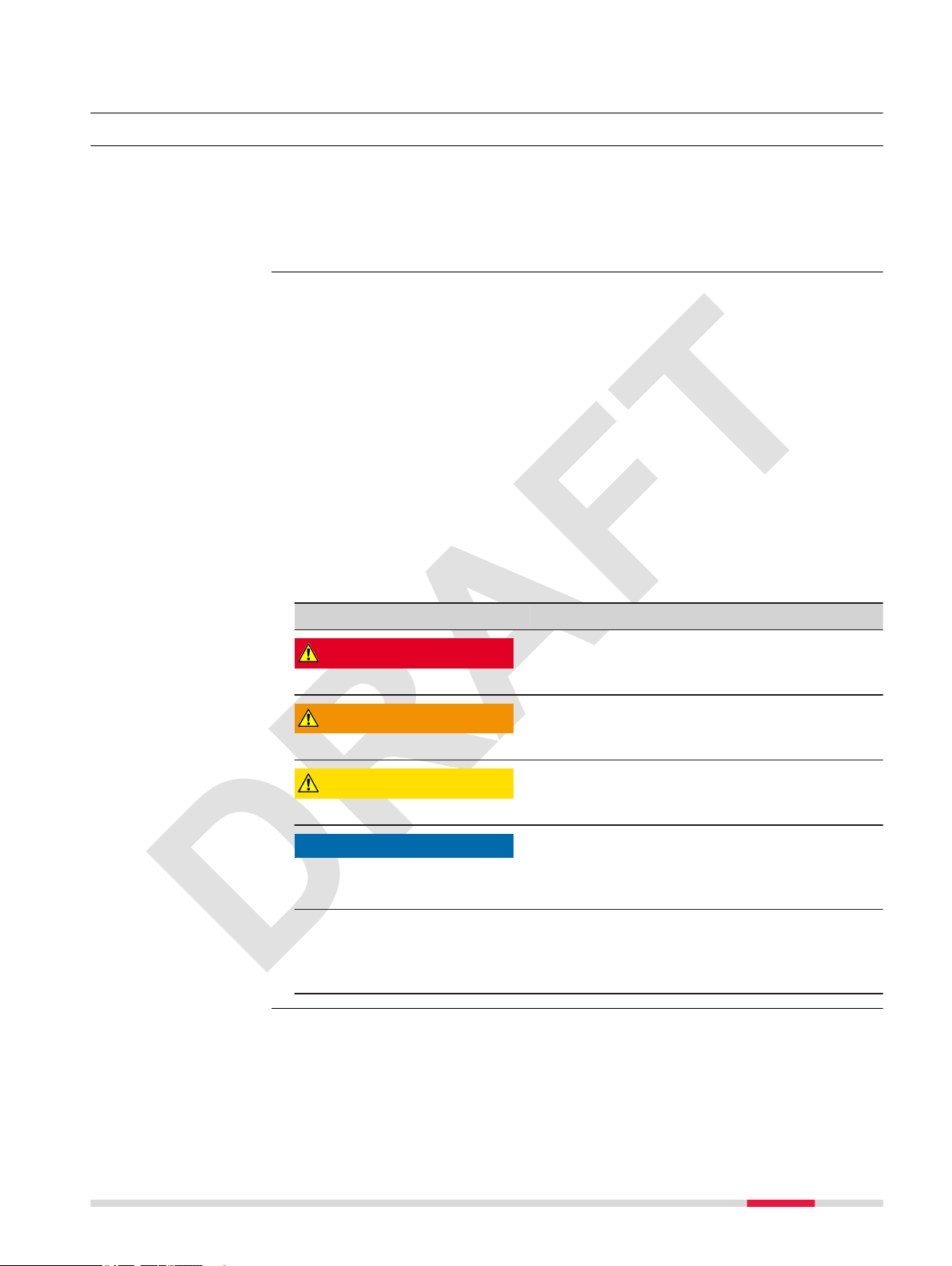
DANGER, WARNING, CAUTION and NOTICE are standardised signal words for
identifying levels of hazards and risks related to personal injury and property
damage. For your safety, it is important to read and fully understand the following table with the different signal words and their denitions! Supplementary safety information symbols may be placed within a warning message as
well as supplementary text.
Type Description
DANGER
WARNING
CAUTION
NOTICE
☞
Indicates an imminently hazardous situation
which, if not avoided, will result in death or
serious injury.
Indicates a potentially hazardous situation or
an unintended use which, if not avoided,
could result in death or serious injury.
Indicates a potentially hazardous situation or
an unintended use which, if not avoided,
may result in minor or moderate injury.
Indicates a potentially hazardous situation or
an unintended use which, if not avoided,
may result in appreciable material, nancial
and environmental damage.
Important paragraphs which must be
adhered to in practice as they enable the
product to be used in a technically correct
and efcient manner.
Safety Directions 5
1.2 Denition of Use
Intended use
Reasonably foreseeable misuse
Data communication with external appliances
•
Carrying out measurement tasks using various GNSS measuring techniques
•
Remote control of product
•
Validating user-input utilities based on the processed data
•
Locating utilities and estimating the depth
•
Detecting both metallic and non-metallic underground utilities
•
Use of the product without instruction.
•
Use outside of the intended use and limits.
•
Disabling safety systems.
•
Removal of hazard notices.
•
Opening the product using tools, for example screwdriver, unless this is
•
permitted for certain functions.
Modication or conversion of the product.
•
Use after misappropriation.
•
Use of products with obvious damages or defects.
•
Use with accessories from other manufacturers without the prior explicit
•
approval of Leica Geosystems.
Inadequate safeguards at the working site.
•
1.3 Limits of Use
Environment
Suitable for use in an atmosphere appropriate for permanent human habitation: not suitable for use in aggressive or explosive environments.
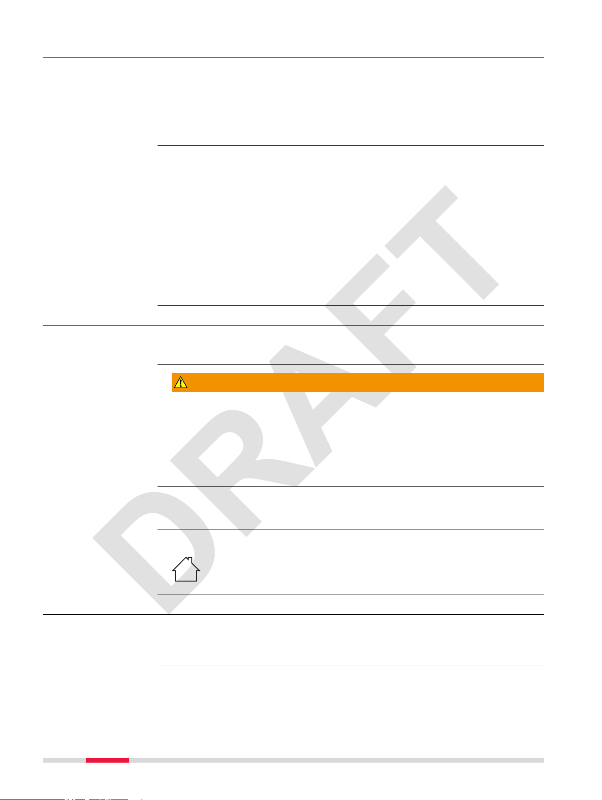
WARNING
Working in hazardous areas, or close to electrical installations or similar situations
Life Risk.
Precautions:
Local safety authorities and safety experts must be contacted by the per-
▶
son responsible for the product before working in such conditions.
☞
Environment
The following advice is only valid for battery charger, power adapter and car
adapter.
Suitable for use in dry environments only and not under adverse conditions.
1.4 Responsibilities
Manufacturer of the
product
Leica Geosystems AG, CH-9435 Heerbrugg, hereinafter referred to as Leica
Geosystems, is responsible for supplying the product, including the User Manual and original accessories, in a safe condition.
6 Safety Directions

Person responsible
for the product
The person responsible for the product has the following duties:
To understand the safety instructions on the product and the instructions
•
in the User Manual.
To ensure that it is used in accordance with the instructions.
•
To be familiar with local regulations relating to safety and accident pre-
•
vention.
To inform Leica Geosystems immediately if the product and the applica-
•
tion becomes unsafe.
To ensure that the national laws, regulations and conditions for the oper-
•
ation of the product are respected.
1.5 Hazards of Use
Exposure to Radio
Frequency (RF) Signals
☞
The product is normally operated at least 1 m away from the user. At a distance of at least 1 m or greater, the typical power density level is below
1 mW/cm2 (0.01 W/m2). This value is far below the level specied by the current regulations.
☞
To ensure that the radio modem is not operated without the permission of
the local authorities on frequencies and/or output power levels other than
those specically reserved and intended for use without a specic permit, the
internal and external radio modems have been designed to operate on frequency ranges and output power ranges. The exact use of the frequency
ranges differs from one region and/or country to another.
When operated in the normal manner of intended use, this product
does not pose health or safety risks regarding radio frequency signals.
NOTICE
Dropping, misusing, modifying, storing the product for long periods or
transporting the product
Watch out for erroneous measurement results.
Precautions:
Periodically carry out test measurements and perform the eld adjust-
▶
ments indicated in the User Manual, particularly after the product has
been subjected to abnormal use as well as before and after important
measurements.
Safety Directions 7
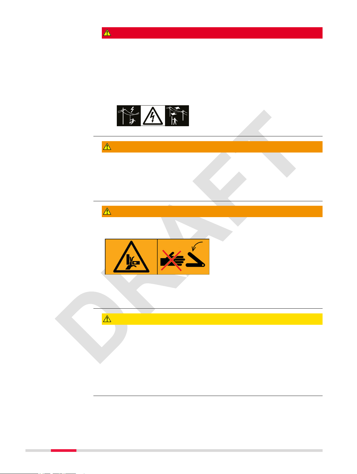
DANGER
Risk of electrocution
Because of the risk of electrocution, it is dangerous to use poles, levelling
staffs and extensions in the vicinity of electrical installations such as power
cables or electrical railways.
Precautions:
Keep at a safe distance from electrical installations. If it is essential to
▶
work in this environment, rst contact the safety authorities responsible
for the electrical installations and follow their instructions.
WARNING
Lightning strike
If the product is used with accessories, for example masts, staffs, poles, you
may increase the risk of being struck by lightning.
Precautions:
Do not use the product in a thunderstorm.
▶
WARNING
Folding the handle
Risk of crushing hands and ngers.
Precautions:
Keep hands and ngers clear from crossing parts when folding handle to
▶
avoid crushing.
CAUTION
Not properly secured accessories
If the accessories used with the product are not properly secured and the
product is subjected to mechanical shock, for example blows or falling, the
product may be damaged or people can sustain injury.
Precautions:
When setting up the product, make sure that the accessories are correctly
▶
adapted, tted, secured, and locked in position.
Avoid subjecting the product to mechanical stress.
▶
8 Safety Directions
WARNING
Inadequate securing of the working site
This can lead to dangerous situations, for example in trafc, on building sites
and at industrial installations.
Precautions:
Always ensure that the working site is adequately secured.
▶
Adhere to the regulations governing safety, accident prevention and road
▶
trafc.
WARNING
Distraction/loss of attention
During dynamic applications, for example stakeout procedures, there is a danger of accidents occurring if the user does not pay attention to the environmental conditions around, for example obstacles, excavations or trafc.
Precautions:
The person responsible for the product must make all users fully aware of
▶
the existing dangers.
WARNING
Unauthorised opening of the product
Either of the following actions may cause you to receive an electric shock:
Touching live components
•
Using the product after incorrect attempts were made to carry out repairs
•
Precautions:
Do not open the product!
▶
Only Leica Geosystems authorised service centres are entitled to repair
▶
these products.
For the AC/DC power supply and the battery charger:
WARNING
Electric shock due to use under wet and severe conditions
If unit becomes wet it may cause you to receive an electric shock.
Precautions:
If the product becomes humid, it must not be used!
▶
Use the product only in dry environments, for example in buildings or
▶
vehicles.
Protect the product against humidity.
▶
Safety Directions 9

For the AC/DC power supply and the battery charger:
WARNING
Unauthorised opening of the product
Either of the following actions may cause you to receive an electric shock:
Touching live components
•
Using the product after incorrect attempts were made to carry out repairs.
•
Precautions:
Do not open the product!
▶
Only Leica Geosystems authorised service centres are entitled to repair
▶
these products.
WARNING
Inappropriate mechanical inuences to batteries
During the transport, shipping or disposal of batteries it is possible for inappropriate mechanical inuences to constitute a re hazard.
Precautions:
Before shipping the product or disposing it, discharge the batteries by the
▶
product until they are at.
When transporting or shipping batteries, the person in charge of the
▶
product must ensure that the applicable national and international rules
and regulations are observed.
Before transportation or shipping, contact your local passenger or freight
▶
transport company.
WARNING
Exposure of batteries to high mechanical stress, high ambient temperatures or immersion into uids
This can cause leakage, re or explosion of the batteries.
Precautions:
Protect the batteries from mechanical inuences and high ambient tem-
▶
peratures. Do not drop or immerse batteries into uids.
WARNING
Short circuit of battery terminals
If battery terminals are short circuited e.g. by coming in contact with jewellery,
keys, metallised paper or other metals, the battery can overheat and cause
injury or re, for example by storing or transporting in pockets.
Precautions:
Make sure that the battery terminals do not come into contact with met-
▶
allic objects.
10 Safety Directions
WARNING
Short circuit of battery
Risk of re, electric shock and damage.
Precautions:
Do not open the battery housing.
▶
Keep away any metallic or wet objects from the battery connectors.
▶
WARNING
Battery pack of the signal transmitter may get hot after prolonged use.
Risk of burning injuries.
Precautions:
Avoid touching the hot battery pack.
▶
Allow the battery pack to cool down before removing it.
▶
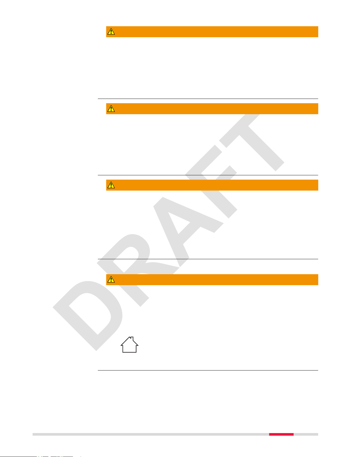
WARNING
Improper disposal
If the product is improperly disposed of, the following can happen:
If polymer parts are burnt, poisonous gases are produced which may
•
impair health.
If batteries are damaged or are heated strongly, they can explode and
•
cause poisoning, burning, corrosion or environmental contamination.
By disposing of the product irresponsibly you may enable unauthorised
•
persons to use it in contravention of the regulations, exposing themselves
and third parties to the risk of severe injury and rendering the environment liable to contamination.
Precautions:
▶
Product-specic treatment and waste management information can be
received from your Leica Geosystems distributor.
The product must not be disposed with household waste.
Dispose of the product appropriately in accordance with
the national regulations in force in your country.
Always prevent access to the product by unauthorised
personnel.
WARNING
Improperly repaired equipment
Risk of injuries to users and equipment destruction due to lack of repair
knowledge.
Precautions:
Only authorised Leica Geosystems Service Centres are entitled to repair
▶
these products.
CAUTION
Before any cleaning procedure, ensure that the instrument is switched off and
the battery has been removed.
Safety Directions 11

CAUTION
Unused connectors must be protected using the attached dust cap.
1.6 Electromagnetic Compatibility (EMC)
Description
The term Electromagnetic Compatibility is taken to mean the capability of the
product to function smoothly in an environment where electromagnetic radiation and electrostatic discharges are present, and without causing electromagnetic disturbances to other equipment.
WARNING
Electromagnetic radiation
Electromagnetic radiation can cause disturbances in other equipment.
Precautions:
Although the product meets the strict regulations and standards which
▶
are in force in this respect, Leica Geosystems cannot completely
exclude the possibility that other equipment may be disturbed.
CAUTION
Use of the product with accessories from other manufacturers. For
example eld computers, personal computers or other electronic equipment, non-standard cables or external batteries
This may cause disturbances in other equipment.
Precautions:
Use only the equipment and accessories recommended by Leica Geosys-
▶
tems.
When combined with the product, they meet the strict requirements
▶
stipulated by the guidelines and standards.
When using computers, two-way radios or other electronic equipment,
▶
pay attention to the information about electromagnetic compatibility provided by the manufacturer.
CAUTION
Intense electromagnetic radiation. For example, near radio transmitters, transponders, two-way radios or diesel generators
Although the product meets the strict regulations and standards which are in
force in this respect, Leica Geosystems cannot completely exclude the possibility that function of the product may be disturbed in such an electromagnetic environment.
Precautions:
Check the plausibility of results obtained under these conditions.
▶
12 Safety Directions

CAUTION
Electromagnetic radiation due to improper connection of cables
If the product is operated with connecting cables attached at only one of their
two ends, for example external supply cables, interface cables, the permitted
level of electromagnetic radiation may be exceeded and the correct functioning of other products may be impaired.
Precautions:
While the product is in use, connecting cables, for example product to
▶
external battery, product to computer, must be connected at both ends.
WARNING
Use of product with radio or digital cellular phone devices
Electromagnetic elds can cause disturbances in other equipment, in installations, in medical devices, for example pacemakers or hearing aids and in aircrafts. Electromagnetic elds can also affect humans and animals.
Precautions:
Although the product meets the strict regulations and standards which
▶
are in force in this respect, Leica Geosystems cannot completely exclude
the possibility that other equipment can be disturbed or that humans or
animals can be affected.
Do not operate the product with radio or digital cellular phone devices in
▶
the vicinity of lling stations or chemical installations, or in other areas
where an explosion hazard exists.
Do not operate the product with radio or digital cellular phone devices
▶
near to medical equipment.
Do not operate the product with radio or digital cellular phone devices in
▶
aircrafts.
Do not operate the product with radio or digital cellular phone devices for
▶
long periods with the product immediately next to your body.
1.7 FCC Statement, Applicable in U.S.
The greyed paragraph below is only applicable for products without
radio.
This device may not cause harmful interference.
This device must accept any interference received, Including interference
that may cause undesired operation.
CAUTION
Do not change or modify this unit without approval by the party responsible for compliance!
FCC ID: RFD-CTDSX
☞
This device complies with part 15 of the FCC Rules.
Operation is subject to the following conditions:
•
•
Changes or modications
Changes or modications to this unit not expressly approved by the party
responsible for compliance could void the user’s authority to operate the
equipment.
▶
Safety Directions 13

Operation of this device is restricted to law enforcement, re and rescue ofcials, scientic research institutes, commercial mining companies, and con-
struction companies. Operation by any other party is a violation of 47 U.S.C. §
301 and could subject the operator to serious legal penalties.
Coordination Requirements:
(a) UWB imaging systems require coordination through the FCC before the
equipment may be used. The operator shall comply with any constraints on
equipment usage resulting from this coordination.
(b) The users of UWB imaging devices shall supply detailed operational areas
to the FCC Ofce of Engineering and Technology who shall coordinate this
information with the Federal Government through the National Telecommunications and Information Administration. The information provided by the UWB
operator shall include the name, address and other pertinent contact information of the user, the desired geographical area of operation, and the FCC ID
number and other nomenclature of the UWB device. This material shall be submitted to the following address:
Frequency Coordination Branch., OET
Federal Communications Commission
445 12th Street, SW
Washington, D.C. 20554
ATTN: UWB Coordination
(c) The manufacturers, or their authorized sales agents, must inform purchasers and users of their systems of the requirement to undertake detailed coordination of operational areas with the FCC prior to the equipment being operated.
(d) Users of authorized, coordinated UWB systems may transfer them to other
qualied users and to different locations upon coordination of change of ownership or location to the FCC and coordination with existing authorized operations.
(e) The NTIA/FCC coordination report shall include any needed constraints that
apply to day-to-day operations. Such constraints could specify prohibited
areas of operations or areas located near authorized radio stations for which
additional coordination is required before operation of the UWB equipment. If
additional local coordination is required, a local coordination contact will be
provided.
(f) The coordination of routine UWB operations shall not take longer than 15
business days from the receipt of the coordination request by NTIA. Special
temporary operations may be handled with an expedited turn-around time
when circumstances warrant. The operation of UWB systems in emergency situations involving the safety of life or property may occur without coordination
provided a notication procedure, similar to that contained in CFR47 Section
2.405(a)-(e), is followed by the UWB equipment user.
CAUTION
Changes or modications not expressly approved by Leica Geosystems for
compliance could void the user's authority to operate the equipment.
14 Safety Directions

0019584_001
Power: 12V 650mA / 7.5W
Leica Geosystems AG
CH-9435 Heerbrugg
Serial No.: XXXXXX
Manufactured: MM.YYYY
Made in GB
Model: DSX
This device complies with part 15 of the FCC Rules. Operation is subject to the
following two conditions:
(1) This device may not cause harmful interference and
(2) this device must accept any interference received, including interference
that may cause undesired operation.
Art.No.:
890000
Contains FCC ID: XXXXXXXXXX IC: XXXXXXXXXX
IP65
Labelling DSX
1.8 Requirements of RSS-220 for Ground Antennas (EN/FR), Applicable in Canada
IMPORTANT NOTE FOR THE CANADIAN CUSTOMERS
Canada Compliance Statement
IC Certication Number: 3177A-CTDSX
This device complies with the requirements of IC Standard RSS-220.
This Ground Penetrating Radar Device shall be operated only when in con-
tact with or within 1 m of the ground.
This Ground Penetrating Radar Device shall be operated only by law
enforcement agencies, scientic research institutes, commercial mining
companies, construction companies, and emergency rescue or reghting
organizations.
NOTE IMPORTANTE POUR LES UTILISATEURS CANADIENS
Canada Compliance Statement
Numéro de certication : 3177A-CTDSX
Cet appareil est conforme aux exigences de la norme RSS IC-220.
Cet équipement géoradar doit être utilisé que lorsqu’il est en contact ou à
moins de 1 mètre du sol.
Cet équipement géoradar doit être utilisé que par des organismes d'applica-
tion de la loi, des instituts de recherche scientique, des sociétés minières
commerciales, des entreprises de construction et de secours d'urgence ou
les organisations de lutte contre les incendies.
CANADIAN REPRESENTATIVE
Company Name : Leica Geosystems Ltd
CN Number : 3177B
Contact Name : Sudha Sachdeva
City : SCARBOROUGH, Ontario M1W3S2
Telephone No : +1 416 497 2463
Email : sudha.sachdeva@leicaus.com
Safety Directions 15

2 Description of the System
0019567_001
a
b
c
2.1 General
Area of application
The DSX system is designed to detect and locate both metallic and non-metallic underground utilities. It provides georeferenced utility maps in survey-grade
accuracy when a supported positioning system is used.
2.2 System Components
DSX System
The DSX system consists of the following components:
a GNSS antenna or Total Positioning
System (TPS)
b Tablet with DXplore software
c DSX utility detection radar
2.3 Delivery Contents
☞
Starter/Surveyor kit
The delivered components depend on the package ordered.
The starter DSX kit includes the following components:
DSX utility detection radar
•
Battery charger with switchable plug heads
•
AC/DC adapter
•
TC1000 tablet cradle
•
Two ram balls with a double socket arm
•
Tightening screws
•
Grid assistance square
•
Leica USB key of DXplore software and the User Manual
•
The surveyor kit will include the starter kit plus one additional component:
Pole support with two brackets and two clamps
•
☞
Other components of the DSX system need to be purchased separately.
16 Description of the System

2.4 DSX Components
0019568_001
g
f
j
h
i
k
a
b
d
e
c
DSX
Description of the
main components
Component Description
Single-frequency
antenna
Control unit The control unit communicates with the positioning
Encoders The encoders are used for measuring the distance
Handle The handle of the DSX can be adjusted both in height
Wheels DSX is using solid rubber tires which do not require
Support tablet The support is designed to hold a Getac CT1000 tablet.
Pole support (surveyor kit only)
The 600 MHz antenna detects underground utilities up
to a depth of 2 m, depending on the soil conditions.
systems, the tablet and the encoders to ensure the
entire system is working together correctly.
travelled from the starting point of a scan. The measured distance is constantly transferred to the control
unit.
The encoders are positioned inside the rear wheels of
the DSX to ensure correct measurements even in
rough terrain, when sometimes only one wheel is
touching the ground.
and inclination. For easy transport of the DSX, the
handle can be folded up.
The LAN cable for connecting to the tablet is by the
right handle
pumping.
The inclination of the support can be adjusted to the
optimal viewing angle.
The pole support includes two clamps and two brackets. Both clamps will be attached to the pole and the
brackets mounted to the handle and housing.
a Cradle for CT1000 tablet sup-
port
b Extendible handle
c Handle extension screws
d Upper hinges for foldable han-
dles
e Wheel lock for cart brake
f Power button for the DSX
g Front alignment marker on the
carrying handle
h Battery compartment
i Encoders – placed inside the
rear wheels
j Bottom hinges for the foldable
handles
k Side alignment markers on the
bottom chassis
Description of the System 17

2.5 Accessories
1 2
3
4
5
6
7
a
0019635_001
Components inside
the accessories bag
Components outside
the accessories bag
2.6 General Battery Handling
a DSX battery
b Charger and plug adapter
c Cradle
d CT1000 charger
e Pole support
f CT1000 tablet
g Accessories bag (symbolised)
a Grid assistance square
☞
Charging the battery
Charging
The permissible temperature range for charging is between 0°C to +40°C/
+32°F to +104°F. For optimal charging, we recommend charging the batteries
at a low ambient temperature of +10°C to +20°C/+50°F to +68°F if possible.
Operation/Discharging
The batteries can be operated from −20 °C to +50 °C/−4 °F to +122 °F.
•
Low operating temperatures reduce the capacity that can be drawn; high
•
operating temperatures reduce the service life of the battery.
Storage
Remove batteries from the product and the charger before storing.
•
After storage recharge batteries before using.
•
Protect batteries from damp and wetness. Wet or damp batteries must be
•
dried before storing or use.
The batteries can be stored from −20 °C to +50 °C/−4 °F to +122 °F.
•
☞
☞
The DSX battery is removable from the battery compartment and is
chargeable.
You cannot turn on the DSX while the battery compartment is empty.
1. Place the battery in the charger and use the appropriate plug head
before charging.
18 Description of the System

0019588_001
2. While charging, the LED of the battery charger lights up orange.
When the battery is nearly charged, the LED turns yellow.
When the battery is fully charged, the LED turns green.
2.7 Requirements for Using a GNSS Antenna with the DSX
Requirements
The DSX can be used with a GNSS antenna to position the radar-scanning data
in an absolute coordinates system and to receive real-time positional corrections while the DSX cart is moving and collecting data.
The antenna should fulll the following requirements:
Multi-frequency (L1 + L2+ L5)
•
Positioning update greater than 5 Hz
•
Bluetooth
•
RTK (Real-Time Kinematic) reference station functionality
•
RTK network
•
Unlimited RTK range
•
DGPS/RTCM
•
☞
For the best result achieved, we recommend using a Variable "x_GS18_T" not
dened. and Leica Variable "x_iCON_gps_70_T" not dened. antenna with tilt
compensation activated
Refer to the equipment list for compatible models.
Description of the System 19

3 Setup
0019569_001
1 2 3
0019586_001
Procedure for setting
up the DSX
The setup procedure of the DSX consists of the following steps:
Unfolding and adjusting the handle (refer to "3.1 Unfolding and Adjusting
•
the Handle")
Inserting the battery (refer to "3.3 Inserting the Battery")
•
Attaching and connecting the CT1000 tablet (refer to "3.2 Attaching and
•
Connecting the Laptop or Tablet")
Mounting the pole support (optional; refer to "3.4 Mounting the Pole Sup-
•
port (Surveyor Kit Only)")
Calibrating the encoders (refer to "3.6 Calibrating the Encoders")
•
3.1 Unfolding and Adjusting the Handle
Unfold and adjust the
handle
1. Unlock the hinges on the inner side of the handles and expand the
handles.
2. When the handles reach the hard-stop, lock the hinges.
3. Unlock another hinges on the outer side of the housing and raise
the handles.
Lock the hinges when the handles are raised to an optimal inclination.
Loosen the screws on both sides to adjust the handle height.
Tighten the screws once the handle height adjustment is done.
3.2 Attaching and Connecting the Laptop or Tablet
Attach and connect
the tablet
☞
The support is designed to hold a CT1000 tablet.
20 Setup

☞
0019587_001
xxxxxx_001
0019637_001
0019570_001
1
2
3
The support includes the tablet cradle to hold the tablet, two RAM
balls (one attached to the cart handles and the other to the cradle).
Also it includes a double socket arm which holds together the RAM
balls.
1. Mount the two RAM balls to attach the tablet to the handle:
One to the handle top
•
The other to the tablet cradle
•
2. Use the double socket arm to hold the two RAM balls:
Adjust the tablet cradle until optimal inclination and then tighten the
screw on the double socket arm.
3.
Plug in the DSX LAN cable to the
tablet.
3.3 Inserting the Battery
Insert the battery
Setup 21

1. To open the battery compartment, loosen the screw on the battery
0019589_001
xxxxxx_001xxxxxx_0010019637_001
compartment.
2. Insert the battery facing downwards. The rough surface of the battery points towards the up-down direction.
3. Close the battery compartment and tighten the screw.
3.4 Mounting the Pole Support (Surveyor Kit Only)
Mount the pole support (surveyor kit
only)
1. Mount the two brackets:
One to the left handle
•
The other to the upper chassis.
•
2. Attach the two clamps to the pole.
3. Make sure the clamps align, so they can both t into the brackets.
Tighten the screws of the clamps, so they are stable on the pole.
4. Place the lower clamp in the housing bracket, and then t the upper
clamp in the handle bracket.
5. Tighten the screw of the handle bracket.
3.5 Switching the DSX ON/OFF
Switch the DSX device
ON/OFF
1. Press the ON/OFF key on the DSX.
22 Setup

3.6 Calibrating the Encoders
Calibration procedure
☞
1. Measure out a distance of at least 10 m. The dened distance is
☞
2. Turn on the control unit of the DSX. Turn on the tablet and start the
3. Start the calibration procedure with the DXplore software. (Refer to
4. Move the DSX along the dened distance.
5. Complete the calibration procedure with the DXplore software and
☞
☞
Calibrate the encoders when using the DSX for the rst time and
when the distance measured by the encoders deviates from the
actual distance.
used as a reference for the calibration procedure.
Ensure that the tablet is connected to the control unit.
DXplore software.
(→ TARGET NOT FOUND) within (→ TARGET NOT FOUND)).
check the calibration result. If necessary, repeat the calibration.
After the prominent part on the outer wheel is worn out, it is
required to perform an encoder calibration. For a separate encoder
calibration, lift one wheel during the calibration procedure, then
repeat the procedure with the other wheel. Compare the results with
the dened distance to ensure that both encoders work properly.
In the DXplore software, a reminder will pop up once the DSX has
been operated for XX meters.
Setup 23

4 Software
4.1 Software Installation
Requirements for
installing the DXplore
software
When purchasing a DSX package that includes a tablet, the DXplore software
is already installed on the tablet.
However, you can also operate the DSX with any laptop/tablet. When installing
the DXplore software on another laptop/tablet, respect the following requirements.
Minimum requirements:
Processor: i3 1.7 GHz
•
RAM: 1 GB
•
Graphic adapter compatible with Open GL 2 or a higher version
•
Operating system: Windows 7
•
Ethernet port
•
Requirements for an optimal performance:
Processor: i5 1.7 GHz
•
RAM: 2 GB
•
Graphic adapter compatible with Open GL 2 or a higher version
•
Operating system: Windows 7
•
Hard disk: 40 GB, shock-proof
•
Serial port (RS232), only necessary, when using a GPS antenna
•
USB port
•
Ethernet port
•
4.2 Main Menu
Available functions
4.3 Acquisition of Scan Data
4.3.1 The Acquisition Screen
4.4 Review of Scan Data
4.4.1 The Review Acquisition Screen
4.5 Export of Scan Data
4.6 Settings
24 Software

5 Planning a Survey
Jobsite Investigation
Jobsite Features
Technical Maps of
existing utilities
To carry out a survey with the DSX in the most efcient way, gather all available information:
Make yourself familiar with the jobsite features.
•
Obtain technical maps about existing utilities on the jobsite.
•
Supplement the acquired scan data by opening manholes onsite.
•
The basic requirement for carrying out a survey is understanding the features
of the jobsite. When gathering information about the jobsite, keep in mind the
objectives of the survey. Consider the following points when preparing the
survey:
Do you need any specic permissions to carry out the survey on the job-
•
site, for example, access permission to pedestrian zones or permission to
interrupt the trafc ow?
Are there any difculties in accessing the jobsite? (Available space, any
•
architectural features forming an obstacle, etc.).
Is the jobsite in an area with a high level of urban trafc, such as streets,
•
squares or pavements? Are there parked cars that could be in the way
during the survey?
Technical maps of existing utilities are normally created by public utility companies. Such maps give a schematic overview about the type and position of
utilities that are constructed and managed by the public utility companies.
Even if these maps are generic, they can give a rst impression of the existing
utilities and provide additional information during the data acquisition and
interpretation phase.
☞
To obtain technical maps of the jobsite, contact the cartographic or
planning ofce of the different utility companies. Clearly specify the
streets and areas of interest. Request the maps early enough in
advance to the survey, to ensure that the maps are available for the
data acquisition phase.
Opening manholes
The following list contains the most important types of utilities that need to
be considered:
Street lights
•
Low, medium and high-voltage electricity cables
•
Telephone cables
•
Gas pipes
•
Water supply pipes
•
Sewage pipes
•
Once the data acquisition is complete, the opening of manholes on site can
provide you with further information regarding depth, diameter and direction
of the utility. This information serves as reference data during the interpretation phase and allows you to estimate the propagation velocity in order to calculate the depth of a utility as precisely as possible.
Planning a Survey 25

6 Procedures for Working with the DSX
6.1 Preparing an Acquisition
Steps to be taken
☞
1. At the jobsite, set up the DSX and mount the accessories, if availa-
2. Depending on the purpose of the survey and the available accesso-
Before departing to the jobsite, ensure that the laptop/tablet and
the DSX battery are fully charged.
ble. Refer to "3 Setup".
ries, carry out one of the procedures described in the following
paragraphs:
Marking out targets on site
•
Mapping utilities without using GPS
•
Mapping utilities using GPS
•
6.2 Marking Out Targets on-Site
Procedure for marking out targets
Follow these steps when the mapping of detected utilities is not necessary.
☞
1. Press the power button to turn on the control unit of the DSX.
2. Turn on the laptop/tablet and start the DXplore.
3. Click the Variable "Button_NewProj" not dened. button.
4.
☞
5. Select the scan direction depending on whether the DSX is being
6. Start the acquisition with the respective acquisition command.
7. When a target is detected, stop and move the DSX back until the
8.
9.
10. When reaching the end of the scan line, stop the acquisition with
Ensure that the spray support is mounted.
Ensure that the laptop/tablet is connected to the control unit.
The software starts calibrating the radar. As soon as the radar calibration is complete, the Acquisition screen is displayed.
Check the radar and battery status. (Refer to (→ TARGET NOT
FOUND) within "4.3.1 The Acquisition Screen").
For a better visualisation of the radargrams, turn off the Map section. (Refer to (→ TARGET NOT FOUND) within "4.3.1 The Acquisition Screen").
pushed or pulled. (Refer to (→ TARGET NOT FOUND) within "4.3.1
The Acquisition Screen").
Position the DSX at the starting point of the line to be scanned.
(Refer to (→ TARGET NOT FOUND) within "4.3.1 The Acquisition
Screen").
Start moving the DSX along the scan line.
vertical yellow line of the radargram is on top of the target.
Insert a marker and estimate the correct depth. (Refer to (→ TAR-
GET NOT FOUND)).
Mark the target on the ground using the spray paint. (Refer to (→
TARGET NOT FOUND) within "4.3.1 The Acquisition Screen").
the respective acquisition command. (Refer to (→ TARGET NOT
FOUND) within "4.3.1 The Acquisition Screen").
26 Procedures for Working with the DSX

11. Position the DSX at the starting point of the next line to be scanned.
Repeat the steps 6 to 10 until the jobsite is covered.
6.3 Mapping Utilities without Using GPS
Procedure for mapping utilities without
GPS
If a GPS antenna is not available, follow these steps to map the detected utilities based on a measurement grid.
☞
1. Press the power button to turn on the control unit of the DSX.
2. Turn on the laptop/tablet and start the DXplore.
3. Click the Variable "Button_NewAssProj" not dened. button.
4. If available, load a map from a saved cartographic le or from the
5.
6. When the setup of the measurement grid is nished, click the Varia-
7.
8. Select the scan direction depending on whether the DSX is being
9. Position the DSX on the line of the measurement grid suggested by
☞
☞
10. Start the acquisition with the respective acquisition command.
11. When a target is detected, stop and move the DSX back until the
12.
13. If the spray support is mounted, mark the target on the ground
14. When reaching the end of the scan line, stop the acquisition with
If available, mount the spray support.
Ensure that the laptop/tablet is connected to the control unit.
The Assisted Project Setup screen is displayed.
internet. (Refer to (→ TARGET NOT FOUND) within "4.3.1 The
Acquisition Screen").
Set up the measurement grid. (Refer to (→ TARGET NOT FOUND)
within (→ TARGET NOT FOUND)).
ble "Button_StartSurvey" not dened. button to start the acquis-
ition.
The software starts calibrating the radar. As soon as the radar calibration is complete, the Acquisition screen is displayed.
Check the radar and battery status. (Refer to (→ TARGET NOT
FOUND) within "4.3.1 The Acquisition Screen").
pushed or pulled. (Refer to (→ TARGET NOT FOUND) within "4.3.1
The Acquisition Screen").
the software.
To skip the line suggested by the software, select a new line.
To edit the starting point position and the scan direction, open the
Starting Point Editor. (Refer to (→ TARGET NOT FOUND) within (→
TARGET NOT FOUND)).
(Refer to (→ TARGET NOT FOUND) within "4.3.1 The Acquisition
Screen").
Start moving the DSX along the scan line.
vertical yellow line of the radargram is on top of the target.
Insert a marker and estimate the correct depth. (Refer to (→ TAR-
GET NOT FOUND)).
using the spray paint. (Refer to (→ TARGET NOT FOUND) within
"4.3.1 The Acquisition Screen").
the respective acquisition command. (Refer to (→ TARGET NOT
FOUND) within "4.3.1 The Acquisition Screen").
Procedures for Working with the DSX 27

15. Repeat the steps 9 to 14 until the measurement grid is covered.
16. Before returning to the main menu, save a report of the survey with
the Survey Report dialogue. (Refer to (→ TARGET NOT FOUND)).
☞
☞
If necessary, you can review the acquired scan data. (Refer to "4.4
Review of Scan Data").
If necessary, you can export the scan data to be edited in AutoCad.
(Refer to "4.5 Export of Scan Data").
6.4 Mapping Utilities Using GPS
Procedure for mapping utilities with GPS
If a GPS antenna is available, follow these steps to create a georeferenced
map of the detected utilities.
☞
1. Press the power button to turn on the control unit of the DSX.
2. Turn on the laptop/tablet and start the DXplore.
3. Select Settings>Survey Settings>Positioning Settings to connect
4. Click the Variable "Button_NewProj" not dened. button.
5.
6. If available, load a map from a saved cartographic le or from the
7. Select the scan direction depending on whether the DSX is being
8. Start the acquisition with the respective acquisition command.
9. When a target is detected, stop and move the DSX back until the
10.
11. If the spray support is mounted, mark the target on the ground
12. When reaching the end of the scan line, stop the acquisition with
If available, mount the spray support.
Mount the GPS support on the DSX and attach the pole with the GPS
antenna.
Ensure that the laptop/tablet is connected to the control unit and to
the antenna.
and congure the GPS. (Refer to (→ TARGET NOT FOUND)).
The software starts calibrating the radar. As soon as the radar calibration is complete, the Acquisition screen is displayed.
Check the radar, GPS and battery status. (Refer to (→ TARGET NOT
FOUND) within "4.3.1 The Acquisition Screen").
internet. (Refer to (→ TARGET NOT FOUND) within "4.3.1 The
Acquisition Screen").
pushed or pulled. (Refer to (→ TARGET NOT FOUND) within "4.3.1
The Acquisition Screen").
Position the DSX at the starting point of the line to be scanned.
(Refer to (→ TARGET NOT FOUND) within "4.3.1 The Acquisition
Screen").
Start moving the DSX along the scan line.
vertical yellow line of the radargram is on top of the target.
Insert a marker and estimate the correct depth. (Refer to (→ TAR-
GET NOT FOUND)).
using the spray paint. (Refer to (→ TARGET NOT FOUND) within
"4.3.1 The Acquisition Screen").
the respective acquisition command. (Refer to (→ TARGET NOT
FOUND) within "4.3.1 The Acquisition Screen").
28 Procedures for Working with the DSX

13. Position the DSX at the starting point of the next line to be scanned.
Repeat the steps 8 to 12 until the jobsite is covered.
14. Before returning to the main menu, save a report of the survey with
the Survey Report dialogue. (Refer to (→ TARGET NOT FOUND)).
☞
☞
If necessary, you can review the acquired scan data. (Refer to "4.4
Review of Scan Data").
If necessary, you can export the scan data to be edited in AutoCad.
(Refer to "4.5 Export of Scan Data").
Procedures for Working with the DSX 29

7 Care and Transport
7.1 Transport
Shipping
Shipping, transport of
batteries
When transporting the product by rail, air or sea, always use the complete
original Leica Geosystems packaging, container and cardboard box, or its
equivalent, to protect against shock and vibration.
When transporting or shipping batteries, the person responsible for the product must ensure that the applicable national and international rules and regulations are observed. Before transportation or shipping, contact your local
passenger or freight transport company.
7.2 Storage
Product
Li-Ion battery
Respect the temperature limits when storing the equipment, particularly in
summer if the equipment is inside a vehicle. Refer to "8 Technical Data" for
information about temperature limits.
• Refer to (→ TARGET NOT FOUND) for information about storage tempera-
ture range.
Remove batteries from the product and the charger before storing.
•
After storage recharge batteries before using.
•
Protect batteries from damp and wetness. Wet or damp batteries must be
•
dried before storing or use.
A storage temperature range of 0°C to +30°C/+32°F to +86°F in a dry
•
environment is recommended to minimise self-discharging of the battery.
At the recommended storage temperature range, batteries containing a
•
40% to 50% charge can be stored for up to one year. After this storage
period the batteries must be recharged.
7.3 Cleaning and Drying
WARNING
Risk of electric shock during cleaning and drying
If the product is turned on during cleaning or drying you may receive an electric shock.
Precautions:
Ensure that all cables are disconnected, including the power supply
•
cable.
Before cleaning the product, turn off the product and all other devi-
•
ces connected to the product.
Ensure that the product is dry before reconnecting cables and turning
•
on the product.
Use only a clean, soft, lint-free cloth for cleaning. If necessary, moisten
the cloth with water or soapy water. Do not use other liquids; these may
attack the product surface.
Product and Accessories
Cables and plugs
▶
•
Keep plugs clean and dry. Blow away any dirt lodged in the plugs of the connecting cables.
30 Care and Transport

caps
Wet connectors must be dry before attaching the dust cap.Connectors with dust
Care and Transport 31

8 Technical Data
0019571_001
309 mm
1041 mm
711 mm
542 mm
562 mm
8.1 General
Dimensions
Weight
Control unit
DSX
DSX – without battery
23 kg
and tablet
Power Consumption 13.3 W
Power Supply 12 V DC, 12 Ah
SLAB (Sealed Lead Acid Battery)
Battery for control
unit
Single-frequency
antenna
Battery for DSX
Data Acquisition
Type Rechargeable SLAB (Sealed Lead Acid Battery)
Voltage 12 V
Capacity 12 Ah
Antenna Footprint 40 cm × 50 cm
Number of Hardware
1
Channels
Antenna Central Fre-
600 MHz
quencies
Antenna Orientation Broadside antenna array in the direction which is
perpendicular to the DSX moving direction
Sampling Frequency 400 kHz
Type Li-Ion
Voltage 14.8 V
Capacity GEB242 5.8 Ah
Typical operating time: Measuring time - 8 h
Acquisition Speed Normal walking speed, up to 7 km/h
32 Technical Data

Scan Rate per Channel
– for 512 Samples per
Scan
Scan Interval 42 scans per metre
Positioning
381 scans per second
Two integrated encoders on the rear wheels
•
GNSS antenna or Total Positioning System
•
(TPS – surveyor kit only)
Environmental speci-
cations
Temperature
Operating temperature [°C] Storage temperature [°C]
-10 to +40 -40 to +70
GEB242:
-10 to +55
Protection against water, dust and sand
Protection
IP65 (IEC 60529)
Humidity
Protection
Max 95% non-condensing
The effects of condensation are to be effectively counteracted by periodically drying out the instrument.
-40 to +70
8.2 Conformity to European Regulations
Conformity to European regulations
The equipment conforms to the following requirements set by EC regulations, including subsequent modications, and to the legislation set by the
member states that implement these regulations:
2014/53/EU Radio Directive
Warning: this equipment is destined for use in industrial environments (Class
A apparatus). In residential, commercial and light industry environments, this
apparatus may generate radio interference: in this case, the user may be
required to operate while taking appropriate countermeasures.
The apparatus is sensitive to the presence of external electromagnetic elds,
which may reduce its performance.
Receiver test according to EN 302 066 v. 2.1.0
The unit has been tested according to the provision of the EN 302 066 v.
2.1.0. Specically, for the receiver test (that tests the inuence of an interferer signal to the device), the following performance criterion has been
used (see ETSI TS 103 361 v.1.1.1) .
Performance criterion: The difference D between the Rx signal noise
(increased by an interferer) and the maximum input signal for the Rx in the
linear region of operation.
Level of performance: D
> 30 dB
min
Technical Data 33

9 Software Licence Agreement
Software Licence
Agreement
This product contains software that is preinstalled on the product, or that is
supplied to you on a data carrier medium, or that can be downloaded by you
online according to prior authorisation from Leica Geosystems. Such software
is protected by copyright and other laws and its use is dened and regulated
by the Leica Geosystems Software Licence Agreement, which covers aspects
such as, but not limited to, Scope of the Licence, Warranty, Intellectual Property Rights, Limitation of Liability, Exclusion of other Assurances, Governing
Law and Place of Jurisdiction. Please make sure, that at any time you fully
comply with the terms and conditions of the Leica Geosystems Software
Licence Agreement.
Such agreement is provided together with all products and can also be referred to and downloaded at the Leica Geosystems home page at
http://leica-geosystems.com/about-us/compliance-standards/legal-documents
or collected from your Leica Geosystems distributor.
You must not install or use the software unless you have read and accepted
the terms and conditions of the Leica Geosystems Software Licence Agreement. Installation or use of the software or any part thereof, is deemed to be
an acceptance of all the terms and conditions of such Licence Agreement. If
you do not agree to all or some of the terms of such Licence Agreement, you
must not download, install or use the software and you must return the
unused software together with its accompanying documentation and the purchase receipt to the distributor from whom you purchased the product within
ten (10) days of purchase to obtain a full refund of the purchase price.
34 Software Licence Agreement


Leica Geosystems AG
Heinrich-Wild-Strasse
CH-9435 Heerbrugg
Switzerland
Phone +41 71 727 31 31
www.leica-geosystems.com
900644-1.0.0en
Original text (900644en-1.0.0)
Published in Switzerland
© 2019 Leica Geosystems AG, Heerbrugg, Switzerland
 Loading...