


User Manual
For CT301
1 INTRODUCTION ................................................................................................................................................... 2
2 ELECTRICAL INTERFACE .................................................................................................................................. 3
2.1 Maximum Ratings ...................................................................................................................................................... 3
2.2 Operating Conditions ................................................................................................................................................. 3
2.3 Connector .................................................................................................................................................................... 3
3 UART CONFIGURATION ..................................................................................................................................... 4
4 MODULE MOUNTING .......................................................................................................................................... 4
5 RADIO MODULE COMMAND SET ...................................................................................................................... 4
6 RADIO MODULE CONFIGURATION ................................................................................................................... 8
6.1 Filter Table.................................................................................................................................................................. 8
6.2 Examples ..................................................................................................................................................................... 9
7 CERTIFICATION ................................................................................................................................................. 10
7.1 FCC Certification ..................................................................................................................................................... 10
7.2 Industry Canada Certification ................................................................................................................................ 10
7.1 Japan Certification ................................................................................................................................................... 10
15.08.2019
CONFIDENTIAL
Date / Editor Version / Comment
08-03-2019 / 4081-BOG Document creation
11-03-2019 / 4081-BOG Update electrical interface, command table, filter table
1 of 10

User Manual
For CT301
1 I
N T R O D UC T I O N
Top
Bottom
15.08.2019
The CT301 radio facilitates a IEEE 802.15.4 based radio communication. It uses a proprietary wireless
communication stack to implement a star or cluster network with multiple nodes communicating simultaneously.
The radio module provides three basic functions:
• Transparent communication between network node and network coordinator
• Writing parameters to the radio module for configuration to determine its mode of operation such as the
configuration of a node or coordinator
• Reading parameters from the radio module
All communication to the radio module is established through a UART communication interface.
2 of 10
User Manual
Rating
Min.
Max.
Unit
Pin
For CT301
2 E
L E C T R I C A L IN T E RF A C E
2.1 Maximum Ratings
Input Voltage VCC -0.3 3.6 V
Input Current VCC 150 mA
Operating Temperature -30 60 °C
2.2 Operating Conditions
Rating Min. Typ Max. Unit
Input Voltage VCC 3.0 3.15 3.3 V
Operating Current RX mode (across temperature and
supply voltage range)
Operating Current TX with CW 18dBm 93 130 175 mA
Operating Current TX with CW 10dBm 46 70 94 mA
Sleep mode current 10 15 25 µA
RF Output Power E.I.R.P USA 18 dBm
RF Output Power E.I.R.P Europa 10 dBm
15.08.2019
15 20.3 30 mA
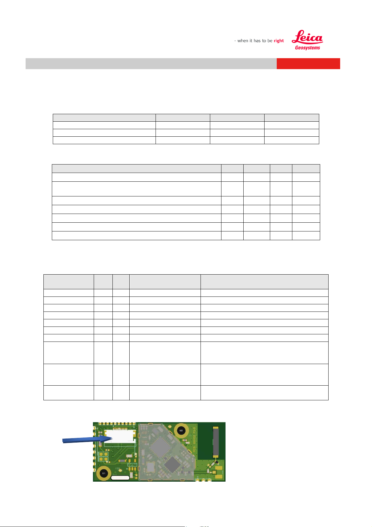
2.3 Connector
The radio module is connected through a 10-pin 0.5mm pitch flat cable on connector J5:
Main function I/O 10-
VCC 1 Power Supply 3 / 3.3 V
VCC 2 Power Supply 3 / 3.3 V
GND 3 Ground
GND 4 Ground
GND 5 Ground
UART TX O/O 6 UART TX (Out) High impedance if in shutdown.
UART RX I/I 7 UART RX (In)l High impedance if in shutdown.
RTS O/I 8 Not used Option SW implemented, wired to
CTS I/I 9 Not Used Option SW implemented, wired to
SHUTDOWN I 10 Enable sleep mode Shutdown or sleep mode, to be able to
The location of connectorJ5 is indicated below. To provide cable relief a slot is integrated into the radio module.
Description Comment
corresponding hardware pin on µC. High
impedance if in shutdown.
corresponding hardware pin on µC. High
impedance if in shutdown
select multiple radio modules
3 of 10

User Manual
31
40
41
2
For CT301
3 U ART C
Baudrate Data Bits Stop bits Parity Flow Control
19200 8 1 No No
4 M
The CT301 radio module can be mounted with two 2.5mm machine screws. It is preferred that the screws and
stand offs are made of non conductive and non-ferromagnetic material such as plastic or ceramics.
Alternatively the module can be directly soldered on to a carrier board utilizing the radio module using connector J3
and J5.
5 R
The following table lists all commands available to the user through the UART communication.
O D U LE MO U N T I N G
AD I O MO D U LE CO M M AN D SE T
O N F I G U R AT I O N
15.08.2019
Ref
LF or CR/LF 0/READY
------ 0/UNKNOWN
------ 0/MISSING
n/_____ nothing
45
nnnn/_____ nothing
46
0/TEST/CW/hh 0/OK
1
0/TEST/RND/hh 0/OK
0/TEST/DUTY/hh 0/OK
3
0/TEST/CH/hh 0/OK
4
0/TEST/LOOP 0/OK
5
0/TEST/END 0/OK
6
4 of 10
Command Response Remark
May be used to wake up from sleep mode.
Unknown command for device 0.
This command is missing or not implemented
Normal addressing can be used to send data to a
Chameleon device. 1 - 63 data bytes may be appended.
N is the address of the Filter n paired to the other
device. The address n is 1 hex digit.
The address n=0 is the own address of the device
Extended addressing can be used to send data to a
specific WPS address. The address specifier has to
consist of 4 hex digits.
TEST commands
Generate CW Signal for Test with TX power of 0-n dBm.
0/ERR
0/ERR
0/ERR
0/ERR
0/ERR
Test function for EMV measurement.
Generate random Signal for Test with TX power of hh
dBm. Test function for EMV measurement.
Set ‘ON’ time in ms for test signal. Total duty cycle
period is 100ms. Minimum is 10 (0A). Maximum is 100
(64).
Force module to channel 0xhh. Can be used during
regular operation (however in that case the WPS stack
may change it at any time).
Enable / disable UART Loop back. All commands are still
processed.
Finish any test mode. An error is generated if no test
signal is active.

User Manual
8
11
75
15
17
19
22
24
For CT301
0/TEST/HIST/OK 0/OK
7
0/TEST/VER 0/VER/hhhhhhhh/
hhhhhhhh
0/TEST/BUILD Not defined
9
0/TEST/INFO Not defined
10
0/TEST/RX 0/RX/hh
0/TEST/RESET 0/BOOTING
68
0/READY
0/TEST/TXIP/hhhh 0/OK
74
0/TXIP/hhhh
0/TEST/TXIP 0/TXIP/hhhh
0/STAT/RX/n 0/RX/n/hh
13
0/STAT/PER/n 0/PER/hhhhhhhh
14
0/STAT/RPER 0/OK
15.08.2019
Assertion history is always empty.
Not supported anymore.
Get version number of SW and WPS (High word/Low
word).
For debug purposes. Returns build and revision
information.
For debug purposes (may scan all selected channels
and return dBm)
Get current RX level hh dBm. Works only if no TX test
mode is active.
Reboot the system.
Set the TX power direct (msbs: 0-5 IB25, 6-7 PA, 8-15
tempCoeff (IB = IB25 + (T -25) *TempCoeff / 512).To
bring the system back to regular mode, the value must
be set to 0 or the Radio device must be restarted.
Get the direct TX power setting.
Status commands
Get receive strength in dBm of last LiveLine frame from
device n, so do enable LL mechanism
Get Packet error rate of connection to device n
(incremented on WPS_NO_LINK events only)
Reset all Packet error rate counters
0/STAT/INFO 0/INFO/hhhhhhhh
16
0/STAT/CH 0/CH/hh
0/STAT/SLEEP 0/SLEEP
18
Configuration commands
0/CONF/FTR/n/hhhhhhhh 0/OK
0/ERR
0/CONF/FTR/n 0/FTR/n/hhhhhhh
20
h
0/CONF/TXP/hh 0/OK
21
0/ERR
0/CONF/TXP 0/TXP/hh
0/CONF/DEV/n 0/DEV/n/none
23
0/DEV/n/hhhh
0/CONF/CH/hhhh 0/OK
Get radio module info (power)
0x00000000 = maximum possible tx power in dBm.
0x00000000 = minimum possible tx power in dBm
Get current channel.
Radio module is forced to sleep as soon as the WPS is
idle.
Set filter value 0xhhhhhhhh for filter /
address n. Also used to configure the role radio module
itself (with n = 0).
For n=0 the filter could not set to 00000000
Get filter value
Set power-limit in dBm. Value out of possible range will
be truncated into the range.
Range for CT301 (0x00 – 0x16) dBm.
Get. Max Power in dBm (may be truncated)
Get WPS address of device that is paired on filter
structure n.
FFFF means no configuration
Set allowed channel with bitmask hhhh. LSB = channel
5 of 10

User Manual
25
69
34
For CT301
0/ERR
0/CONF/CH 0/CH/hhhh
0/CONF/LL/n 0/OK
26
0/ERR
0/CONF/RSTLL 0/OK
27
0/ERR
0/CONF/BAUD/x 0/OK
28
0/ERR
0/CONF/TIMLL/hh 0/OK
29
0/ERR
0/CONF/GAIN/h 0/OK
30
0/ERR
0/CONF/PANID 0/PANID/hhhh
0/CONF/REFORMAT 0/BOOTING
73
0/READY
11. MSB = channel 26. On a laser it triggers the search
for the quietest channel.
Get allowed channel bitmask.
Set Live Line target to filter n. Setting is stored in Flash.
Reset any set LL target. Setting is stored in Flash.
Sets the baud rate. Value is hex. The baud rate is
changed immediately after the response 0/OK is sent.
Both communication partners shall make a 2.5ms
pause after 0/OK was transmitted to give the partner
time to reconfigure.
Set Live Line repetition time, value is in hex, with 10ms
resolution.
Set the LNA gain of the PA on the 300m Radio h=0: low
gain; h=1: high gain
Get the random PanId. Not Implemented.
Initialize the nonvolatile data and restart.
15.08.2019
Pairing commands
0/PAIR/START 0/OK
32
0/ERR
0/PAIR/ALLOW 0/OK
33
0/ERR
0/PAIR/STOP 0/OK
0/ERR
0/PAIR/NETLIST 0/OK
47
0/ERR
0/PAIR/ELEMENT 0/ELEMENT/id,s
72
0/ERR
Start pairing with new network (only for Remote /
Receiver).
Allow pairing of new device (only for
coordinator/Laser).
Stop pairing for new devices (only for
coordinator/Laser).
Discover all lasers/coordinators by PAN ID. Only the
lasers supporting this feature are answering to it. The
list may contain max. 32 devices, sorted by signal
strength (strongest first) and can be read by
0/PAIR/ELEMENT command.
The command needs always the same time to check all
channels (the request is repeated a few times on each
channel).
Command does not unpair the current connection, but
the live line transmission shall be disabled before
calling NETLIST.
Reads one entry at a time from discovery list
(generated by 0/PAIR/NETLIST command).
The id is the 16bit PAN ID of the laser. s is the signal
strength.
When all devices were read the response is 0/ERR.
Same if no devices were found. The list can be read only
once.
6 of 10

User Manual
35
37
38
39
42
71
70
43
For CT301
0/PAIR/SELECT/id/hhhh
48
0/PAIR/SELECT/id
0/OK
0/ERR
0/PAIR/UNSELECT
0/PAIR/CONFIRM 0/OK
49
0/ERR
0/PAIR/ID 0/ID/id
73
0/ERR
0/LOST/n
0/FOUND/n
36
0/CHSWITCH/hh
Selects a laser. The id is the PAN ID of the laser. OK is
only a immediate acknowledge. hhhh is a optional user
value transmitted to laser. Command also enables the
visual feedback on laser (by a periodic request every
0.5s). For keeping visual feedback the sleep of the node
must be prevented by a “\n” or by repeating the
command. The visual feedback is disabled on: sleep,
any other command from host, UNSELECT command.
Command does not unpair the current connection, but
the live line transmission shall be disabled before.
Start pairing sequence with laser device, previously
selected by SELECT command. It is stored to NV
memory (exactly the same as regular pairing). The
previous connection is lost. On successful pairing the
message 0/PAIR/n is shown on coordinator/laser.
Returns the 16bit PAN ID of the paired device (paired by
0/PAIR/START or 0/PAIR/CONFIRM). 0/ERR if not
paired.
Asynchrony commands
Live line connection lost with device, that is paired to
filter n.
Live line connection reestablished with device, that is
paired to filter n.
Radio switched to new channel (only in debug mode)
15.08.2019
0/OK
0/FAIL/n
0/PAIR/n
0/NETLIST_ACK
0/SELECTED/hhhh
0/UNSELECTED
0/SELECT_ACK
70
0/SELECT_LOST
0/READY
0/WPS/hhhh
44
0/WPS/hhhhhhhh
Send data successful.
Send data failed.
Paired new Device to filter n.
Asynchronous response after 0/PAIR/NETLIST
command, which always needs the same time to
complete the search (ca. 200ms default).
request for (visual) feedback on coordinator. hhhh is a
user value from application of node. Laser application
does not need a timeout for selection: a 0/UNSELECTED
will always come after a timeout.
messages on node/combo during (visual) feedback. An
initial SELECT_ACK is sent on the first acknowledge
from coordinator/laser. SELECT_LOST is sent if the
coordinator does not acknowledge anymore (to the
periodic request from node). And ACK again if the
coordinator is responding again.
The radio module is ready to receive data via UART or
transceiver after sleep mode or power-up.
The WPS crashed. This event occurs twice.
The first error gives the file number and the second
gives the line nr that caused the crash.
7 of 10

User Manual
Type/ Bit range
Bitmask
Value
Remark
31 0/1 Leica Device
30 0 Reserved
29 0 Reserved
28 0 Reserved
27 0 Reserved
26 0 Reserved
25 0 Reserved
24 0 Reserved
0x11
Laser
0x12
Remote
0x13
Receiver
0x14
USB stick
0x15
Remote (RC800)
0x16
Combo Control
0x17...0xFE
Reserved
0xFF All devices
15-14 (2 bit)
15 0/1 X-Axis
13 1 Reserved
12 0/1 300m
11 0/1 100m
10-4 (7 bit)
3-0 (4 bit)
0x0..0xE
Device Number
0xF All device number allowed
For CT301
6 R
The radio module can be configured through filters using the command 0/CONF/FTR/n/hhhhhhhh, whereas
n indicates the filter number and h the filter bit mask. Each filter corresponds to a node in the network where as
filter 0 is reserved for the radio module configuration. Each bit in the mask has a dedicated function:
AD I O MO D U LE CO N F IG U R AT I O N
15.08.2019
6.1 Filter Table
Manufacturer Type
31-24 (8 bit)
Device Type
23-16 (8 bit)
Axis Type
Range Type
13-11 (3 bit)
Reserved
Device Number
14 0/1 Y-Axis
0x7F Reserved
8 of 10

User Manual
For CT301
15.08.2019
6.2 Examples
Configuration of Combo Control
0/CONF/FTR/0/8016D00F<CR><LF> // Leica Combo Control 300 /x/y all devices allowed
0/CONF/FTR/1/8011D80F<CR><LF> // Leica Laser filter 100 /300 /x/y all devices allowed
Configuration of Laser
0/CONF/FTR/0/8011D80F<CR><LF> // Leica Laser Device
0/CONF/FTR/1/8016D00F<CR><LF> // Leica Combo Control filter 300 /x/y
0/CONF/FTR/2/8016D00F<CR><LF> // Leica Combo Control filter 300 /x/y
0/CONF/FTR/3/8016D00F<CR><LF> // Leica Combo Control filter 300 /x/y
Pairing allowed on laser
0/PAIR/ALLOW<LF>
Pairing of Receiver
0/PAIR/START<LF>
Pairing of Remote
0/PAIR/START<LF>
Pairing Stop
0/PAIR/Stop<LF>
Send Data from Combo Control to Laser
1/set/23/34<LF>
Get all reachable devices
0/NETLIST<LF>
<- 0/NETLIST_ACK<LF>
0/PAIR/ELEMENT<LF>
<- 0/ELEMENT/426A,64<LF>
0/PAIR/ELEMENT<LF>
<- 0/ELEMENT/246E,54<LF>
0/PAIR/ELEMENT<LF>
<- 0/ERR // no other devices
Pairing initiated by Combo device
0/PAIR/SELECT/426a/1<LF> // PanId Laser=426a, 1 is the indication for the Laser to start pairing
<- 0/OK<LF>
<- 0/SELECT_ACK<LF>
0/PAIR/CONFIRM<LF>
<- 0/OK<LF>
9 of 10

User Manual
For CT301
7 C
E R T I F I C AT I O N
15.08.2019
7.1 FCC Certification
This device complies with Part 15 of the FCC Rules. Operation is subject to the following two
conditions: (1) this device may not cause harmful interference, and (2) this device must accept
any interference that may cause undesired operation.
If using a permanently affixed label, the modular transmitter must be labeled with its own FCC identification
number, and, if the FCC identification number is not visible when the module is installed inside another device, then
the outside of the device into which the module is installed must also display a label referring to the enclosed
module. This exterior label can use wording such as the following: “Contains Transmitter Module FCC ID: RFDCT301” or “Contains FCC ID: RFD-CT301”. Any similar wording that expresses the same meaning may be used.
The Grantee may either provide such a label, an example of which must be included in the application for
equipment authorization, or, must provide adequate instructions along with the module which explain this
requirement. In the latter case, a copy of these instructions must be included in the application for equipment
authorization.
Installers must be provided with antenna installation instructions and transmitter operating conditions for satisfying
RF exposure compliance.
7.2 Industry Canada Certification
This device complies with Industry Canada licence-exempt RSS standard(s). Operation is subject to the following
two conditions: (1) this device may not cause harmful interference, and (2) this device must accept
any interference, including interference that may cause undesired operation of the device.
Cet équipement est conforme du réglement de la Industry Canada.
(1) l’appareil ne doit pas générer d’interférences nuisibles et (2) doit accepter toutes interférences y compris celles
pouvant provoquer un fonctionnement indésirable.
The Industry Canada certification label of a module shall be clearly visible at all times when installed in the host
device, otherwise the host device must be labelled to display the Industry Canada certification number of the
module, preceded by the words “Contains transmitter module”, or the word “Contains”, or similar wording
expressing the same meaning as follows:
Contains transmitter module IC: 3177A-CT301
7.1 Japan Certification
Japanese Radio Law and Japanese Telecommunications Business Law Compliance.
This device has been granted a designation number by Ministry of Internal Affairs and Communications under
„Ordinance concerning Technical Regulations Conformity Certification etc. of Specified Radio Equipment
(特定無線設備の技術基準適合証明等に関する規則)“ Article 2-1-19.
“This device should not be modified (otherwise the granted designation number will be invalid)“
R:202-LSF027
10 of 10
 Loading...