

Page 1

User Manual
For CT300
1 INTRODUCTION ...................................................................................................................................................2
2 ELECTRICAL INTERFACE ..................................................................................................................................3
2.1 Maximum Ratings ...................................................................................................................................................... 3
2.2 Operating Conditions................................................................................................................................................. 3
2.3 Connector.................................................................................................................................................................... 3
3 UART CONFIGURATION .....................................................................................................................................4
4 MODULE MOUNTING ..........................................................................................................................................4
5 RADIO MODULE COMMAND SET ......................................................................................................................5
6 RADIO MODULE CONFIGURATION...................................................................................................................7
7 CERTIFICATION ...................................................................................................................................................8
7.1 FCC Certification ....................................................................................................................................................... 8
26. Sep. 2012
CONFIDENTIAL
Date / Editor Version / Comment
26-SEPT-2012 / WMART Document creation
1 of 8
Page 2

User Manual
For CT300
1 I
NT RO DUC TI ON
The CT300 radio facilitates a IEEE 802.15.4 based
radio communication. It uses a proprietary wireless
communication stack to implement a star or cluster
network with multiple nodes communicating
simultaneously.
The radio module provides three basic functions:
- Transparent communication between network node and network coordinator
- Writing parameters to the radio module for configuration to determine its mode of operation such as the
configuration of a node or coordinator
- Reading parameters from the radio module
All communication to the radio module is established through a UART communication interface.
26. Sep. 2012
2 of 8
Page 3
User Manual
For CT300
2 E
LE CT RIC AL INT ER FA CE
26. Sep. 2012
2.1 Maximum Ratings
Rating Min. Max. Unit
Input Voltage VCC -0.3 3.6 V
Input Current VCC 150 mA
Operating Temperature -30 60 °C
2.2 Operating Conditions
Rating Min. Typ Max. Unit
Input Voltage VCC 2.1 3 / 3.3 3.6 V
Operating Current at 3dBm - 30 - mA
Maximum RF Output Power 7 dBm
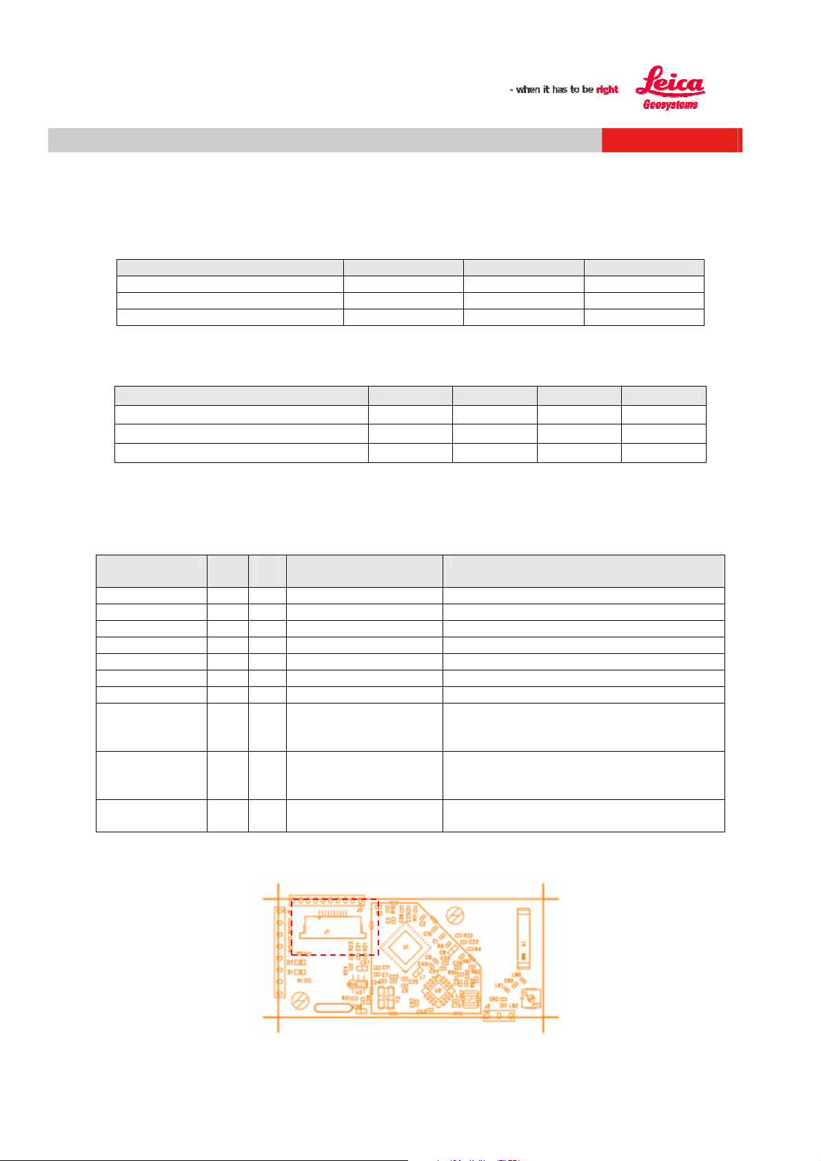
2.3 Connector
The radio module is connected through a 10-pin 0.5mm pitch flat cable on connector J1:
Main function I/O 10-
VCC 1 Power Supply 3 / 3.3 V
VCC 2 Power Supply 3 / 3.3 V
GND 3 Ground
GND 4 Ground
GND 5 Ground
UART TX O/O 6 UART TX (Out) High impedance if in shutdown.
UART RX I/I 7 UART RX (In)l High impedance if in shutdown.
RTS O/I 8 Not used Option SW implemented, wired to
CTS I/I 9 Not Used Option SW implemented, wired to
SHUTDOWN I 10 Enable sleep mode Shutdown or sleep mode, to be able to
The location of connectorJ1 is indicated below. To provide cable relief a slot is integrated into the radio module.
Description Comment
Pin
corresponding hardware pin on uC. High
impedance if in shutdown.
corresponding hardware pin on uC. High
impedance if in shutdown
select multiple radio modules
3 of 8
Page 4

User Manual
For CT300
3 UART C
Baudrate Data Bits Stop bits Parity Flow Control
19200 8 1 No No
4 M
The CT300 radio module can be mounted with two 2.5mm machine screws. It is preferred that the screws and
stand offs are made of a non conductive and non-ferromagnetic material such as plastic or ceramics.
Alternatively the module can be directly soldered on to a carrier board utilizing the radio module using connector J2
and J6.
OD UL E MOU NT I NG
ON FI GU RAT IO N
26. Sep. 2012
4 of 8
Page 5

User Manual
For CT300
5 R
The following table lists all commands available to the user through the UART communication.
5 of 8
AD IO MOD UL E COM MA ND SET
Ref. Group Command Response
1 0/TEST/CW/n 0/OK
2 0/TEST/RND/n 0/OK
0/TEST/DUTY/hh 0/OK
3 0/TEST/CH/n 0/OK
4 0/TEST/LOOP 0/OK Enable / disable UART Loop back
5 0/TEST/END 0/OK
6 0/TEST/HIST 0/Assert: hhhh
7 0/TEST/VER 0/VER/hhhhhhhh/
8 0/TEST/BUILD Not defined For debug purposes. Returns build
9 0/TEST/INFO Not defined For debug purposes
10
11 0/TEST/FREQ 0/OK
12 0/STAT/RX/n 0/RX/n/nn Get Rx Level of last frame from
13 0/STAT/PER/n 0/PER/hhhhhhhh Get Packet error rate of connection
14 0/STAT/RPER 0/OK Reset all Packet error rate counters
15 0/STAT/INFO 0/INFO/hhhhhhhh
16 0/STAT/CH 0/CH/hhhh Get current channel
17
18
19 0/CONF/FTR/n/hhhhhh
20 0/CONF/FTR/n/ 0/FTR/n/hhhhhhhh Get filter value
21 0/CONF/TXP/xx 0/OK
22
Test
0/TEST/RX 0/RX/hh Get current RX level
State
0/STAT/SLEEP 0/OK
Config
hh
0/CONF/TXP 0/TXP/xx Get. Max Power
0/ERR
0/ERR
0/ERR
0/ERR
0/ERR
0/Assert:
HHHH/HHHHHHHH
0/Assert: hhhh
0/Assert:
HHHH/HHHHHHHH
….
hhhhhhhh
0/ERR
0/ERR
0/OK
0/ERR
0/ERR
Generate CW Signal for Test with TX
power of n-0x80 dBm. Test function
for EMV measurement
Generate random Signal for Test with
TX power of n-0x80 dBm. Test
function for EMV measurement
Set ‘ON’ time in ms for test signal.
Total duty cycle period is 100ms.
Minimum is 10 (0x0A). Maximum is
100 (0x64)
Force module to channel n
Finish any test mode. An error is
generated if no test signal is active.
Get Assert-History
hhhh: Assert counter (hex)
HHHH: file number
HHHHHHHH: Line number
Get VersionNumber of SW and WPS
(High word/Low word)
and revision information
Output a frequency signal to verify
internal frequency. The uC must be
reset after this command.
device n. P= nn-0x80 dBm
to device n
Get radio module info (mode, power,
type, )
The lowest 8 bits are the maximum tx
power in dBm + 0x80
Radio module is forced to sleep as
soon as the WPS is idle.
Set filter value 0xhhhhhhhh for filter /
address n. Also used to configure the
radio module itself ( with n = 0)
Set power-limit in dBm
any value that is in physically
possible range is allowed
26. Sep. 2012
Page 6

User Manual
For CT300
23 0/CONF/DEV/n 0/DEV/n/none
24 0/CONF/CH/hhhh 0/OK
25 0/CONF/CH 0/TXP/hhhh Get allowed channel bitmask
26 0/CONF/LL/n 0/OK
27 0/CONF/RSTLL 0/OK
28 0/CONF/BAUD/x 0/OK
29 0/CONF/TIMLL/x 0/OK
30 0/CONF/GAIN/h 0/OK
31
32 0/PAIR/START 0/OK
33 0/PAIR/ALLOW 0/OK
34
35 --- 0/LOST/n Live line connection lost with device,
36 0/FOUND/n Live line connection reestablished
37 --- 0/CH/hh Radio switched to new channel
38 --- 0/OK Send data successful
39 --- 0/FAIL/n Send data failed
40 0/UNKNOWN Unknown command for device 0
41 0/MISSING This command is missing/ not
42 --- 0/PAIR/n Paired new Device to filter n
43 --- 0/READY The radio module is ready to receive
44
45 norm.
46 Ext.
0/DEV/n/hhhh
0/ERR
0/ERR
0/ERR
0/ERR
0/ERR
0/ERR
CR/LF 0/READY May be used to wake up from sleep
Pairing
0/ERR
0/ERR
0/PAIR/STOP 0/OK
0/ERR
Events
--- 0/WPS/hhhh
0/WPS/hhhhhhhh
n/_____ nothing Normal addressing can be used to
addr.
nnnn/_____ nothing
addr.
Get WPS address of device that is
paired on filter structure n
Set allowed channel with bitmask
0xhhhh
Set Live Line target to filter n. Setting
is stored in Flash
Reset any set LL target. Setting is
stored in Flash
Response is sent with old baud rate.
Baud rate must be given in hex.
Set Live Line repetition time to x. x
=1 means 10ms.
Set the LNA gain of the PA on the
300m Radio h=0: low gain; h=1: high
gain
mode
Start pairing with new network (only
for Remote / Receiver)
Allow pairing of new device (only for
coordinator/Laser)
Stop pairing for new devices (only for
coordinator/Laser)
that is paired to filter n
with device, that is paired to filter n
implemented
data via UART or transceiver after
sleep mode or power-up.
The WPS crashed. This event occurs
twice.
The first error gives the file number
and the second gives the line nr that
caused the crash.
send data to a Viper device that is
paired to a filter structure. The
address specifier has to consist of 1
hex digit.
Extended addressing can be used to
send data to a specific WPS address.
The address specifier has to consist
of 4 hex digits.
26. Sep. 2012
6 of 8
Page 7

User Manual
For CT300
6 R
The radio module can be configured through filters using the command 0/CONF/FTR/n/hhhhhhhh, whereas
n indicates the filter number and h the filter bit mask. Each filter corresponds to a node in the network where as
filter 0 is reserved for the radio module configuration. Each bit in the mask has a dedicated function:
The following section shows a example of UART configuration and pairing process:
Configuration of Node 2
0/CONF/FTR/0/80135001<CR><LF> // Configure Node 2
0/CONF/FTR/1/8011D800<CR><LF> // Configure channel to communicate to coordinator
Configuration of Coordinator
0/CONF/FTR/0/80110000<CR><LF> // Configure Coordinator Device number must be 0
0/CONF/FTR/2/8013D801<CR><LF> // Configure channel to communicate to Node 2
Pairing Start
0/PAIR/ALLOW<CR><LF> // Allow to pair with node
Pairing of Receiver
0/PAIR/START<CR><LF> // Initiate pairing procedure
Sending data from Node 2 to coordinator
2/Send this string to coordinator<CR><LF>
AD IO MOD UL E CON FI GU RAT IO N
Bit range Bitmask Value Description
31-24
(Manufacturer
Type)
23-16
(Device Type)
11-13
(Range Type
Mask)
4-10
Number)
31 Leica Device
30 Reserved (may be set to ‘1’ )
29 Reserved (may be set to ‘1’ )
28 Reserved (may be set to ‘1’ )
27 Reserved (may be set to ‘1’ )
26 Reserved (may be set to ‘1’ )
25 Reserved (may be set to ‘1’ )
24
15 Reserved 14-15
14
13 Reserved
12 300m
11
0x11 Coordinator
0x12 Node 1
0x13 Node 2
0x14…
…0xFE
0xFF Alll devices
0x0…
…0xE
0xf All device numbers are allowed
Reserved (may be set to ‘1’ )
Node 3
Reserved
100m
Reserved 0-3 (Device
26. Sep. 2012
7 of 8
Page 8

User Manual
For CT300
7 C
ER TI FI CAT IO N
26. Sep. 2012
7.1 FCC Certification
This device complies with Part 15 of the FCC Rules. Operation is subject to the following two
conditions: (1) this device may not cause harmful interference, and (2) this device must accept
any interference that may cause undesired operation.
If using a permanently affixed label, the modular transmitter must be labeled with its own FCC identification
number, and, if the FCC identification number is not visible when the module is installed inside another device, then
the outside of the device into which the module is installed must also display a label referring to the enclosed
module. This exterior label can use wording such as the following: “Contains Transmitter Module FCC ID:
XYZMODEL1” or “Contains FCC ID: XYZMODEL1.” Any similar wording that expresses the same meaning may be
used. The Grantee may either provide such a label, an example of which must be included in the application for
equipment authorization, or, must provide adequate instructions along with the module which explain this
requirement. In the latter case, a copy of these instructions must be included in the application for equipment
authorization.
Installers must be provided with antenna installation instructions and transmitter operating conditions for satisfying
RF exposure compliance.
7.2 Industry Canada Certification
This device complies with Industry Canada licence-exempt RSS standard(s). Operation is subject to the following
two conditions: (1) this device may not cause harmful interference, and (2) this device must accept
any interference, including interference that may cause undesired operation of the device.
Cet équipement est conforme du réglement de la Industry Canada.
(1) l’appareil ne doit pas générer d’interférences nuisibles et (2) doit accepter toutes interférences y compris celles
pouvant provoquer un fonctionnement indésirable.
The Industry Canada certification label of a module shall be clearly visible at all times when installed in the host
device, otherwise the host device must be labelled to display the Industry Canada certification number of the
module, preceded by the words “Contains transmitter module”, or the word “Contains”, or similar wording
expressing the same meaning as follows:
Contains transmitter module IC: 3177A-CT300
8 of 8
 Loading...