

Page 1

User Manual
English
Version 1.0
RUNNER 20/24
Page 2

RUNNER 20/24-1.0.1en
2
This manual contains important safety directions (refer to section
"Safety directions") as well as instructions for setting up the
instrument and operating it.
Please read this User Manual carefully to achieve maximum
efficiency from your Instrument.
Congratulations on your purchase of a new Leica Geosystems
automatic level.
Automatic level
Automatic level
Page 3

RUNNER 20/24-1.0.1en
3
The type of your product is indicated on the label on the bottom of
the base plate. The serial number is on the right side of your
product.
Write the type and serial number of your instrument in the space
provided below, and always quote this information when you need
to contact your agency or service workshop.
Type: Serial no.:
Product identification
Product identification
Page 4

RUNNER 20/24-1.0.1en
4
The symbols used in this User Manual have the following
meanings:
DANGER:
Indicates an imminently hazardous situation which, if not avoided,
will result in death or serious injury.
WARNING:
Indicates a potentially hazardous situation or an
unintended use which, if not avoided, could result in death or
serious injury.
CAUTION:
Indicates a potentially hazardous situation or an
unintended use which, if not avoided, may result in minor or
moderate injury and / or appreciable material, financial and
environmental damage.
Important paragraphs which must be adhered to in practice as they
enable the product to be used in a technically correct and efficient
manner.
Symbols used in this manual
Symbols used in this manual
Page 5

RUNNER 20/24-1.0.1en
5
Introduction .......................................................................... 7
Measurement preparation ................................................ 10
Measuring ........................................................................... 14
Checking and adjusting .................................................... 19
Care and Storage ............................................................... 21
Safety Directions ............................................................... 24
Accessories ........................................................................ 31
Technical Data ................................................................... 32
Index.................................................................................... 33
View of chapters
View of chapters
Page 6

RUNNER 20/24-1.0.1en
6
Contents
Introduction ............................................... 7
Special features ..................................... 7
Important parts ....................................... 8
Technical terms and abbreviations ........ 9
Measurement preparation ..................... 10
Unpacking ............................................ 10
Setting up the tripod............................. 11
Levelling up .......................................... 12
Focusing telescope .............................. 13
Centring ................................................ 13
Measuring ................................................ 14
Height reading ...................................... 14
Distance measuring ............................. 15
Angle measuring .................................. 15
Line levelling ........................................ 16
Area levelling ....................................... 17
Levelling total station measuring ......... 18
Levelled stakeout ................................. 18
Checking and adjusting ......................... 19
Tripod ................................................... 19
Circular level ........................................ 19
Checking and adjusting of
the line-of-sight .................................... 20
Care and Storage .................................... 21
Transport .............................................. 21
In the field ................................................ 21
Inside vehicle ........................................... 22
Shipping ................................................... 22
Storage ................................................. 22
Cleaning ............................................... 23
Safety Directions .................................... 24
Intended use of instrument .................. 24
Permitted uses ......................................... 24
Adverse uses ........................................... 24
Limits of use ......................................... 25
Responsibilities .................................... 26
Hazards of use ..................................... 27
Accessories ............................................. 31
Technical Data ........................................ 32
Index......................................................... 33
Contents
Page 7

Introduction
7
RUNNER 20/24-1.0.1en
7
Introduction
The RUNNER 20/24 is a
member of a new generation of
construction levels.
Its innovative technology makes
the daily surveying jobs easier.
The instrument is ideally suited
for all applications of a reliable
and robust construction level.
The easy operation of the
instrument functions can be
quickly learned even by
inexperienced surveyors.
Special features
• Easy operation; quickly to
learn !
• Attractive design; low weight.
• Endless drive.
• Robust and reliable.
• Enables angle measurements
with horizontal circle.
• Resistant to water and dirt.
• Adaptable to all types of
tripods with 5/8" central fixing
screw.
BL-01
Page 8

8
8
Introduction
RUNNER 20/24-1.0.1en
Important parts
1 Endless drive (both sides)
2 Circular level
3 Knurled ring of adjustable
horizontal circle
4 Footscrew
5 Compensator test knob
6 Base plate
7 Objective
8 Optical sight with point
marking
9 Focusing knob
10 Eyepiece
11 Level prism
1
7
46
9 8
32
10
11
BL-02
5
Page 9

Introduction
9
RUNNER 20/24-1.0.1en
9
Technical terms and abbreviations
Backsight/Foresight/
Intermediate sight
For determining the height
difference (∆H) between the
ground points A and B the back
sight (R) is measured first
followed by the forward sight
(V). Additional points relating to
A are measured as intermediate
sight (S).
Plumb line
By centring the circular level the
instrument is nearly levelled up.
A small instrument tilt remains
(the vertical axis tilt).
Compensator
The compensator in the
instrument is responsible for
compensating the vertical axis
tilt enabling an exactly horizontal
aiming.
BL-06
BL-04
Plumb line
Line-of-sight
A
B
R
V/S
(∆H)
BL-05
Plumb line
Vertical
axis tilt
Page 10

10 Measurement preparation
RUNNER 20/24-1.0.1en
1 Level
2 Allen key
3 User Manual
4 Protective cover
Remove RUNNER 20/24 from the case and check for
completeness:
Unpacking
Measurement preparation
BL-35
2
1
4
3
Page 11

Measurement preparation
11
RUNNER 20/24-1.0.1en
11
BL-08
When setting up the
tripod pay attention to a
horizontal position of the tripod
plate.
Heavy inclinations of the tripod
must be corrected with the
footscrews of the tribrach.
Setting up the tripod
1. Loosen screws of tripod legs,
pull out to required length and
tighten screws.
2. In order to guarantee a firm
foothold sufficiently press the
tripod legs into the ground.
When pressing the legs into
the ground note that the force
must be applied along the legs.
Careful handling of tripod
• Check all screws and bolts for
correct fit.
• During transport always use
the cover supplied.
Scratches and other damages
can result in poor fit and
measuring inaccuracies.
• Use the tripod only for
surveying jobs.
BL-09
BL-10
BL-11
BL-07
1.
1.
1.
2.
2.
2.
Page 12
12 Measurement preparation
RUNNER 20/24-1.0.1en
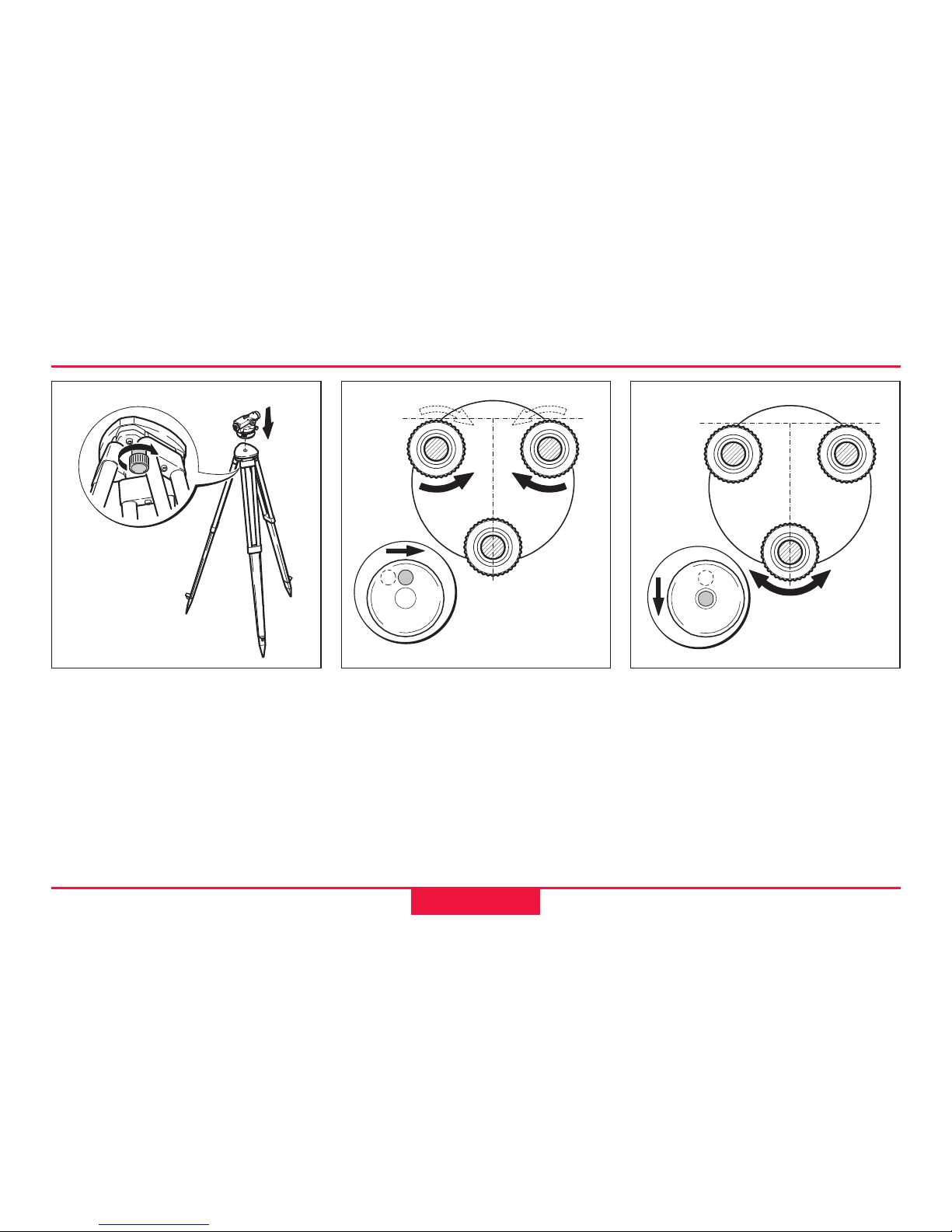
Levelling up
1. Place level onto tripod head.
Tighten central fixing screw of
tripod.
2. Turn footscrews of tribrach
into its centre position.
3. Centre circular level by
turning the foot screws.
Centring the circular level
1. Turn foot screws A and B
simultaneously in the opposite
direction until bubble is in the
centre (on the imaginary "T").
BL-12
BL-13
BL-14
BA
C
2. Turn foot screw C until bubble
is centred.
Page 13
Measurement preparation
13
RUNNER 20/24-1.0.1en
13
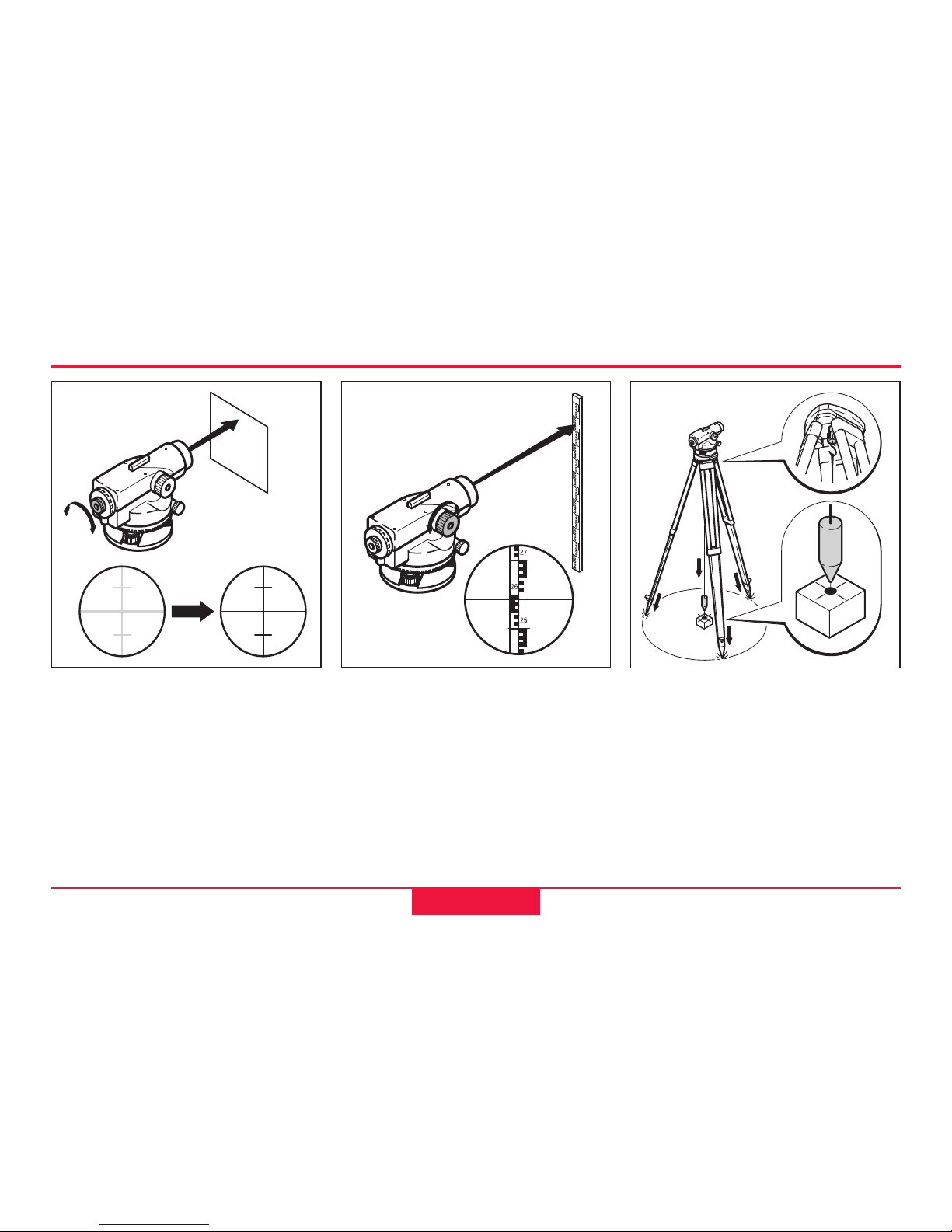
Focusing telescope
1. Aim telescope against a
bright background (e.g. white
paper).
2. Turn eyepiece until reticule is
sharp-focussed and deep
black. Now the eyepiece is
adapted to your eye.
3. Aim telescope on staff using
the optical sight.
4. Turn focussing knob until
image of staff is sharply
focussed. If the eye is moved
up and down behind the
eyepiece the image of the staff
and the reticule may not be
displaced against each other.
For possible centring over a
ground point:
1. Attach plumb bob.
2. Loosen central fixing screw
slightly and shift instrument
parallel on tripod until the
plummet is exactly over the
point.
3. Tighten central fixing screw.
Centring
BL-15
BL-16
BL-17
Page 14
14 Measuring
RUNNER 20/24-1.0.1en
Measuring
Before starting field work
or after longer periods of
storage/transport of your
equipment check the field
adjustment parameters
specified in this User Manual.
Reduce possible
vibrations by holding the
tripod legs.
If the optical parts of
your instrument are dirty
of fogged, your measurements
can be affected. Keep clean all
optical parts of your instrument
and follow the cleaning
instructions specified in the
User Manual.
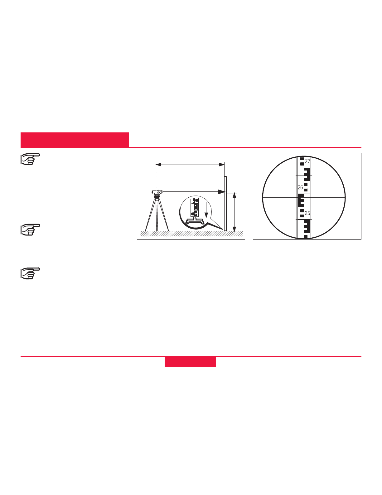
1. Setup instrument, level and
sharp-focus the reticule.
2. Setup level staff vertically
(refer also to Instruction
Manual of staff).
3. Roughly aim on staff using
the optical sight.
4. Sharp-focus using the
focussing knob.
Height reading
5. Fine-aim on staff using the
endless drives.
6. Check if circular level is
centred (view level prism).
7. Read off height H at the
centre hair of the reticule.
Example above:
H = 2.585 m
d
BL-25
BL-18
H
H
Page 15
Measuring
RUNNER 20/24-1.0.1en
15
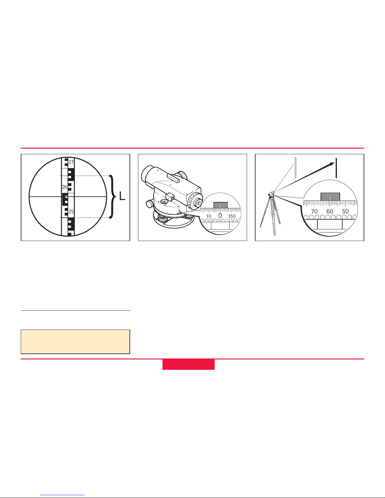
Result:
Distance d = 100 x L
Carry out steps 1 to 6 according
to height reading.
Reading:
Upper distance line: 2.670 m
Lower distance line: 2.502 m
Difference L: 0.168 m
Distance d: 16.8 m
Distance measuring
The instrument is equipped with
a horizontal circle. The
graduation is 1°.
Wanted:
Angle between point A and point
B.
Angle measuring
BL-23
BL-26
BL-27
A
B
Carry out steps 1 to 6 according
to height measuring. By doing
so, align the vertical hair of the
reticule to the staff centre.
7. Turn Hz-circle to "0".
8. Align instrument to point B
and aim on the centre of the
staff.
9. Read off Hz-angle from Hzcircle: Example above:
Hz = 60°.
Page 16
16 Measuring
RUNNER 20/24-1.0.1en
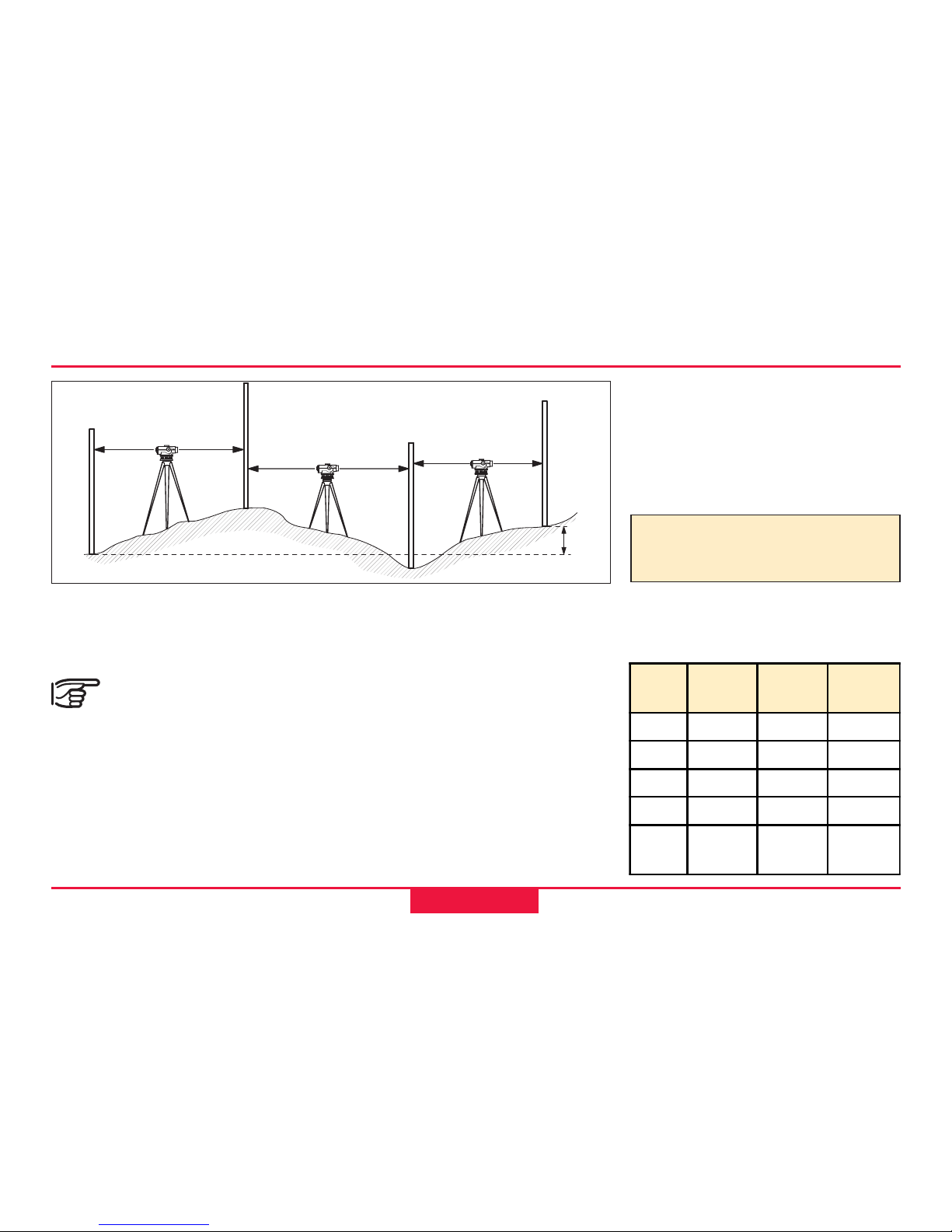
Wanted:
Height difference (∆H) between
point A and B.
Select instrument station
and staff location by
pacing off in that way, that
approximately the same target
distances are resulting (d1 ≈ d2;
approx. 40 to 50m).
Procedure:
1. Setup instrument at I1.
Line levelling
6. Carry out a foresight at
changepoint 3.
7. Continue in the same way
until height at point B is
measured.
Result:
∆∆
∆∆
∆H = sum backsight - sum
foresight
Point
No.
Back-
sight R
Fore-
sight V
Height
A
+2.502 650.100
2
+0.911 -1.803
3
+3.103 -1.930
B
-0.981 651.902
Sum
+6.516 -4.714
∆H=
+1.802
Example for the booking:
BL-28
A
B
2
3
RV
R
VR
V
I
2
I
3
d
1
d
2
∆H
I
1
2. Setup level staff vertically at
point A.
3. Aim on staff and read off and
take down height (backsight
R).
4. Setup level at the
changepoint 2, aim on staff
and read off and take down
height (foresight V).
5. Setup level at I2, airm on staff
at the hangepoint 2 and read
backsight and take down.
Page 17
Measuring
RUNNER 20/24-1.0.1en
17
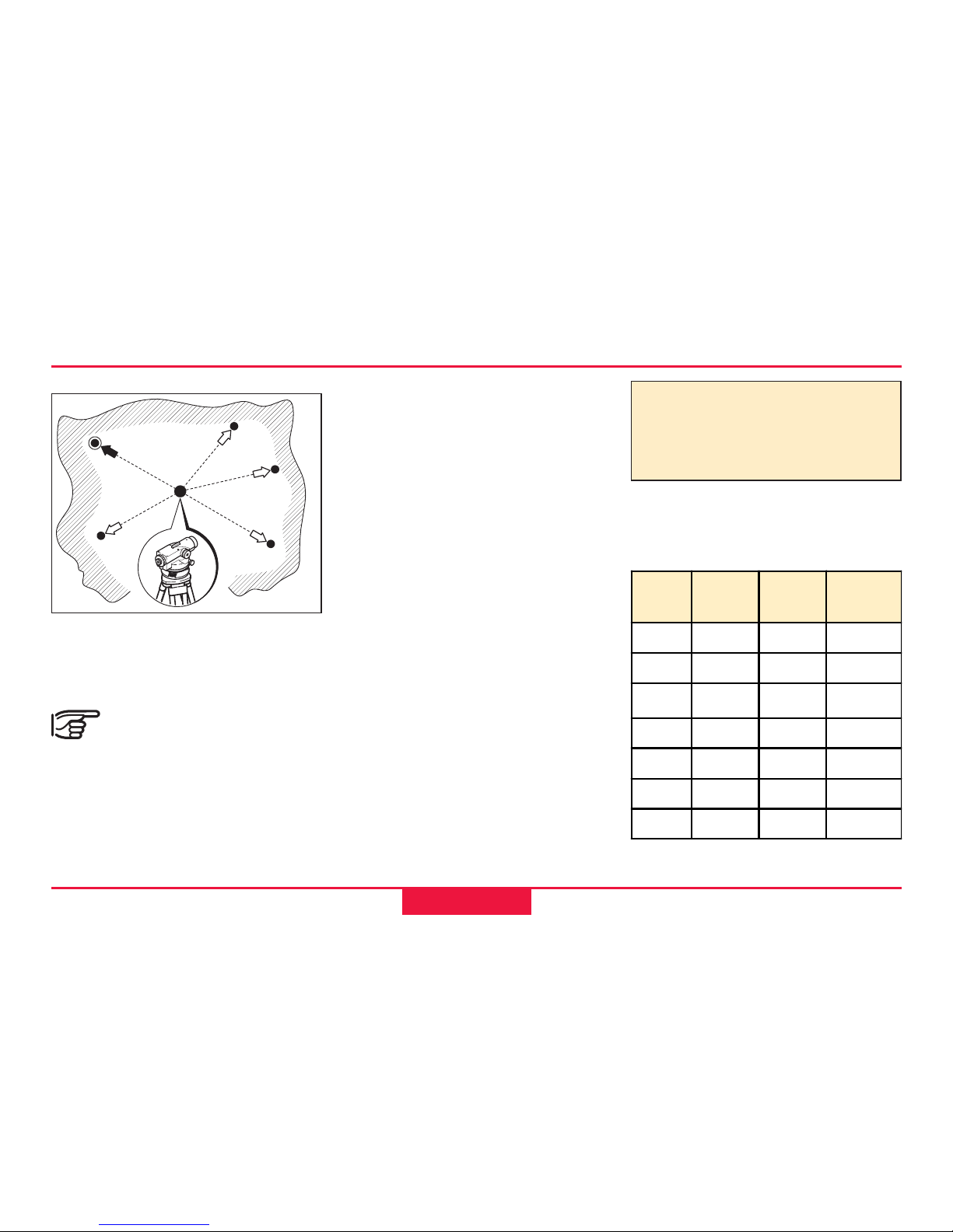
Wanted:
Height difference of several
reference points.
The required accuracy is
usually not very high
with such measurements.
Nevertheless, from time to time
read the staff on a stable
intermediate point (reading must
remain the same).
Area levelling
Procedure:
1. Set up instrument centrally
between the desired points.
The instrument telescope may
not be below the highest
measured intermediate point.
2. Set up staff vertically at
reference point A.
3. Aim on staff and read and
take down height (=backsight
to known point).
4. Set up staff vertically at
point 1.
5. Aim on staff and read and
take down height (=measuring
intermediate point,
intermediate sight)
6. Repeat steps 4 and 5 for
additional intermediate points.
7. The height of individual points
are:
BL-29
R
S1
A
1
2
3
4
S2
S3
S4
Height =
Height of station point
+ backsight (A)
- intermediate sight
Example for booking:
⊗ =Instrument horizon
Point
No.
Inte rm.
sight
Height
A 592.00
R1 +2.20
⊗
594.20
S1 -1.80 592.40
S2 -1.90 592.30
S3 -2.50 591.70
S4 -2.30 591.90
Page 18

18 Measuring
RUNNER 20/24-1.0.1en
Wanted:
Position of several ground
points.
The levelling total station
measuring is normally
carried out during area levelling.
Levelling total station measuring
Procedure:
1. Sequence of measurements
is the same as with area
levelling. However, beside the
height read also the staff
section L (see chapter
"Distance measuring") and
the Hz-angle.
2. Transfer measured value into
the map - points are determined by position and height.
Levelled stakeout
The stakeout is the counterpart
to the levelling total station
measuring - map points are set
out in the field.
Procedure:
1. Set up instrument at a known
point, centre and level up.
2. Focus instrument and aim on
known orientation point.
3. Orient horizontal circle (Hzdirection).
4. Move staff to stakeout point
due to known values
(distance and Hz-angle,
height) and stakeout point.
BL-36
BL-37
R
A
1
2
Backsight to known point Measuring ground points
A
Page 19
Checking and adjusting
RUNNER 20/24-1.0.1en
19
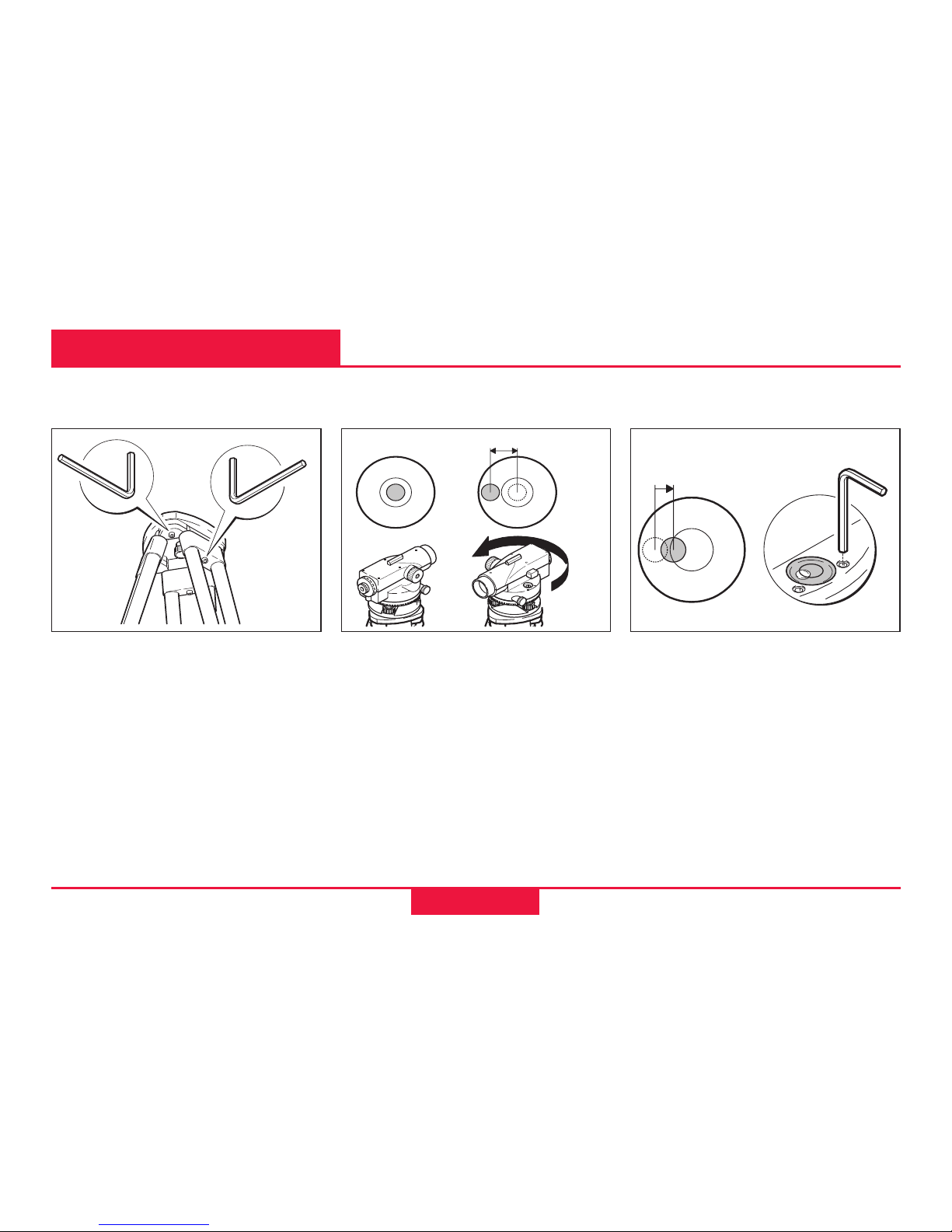
12
Checking and adjusting
1. Level up instrument.
2. Turn instrument by 180°.
3. If bubble of level is outside
the circle then it should be
adjusted (see point 4).
BL-31
Circular level
Connection of individual
elements must always be tight.
1.Tighten the Allen screws (2)
moderately (if available).
2. Tighten the articulated joints
on the tripod head (1) just
enough to keep the tripod
legs open when you lift it off
the ground.
Tripod
BL-30
4. Correct the half error using an
Allen key and repeat steps 2
and 3 until the bubble of level
is in the centre in any
telescope direction.
BL-32
∆
∆/2
1.
2.
3.
Page 20
20 Checking and adjusting
RUNNER 20/24-1.0.1en
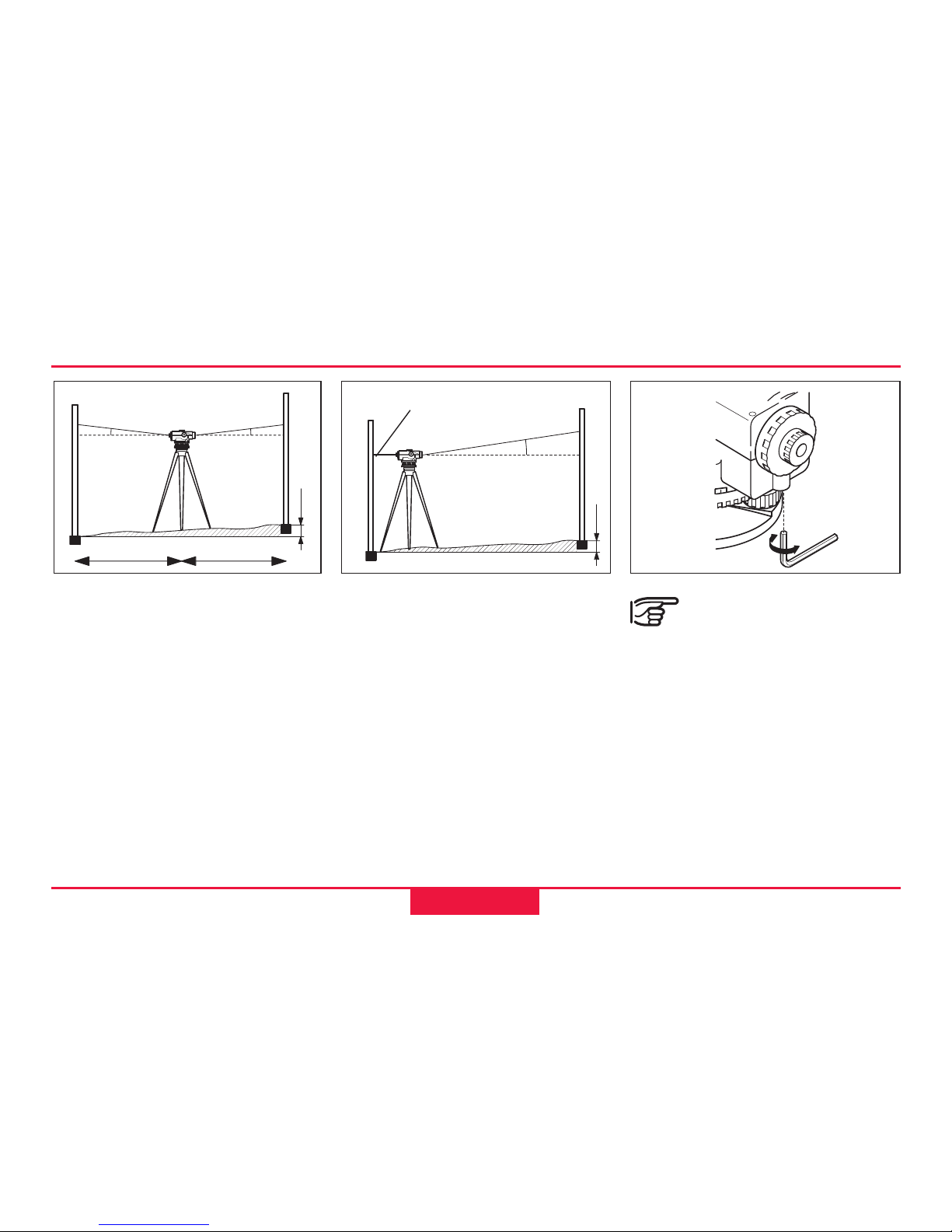
Checking and adjusting of the line-of-sight
With the circular bubble centred
and adjusted, the line of sight
should be horizontal.
Checking (see example):
1. Choose a distance of appr.
30 m within a gentle terrain.
2. Set up a staff at both final
points (A, B).
3. Set up the instrument at point
I1 (halfway between A and B,
just pass it down) and centre
the bubble.
4. Read both staffs.
reading on A = 1.832 m
reading on B = 1.616 m
∆H = A - B = 0.216 m
5. Set up the level about 1 m
from staff A
6. Read staff A (eg.: 1.604 m)
7. Find nominal reading B;
eg.: Reading A - ∆H =
1.604 m - 0.216 m = 1.388 m
8. Read staff B, compare
nominal-/actual- reading.
When the difference
nominal-/actual- reading
is more than 3 mm the line of
sight must be adjusted.
1. Turn the adjusting srew until
the midle hair gives the
required reading
(eg. 1.388 m).
2. Check line of sight again.
BL-33
BL-38
BL-34
I
1
B
A
H=1.832
H=1.616
B
A
actual=1.604
nominal
=1.388
I
2
d
d
∆H
∆H
δ
δ
δ
Page 21
Care and Storage
RUNNER 20/24-1.0.1en
21
When transporting or
shipping the equipment
always use the original packaging (transport case and shipping cardboard).
After a longer period of
storage or transport of
your instrument always check
the field ajustment parameters
indicated in this manual before
using the instrument.
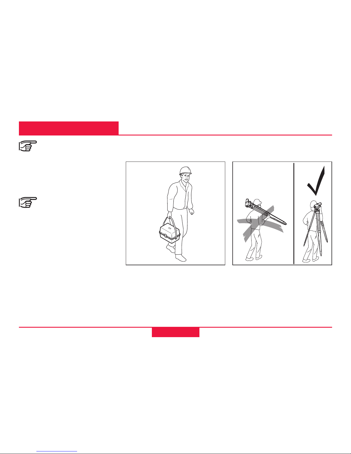
Care and Storage
In the field
When transporting the
equipment in the field, always
make sure to
• either carry the instrument in
its original transport case or,
• carry the tripod with its legs
splayed across your shoulder,
keeping the attached
instrument upright.
BL-19
BL-39
Transport
Page 22
22 Care and Storage
RUNNER 20/24-1.0.1en
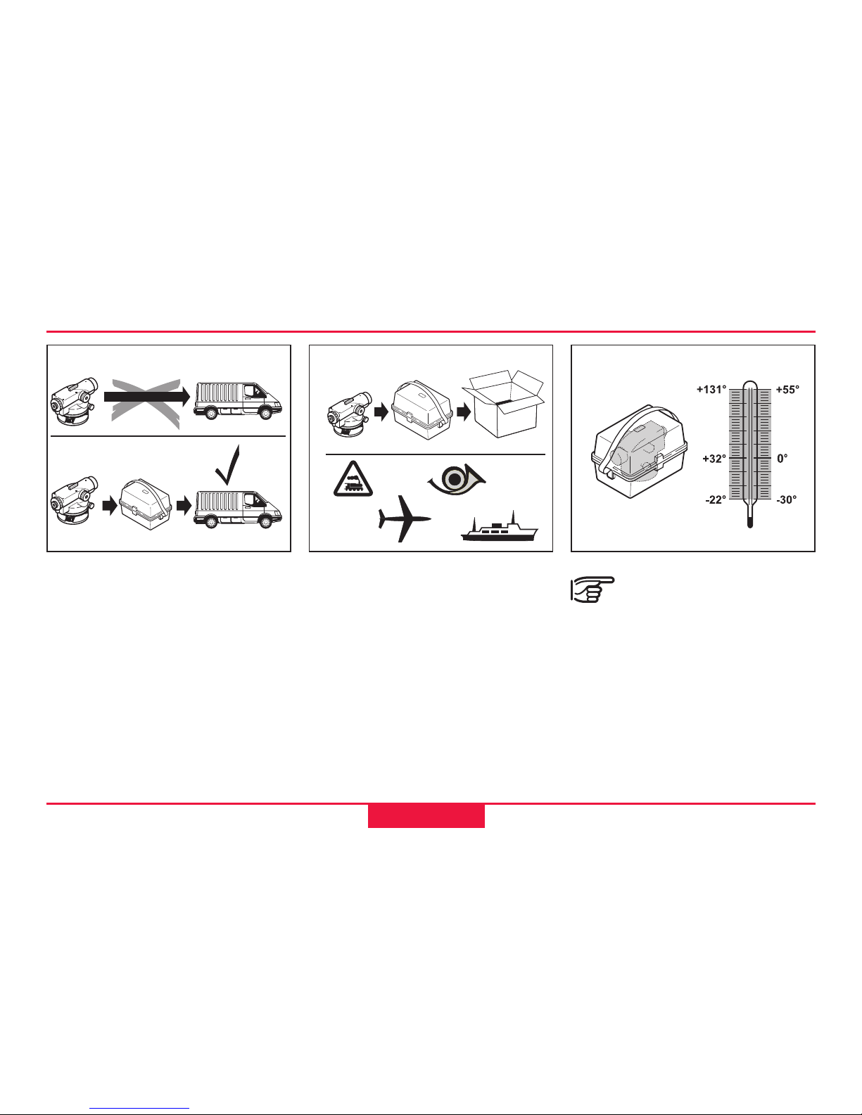
Never transport the instrument
loose inside the vehicle.
The instrument can be damaged
by blows and vibrations.
It must always be transported in
it's case and be properly
secured.
Storage
When storing the
equipment, particularly in
summer and inside a vehicle,
take the temperature limits into
account. (-30°C to +55°C /
-22°F to +131°F).
Inside vehicle Shipping
For shipping the instrument by
rail, aircraft or ship use the
original packaging (transport
case or shipping cardboard) or
another suitable packaging
securing the instrument against
blows and vibrations.
BL-22
BL-21
BL-20
°F C°
Page 23
Care and Storage
RUNNER 20/24-1.0.1en
23
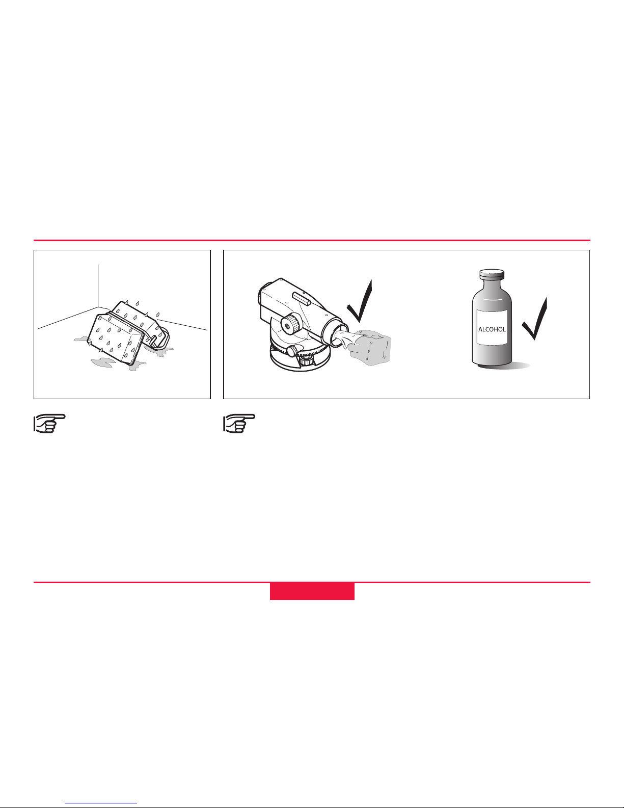
Cleaning
Objective, eyepiece:
• Blow dust off lenses and
prisms
• Never touch the glass with
fingers
• Use only a clean, soft and
lint-free cloth for cleaning. If
necessary, moisten the cloth
with pure alcohol.
Storage, continued
If the instrument becomes wet, leave it un-
packed. Wipe down, clean, and
dry the instrument (at not more
than 40 °C/ 104°F), transport
case, foam inserts, and accessories. Pack up the equipment
only when it is perfectly dry.
When using the instrument in
the field always close the
transport case.
Use no other liquids; these may
attack polymer components.
BL-40
BL-24
Page 24

24 Safety Directions
RUNNER 20/24-1.0.1en
Safety Directions
The following directions should
enable the person responsible
and the person who actually
uses the instrument, to
anticipate and avoid operational
hazards.
The person responsible for the
instrument must ensure that all
users understand these
directions and adhere to them.
Permitted uses
The automatic level is intended
to the following applications:
• Construction surveying
• Line and area levellings
• Height readings
• Optical distance measuring
with stadia readings
• Angle measurements and
staking out with horizontal
circle
Intended use of instrument
Adverse uses
• Use of the level without
previous instruction
• Use outside of the intended
limits
• Disabling safety systems and
removal of hazard notices
• Opening the instrument using
tools (screwdriver, etc.),
unless this is specifically
permitted for certain functions
• Modification or conversion of
the instrument
• Use after misappropriation
Page 25
Safety Directions
RUNNER 20/24-1.0.1en
25
• Use with accessories from
other manufacturers without
the prior express approval of
Leica Geosystems GR LLC
• Aiming directly into the sun
• Inadequate safeguards at the
surreying site (e.g. when
measuring on roads, etc.)
Limits of use
Environment:
Suitable for use in an
atmosphere appropriate for
permanent human habitation:
not suitable for use in aggressive or explosive environments.
Use in rain is permissible for
limited periods (splash-water
proof).
Refer to section
"Technical Data".
Adverse uses, contd.
WARNING:
Adverse use can lead to
injury, malfunction, and material
damage.
It is the task of the person
responsible for the instrument to
inform the user about hazards
and how to counteract them.
The equipment may only be
used if the user is properly
instructed.
Page 26
26 Safety Directions
RUNNER 20/24-1.0.1en
Responsibilities
Area of responsibility for the
manufacturer of the original
equipment Leica Geosystems
GR LLC , Grand Rapids,
MI 49546, USA:
(hereinafter referred to as
Leica Geosystems GR LLC)
Leica Geosystems GR LLC is
responsible for supplying the
product, including the user
manual and original
accessories, in a completely
safe condition.
Responsibilities of the
manufacturers of non-Leica
Geosystems GR LLC
accessories:
The manufacturers of
non-Leica Geosystems
accessories are responsible for
developing, implementing and
communicating safety concepts
for their products, and are also
responsible for the effectiveness
of those safety concepts in
combination with the Leica
Geosystems GR LLC product.
Responsibilities of the person
in charge of the instrument:
WARNING:
The person responsible
for the instrument must
ensure that it is used in accordance with the instructions. This
person is also accountable for the
training and deployment of
personnel who use the instrument
and for the safety of the
equipment when in use. The
person in charge of the instrument
has the following duties:
• To understand the safety
instructions on the product and
the instructions in the User
Manual.
• To be familiar with local regu-
lations relating to accident
prevention.
• To inform Leica Geosystems GR
LLC immediately if the
equipment becomes unsafe.
Page 27
Safety Directions
RUNNER 20/24-1.0.1en
27
Hazards of use
WARNING:
The absence of
instruction, or the inadequate
imparting of instruction, can
lead to incorrect or adverse use,
and can give rise to accidents
with far-reaching human,
material, financial and environmental consequences.
Precautions:
All users must follow the safety
directions given by the
manufacturer and the directions
of the person responsible for the
instrument.
CAUTION:
Watch out for erroneous
measurements if the instrument
is defective or if it has been
dropped or has been misused or
modified.
Precautions:
Periodically carry out test
measurements and perform the
field adjustments indicated in
the User Manual particularly
after the instrument has been
subjected to abnormal use and
before and after important
measurements.
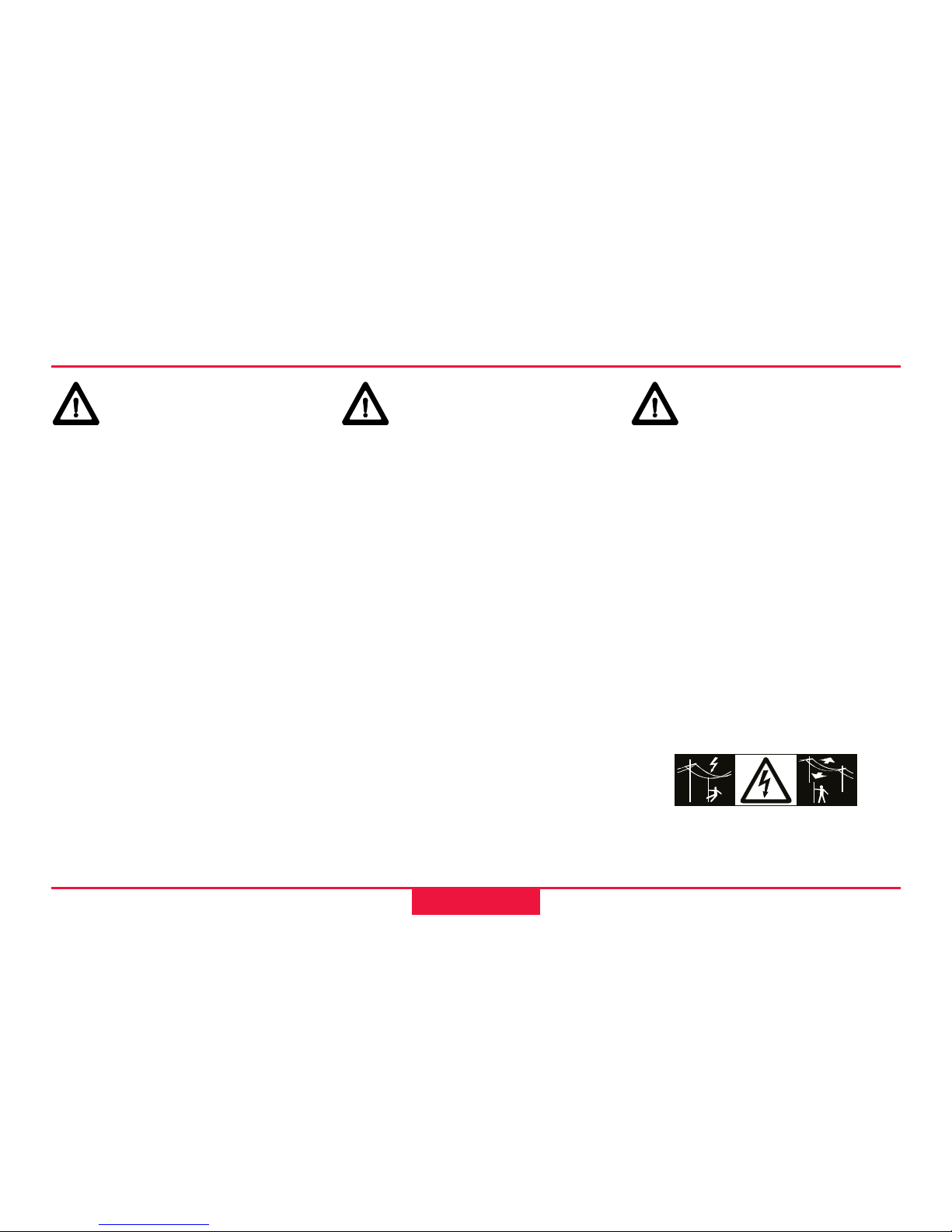
DANGER:
Because of the risk of
electrocution, it is very
dangerous to use levelling staffs
and extensions in the vicinity of
electrical installations such as
power cables or electrical
railways.
Precautions:
Keep at a safe distance from
electrical installations. If it is
essential to work in this
environment, first contact the
safety authorities responsible for
the electrical installations and
follow their instructions.
Page 28
28 Safety Directions
RUNNER 20/24-1.0.1en
WARNING:
By surveying during a
thunderstorm you are at risk
from lightening.
Precautions:
Do not carry out field surveys
during thunderstorms.
Hazards of use, continued
WARNING:
Inadequate securing of
the surveying site can lead to
dangerous situations, for
example in traffic, on building
sites and at industrial
installations.
Precautions:
Always ensure that the
surreying site is adequately
secured. Adhere to the local
regulations governing accident
prevention and road traffic.
CAUTION:
Be careful when aiming
your level into the sun. Direct
sun radiation can hurt your
eyes.
Precautions:
Do not aim directly to the sun.
Page 29
Safety Directions
RUNNER 20/24-1.0.1en
29
CAUTION:
If the accessories used
with the instrument are not
properly secured, and the
equipment is subjected to
mechanical shock (e.g. blows,
falling etc.), the equipment may
be damaged safety devices may
be ineffective or people may
sustain injury.
Hazards of use, continued
Precautions:
When setting-up the instrument,
make sure that the accessories
(e.g. tripod, staff, staff brace, ...)
are correctly adapted, fitted,
secured and locked in position.
Avoid subjecting the equipment
to mechanical shock.
Never position the instrument on
the tripod baseplate without
securely tightening the central
fixing screw. If the screw is
loosened always remove the
instrument immediately from the
tripod.
CAUTION:
When using a vertical
staff supported by one brace
there is always the danger of
falling (e.g. by wind gusts) and
therefore danger of damage to
equipment and danger of
personal injuries.
Precautions:
Never leave a vertical staff
supported by a brace
unsupervised (person at the
staff).
Page 30

30 Safety Directions
RUNNER 20/24-1.0.1en
WARNING:
If the equipment is
improperly disposed of, the
following can happen:
• If polymer parts are burnt,
poisonous gases are
produced which may impair
health.
• By disposing of the equipment
irresponsibly you may enable
unauthorized persons to use it
in contravention of the
regulations, exposing
themselves and third parties
to the risk of severe injury and
rendering the environment
liable to contamination.
Hazards of use, continued
Precautions:
Dispose of the equipment
appropriately in accordance with
the regulations in force in your
country. Always prevent access
to the equipment by
unauthorized personnel.
Page 31
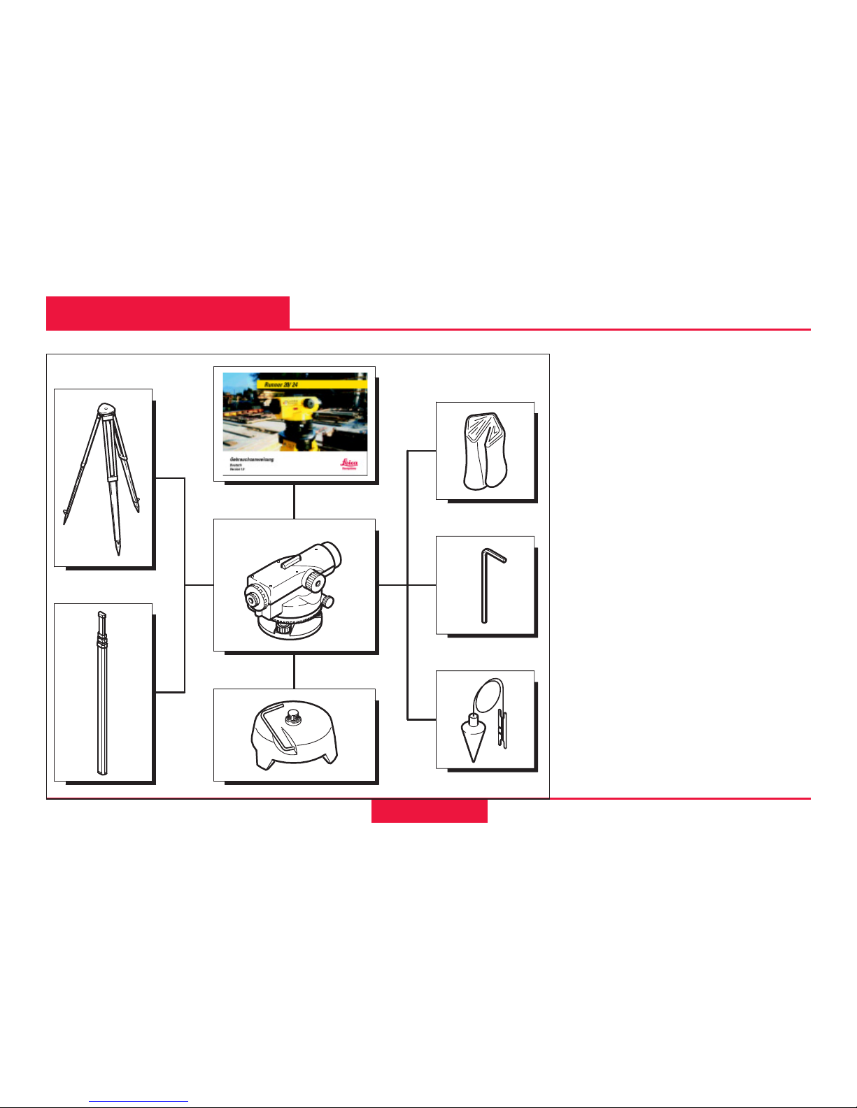
RUNNER 20/24-1.0.1en
31
Accessories
User Manual
Protective cover
Allen key
Plumb bob (option)
Level base (option)
Standard level staff (option)
Tripod (option)
BL-41
Accessories
Page 32

RUNNER 20/24-1.0.1en
32
Technical Data
Accuracy:
• Standard deviation for 1 km
double levelling
RUNNER 20 2,5 mm
RUNNER 24 2,0 mm
Telescope:
•Erect image
• Magnification
RUNNER 20 20 x
RUNNER 24 24 x
• Field of view at 100 m > 2.3 m
• Shortest target distance
from instrument axis 0,8 m
Distance measurement:
• Multiplication factor 100
• Additive constant 0
Compensator:
• Working range ± 15'
• Setting accuracy
(standard deviation) 0,5"
Circular level:
• Sensitivity 10' / 2 mm
Cirkel:
• Graduation 360°
• Graduation interval 1°
Adaption:
• To normal or ball head tripod
Temperature range:
• Storage - 30°C bis + 55°C
(-22°F bis +131°F)
• Operating - 20°C bis + 50°C
(-4°F bis +122°F)
Technical Data
Page 33

RUNNER 20/24-1.0.1en
33
Index
Index
A
Accident prevention ..................................... 28
B
Booking ................................................. 16, 17
Bubble ................................................... 12, 19
C
Central fixing screw ..................................... 12
Centring ........................................................ 13
Circular level ......................................... 12, 14
Compensator ................................................. 9
D
Distance line ................................................ 15
E
Electrical installations .................................. 27
Environment ................................................. 25
Eyepiece ...................................................... 13
H
Height difference ............................. 9, 16, 17
Horizontal circle ........................................... 15
Hz-angle ....................................................... 18
Hz-circle ....................................................... 15
O
Optical sight .......................................... 13, 14
P
Packaging .................................................... 22
Plummet ....................................................... 13
Protective cover ........................................... 20
R
Rearrangement point ................................... 16
Reticule ................................................. 13, 14
Page 34

RUNNER 20/24-1.0.1en
34
Index, continued
Index
S
Safe distance ............................................... 27
Sharp-focus ................................................. 14
Shipping ................................................ 21, 22
Storage ......................................................... 21
Storing .......................................................... 22
T
Target distances .......................................... 16
Transport case ...................................... 21, 23
V
Vibrations ..................................................... 14
W
Wet instrument ............................................ 23
Page 35

RUNNER 20/24-1.0.1en
35
Page 36

Printed in Switzerland Copyright Leica Geosystems GR LLC,
729541-1.0.1en
Leica Geosystems GR LLC
is an ISO 9001
Registered Company
Survey Instrument Sales
24037 Acacia
Redford, MI 48239
www.surveyinstrumentsales.com
 Loading...