

Page 1

Version 1.0
English
GeoAce RTK Base
Station
User Manual
Page 2
GeoAce, Introduction
Introduction
Purchase Congratulations on the purchase of a Leica GeoAce RTK Base Station.
This manual contains important safety directions as well as instructions for setting
up the product and operating it. Refer to "6 Safety Directions" for further information.
Read carefully through the User Manual before you switch on the product.
2
Product
identification
The type and serial number of your product are indicated on the type plate.
Enter the type and serial number in your manual and always refer to this information
when you need to contact your agency or Leica Geosystems authorised service workshop.
Type: _______________
Serial No.: _______________
Page 3
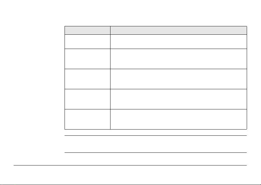
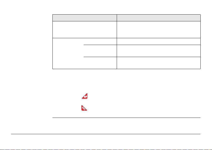
Symbols The symbols used in this manual have the following meanings:
Type Description
DANGER Indicates an imminently hazardous situation which, if not
WARNING Indicates a potentially hazardous situation or an unintended
CAUTION Indicates a potentially hazardous situation or an unintended
NOTICE Indicates a potentially hazardous situation or an unintended
avoided, will result in death or serious injury.
use which, if not avoided, could result in death or serious
injury.
use which, if not avoided, may result in minor or moderate
injury.
use which, if not avoided, may result in appreciable material,
financial and environmental damage.
Important paragraphs which must be adhered to in practice as
they enable the product to be used in a technically correct and
efficient manner.
Validity of this
manual
GeoAce, Introduction 3
This manual applies to the GeoAce RTK Base Station.
Page 4
GeoAce, Introduction
Available documentation
4
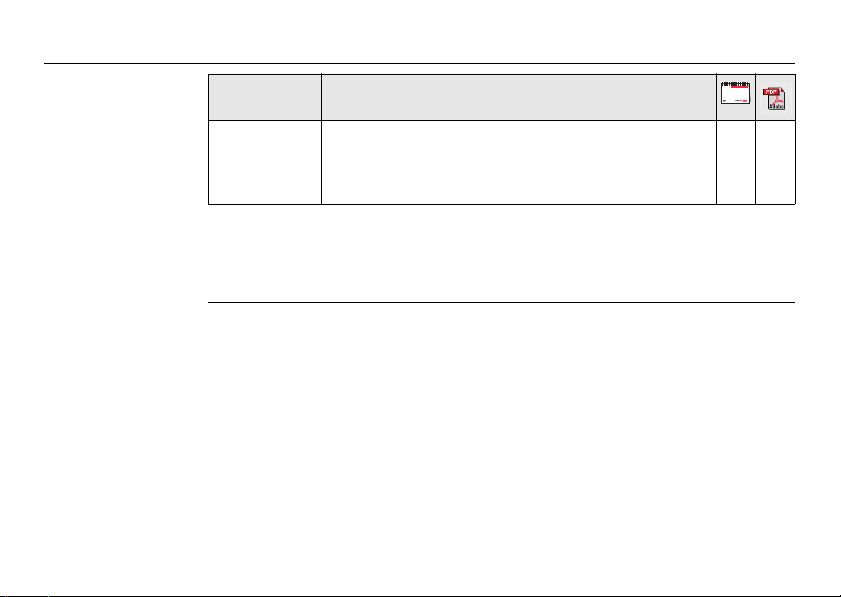
Name Description/Format
Leica GeoAce
RTK Base
Station User
Manual
Refer to the following resources for all Leica GeoAce RTK Base Station documentation/software:
• www.agguidance.com
• www.virtualwrench.com
All instructions required in order to operate the product
to a basic level are contained in the User Manual.
Provides an overview of the product together with technical data and safety directions.
Page 5

Table of Contents
In this manual Chapter Page
1 Unpacking the Instrument
1.1 Leica GeoAce RTK Base Station Container Contents 8
1.2 Additional Packaging Content 11
2 Leica GeoAce RTK Base Station User Interface
2.1 Main Screen 17
2.2 Main Menu 21
2.3 Channel 22
2.4 Settings 24
2.4.1 Position Mode 26
2.4.2 Data Format 31
2.4.3 Internal Radio 32
2.4.4 GLONASS 36
2.4.5 Region 37
2.4.6 Language 38
2.4.7 Network 39
2.4.8 Saved Positions 41
2.4.9 Serial Port 42
GeoAce, Table of Contents 5
12
8
Page 6

GeoAce, Table of Contents
3 Using the Leica GeoAce RTK Base Station
4 Setup
6
2.4.10 Cell Modem Settings 44
2.4.11 Backup Configuration 45
2.4.12 Load Config from USB 47
2.5 Service 49
2.5.1 Status 50
2.5.2 System Info 52
2.5.3 Software Update 54
2.5.4 Logging 57
2.5.5 Rollback Software 58
2.5.6 Reset Defaults 59
2.5.7 Reset GPS 61
2.5.8 Virtual Wrench 62
2.5.9 Extended Features 64
66
3.1 Mounting on Tripod 66
3.2 Installing the Internal Battery 68
3.2.1 General Battery Handling 70
3.3 Installing a SIM Card 71
73
4.1 Real-Time Base Setup 73
Page 7

5 Care and Transport
5.1 Transport 75
5.2 Storage 76
5.3 Cleaning and Drying 77
6 Safety Directions
6.1 General Introduction 78
6.2 Definition of Use 79
6.3 Limits of Use 81
6.4 Responsibilities 82
6.5 Hazards of Use 84
6.6 Electromagnetic Compatibility EMC 93
6.7 FCC Statement, Applicable in U.S. 96
7 Technical Data
7.1 Technical Data 99
7.1.1 Tracking Characteristics 104
7.2 Conformity Declarations 106
8 Software Licence Agreement
Index
GeoAce, Table of Contents 7
75
78
99
108
110
Page 8

GeoAce, Unpacking the Instrument
1 Unpacking the Instrument
1.1 Leica GeoAce RTK Base Station Container Contents
Description The container configuration covers most GNSS reference setup cases.
8
Page 9
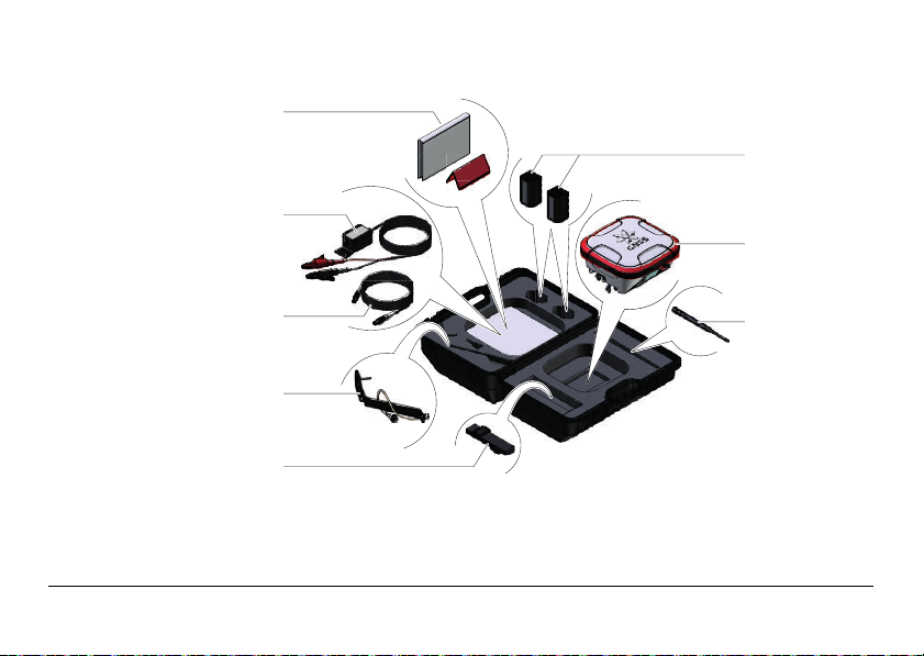
Container Leica
GeoAce
Container configuration for Leica GeoAce RTK Base Station.
a
f
b
g
c
d
e
004176_001
h
GeoAce, Unpacking the Instrument 9
Page 10

GeoAce, Unpacking the Instrument
a) User Manual (printed), Multilingual
auxiliary Safety Guide
b) GEV71, 12V Car Battery adapter
c) GEV219, 1.8m Power Cable
d) Antenna bracket and cable
assembly
10
e) Hand strap
f) 7.4V/6000mAh (x2), Li-Ion Batteries
type GEB222
g) GeoAce RTK Base Station with internal
radio (if applicable)
h) Whip antenna
Page 11
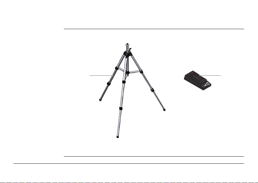
1.2 Additional Packaging Content
Additional
Items in additional packaging:
Packaging
ab
004177_001
a) Light Duty Tripot
b) GKL211,Battery charger
GeoAce, Unpacking the Instrument 11
Page 12
GeoAce, Leica GeoAce RTK Base Station User Interface
004183_001
a
b
c
d
e
f
g
h
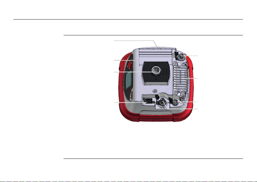
2 Leica GeoAce RTK Base Station User Interface
Ports and
connections
12
a) Battery cover
b) Internal cell phone antenna
c) Tripod mounting point
d) USB A data port
e) External GPS antenna connector (TNC)
f) Internal radio module
g) External power and radio cable
connector
h) Radio whip antenna snap on
connector
Page 13
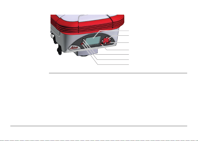
User Interface
overview
a
b
a) Display
c
b) Navigation keys
c) ENTER key
d
d) ESC key
e
e) Ambient light sensor
f
f) Power and status LED
004178_001
GeoAce, Leica GeoAce RTK Base Station User Interface 13
g
g) ON/OFF key
Page 14
GeoAce, Leica GeoAce RTK Base Station User Interface
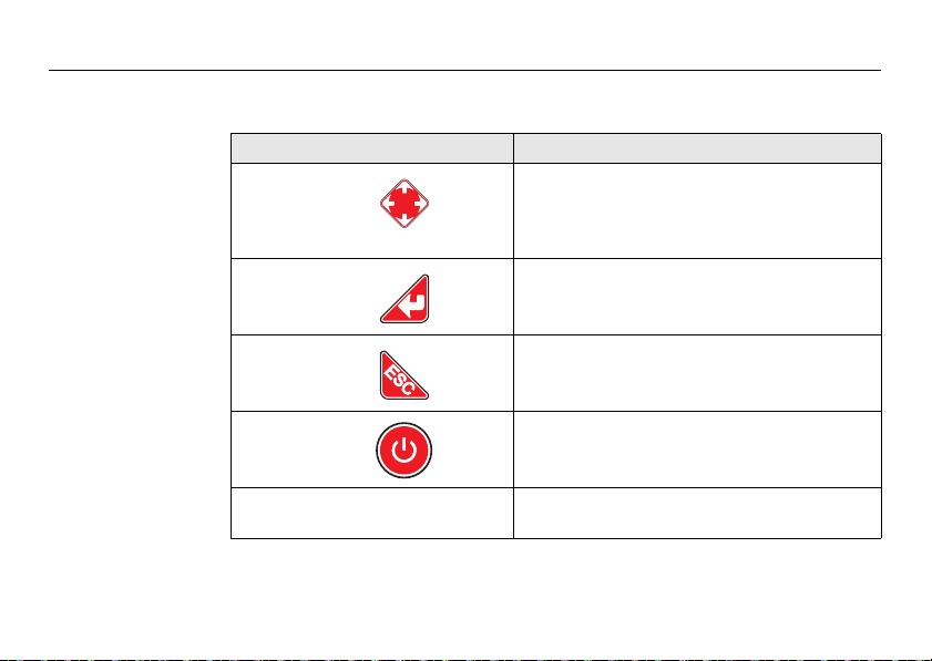
User Interface
elements
The instrument is used as a stand-alone or network RTK Base Station. It is controlled
via the user interface buttons.
Element Function
Navigation keys • 4-way navigation in the menus via left,
Enter • To activate editing.
ESC • To cancel operations.
right, up and down key.
The right navigation key can also be
used to enter a menu or submenu
• To accept changes.
• To enter a menu or submenu.
• To leave a menu.
14
ON/OFF key • Allows access to startup (press for two
Graphical
display
seconds) and shutdown.
• Displays status informations and software
functions.
Page 15
Element Function
Ambient light
sensor
Power LED off • Instrument is switched off.
continuously red • Instrument is booting.
continuously
green
Use the navigation keys to select a program icon and to navigate within
submenus.
Use the key to enter a submenu and confirm settings.
Use the key to discard settings, cancel operations and to go back to the
main menu or main status screen.
GeoAce, Leica GeoAce RTK Base Station User Interface 15
• For future power saving implementation.
Currently, background light turns off
after 1 minute of no activity.
• Position not acquired.
• Normal operation mode.
• Position acquired
Page 16

GeoAce, Leica GeoAce RTK Base Station User Interface
First time use /
Reset Defaults
When the Base Station is turned on for the very first time or after a Reset Defaults
has been performed the display will show the following two menu items in order.
• Language - refer to section " Language - Menu Content" to set the language.
• Region - refer to section " Region - Menu Content" to set the region.
Fully charge the battery with the external charger before turning on the Base
Station for the first time.
16
Page 17
2.1 Main Screen
004185_001
About the Main
The Main Screen is the first screen that is displayed after boot-up.
Screen
Main Screen
Content
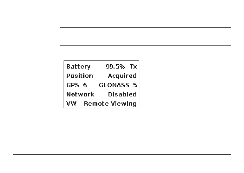
The Main Screen shows the status of the main components of the Base Station:
1) External Power or Battery with
power indicator / Transmit and
Logging Status
2) Position Status
3) Number of tracked satellites for
GPS and GLONASS
4) Network Status
5) Virtual Wrench Status
External Power and
The display content varies according to the system status:
Battery Power
• External Power - The instrument is connected to an external power source.
• Battery - The instrument uses internal battery power. The power level is indicated in per cent.
GeoAce, Leica GeoAce RTK Base Station User Interface 17
Page 18

GeoAce, Leica GeoAce RTK Base Station User Interface
The internal battery does not get charged when external power is being
used. The battery can only be charged in the external charger which is
provided in the box.
18
Transmitting and
Logging Status
Position Status The display content varies according to the system status:
The display content varies according to the system status:
• TX flashes:
– once a second to show transmitting data is in progress if an internal radio is
selected.
– every 15 seconds when instrument is waiting on position data.
• Lg - The instrument is logging data to a USB Flash Drive.
TX / Lg will be flashed alternatively if transmitting and logging is active.
• Waiting - The instrument is in the process of acquiring a position.
• Time remaining (Average Position mode active) - Countdown to complete the
position average. This requires an adequate set of satellites.
• Acquired - The instrument has a position fix.
Page 19

Tracking Status The display content varies according to the system status:
• GPS - The number of tracked satellites is displayed.
• GLONASS - If activated, the number of tracked satellites is displayed.
Network Status The display content varies according to the system status:
• Spider OK - The instrument is connected to the network.
• Spider Not OK - The instrument is not connected to the network. Either no
internet connection is available or network settings are incorrect.
• Network Disabled - Either the network extended feature is locked or the
network is disabled.
If the network option is not available under Settings Menu, an unlock code is
required to unlock this feature.
GeoAce, Leica GeoAce RTK Base Station User Interface 19
Page 20

GeoAce, Leica GeoAce RTK Base Station User Interface
Virtual Wrench
Status
The display content varies according to the system status:
• Not Connected - The instrument is not connected to Virtual Wrench.
• Connecting - The instrument is connecting to Virtual Wrench.
• Connected - The instrument is connected to Virtual Wrench.
• Remote Viewing - The instrument is being viewed remotely by Virtual Wrench.
20
Page 21
2.2 Main Menu
004186_001
About the Main
Menu
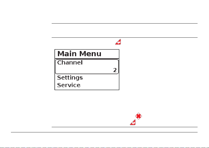
Main Menu Content To enter the Main Menu, press the button from the Main Screen.
GeoAce, Leica GeoAce RTK Base Station User Interface 21
The Main Menu is used to setup the instrument.
1) Channel - Change the radio
channel or turn the internal radio
off. The active radio channel is
displayed.
2) Settings - To enter the Settings
Menu
3) Service - To enter the Service
Menu
If the internal radio type does not comply to the regional radio regulations:
The message Invalid Radio is displayed under Channel. This is an inten-
tional limitation and enforced in the software.
To select any of these options, use the up/down keys to scroll to the
required menu option and press the key to enter that menu option.
Page 22

GeoAce, Leica GeoAce RTK Base Station User Interface
004187_001
2.3 Channel
22
About the Channel
Menu
Channel Menu
Content
The Channel Menu is used to change the channel of the internal radio.
If no internal radio is installed no settings can be done here and OFF is
displayed.
From the Main Menu screen select Channel. Press the button to enter the
menu.
• Off will be displayed if no radio is
installed or radio is disabled.
• 0 - 19 - a 900 MHz radio is installed
(North America / Australia)
• 0 - 4 - a 868 MHz radio is installed
(Europe)
Channel settings can also be done under Settings > Internal Radio >
Channel. See also "Internal Radio - Menu Content".
Page 23
How to Select a
Radio Channel
GeoAce, Leica GeoAce RTK Base Station User Interface 23
Use the up/down keys to select a Channel. Press the button to save the
changes.
All RTK devices must use the same channel settings communicate with each
other (e.g. to send and receive correction data).
To save battery power, switch off the internal radio if it is not used (e.g.
when an external radio is in use).
Page 24
GeoAce, Leica GeoAce RTK Base Station User Interface
004188_001
2.4 Settings
24
About the Settings
Menu Screen
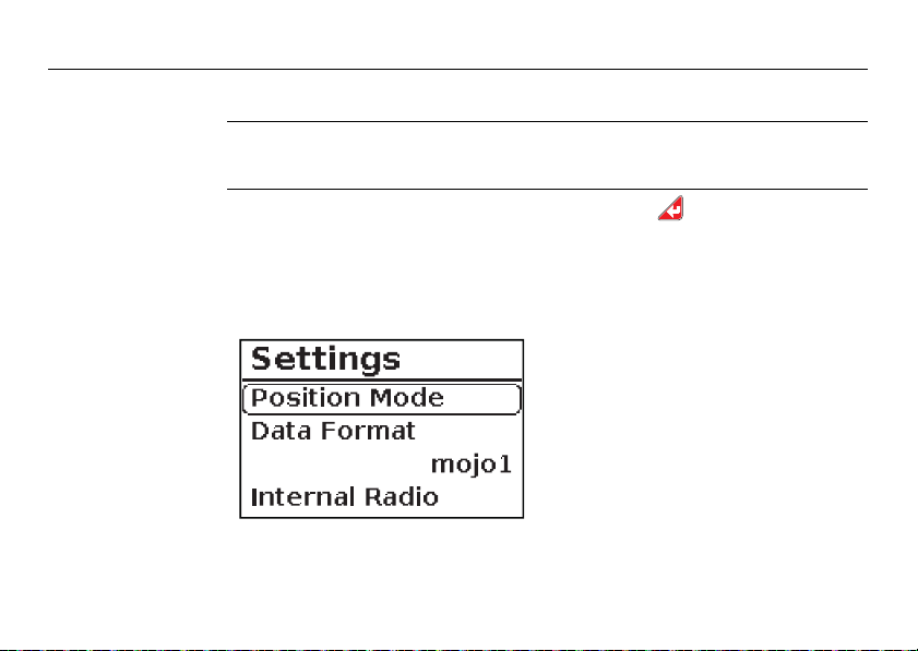
Settings Menu
Content
The Settings menu is used to change how the instrument operates.
From the Main Menu screen select Settings. Press the button to enter the
menu.
These Settings Menu options are explained further in the following
sections.
Available settings:
• Position Mode
• Data Format
• Internal Radio
• GLONASS
• Region
• Language
•(Network) - Only visible if feature
is unlocked.
Page 25
• Saved Positions
• Serial Port
• Cell Modem Settings
• Backup Configuration
• Load Config from USB
To select any of these options, use the up/down keys to scroll to the
required menu option and press the key to enter that menu option.
GeoAce, Leica GeoAce RTK Base Station User Interface 25
Page 26
GeoAce, Leica GeoAce RTK Base Station User Interface
004189_001
2.4.1 Position Mode
26
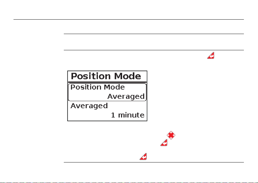
About the Position
Mode
Position Mode
Menu Content
The Position Mode menu is used to change the type of Position Mode the instru-
ment will use.
From the Settings Menu screen select Position Mode. Press the button to
enter the menu.
Available settings:
• Snap Previous
• Averaged
• Fixed Position
To select any of these options, use the up/down keys to scroll to the
required menu option and press the key to enter that menu option.
To save changes press the key.
Page 27

Snap Previous Snaps a previously used position and reports it again. This is done for in-field repeat-
ability with ease of setup.
The Instrument must be re-positioned at the exact same position to deter-
mine that this particular location has been used before.
Averaged position information are automatically used for faster re-localisa-
tion when switching from Averaged to Snap Previous mode.
When changing from Fixed Position to Snap Previous mode, it takes
approximately 1 minute to snap a position or create a new one.
Averaged The instrument will average its position for a preset amount of time. This averaging
GeoAce, Leica GeoAce RTK Base Station User Interface 27
results in a new position. It is done every time the base station starts up.
• 1 minute (default setting)
• 5 minutes
• 15 minutes
• 30 minutes
• 1 hour
• 6 hours
• 12 hours
• 24 hours
Long time averaging can be used e.g. for position data acquisition for Fixed
Position mode.
Page 28

GeoAce, Leica GeoAce RTK Base Station User Interface
Influence of
Average Time
Settings
Changing the Averaged time settings has influence on the accuracy of the absolute
position values.
Changing the averaging time is possible at any time. Changing these time
settings has an effect on the position value and can result in an offset to
the previously used position.
Averaging calculation is done continuously in the background, independent
of the chosen time settings. This allows switching between different settings
without position reporting delay - taking the already lapsed measurement
time period into account.
Effects when increasing the averaging time:
• The absolute position may be more accurate.
• A more accurate absolute positions will not affect the relative accuracy (e.g.
accuracy of ploughing lines)
Effects when decreasing the averaging time:
• The absolute position may be less accurate.
• A less accurate absolute position will not affect the relative accuracy (e.g. accuracy of ploughing lines)
28
Page 29
Fixed Position Manually set the instrument to report a fixed position or automatically take over posi-
GeoAce, Leica GeoAce RTK Base Station User Interface 29
tion data from other operating modes (e.g. Snap Previous and Averaged). This
position will be used unless the position mode or the Fixed Position is changed.
When position data are available simply switch to Fixed Position mode. The
position values will be taken over. No further set up is required.
At an unknown position the long time Averaged (e.g. 12 or 24h) function-
ality can be used to acquire accurate position data. When the averaging is
done and position data are available, simply switch to Fixed Position mode.
Input formats:
• Latitude and longitude - in degrees / minutes / seconds or decimal degrees
• Height - in meters or feet
How to set position values manually:
1) To enter a fixed position select Latitude, Longitude or Height and press
. Use the navigation keys to move the cursor and to change the
settings to the required value.
Page 30
GeoAce, Leica GeoAce RTK Base Station User Interface
2) Use the navigation keys to move the cursor and to change the settings to
the required value.
3) To save changes press the key.
When the input mode is toggled between decimal degrees and deg/min/sec
the unit of all displayed values will toggle accordingly.
It is recommended to keep a record of the fixed position as a backup.
30
Page 31

2.4.2 Data Format
004194_001
About the Data
Format
Data Format Menu Content
GeoAce, Leica GeoAce RTK Base Station User Interface 31
The Data Format option is used to change the output format of the correction data
which are distributed by the instrument.
From the Settings Menu screen select Data Format. Press the button to enter
the menu.
Available data formats:
1) RTCM3.0
2) CMR
3) mojo1
To select any of these options, use the up/down keys to scroll to the
required menu option and press the key to enter that menu option.
Page 32

GeoAce, Leica GeoAce RTK Base Station User Interface
004195_001
2.4.3 Internal Radio
32
About Internal
Radio
Internal Radio Menu Content
The Internal Radio option is used to change settings related to the internal radio of
the instrument.
From the Settings Menu screen select Internal Radio. Press the button to
enter the menu.
Available radio options:
1) Channel - see also "How to Select
a Radio Channel"
2) Power Level
3) TDMA Mode - depending on
installed radio type
4) Multi-transmit - only applicable
for 900 MHz radios
To select any of these options, use the up/down keys to scroll to the
required menu option and press the key to enter that menu option.
Page 33

Power Level -
004196_001
Submenu Content
GeoAce, Leica GeoAce RTK Base Station User Interface 33
The output Power Level of the internal radio can be reduced in situations where
maximum power output is not required. This will reduce the power consumption of
the internal radio and helps to increase the battery life.
Available levels will depend on the type
of installed radio and region settings.
Invalid Radio is displayed if the
radio does not match the
correct region.
To select any of these options, use the up/down keys to scroll to the
required menu option and press the key to enter that menu option.
Page 34

GeoAce, Leica GeoAce RTK Base Station User Interface
004197_001
TDMA Mode Submenu Content
The TDMA Mode can reduce the effects of interference signals of nearby radio
transmissions.
Depending on the type of internal radio, TDMA Mode may not be available.
To select any of these options, use the up/down keys to scroll to the
required menu option and press the key to enter that menu option.
34
Available settings:
• No - TDMA is disabled
• Yes - TDMA is enabled
Page 35

Multi-transmit -
004198_001
Submenu Content
GeoAce, Leica GeoAce RTK Base Station User Interface 35
In Multi-transmit mode data will be retransmitted a number of times. This allows
data transfer even when e.g. the transmission to a vehicle is intermittent.
Multi-transmit mode is only available for 900 MHz radios using channels
between 10 and 19.
Available settings:
• None - default
• 1 (number of retransmissions)
• 2
• 3
To select any of these options, use the up/down keys to scroll to the
required menu option and press the key to enter that menu option.
Page 36

GeoAce, Leica GeoAce RTK Base Station User Interface
004199_001
2.4.4 GLONASS
36
GLONASS - Menu
Content
The GLONASS option is used to enable or disable the use of GLONASS satellite data.
If GLONASS option is disabled, the Main Screen will only show the number
of tracked GPS satellites.
Available settings:
• Off
• On
To select any of these options, use the up/down keys to scroll to the
required menu option and press the key to enter that menu option.
Page 37

2.4.5 Region
004200_001
Region - Menu
Content
GeoAce, Leica GeoAce RTK Base Station User Interface 37
The Region option is used to set the region where the instrument is used.
The internal radio will use the correct settings for the selected region.
Choose the appropriate region. If the
current region is not available, select
Other.
Do not breach regulatory
requirements by selecting the
wrong region!
To select any of these options, use the up/down keys to scroll to the
required menu option and press the key to enter that menu option.
Page 38

GeoAce, Leica GeoAce RTK Base Station User Interface
004201_001
2.4.6 Language
38
Language - Menu
Content
The user interface language is set with the Language option.
The instrument will change to the new language instantly.
Multiple languages are available for
selection.
To select any of these options, use the up/down keys to scroll to the
required menu option and press the key to enter that menu option.
Starting from the Main Screen, press the following key sequence reset the
language back to default (English-USA): ESC > DOWN > 2x ESC > 3x DOWN
Page 39

2.4.7 Network
004202_001
Network - Menu
Content
GeoAce, Leica GeoAce RTK Base Station User Interface 39
With the Network option enabled, the instrument can be used as a Network Base
Station.
This option must be unlocked to be available. Unlock codes can be issued
under Extended Features for Network Mode.
Available options:
• Enabled Yes / No
• Mode Spider
• Spider Settings
– Spider Status
– Spider IP (Address)
– Spider Port
– Mountpoint
Refer to your RTK network host
for the appropriate network
settings.
To select any of these options, use the up/down keys to scroll to the
required menu option and press the key to enter that menu option.
Page 40

GeoAce, Leica GeoAce RTK Base Station User Interface
Select Spider Status for helpful information in case of connecting issues.
This status view can also be found in the Service menu.
40
Page 41

2.4.8 Saved Positions
004203_001
Saved Positions Menu Content
GeoAce, Leica GeoAce RTK Base Station User Interface 41
The Saved Positions option is used to manage stored positions used by the Snap
To Previous mode.
Available options:
• Export positions
• Import positions
• Delete Stored
About the options:
• Export positions - will export all the stored snap positions to an installed USB
flash drive.
• Import positions - will import snap positions from an installed USB flash drive
if available.
• Delete stored - will delete all the stored snap positions from the instrument.
This will not delete the Fixed Position.
To select any of these options, use the up/down keys to scroll to the
required menu option and press the key to enter that menu option.
Page 42

GeoAce, Leica GeoAce RTK Base Station User Interface
004204_001
2.4.9 Serial Port
42
Serial Port - Menu
Content
The Serial Port option is used to setup the external serial port for communication
with an external device.
Available options:
• Baud Rate
• Data Bits
• Parity
• Stop Bits
• Flow Control
• External Power
•(Reset Serial)
About the options:
• Baud Rate - 4800, 9600, 19200, 38400, 57600 or 115200
• Data Bits - 8 (fixed value)
• Parity - None (fixed value)
• Stop Bits - 1 or 2
• Flow Control - None or Hardware
Page 43

• External Power - Disabled or Enabled (to power an external radio via the serial
port, a special cable is required)
• (Reset Serial) - If this option (exclusively) appears press the key to restart
the instrument.
To select any of these options, use the up/down keys to scroll to the
required menu option and press the key to edit a setting. Then use the
up/down keys to scroll to the required value and press the key to
save the changes.
GeoAce, Leica GeoAce RTK Base Station User Interface 43
Page 44

GeoAce, Leica GeoAce RTK Base Station User Interface
004205_001
2.4.10 Cell Modem Settings
44
Cell Modem
Settings - Menu
Content
The Cell Modem Settings option is used to setup a SIM card with the internal HSPA
modem to connect to a cellular network.
The cell network can be used for a Virtual Wrench for remote support
connection or to use the instrument as part of a network reference source.
Available options:
• SIM Requires PIN - Yes/No
• APN
• Username - leave blank if not
required
• Password - leave blank if not required
• SIM Card Status - status only
• Cell Modem Status - status only
• RSSI - status only
To select any of these options, use the up/down keys to scroll to the
required menu option and press the key to select it. Then use the
up/down keys to scroll and to edit the selected item and press the key
to save the changes.
Page 45

2.4.11 Backup Configuration
004206_001
Backup Configuration - Menu
Content
GeoAce, Leica GeoAce RTK Base Station User Interface 45
The Backup Configuration option allows to backup and restore all instrument
settings to or from a USB flash drive.
Ensure a USB flash drive is inserted into the instrument - otherwise an error
will occur.
Available options:
• Backup config to USB
• Restore config from USB
To perform a backup:
1) Insert a USB flash drive into the instrument.
2) Select Backup config to USB and press the key to start the backup procedure.
Page 46

GeoAce, Leica GeoAce RTK Base Station User Interface
During the backup all instrument settings will be saved except for the cell modem PIN.
The configuration file on the USB flash drive will also contain descriptions of all
settings.
To restore from a backup:
1) Insert a USB flash drive into the instrument.
2) Select Restore config from USB. Select Yes and press the key to start the
restore procedure.
During the procedure instrument settings that are saved on the USB flash drive are
restored.
If there are multiple config files on the USB flash drive, the user can select
which configuration to load.
To select any of these options, use the up/down keys to scroll to the
required menu option and press the key to select it. Press the key
to start the procedure.
46
Page 47

2.4.12 Load Config from USB
004207_001
Load Config from
USB - Menu
Content
GeoAce, Leica GeoAce RTK Base Station User Interface 47
It is possible to create custom configuration files which can be deployed to one or
more base stations using the Load Config from USB option. Therefore one or more
configuration files must be available on a USB flash drive.
Ensure a USB flash drive is inserted into the instrument - otherwise an error
will occur.
Available options for Load Config?:
• No
• Yes
Configuration files must be named baseconfig_XXXX.txt where "XXXX" can
be any plain alpha-numeric text except special characters (e.g. %, &, $ etc).
Page 48

GeoAce, Leica GeoAce RTK Base Station User Interface
How to load a config file into the instrument:
1) Insert a USB flash drive into the instrument.
2) Select Load config from USB and press to enter the Load config? menu.
3) In the Load config? menu select Yes. Then select the file to be loaded into the
instrument.
4) The Main Status screen is displayed after the configuration file has been
successfully loaded.
Possible error messages are No config loaded or No valid file. Make sure
the USB flash drive is installed correctly and the configuration file does not
contain invalid characters or is corrupted.
To select any of these options, use the up/down keys to scroll to the
required menu option and press the key to select it. If more than one file
is available, use the up/down keys to select the configuration file that
should be loaded into the instrument.
48
Page 49

2.5 Service
004208_001
About the Service
Menu Screen
Service Menu
Content
GeoAce, Leica GeoAce RTK Base Station User Interface 49
The Service Menu is used to perform service type functions such as displaying
system information or to perform update and reset actions.
From the Main Menu screen select Service. Press the button to enter the menu.
These Service Menu options are explained further in the following sections.
To select any of these options, use the up/down keys to scroll to the
required menu option and press the key to enter that menu option.
Available options:
• Status
• System Info
• Software Update
• Logging
• Rollback SW
• Reset Defaults
• Reset GPS
• Virtual Wrench
• Extended Features
Page 50

GeoAce, Leica GeoAce RTK Base Station User Interface
004209_001
2.5.1 Status
50
About the Status
Menu
Status Menu
Content
The Status Menu is used to display the status of position, battery and satellite information.
From the Service Menu screen select Status. Press the button to enter the menu.
Use the up/down keys to scroll through the list of items.
Available items:
• Latitude and Longitude - in
deg/min/sec and decimal degrees
• Height - in metres and feet
• Battery Charge - in remaining %
• Battery Voltage - in Volts
• Battery Capacity - in mAH
• Satellites tracked
• GPS Satellites
Page 51

• GLONASS Satellites
• GNSS Antenna - internal or
external
• Spider Status
Press the key at the Spider Status option for further information
regarding the current Spider Status.
Battery Charge, Battery Voltage and Battery Capacity are shown for the
internal battery only. If no internal battery is connected No Battery will be
displayed.
An External GNSS antenna can be connected to the instrument. This is neces-
sary e.g. when the instrument is installed indoors or inside an enclosure. The
instrument automatically detects and activates external GNSS antennas.
GeoAce, Leica GeoAce RTK Base Station User Interface 51
Page 52

GeoAce, Leica GeoAce RTK Base Station User Interface
004210_001
2.5.2 System Info
52
About the System
Info Screen
System Info Menu
Content
The System Info menu is used to display the system information like serial numbers
and information about internal hardware components.
From the Service Menu screen select System Info. Press the button to enter
the menu.
Use the up/down keys to scroll through the list of items.
Available items:
• Serial Number
• Software Version
• Hardware Version
• AVR Version
• GPS model
• GPS serial number
• GPS version
• GPS hardware
Page 53

• Radio Type
• Radio Serial Number
• Radio FW version
GeoAce, Leica GeoAce RTK Base Station User Interface 53
Page 54

GeoAce, Leica GeoAce RTK Base Station User Interface
004211_001
2.5.3 Software Update
54
About the Software Update Menu
Software Update
Menu Content
The Software Update menu is used to update the software of the instrument.
From the Service Menu screen select Software Update. Press the button to
enter the menu.
Use the up/down keys to scroll through the list of items.
For USB flash drive update: Software updates are available at
www.virtualwrench.com
Available options:
• Update via USB
• Update via VW - Virtual Wrench
Page 55

Make sure the internal battery has been fully charged before perfoming a
Software Update!
Do not interrupt the Software Update procedure.
Update via USB flash drive:
1) Insert a USB flash drive.
2) Select Update via USB and press the key. Select the required software
version if more than one is available.
3) Press the key to compare the current version with the version to be installed.
Both version numbers will be displayed.
4) Select No to cancel the operation or Yes. Press the key to start the update
process.
The instrument will automatically reboot after the installation is complete.
Update via Virtual Wrench:
1) The instrument must have cell data service available (e.g. SIM card installed and
cell network accessible).
2) Select Update via VW and press the key to start the update process.
GeoAce, Leica GeoAce RTK Base Station User Interface 55
Page 56

GeoAce, Leica GeoAce RTK Base Station User Interface
The instrument will install the latest software version that is available via
Virtual Wrench.
The instrument will automatically reboot after the installation is complete.
56
Page 57

2.5.4 Logging
004212_001
Logging - Menu
Content
GeoAce, Leica GeoAce RTK Base Station User Interface 57
The Logging menu is used to enable or disable logging of instrument status and GPS
data onto a USB flash drive. Logging data can be analysed by support personnel to
solve issues with the instrument.
Insert a USB flash drive into the instrument before enabling Logging.
It is required to reboot the instrument after enabling Logging.
To select any of these options, use the up/down keys to scroll to the
required menu option and press the key to select it. Reboot the instrument after the option has been set to Yes.
Lg is displayed on the Main Status screen when data logging onto a USB flash
drive is active. If the internal radio is in use, Tx and Lg flashes alternatively.
Available options:
• No
• Yes
Page 58

GeoAce, Leica GeoAce RTK Base Station User Interface
004213_001
2.5.5 Rollback Software
58
Rollback Software Menu Content
The Rollback Software option is used to restore the instrument software to the
previously installed software version.
Select Rollback Software and press to enter the Rollback? menu.
Available options:
• No
• Yes - rollback will be performed
The current and the rollback
software version will be
displayed.
To select any of these options, use the up/down keys to scroll to the
required menu option and press the key to select it.
The instrument will automatically reboot after rollback.
Page 59

2.5.6 Reset Defaults
004214_001
Reset Defaults Menu Content
GeoAce, Leica GeoAce RTK Base Station User Interface 59
The Reset Defaults option is used to reset the instrument to factory settings.
Snap Positions can be preserved or deleted.
Available options:
• Reset?
– Clear snap positions? Yes/No
– Reset? Yes/No
Reset Defaults procedure:
1) Select Reset? and press the key to continue.
2) The query Clear snap positions? appears.
– Select No to preserve the Snap Positions. Press the key to proceed.
– Select Yes to delete the Snap Positions. Press the key to proceed.
Page 60

GeoAce, Leica GeoAce RTK Base Station User Interface
3) The security query Reset? appears.
– Select No and press to interrupt the reset procedure.
– Select Yes and press the key to reset the instrument.
The instrument will switch off after the reset.
At the next startup, the language and region settings have to be set.
60
Page 61

2.5.7 Reset GPS
004215_001
Reset GPS Menu Content
GeoAce, Leica GeoAce RTK Base Station User Interface 61
The Reset GPS option is used to perform a factory reset on the internal GPS receiver.
Available options:
• Reset?
– No
– Yes
To select any of these options, use the up/down keys to scroll to the
required menu option and press the key to select it.
As the internal GPS receiver will be reset during this procedure, it may take
some time until the instrument starts to acquire satellites.
Page 62

GeoAce, Leica GeoAce RTK Base Station User Interface
004216_001
2.5.8 Virtual Wrench
62
Virtual Wrench Menu Content
The Virtual Wrench option is used to connect the instrument to the Virtual Wrench
remote support and to perform software updates.
Available options:
• Connect
• Disconnect - if already connected
to Virtual Wrench
• Auto Connect (Yes or No)
• Request Support
About the options:
• Connect - used to connect the instrument to Virtual Wrench. A telephone
number can be entered for service support requests.
• Disconnect - used to disconnect the instrument from Virtual Wrench.
Page 63

• Auto Connect - if enabled, the instrument will automatically connect to Virtual
Wrench.
• Request Support - used to connect to Virtual Wrench and send a support
request with a telephone number for support personnel to call. Similar to the
Connect option above.
if the Auto Connection option is set the instrument needs to be restarted
for the changes to take effect.
To select any of these options, use the up/down keys to scroll to the
required menu option and press the key to enter that menu option.
GeoAce, Leica GeoAce RTK Base Station User Interface 63
Page 64

GeoAce, Leica GeoAce RTK Base Station User Interface
004217_001
2.5.9 Extended Features
64
Extended Features
- Menu Content
The Extended Features option is used to unlock additional features for the instrument. To unlock a feature an unlock code must be entered. The extended feature
menu also offers a list of all locked and unlocked items.
Available options:
• Add Features
• (List of features)
How to add Extended Features manually:
• Select Add Features and press the key.
• Use the keys to enter an unlock code. Press the key to enable the
feature.
Page 65

A message will show if the entered code was valid or invalid.
How to add Extended Features via Virtual Wrench:
• The instrument will automatically load unlock codes when it is connected to
Virtual Wrench.
How to add Extended Features via USB flash drive:
• Store the unlock code in a plain text file on a USB flash drive (e.g. using a simple
text editor such as Notepad).
The text file containing the code must end with .auth to be recognised by
the instrument.
• Turn off the instrument and insert the USB flash drive.
• Turn on the instrument.
• The unlock code will be automatically loaded from the USB flash drive on start up.
GeoAce, Leica GeoAce RTK Base Station User Interface 65
Page 66

GeoAce, Using the Leica GeoAce RTK Base Station
3 Using the Leica GeoAce RTK Base Station
3.1 Mounting on Tripod
66
Mounting on Tripod
step-by-step
Follow the step-by-step instructions to mount the instrument onto a tripod.
Position the tripod on a stable surface. Make sure the tripod legs are locked.
Page 67

Step Description
1. Plug the antenna bracket onto the tripod centre screw.
2. Mount the instrument onto the tripod centre screw. Before tightening the
3. Connect the antenna cable to the instrument.
GeoAce, Using the Leica GeoAce RTK Base Station 67
The antenna must face upwards.
instrument, orientate the antenna bracket to the rear side of the instrument.
The antenna bracket is now fixed by the instrument.
Page 68

GeoAce, Using the Leica GeoAce RTK Base Station
003555_002
2
3
4
5
3.2 Installing the Internal Battery
68
Insert and remove
the battery
step-by-step
Follow the step-by-step instructions to install the internal battery.
To remove the battery, first place the instrument on a stable surface. Then
follow the following instructions in reverse.
Page 69

Place the instrument onto a stable surface. (Not illustrated)
Step Description
1. Push the slide fastener in the direction of the arrow with the open-lock
2. Pull out the battery holder.
3. Orientate the battery to match with the pictogram on the base of the
4. Insert the battery into the holder. Check that the battery is locked in!
5. Push the holder with battery into the battery compartment.
6. Close the battery compartment by pushing the slide fastener in the direc-
GeoAce, Using the Leica GeoAce RTK Base Station 69
symbol.
holder!
tion of the arrow with the close-lock symbol.
Page 70

GeoAce, Using the Leica GeoAce RTK Base Station
3.2.1 General Battery Handling
70
Charging / firsttime use
Operation /
Discharging
• The battery must be charged prior to using it for the first time because it is delivered with an energy content as low as possible.
• The permissible temperature range for charging is between 0°C to +40°C/ +32°F
to +104°F. For optimal charging, we recommend charging the batteries at a low
ambient temperature of +10°C to +20°C/+50°F to +68°F if possible.
• It is normal for the battery to become warm during charging. Using the chargers
recommended by Leica Geosystems, it is not possible to charge the battery if the
temperature is too high.
• For new batteries or batteries that have been stored for a long time (> three
months), it is effectual to make only one charge/discharge cycle.
• For Li-Ion batteries, a single discharging and charging cycle is sufficient. We
recommend carrying out the process when the battery capacity indicated on the
charger or on a Leica Geosystems product deviates significantly from the actual
battery capacity available.
• The batteries can be operated from -20°C to +55°C/-4°F to +131°F.
• Low operating temperatures reduce the capacity that can be drawn; high operating temperatures reduce the service life of the battery.
Page 71

3.3 Installing a SIM Card
003558_002
2
3
4
5
Insert and remove
the SIM card
step-by-step
GeoAce, Using the Leica GeoAce RTK Base Station 71
Follow the step-by-step instructions to install a SIM card.
To remove the SIM card place the instrument on a stable surface first. Then
follow the following instructions in reverse order.
Page 72

GeoAce, Using the Leica GeoAce RTK Base Station
Place the instrument onto a stable surface. (Not illustrated)
Step Description
1. Push the slide fastener in the direction of the arrow with the open-lock
2. Pull out the battery holder.
3. Orientate the SIM card as illustrated.
4. Insert the SIM card into the card slot and push it in until it locks in place.
5. Insert the battery holder. Check for proper seating!
6. Close the battery compartment by pushing the slide fastener in the direc-
symbol.
tion of the arrow with the close-lock symbol.
72
Page 73

4Setup
4.1 Real-Time Base Setup
Real-time reference setup with
internal modem
a
b
c
d
e
f
g
h
004225_001
GeoAce, Setup 73
Page 74

GeoAce, Setup
a) Whip antenna
b) Antenna bracket
c) Antenna cable
d) GeoAce RTK Base Station with
internal radio (if applicable)
74
e) GEV219, 1.8m Power Cable
f) Tripod
g) External 12V battery (not included)
h) GEV71, 12V Car Battery adapter
Real-time reference setup
step-by-step
This list references to "Real-time reference setup with internal modem".
Step Setting Up the Equipment
1. Set up the tripod (f).
2. Install the antenna (a) at the bracket (b) on the tripod.
3. Place and lock the GeoAce (d) onto the tripod (f).
4. Connect the antenna cable (c) at the GeoAce (d).
5. Connect the GEV71 Car Battery adapter (h) with the battery cable (e) and
the GeoAce (d).
6. Connect the GEV71 Car Battery adapter (h) to an external battery (g).
Page 75

5 Care and Transport
5.1 Transport
Transport in the
field
Transport in a road
vehicle
Shipping When transporting the product by rail, air or sea, always use the complete original
Shipping, transport
of batteries
GeoAce, Care and Transport 75
When transporting the equipment in the field, always make sure that you
• either carry the product in its original transport container,
• or carry the tripod with its legs splayed across your shoulder, keeping the
attached product upright.
Never carry the product loose in a road vehicle, as it can be affected by shock and
vibration. Always carry the product in its transport container and secure it.
Leica Geosystems packaging, transport container and cardboard box, or its equivalent, to protect against shock and vibration.
When transporting or shipping batteries, the person in charge of the product must
ensure that the applicable national and international rules and regulations are
observed. Before transportation or shipping, contact your local passenger or freight
transport company.
Page 76

GeoAce, Care and Transport
5.2 Storage
76
Product Respect the temperature limits when storing the equipment, particularly in summer
Li-Ion batteries • Refer to " Environmental Specifications" for information about storage tempera-
if the equipment is inside a vehicle. Refer to " Environmental Specifications" for information about temperature limits.
ture range.
• Remove batteries from the product and the charger before storing.
• After storage recharge batteries before using.
• Protect batteries from damp and wetness. Wet or damp batteries must be dried
before storing or use.
• A storage temperature range of -20°C to +30°C/-4°F to 86°F in a dry environment is recommended to minimise self-discharging of the battery.
• At the recommended storage temperature range, batteries containing a 50% to
100% charge can be stored for up to one year. After this storage period the
batteries must be recharged.
Page 77

5.3 Cleaning and Drying
Product and
accessories
Damp products Dry the product, the transport container, the foam inserts and the accessories at a
Cables and plugs Keep plugs clean and dry. Blow away any dirt lodged in the plugs of the connecting
Connectors with
dust caps
GeoAce, Care and Transport 77
• Use only a clean, soft, lint-free cloth for cleaning. If necessary, moisten the cloth
with water or pure alcohol. Do not use other liquids; these may attack the
polymer components.
temperature not greater than 40°C/104°F and clean them. Remove the battery cover
and dry the battery compartment. Do not repack until everything is dry. Always close
the transport container when using in the field.
cables.
Wet connectors must be dry before attaching the dust cap.
Page 78

GeoAce, Safety Directions
6 Safety Directions
6.1 General Introduction
78
Description The following directions enable the person responsible for the product, and the
person who actually uses the equipment, to anticipate and avoid operational
hazards.
The person responsible for the product must ensure that all users understand these
directions and adhere to them.
Page 79

6.2 Definition of Use
Intended use • Computing with software.
• Carrying out measurement tasks using various GNSS measuring techniques.
• Recording GNSS and point related data.
• Remote control of product.
• Data communication with external appliances.
• Measuring raw data and computing coordinates using carrier phase and code
signal from GNSS satellites.
• The Leica GeoAce Base Station is intended for agricultural and forestry use only.
GeoAce, Safety Directions 79
Page 80

GeoAce, Safety Directions
Reasonably
foreseeable
misuse
• Use of the product without instruction.
• Use outside of the intended use and limits.
• Disabling safety systems.
• Removal of hazard notices.
• Opening the product using tools, for example screwdriver, unless this is
• Modification or conversion of the product.
• Use after misappropriation.
• Use of products with recognisable damages or defects.
• Use with accessories from other manufacturers without the prior explicit
• Inadequate safeguards at the working site.
• Controlling of machines, moving objects or similar monitoring application without
80
permitted for certain functions.
approval of Leica Geosystems.
additional control- and safety installations.
Page 81

6.3 Limits of Use
Environment Suitable for use in an atmosphere appropriate for permanent human habitation: not
DANGER Local safety authorities and safety experts must be contacted before working in
GeoAce, Safety Directions 81
suitable for use in aggressive or explosive environments.
hazardous areas, or close to electrical installations or similar situations by the person
in charge of the product.
Page 82

GeoAce, Safety Directions
6.4 Responsibilities
82
Manufacturer of
the product
Manufacturers
of non Leica
Geosystems accessories
Person responsible for the
product
Leica Geosystems AG, CH-9435 Heerbrugg, hereinafter referred to as Leica Geosystems, is responsible for supplying the product, including the user manual and original
accessories, in a safe condition.
The manufacturers of non Leica Geosystems accessories for the product are responsible for developing, implementing and communicating safety concepts for their
products, and are also responsible for the effectiveness of those safety concepts in
combination with the Leica Geosystems product.
The person responsible for the product has the following duties:
• To understand the safety instructions on the product and the instructions in the
user manual.
• To ensure that it is used in accordance with the instructions.
• To be familiar with local regulations relating to safety and accident prevention.
• To inform Leica Geosystems immediately if the product and the application
becomes unsafe.
• To ensure that the national laws, regulations and conditions for the operation of
e.g. radio transmitters, lasers are respected.
Page 83

WARNING The person responsible for the product must ensure that it is used in accordance with
GeoAce, Safety Directions 83
the instructions. This person is also accountable for the training and the deployment
of personnel who use the product and for the safety of the equipment in use.
Page 84

GeoAce, Safety Directions
6.5 Hazards of Use
WARNING The absence of instruction, or the inadequate imparting of instruction, can lead to
CAUTION Watch out for erroneous measurement results if the product has been dropped or
incorrect or adverse use, and can cause accidents with far-reaching human, material,
financial and environmental consequences.
Precautions:
All users must follow the safety directions given by the manufacturer and the directions of the person responsible for the product.
has been misused, modified, stored for long periods or transported.
Precautions:
Periodically carry out test measurements and perform the field adjustments indicated
in the user manual, particularly after the product has been subjected to abnormal use
and before and after important measurements.
84
Page 85

DANGER Because of the risk of electrocution, it is dangerous to use poles and extensions in
the vicinity of electrical installations such as power cables or electrical railways.
Precautions:
Keep at a safe distance from electrical installations. If it is essential to work in this
environment, first contact the safety authorities responsible for the electrical installations and follow their instructions.
NOTICE With the remote control of products, it is possible that extraneous targets will be
WARNING During dynamic applications, for example stakeout procedures there is a danger of
GeoAce, Safety Directions 85
picked out and measured.
Precautions:
When measuring in remote control mode, always check your results for plausibility.
accidents occurring if the user does not pay attention to the environmental conditions around, for example obstacles, excavations or traffic.
Precautions:
The person responsible for the product must make all users fully aware of the existing
dangers.
Page 86

GeoAce, Safety Directions
WARNING Inadequate securing of the working site can lead to dangerous situations, for
WARNING If computers intended for use indoors are used in the field there is a danger of elec-
CAUTION If the accessories used with the product are not properly secured and the product is
example in traffic, on building sites, and at industrial installations.
Precautions:
Always ensure that the working site is adequately secured. Adhere to the regulations
governing safety and accident prevention and road traffic.
tric shock.
Precautions:
Adhere to the instructions given by the computer manufacturer regarding field use
with Leica Geosystems products.
subjected to mechanical shock, for example blows or falling, the product may be
damaged or people can sustain injury.
Precautions:
When setting-up the product, make sure that the accessories are correctly adapted,
fitted, secured, and locked in position.
Avoid subjecting the product to mechanical stress.
86
Page 87

WARNING If the product is used with accessories, for example masts, staffs, poles, you may
DANGER If the product is used with accessories, for example on masts, staffs, poles, you may
GeoAce, Safety Directions 87
increase the risk of being struck by lightning.
Precautions:
Do not use the product in a thunderstorm.
increase the risk of being struck by lightning. Danger from high voltages also exists
near power lines. Lightning, voltage peaks, or the touching of power lines can cause
damage, injury and death.
Precautions:
• Do not use the product in a thunderstorm as you can increase the risk of being
struck by lightning.
• Be sure to remain at a safe distance from electrical installations. Do not use the
product directly under or close to power lines. If it is essential to work in such an
environment contact the safety authorities responsible for electrical installations
and follow their instructions.
• If the product has to be permanently mounted in an exposed location, it is advisable to provide a lightning conductor system. A suggestion on how to design a
lightning conductor for the product is given below. Always follow the regulations
in force in your country regarding grounding antennas and masts. These installations must be carried out by an authorised specialist.
• To prevent damages due to indirect lightning strikes (voltage spikes) cables, for
example for antenna, power source or modem should be protected with appro-
Page 88

GeoAce, Safety Directions
• If there is a risk of a thunderstorm, or if the equipment is to remain unused and
88
priate protection elements, like a lightning arrester. These installations must be
carried out by an authorised specialist.
unattended for a long period, protect your product additionally by unplugging all
systems components and disconnecting all connecting cables and supply cables,
for example, instrument - antenna.
Lightning
conductors
Suggestion for design of a lightning conductor for a GNSS system:
1) On non-metallic structures
Protection by air terminals is recommended. An air terminal is a pointed solid or
tubular rod of conducting material with proper mounting and connection to a
conductor. The position of four air terminals can be uniformly distributed around
the antenna at a distance equal to the height of the air terminal.
The air terminal diameter should be 12 mm for copper or 15 mm for aluminium.
The height of the air terminals should be 25 cm to 50 cm. All air terminals should
be connected to the down conductors. The diameter of the air terminal should
be kept to a minimum to reduce GNSS signal shading.
2) On metallic structures
Protection is as described for non-metallic structures, but the air terminals can
be connected directly to the conducting structure without the need for down
conductors.
Page 89

Air terminal
GS_039
a
b
c
GS_040
e
d
c
a
b
arrangement, plan
view
a) Antenna
b) Support structure
c) Air terminal
Grounding the
instrument/antenna
a) Antenna
b) Lightning conductor array
c) Antenna/instrument connection
d) Metallic mast
e) Connection to earth
GeoAce, Safety Directions 89
Page 90

GeoAce, Safety Directions
WARNING Using a battery charger not recommended by Leica Geosystems can destroy the
CAUTION During the transport, shipping or disposal of batteries it is possible for inappropriate
WARNING High mechanical stress, high ambient temperatures or immersion into fluids can
batteries. This can cause fire or explosions.
Precautions:
Only use chargers recommended by Leica Geosystems to charge the batteries.
mechanical influences to constitute a fire hazard.
Precautions:
Before shipping the product or disposing of it, discharge the batteries by running the
product until they are flat.
When transporting or shipping batteries, the person in charge of the product must
ensure that the applicable national and international rules and regulations are
observed. Before transportation or shipping contact your local passenger or freight
transport company.
cause leakage, fire or explosions of the batteries.
Precautions:
Protect the batteries from mechanical influences and high ambient temperatures. Do
not drop or immerse batteries into fluids.
90
Page 91

WARNING If battery terminals are short circuited e.g. by coming in contact with jewellery, keys,
WARNING Incorrect fastening of the external antenna to vehicles or transporters poses the risk
WARNING If the product is improperly disposed of, the following can happen:
GeoAce, Safety Directions 91
metalized paper or other metals, the battery can overheat and cause injury or fire,
for example by storing or transporting in pockets.
Precautions:
Make sure that the battery terminals do not come into contact with metallic objects.
of the equipment being broken by mechanical influence, vibration or airstream. This
may result in accident and physical injury.
Precautions:
Attach the external antenna professionally. The external antenna must be secured
additionally, for example by use of a safety cord. Ensure that the mounting device is
correctly mounted and able to carry the weight of the external antenna (>1 kg)
safely.
• If polymer parts are burnt, poisonous gases are produced which may impair
health.
• If batteries are damaged or are heated strongly, they can explode and cause
poisoning, burning, corrosion or environmental contamination.
• By disposing of the product irresponsibly you may enable unauthorised persons
to use it in contravention of the regulations, exposing themselves and third
parties to the risk of severe injury and rendering the environment liable to
contamination.
Page 92

GeoAce, Safety Directions
Precautions:
The product must not be disposed with household waste.
Dispose of the product appropriately in accordance with the national
regulations in force in your country.
Always prevent access to the product by unauthorised personnel.
Product-specific treatment and waste management information can be downloaded
from the Leica Geosystems home page at
http://www.leica-geosystems.com/treatment or received from your
Leica Geosystems dealer.
WARNING Only Leica Geosystems authorised service workshops are entitled to repair these
products.
92
Page 93

6.6 Electromagnetic Compatibility EMC
Description The term Electromagnetic Compatibility is taken to mean the capability of the product
WARNING Electromagnetic radiation can cause disturbances in other equipment.
CAUTION There is a risk that disturbances may be caused in other equipment if the product is
GeoAce, Safety Directions 93
to function smoothly in an environment where electromagnetic radiation and electrostatic discharges are present, and without causing electromagnetic disturbances
to other equipment.
Although the product meets the strict regulations and standards which are in force
in this respect, Leica Geosystems cannot completely exclude the possibility that other
equipment may be disturbed.
used with accessories from other manufacturers, for example field computers,
personal computers, two-way radios, non-standard cables or external batteries.
Precautions:
Use only the equipment and accessories recommended by Leica Geosystems. When
combined with the product, they meet the strict requirements stipulated by the
guidelines and standards. When using computers and two-way radios, pay attention
to the information about electromagnetic compatibility provided by the manufacturer.
Page 94

GeoAce, Safety Directions
CAUTION Disturbances caused by electromagnetic radiation can result in erroneous measure-
CAUTION If the product is operated with connecting cables attached at only one of their two
ments.
Although the product meets the strict regulations and standards which are in force
in this respect, Leica Geosystems cannot completely exclude the possibility that the
product may be disturbed by intense electromagnetic radiation, for example, near
radio transmitters, two-way radios or diesel generators.
Precautions:
Check the plausibility of results obtained under these conditions.
ends, for example external supply cables, interface cables, the permitted level of
electromagnetic radiation may be exceeded and the correct functioning of other
products may be impaired.
Precautions:
While the product is in use, connecting cables, for example product to external
battery, product to computer, must be connected at both ends.
94
Page 95

Radios or digital
cellular phones
WARNING Electromagnetic fields can cause disturbances in other equipment, in installations, in
GeoAce, Safety Directions 95
Use of product with radio or digital cellular phone devices:
medical devices, for example pacemakers or hearing aids and in aircraft. It can also
affect humans and animals.
Precautions:
Although the product meets the strict regulations and standards which are in force
in this respect, Leica Geosystems cannot completely exclude the possibility that other
equipment can be disturbed or that humans or animals can be affected.
• Do not operate the product with radio or digital cellular phone devices in the
vicinity of filling stations or chemical installations, or in other areas where an
explosion hazard exists.
• Do not operate the product with radio or digital cellular phone devices near to
medical equipment.
• Do not operate the product with radio or digital cellular phone devices in aircraft.
Page 96

GeoAce, Safety Directions
6.7 FCC Statement, Applicable in U.S.
96
WARNING
The greyed paragraph below is only applicable for products without radio.
This equipment has been tested and found to comply with the limits for a Class B
digital device, pursuant to part 15 of the FCC rules.
These limits are designed to provide reasonable protection against harmful interference in a residential installation.
This equipment generates, uses and can radiate radio frequency energy and, if not
installed and used in accordance with the instructions, may cause harmful interference to radio communications. However, there is no guarantee that interference will
not occur in a particular installation.
If this equipment does cause harmful interference to radio or television reception,
which can be determined by turning the equipment off and on, the user is encouraged to try to correct the interference by one or more of the following measures:
• Reorient or relocate the receiving antenna.
• Increase the separation between the equipment and the receiver.
• Connect the equipment into an outlet on a circuit different from that to which
the receiver is connected.
• Consult the dealer or an experienced radio/TV technician for help.
Page 97

WARNING Changes or modifications not expressly approved by Leica Geosystems for compli-
0681
Type: PRS02 Type : PR S02
Contains transmitter module:
Equip. No.: ........
Power: 12V
Leica Geosystems AG
CH-9435 Heerbrugg
Manufactured 20XX
Made in Switzerland
S.No.: . ......
Art.No.: 796789
IC: 3177A-iCG6x
FCC-ID: OUR-9XTEND (for 900MHz only)
Not applicable for 868MHz radio
nominal/0.5A max.
This device complies with part 15 of the FCC Rules.
Operation is subject to the following two conditions:
(1) This device may not cause harmful interference, and
(2) this device must accept any interference received,
including interference that may cause undesired
operation.
004226_001
ance could void the user's authority to operate the equipment.
Labelling
GeoAce
GeoAce, Safety Directions 97
Page 98

GeoAce, Safety Directions
This device complies with part 15 of the FCC Rules. Operation
is subject to the following two conditions: (1) This device
may not cause harmful interference, and (2) this device
must accept any interference received, including
interference that may cause undesired operation.
..................
...............
.............................................
................................
....................
......................
....
..........
.................................................................................
GEB_002
Labelling internal
battery GEB221,
GEB222
98
Page 99

7 Technical Data
7.1 Technical Data
Dimensions The overall dimensions are given for the housing including the sockets.
Type Length [mm] Width [mm] Thickness [mm]
GeoAce 197 197 130
Weight Instrument weight without battery:
Type Weight [kg]/[lbs]
GeoAce 1.45/3.20 (including internal HSPA modem)
The internal modem is installed by default.
Power
GeoAce, Technical Data 99
Power consumption: GeoAce, radio excluded: 6 W typically, 500 mA
External supply voltage: Nominal 12 V DC ( , GEV71 car battery cable to a 12 V
car battery), voltage range 9 V-28 V DC
Page 100

GeoAce, Technical Data
Internal battery
100
Type: Li-Ion
Voltage: 7.4 V
Capacity: GEB222: 6.0 Ah
Battery external
Operating times The given operating times are valid for
Type: NiMH
Voltage: 12 V
Capacity: GEB171: 9.0 Ah
• GeoAce: fully charged GEB222 battery.
• room temperature. Operating times will be shorter when working in cold
weather.
Equipment Operating time
Type Radio Digital cellular
GeoAce, static - - 6 h continuously
GeoAce, static MaxStream 900MHz
/ Radiocrafts
869MHz
phone
- 5 h continuously
 Loading...