

Leica FlexLine TS02, FlexLine TS06, FlexLine TS09 User Manual

Leica FlexLine
TS02/TS06/TS09
User Manual
Version 2.0
English
FlexLine, 2
Introduction
Introduction
Purchase Congratulations on the purchase of a FlexLine instrument.
This manual contains important safety directions as well as instructions for setting up
and operating the product. Refer to "13 Safety Directions" for further information.
Read carefully through the User Manual before you switch on the product.
Product
identification
The model and serial number of your product are indicated on the type plate.
Enter the model and serial number in your manual and always refer to this
information when you need to contact your agency or Leica Geosystems authorised
service workshop.
Model: _________________________________________________________
Serial No.: _________________________________________________________

Introduction FlexLine, 3
Symbols The symbols used in this manual have the following meanings:
Trademarks • Windows is a registered trademark of Microsoft Corporation.
• Bluetooth is a registered trademark of Bluetooth SIG, Inc.
All other trademarks are the property of their respective owners.
Type Description
Danger Indicates an imminently hazardous situation which, if not
avoided, will result in death or serious injury.
Warning Indicates a potentially hazardous situation or an unintended use
which, if not avoided, could result in death or serious injury.
Caution Indicates a potentially hazardous situation or an unintended use
which, if not avoided, may result in minor or moderate injury
and/or appreciable material, financial and environmental damage.
Important paragraphs which must be adhered to in practice as
they enable the product to be used in a technically correct and
efficient manner.

FlexLine, 4
Introduction
Validity of this
manual
Description
General This manual applies to TS02, TS06, and TS09 instruments. Where
there are differences between the various instruments they are
clearly described.
The following symbols will identify in each section where the
instruments differ:
• for TS02.
• for TS06.
• for TS09.
Telescope • Measuring with Prism mode: When measuring distances to a
reflector with Electronic Distance Measurement (EDM) mode
"Prism", the telescope uses a wide visible red laser beam, which
emerges coaxially from the telescope's objective.
• Measuring with Non-Prism modes: Instruments that are
equipped with a reflectorless EDM additionally offer the EDM
mode "Non-Prism". When meauring distances with this EDM
mode, the telescope uses a narrow visible red laser beam, which
emerges coaxially from the telescope's objective.
Introduction FlexLine, 5
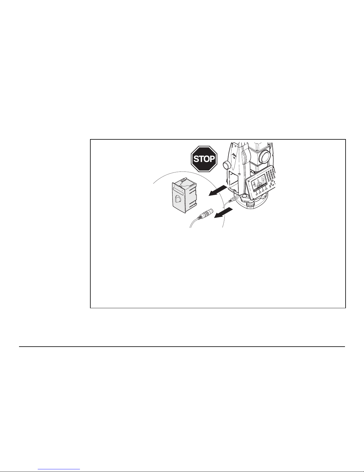
Warning
Do NOT remove the battery during operation of the
instrument, or during the shutdown procedure.
This can result in a file system error and data loss!
Always switch off the instrument by pressing the On/Off key,
and wait until the instrument has shutdown completely before
removing the battery.
TSOX_135

FlexLine, 6
Table of Contents
Table of Contents
In this manual Chapter Page
1 Description of the System 13
1.1 System Components 13
1.2 Container Contents 15
1.3 Instrument Components 17
2 User Interface 20
2.1 Keyboard 20
2.2 Screen 22
2.3 Status Icons 23
2.4 Softkeys 25
2.5 Operating Principles 26
2.6 Pointsearch 28
3 Operation 30
3.1 Instrument Setup 30
3.2 Working with the Battery 36
3.3 Data Storage 38
3.4 Main Menu 38
3.5 Q-Survey Application 40
3.6 Distance Measurements - Guidelines for Correct Results 41

Table of Contents FlexLine, 7
4 Setting 44
4.1 General Settings 44
4.2 EDM Settings 56
4.3 Communication Parameters 62
5 Tools 66
5.1 Adjust 66
5.2 Start Up Sequence 67
5.3 System Information 68
5.4 Licence Keys 70
5.5 Instrument Protection with PIN 71
5.6 Loading Software 73
6Functions 75
6.1 Overview 75
6.2 Target Offset 77
6.2.1 Overview 77
6.2.2 Cylinder Offset Subapplication 79
6.3 Hidden Point 83
6.4 Check Tie 85
6.5 EDM Tracking 87
6.6 Backsight Check 87
7Coding 89
7.1 Standard Coding 89

FlexLine, 8
Table of Contents
7.2 Quick Coding 91
8 Applications - Getting Started 93
8.1 Overview 93
8.2 Starting an Application 94
8.3 Setting the Job 95
8.4 Station Setup 97
9 Applications 99
9.1 Common Fields 99
9.2 Station Setup 100
9.2.1 Starting Station Setup 100
9.2.2 Measuring the target points 102
9.2.3 Station Setup Results 104
9.3 Surveying 108
9.4 Stakeout 110
9.5 Reference Element - Reference Line 116
9.5.1 Overview 116
9.5.2 Defining the Base Line 117
9.5.3 Defining the Reference Line 118
9.5.4 Subapplication Measure Line & Offset 121
9.5.5 Subapplication Stakeout 123
9.5.6 Subapplication Grid Stakeout 126
9.5.7 Subapplication Line Segmentation 130
9.6 Reference Element - Reference Arc 134
9.6.1 Overview 134

Table of Contents FlexLine, 9
9.6.2 Defining the Reference Arc 135
9.6.3 Subapplication Measure Line & Offset 138
9.6.4 Subapplication Stakeout 139
9.7 Tie Distance 144
9.8 Area & DTM Volume 147
9.9 Remote Height 154
9.10 Construction 156
9.10.1 Starting Construction 156
9.10.2 Layout 157
9.10.3 As Built Check 159
9.11 COGO 160
9.11.1 Starting COGO 160
9.11.2 Inverse and Traverse 161
9.11.3 Intersections 162
9.11.4 Offsets 165
9.11.5 Extension 167
9.12 Road 2D 167
9.13 Roadworks 3D 173
9.13.1 Starting Roadworks 3D 173
9.13.2 Basic Terms 175
9.13.3 Creating or Uploading Alignment Files 183
9.13.4 Subapplication Stake 186
9.13.5 Subapplication Check 189
9.13.6 Subapplication Stake Slope 191
9.13.7 Subapplication Check Slope 197

FlexLine, 10
Table of Contents
9.14 TraversePRO 199
9.14.1 Overview 199
9.14.2 Starting and Configuring TraversePRO 201
9.14.3 Measuring Traverse 204
9.14.4 Moving ahead 207
9.14.5 Closing a Traverse 210
9.15 Reference Plane 216
10 Data Management 220
10.1 File Management 220
10.2 Exporting Data 222
10.3 Importing Data 227
10.4 Working with a USB Memory Stick 231
10.5 Working with Bluetooth 233
10.6 Working with Leica FlexOffice 235
11 Check & Adjust 236
11.1 Overview 236
11.2 Preparation 237
11.3 Adjusting Line-of-Sight and Vertical Index Error 238
11.4 Adjusting the Tilting Axis Error 242
11.5 Adjusting the Circular Level of the Instrument and Tribrach 245
11.6 Inspecting the Laser Plummet of the Instrument 246
11.7 Servicing the Tripod 248

Table of Contents FlexLine, 11
12 Care and Transport 249
12.1 Transport 249
12.2 Storage 250
12.3 Cleaning and Drying 251
13 Safety Directions 252
13.1 General 252
13.2 Intended Use 252
13.3 Limits of Use 254
13.4 Responsibilities 254
13.5 Hazards of Use 255
13.6 Laser Classification 260
13.6.1 General 260
13.6.2 Distancer, Measurements with Reflectors 261
13.6.3 Distancer, Measurements without Reflectors
(Non-Prism mode) 263
13.6.4 Electronic Guide Light EGL 267
13.6.5 Laser Plummet 268
13.7 Electromagnetic Compatibility EMC 271
13.8 FCC Statement, Applicable in U.S. 274
14 Technical Data 276
14.1 Angle Measurement 276
14.2 Distance Measurement with Reflectors 277
14.3 Distance Measurement without Reflectors (Non-Prism mode) 279

FlexLine, 12
Table of Contents
14.4 Distance Measurement Reflector (>3.5 km) 281
14.5 Conformity to National Regulations 282
14.5.1 Products without Communication side cover 282
14.5.2 Products with Communication side cover 283
14.6 General Technical Data of the Instrument 284
14.7 Scale Correction 290
14.8 Reduction Formulas 293
15 International Limited Warranty, Software License Agreement 295
16 Glossary 297
Appendix A Menu Tree 301
Appendix B Directory Structure 304
Index 305

Description of the System FlexLine, 13
1 Description of the System
1.1 System Components
Main Components
a) FlexLine instrument with
FlexField firmware
b) Computer with FlexOffice
software
c) Data transfer
Component Description
FlexLine
instrument
An instrument for measuring, calculating and capturing data. Ideally
suited for tasks from simple surveys to complex applications.
Equipped with a FlexField firmware package to complete these
tasks.
The various lines have a range of accuracy classes and support
different features. All lines can be connected with FlexOffice to
view, exchange and manage data.
FlexField
firmware
The firmware package installed on the instrument. Consists of a
standard base operating system with optional additional features.
TSOX_001
a
c
b
Flex
Office

FlexLine, 14
Description of the System
FlexOffice
software
An office software consisting of a suite of standard and extended
programs for the viewing, exchanging, managing and post
processing of data.
Data transfer Data can be always transferred between a FlexLine instrument and
a computer via a data transfer cable.
For instruments equipped with a Communication side cover data
can also be transferred via USB memory stick, USB cable, or
Bluetooth.
Component Description
Description of the System FlexLine, 15
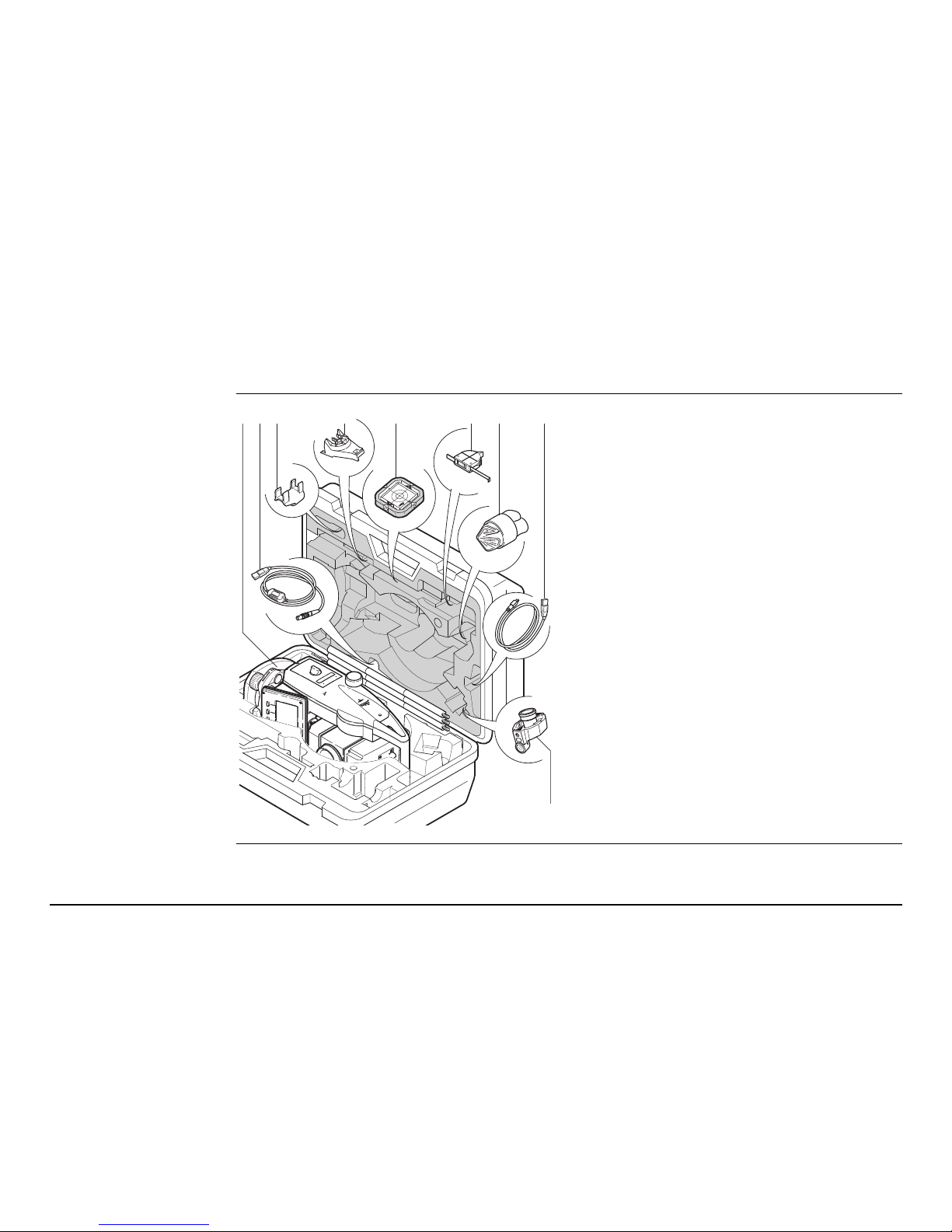
1.2 Container Contents
Container contents
part 1 of 2
a) Instrument with supplied tribrach
b) GEV189 data cable (USB-RS232)*
c) GLI115 clip-on bubble*
d) GHT196 holder for height meter*
e) CPR105 flat prism*
f) GHM007 height meter*
g) Protective cover / Lens hood*
h) GEV223 data cable (USB-mini USB) -
for instruments with a Communication side cover
i) GMP111 mini prism*
* Optional
TS0X_069a
ba c d e f g
i
h
FlexLine, 16
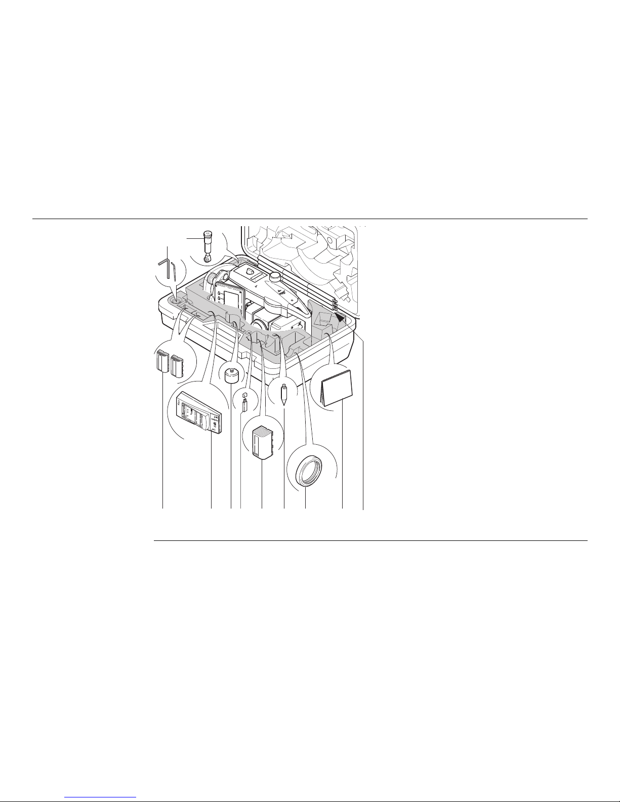
Description of the System
Container contents
part 2 of 2
j) Adjustment tools
k) GFZ3 diagonal eyepiece*
l) GEB211 batteries*
m) GKL211 battery charger*
n) GAD105 flat or mini prism adapter*
o) MS1 Leica industrial grade USB
memory stick - for instruments with a
Communication side cover
p) GEB221 battery*
q) Tip for mini prism pole*
r) Counterweight for diagonal
eyepiece*
s) User manual
t) GLS115 mini prism pole*
* Optional
TS0X_069b
jk
l
m n op q r s
t
Description of the System FlexLine, 17
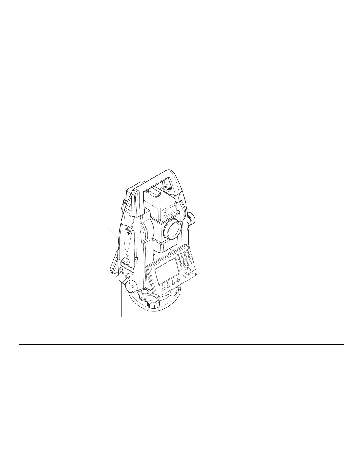
1.3 Instrument Components
Instrument
components
part 1 of 2
a) Compartment for USB memory stick
and USB cable ports*
b) Bluetooth antenna*
c) Optical sight
d) Detachable carrying handle with
mounting screw
e) Electronic Guide Light (EGL)*
f) Objective with integrated Electronic
Distance Measurement (EDM). Exit for
EDM laser beam
g) Vertical drive
h) On/Off key
i) Trigger key
j) Horizontal drive
k) Second keyboard*
* Optional
abcdfeg
j
kh i
TSOX_009a
FlexLine, 18
Description of the System
Instrument
components
part 2 of 2
l) Focusing telescope image
m) Eyepiece; focusing graticule
n) Battery cover
o) Serial interface RS232
p) Foot screw
q) Display
r) Keyboard
lm
no p q r
TSOX_009b

Description of the System FlexLine, 19
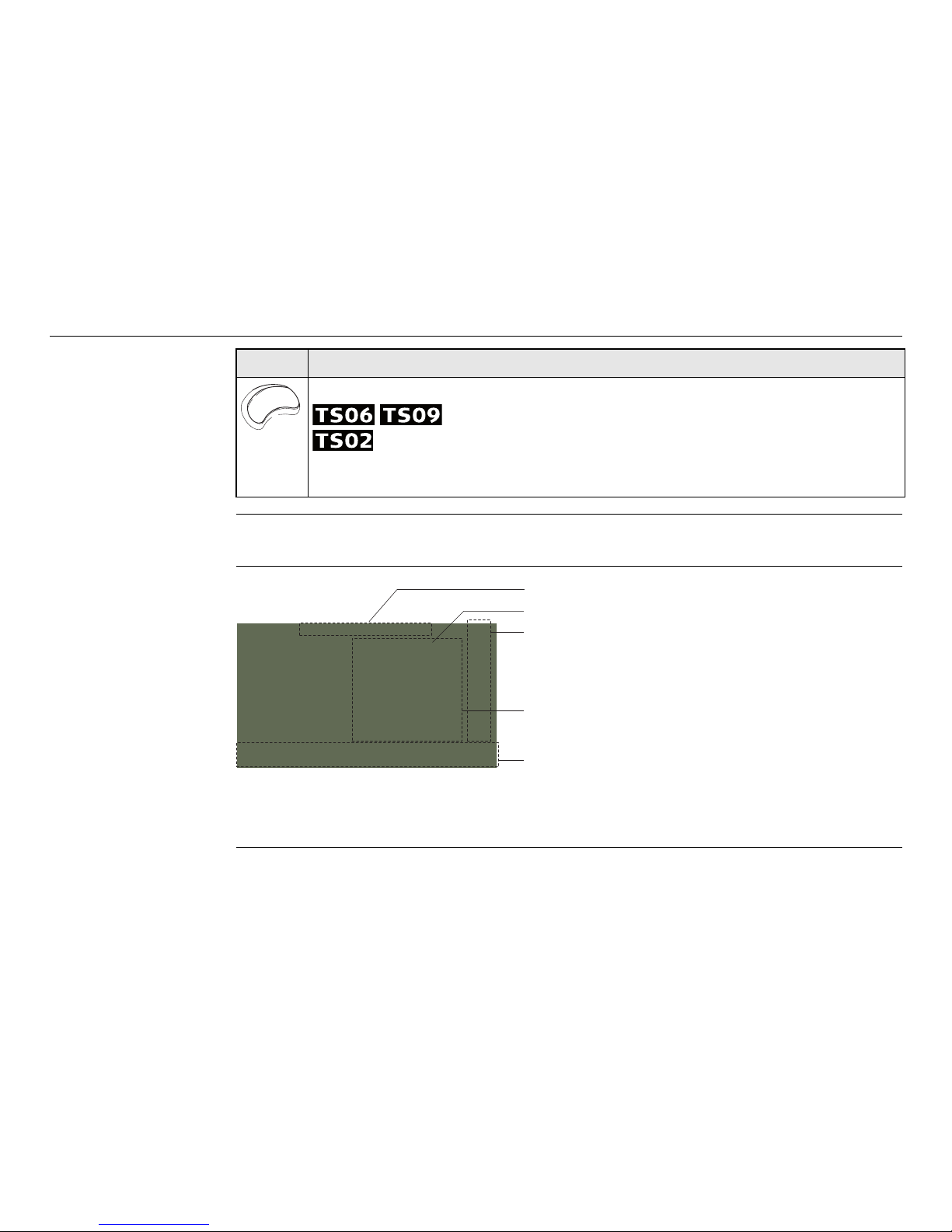
Communication
side cover
A Communication side cover is optional for and included for .
a) Bluetooth antenna
b) Compartment lid
c) USB memory stick cap storage
d) USB host port
e) USB device port
TSOX_130
a
b
c
d
e
FlexLine, 20
User Interface
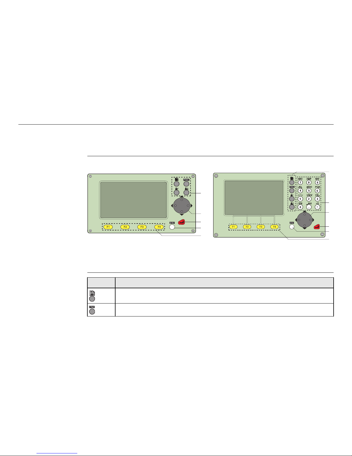
2 User Interface
2.1 Keyboard
Keyboard
Keys
Standard keyboard Alphanumeric keyboard
a) Fixed keys
b) Navigation key
c) ENTER key
d) ESC key
e) Function keys F1 to F4
f) Alphanumeric keypad
TSOX_011
a
b
c
d
e
TSOX_010
a
f
b
c
d
e
Key Description
Page key. Displays the next screen when several screens are available.
FNC key. Quick-access to measurement supporting functions.
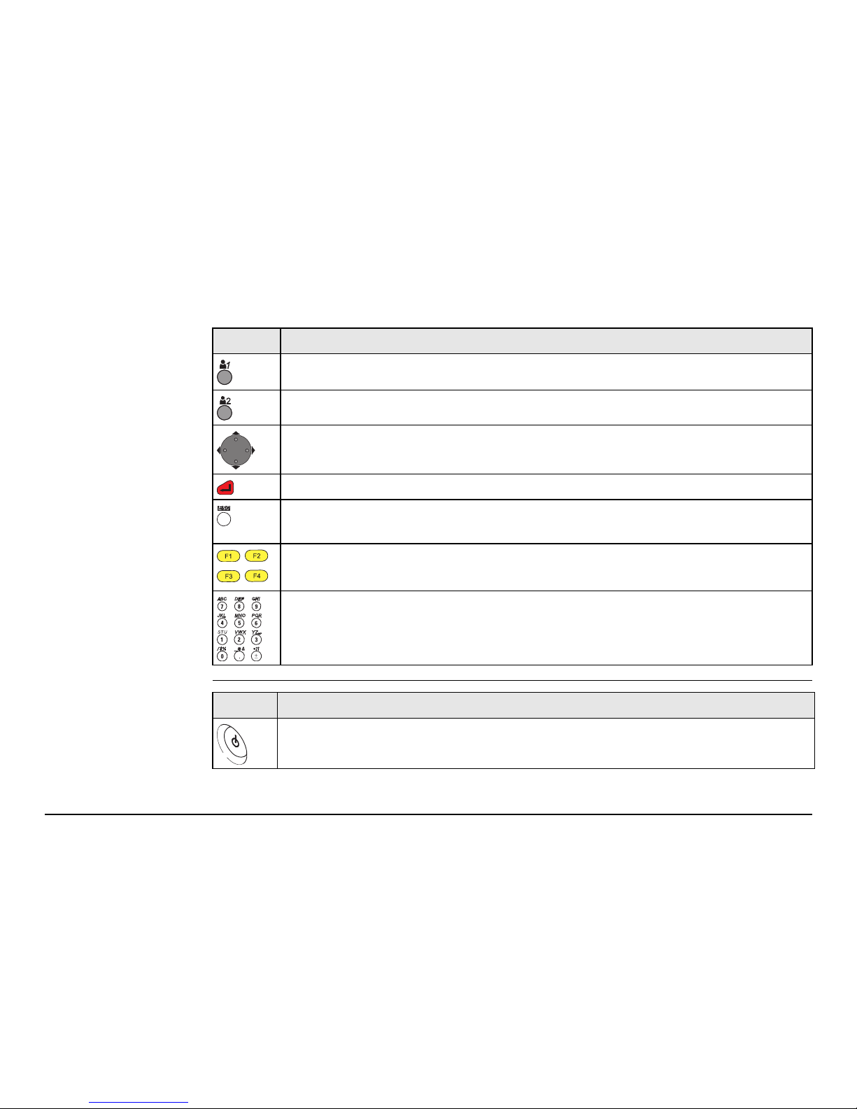
User Interface FlexLine, 21
Sidecover keys
User key 1. Programmable with a function from the FNC menu.
User key 2. Programmable with a function from the FNC menu.
Navigation key. Controls the focus bar within the screen and the entry bar
within a field.
ENTER key. Confirms an entry and continues to the next field.
ESC key. Quits a screen or edit mode without saving changes. Returns to
next higher level.
,,
,
Function keys that are assigned the variable functions displayed at the
bottom of the screen.
Alphanumeric keypad for entry of text and numerical values.
Key Description
Key Description
On / Off key. Switches the instrument on or off.
FlexLine, 22
User Interface
2.2 Screen
Screen
Trigger key. Quick key programmable with functions ALL or DIST, if desired.
Programmable with both of the functions.
Programmable with one of the functions.
The trigger key can be programmed in the Settings screen. Refer to "4.1
General Settings".
Key Description
a) Title of screen
b) Focus in screen. Active field
c) Status icons
d) Fields
e) Softkeys
All shown screens are examples. It is possible that local firmware versions
are different to the basic version.
a
b
c
d
e
S_TSOX_001

User Interface FlexLine, 23
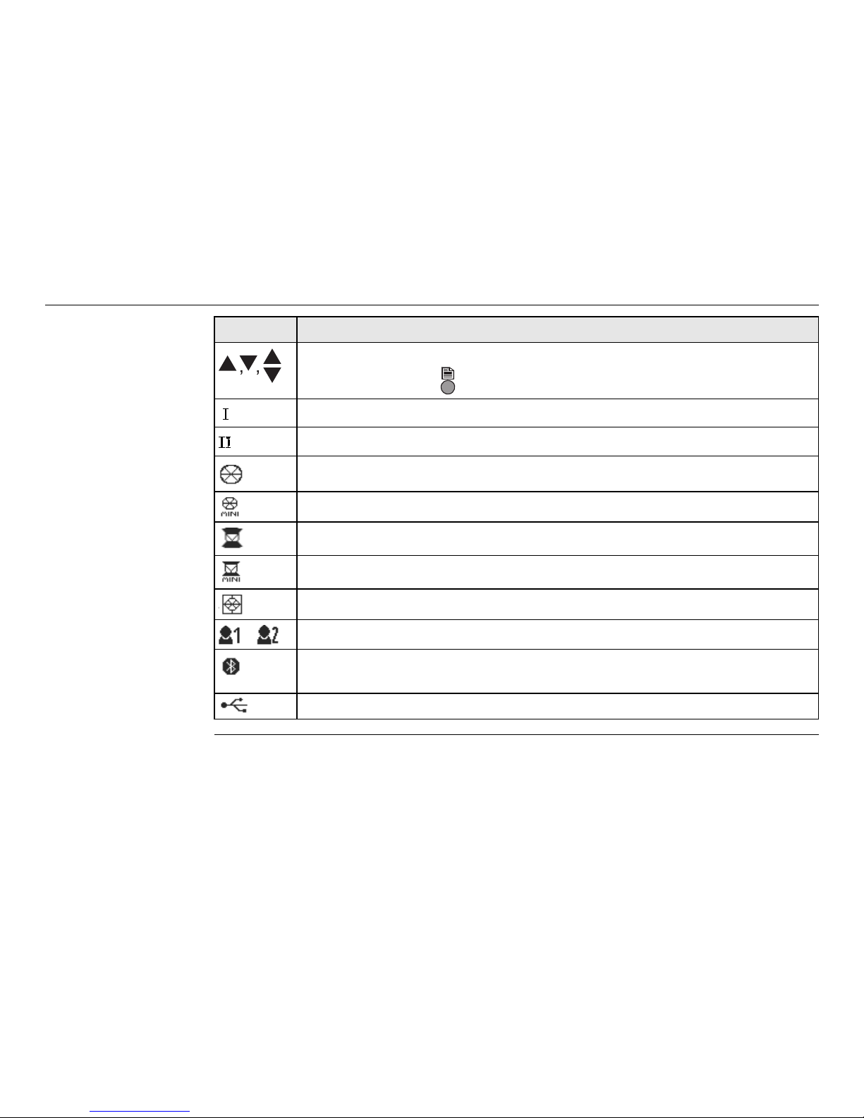
2.3 Status Icons
Description The icons provide status information related to basic instrument functions.
Depending on the firmware version, different icons are displayed.
Icons
Icon Description
The battery symbol indicates the level of the remaining battery capacity,
75% full shown in the example.
Compensator is on.
Compensator is off.
Prism EDM mode for measuring to prisms and reflective targets.
Non-Prism EDM mode for measuring to all targets.
! Offset is active.
Keypad is set to numeric mode.
Keypad is set to alphanumeric mode.
Indicates that horizontal angle is set to left side angle measurement
(anticlockwise).
A double arrow indicates a field has a selectable list.
012
ABC
FlexLine, 24
User Interface
Up and down arrows indicate that several screens are available, which
are accessed using .
Indicates telescope position is face I.
Indicates telescope position is face II.
Leica standard prism is selected.
Leica mini prism is selected.
Leica 360° prism is selected.
Leica 360° mini prism is selected.
Leica reflector tape is selected.
User defined prism is selected.
Bluetooth is connected. If there is a cross beside the icon, the Bluetooth
communication port is selected, but the status is inactive.
USB communication port is selected.
Icon Description

User Interface FlexLine, 25
2.4 Softkeys
Description Softkeys are selected using the relevant F1 to F4 function key. This chapter describes
the functionality of the common softkeys used by the system. The more specialised
softkeys are described where they appear in the application chapters.
Common softkey
functions
Key Description
-> ABC To change the keypad operation to alphanumerical.
-> 012 To change the keypad operation to numerical.
ALL To start distance and angle measurements and save the measured
values.
DIST To start distance and angle measurements without saving the measured
values.
EDM To view and change EDM settings. Refer to "4.2 EDM Settings".
ENH To open the manual coordinate entry screen.
EXIT To exit the screen or application.
FIND To search for an entered point.
INPUT
To activate alphanumerical softkeys for text entry.
P/NP To toggle between Prism and Non-Prism EDM modes.
LIST To display the list of available points.
FlexLine, 26
User Interface
2.5 Operating Principles
Turn instrument
on/off
Use the On/Off key on the side cover of the instrument.
Selection of
language
After switching on the instrument the user is able to choose their preferred language.
The language choice screen is only shown if multiple languages are loaded onto the
instrument and Lang.choice: On is set in the instrument settings. Refer to "4.1
General Settings".
OK If entry screen: Confirms measured or entered values and continues the
process.
If message screen: Confirms message and continues with selected action
or returns to the previous screen to reselect an option.
PREV To return to the last active screen.
REC To save the displayed values.
RESET To reset all editable fields to their default values.
VIEW To display the coordinate and job details of the selected point.
To display the next softkey level.
To return to the first softkey level.
Key Description

User Interface FlexLine, 27
Alphanumeric
keypad
The alphanumerical keypad is used to enter characters directly into editable fields.
• Numeric fields: Can only contain numerical values. By pressing a key of the
keypad the number will be displayed.
• Alphanumeric fields: Can contain numbers and letters. By pressing a key of the
keypad the first character written above that key will be displayed. By pressing
several times you can toggle through the characters.
For example: 1->S->T->U->1->S....
Standard keyboard To enter characters using a standard keypad, select INPUT and the softkeys will
change to represent the alphanumerical characters available in edit mode. Select the
appropriate softkey for entry of the character.
Edit fields
In edit mode the position of the decimal place cannot be changed. The decimal place
is skipped.
ESC Deletes any change and restores the previous value.
Moves the cursor to the left.
Moves the cursor to the right.
Inserts a character at the cursor position.
Deletes the character at the cursor position.

FlexLine, 28
User Interface
Special characters
2.6 Pointsearch
Description Pointsearch is a function used by applications to find measured or fixed points in the
memory storage.
It is possible to limit the point search to a particular job or to search the whole
storage. The search procedure always finds fixed points before measured points that
fulfill the same search criteria. If several points meet the search criteria, then the
results are ordered according to the entry date. The instrument finds the most recent
fixed point first.
Character Description
* Used as wildcards in search fields for point numbers or codes. Refer to
"2.6 Pointsearch".
+/- In the alphanumeric character set "+" and "-" are treated as normal
alphanumeric characters with no mathematical function.
"+" / "-" only appear in front of an entry.
In this example selecting 2 on an alphanumeric keyboard would start the Surveying
application.

User Interface FlexLine, 29
Direct search By entering an actual point number, for example 402, and pressing SEARCH, all
points within the selected job and with the corresponding point number are found.
Wildcard search The wildcard search is indicated by a "*". The asterisk is a place holder for any
following sequence of characters. Wildcards should be used if the point number is
not fully known, or to search for a batch of points.
Examples of point
searches
* All points are found.
A All points with exactly the point number "A" are found.
A* All points starting with "A" are found, for example, A9, A15, ABCD, A2A.
*1 All points containing only one "1" are found, for example, 1, A1, AB1.
A*1 All points starting with "A" and containing only one "1" are found, for
example, A1, AB1, A51.
SEARCH
To search for matching points within
the selected job.
ENH=0
To set all ENH coordinates for the
point ID to 0.
FlexLine, 30
Operation
3 Operation
3.1 Instrument Setup
Description This topic describes an instrument setup over a marked ground point using the laser
plummet. It is always possible to set up the instrument without the need for a
marked ground point.
Important features
• It is always recommended to shield the instrument from direct sunlight and avoid
uneven temperatures around the instrument.
• The laser plummet described in this topic is built into the vertical axis of the
instrument. It projects a red spot onto the ground, making it appreciably easier
to center the instrument.
• The laser plummet cannot be used in conjunction with a tribrach equipped with
an optical plummet.
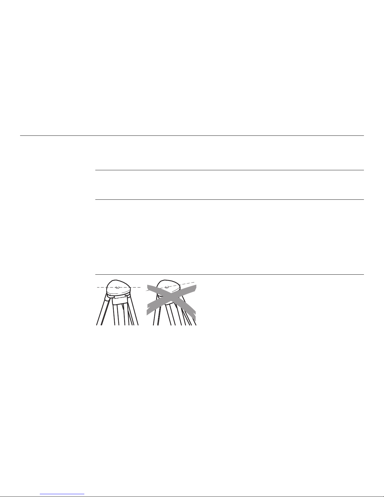
Tripod
When setting up the tripod pay attention
to ensuring a horizontal position of the
tripod plate. Slight corrections of inclination can be made with the foot screws of
the tribrach. Larger corrections must be
done with the tripod legs.
TSOX_012b
 Loading...