

Page 1
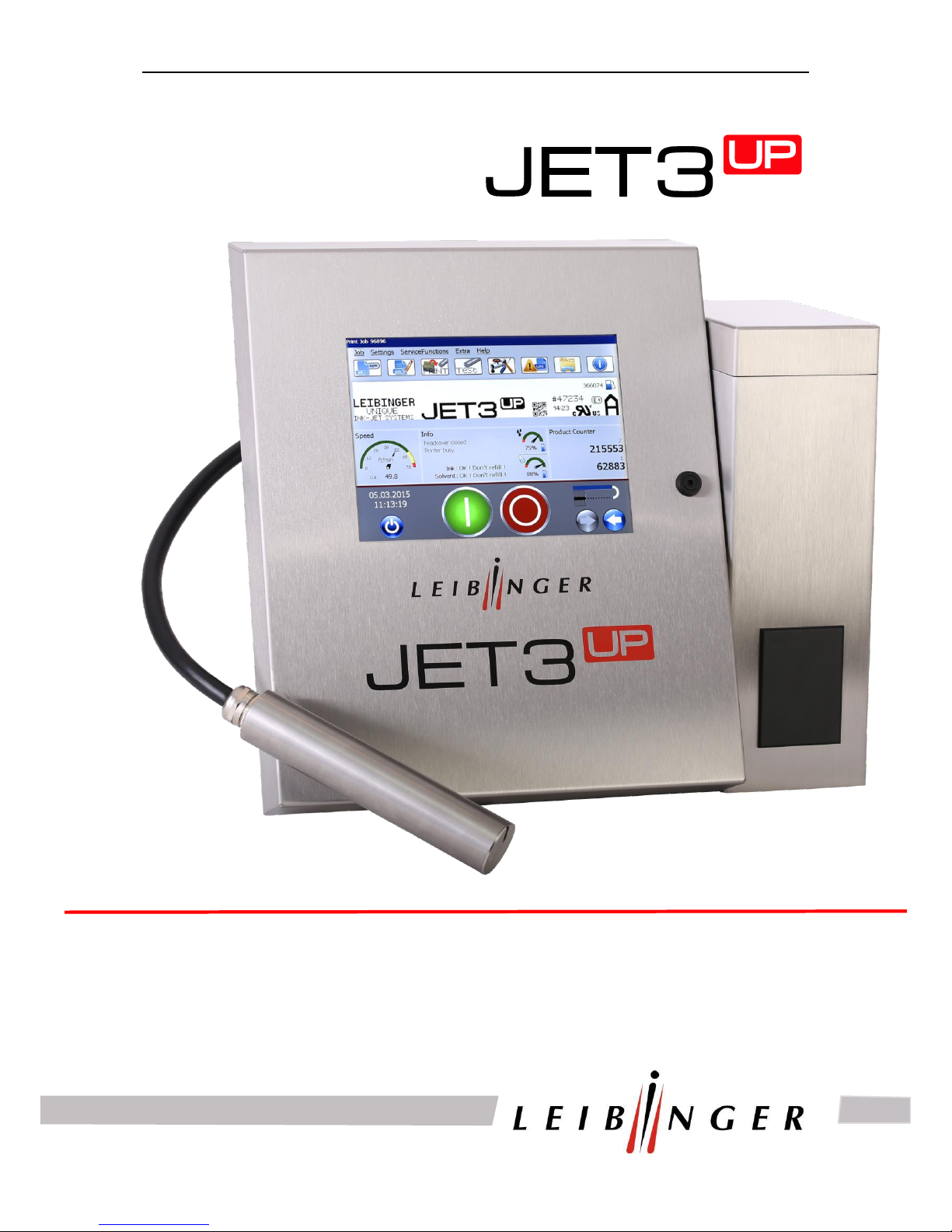
SERVICE MANUAL
Page 2

Service Manual JET3
2 Rev. 1.0
1 Introduction
1.1 Table of contents
1 Introduction ................................................................................................................. 2
1.1 Table of contents .................................................................................................... 2
1.2 Publisher ................................................................................................................. 5
1.3 Introduction ................................................................ ............................................. 7
1.4 Guarantee ............................................................................................................... 8
2 Safety ........................................................................................................................... 9
2.1 Scope of risks ......................................................................................................... 9
2.2 Safety instructions and recommendations ............................................................... 9
2.3 Intended use ......................................................................................................... 11
2.4 Safety sticker ........................................................................................................ 12
2.5 Operating staff ...................................................................................................... 13
2.6 Dangers due to electric energy ............................................................................. 13
2.7 Personal protective equipment .............................................................................. 13
2.8 Protective devices and safety concept .................................................................. 13
2.9 Safety measures at the place of installation .......................................................... 14
2.10 Prior to assembly the place of setting up must be cleaned of dirt and contamination
(residue of lubricants etc.). The working place surroundings should be kept clean at all
times in order to ensure unrestricted access to the JET3up device. ................................. 14
2.11 Dangers through consumables ............................................................................. 15
2.12 Conformity ............................................................................................................ 16
3 Accident prevention .................................................................................................. 17
3.1 Storage and handling (normal use) ....................................................................... 17
3.2 First aid measures ................................................................................................ 18
3.3 Fire fighting measures .......................................................................................... 18
3.4 Measures in the event of accidental release (spillage) .......................................... 19
4 Technical data ........................................................................................................... 20
4.1 Dimensions, weights, connections ........................................................................ 20
4.2 Electrical connection values .................................................................................. 21
4.3 Ambient conditions ................................................................................................ 21
Page 3

Service Manual JET3
Rev. 1.0 3
5 Transport/Start up (Putting into service) ................................................................. 22
5.1 Transport, storage, shipping ................................................................................. 22
5.2 Mounting ............................................................................................................... 22
5.3 Installation............................................................................................................. 24
5.3.1 Mains supply ................................................................................................ 24
5.3.2 Grounding (Potential equalization) ............................................................... 24
5.3.3 Explosion protection ..................................................................................... 26
5.3.4 Print head ..................................................................................................... 26
6 Trouble shooting ....................................................................................................... 28
6.1 Trouble shooting ................................................................................................... 28
7 Service works ............................................................................................................ 56
7.1 Service TAG ......................................................................................................... 56
7.2 Documentations for ............................................................................................... 58
1) Cleaning of print head .................................................................................. 59
2) Cleaning of print head/electrode block with special cleaner 77001-00020 .... 60
3) Cleaning of nozzle with special cleaner 77001-00020 ................................... 64
4) Print head adjustment .................................................................................. 69
5) Exchange the oscillator ................................................................................ 75
6) Exchange gutter tube ................................................................................... 83
7) Exchange suction tube on print head............................................................ 87
8) Exchange the electrode block ...................................................................... 93
7.3 Documentations for ............................................................................................... 99
SK6 .................................................................................................................................. 99
1) Cleaning of print head .................................................................................100
2) Cleaning of print head/electrode block with special cleaner 77001-00020 ...101
3) Removing and cleaning the nozzle ..............................................................105
4) Print head adjustment .................................................................................109
5) Exchange oscillator .....................................................................................113
6) Exchange head motor .................................................................................117
7) Exchange gutter tube ..................................................................................123
8) Exchange suction tube on print head...........................................................131
9) Exchange the electrode block .....................................................................137
Page 4

Service Manual JET3
4 Rev. 1.0
7.4 Hydraulic ............................................................................................................. 144
1) Hydraulic scematic ......................................................................................144
2) Deplete routine ............................................................................................145
3) Exchange valve block ..................................................................................150
7.5 Electronics .......................................................................................................... 158
1) Save data log-file.........................................................................................158
2) Save info .....................................................................................................161
3) Save prod. history file ..................................................................................164
4) Exchange power supply ..............................................................................166
5) Exchange touch display...............................................................................171
6) Exchange the controller board .....................................................................182
7) Adjust the service interval ............................................................................209
8) Exchange the fan for the electronic cabinet .................................................211
Page 5

Service Manual JET3
Rev. 1.0 5
1.2 Publisher
For questions regarding the operation and running of the as well as in service case please
contact the listed dealer address.
Dealer address
Paul Leibinger GmbH & Co. KG
Marking&Coding Systems
Daimlerstraße 14
D-78532 Tuttlingen
Federal Republic of Germany
Phone +49 74 61/92 86-0
Fax +49 74 61/92 86-1 99
E-mail: [email protected]
Service hotline phone +49 74 61/92 86-8 63
Service hotline fax 0 74 61/92 86-8 69
Service hotline e-mail: [email protected]
American Branch Office
Paul Leibinger
Numbering Machine LTD
2702-B Buell Drive
East Troy, WI 53120 USA
Tel.+01 262.642-4030
Fax.+01 262.642.4033
email: [email protected]
Page 6

Service Manual JET3
6 Rev. 1.0
We reserve all rights, in particular the right to translate, distribute and reproduce. No part of
this manual must be reproduced or distributed and stored through the use of electronic data
processing systems or made accessible to third parties in any form (redrawn, photocopied,
microfilmed or through any other process) without the written consent of the publisher.
We reserve the right to make alterations to the scope of delivery at any time in the form of
technology, hardware, software as well as the corresponding materials (and manual extracts)
as a result of innovative further development of our devices.
Texts, illustrations and technical drawings have been compiled with the greatest of care.
Nevertheless errors cannot be excluded. Consequently no guarantee can be assumed for
the correctness of the content of this manual and no claims can be asserted against Paul
Leibinger GmbH & Co. KG.
We shall be grateful for information regarding possible printing errors as well as for
suggestions for the further optimisation of the device manual.
Authoritative for the scope of delivery is not the manual but rather the written order
confirmation.
Page 7
Service Manual JET3
Rev. 1.0 7
1.3 Introduction
We are pleased that you have decided in favour of a device and welcome you as one of our
customers.
You now own a device that has been developed and constructed on the basis of many years
of experience and using the latest Leibinger technology. This results in a high degree of
quality and the renowned Leibinger reliability.
This manual shows you the fundamental advantages of the Leibinger Jet system
manufactured by us, such as for example the fully automatic working, low maintenance etc..
The manual must be read thoroughly prior to first start up in order to
ensure that no damage to the device and/or endangering of the operating
personnel results from a defective electrical connection and/or from
incorrect operation.
Please pay particular attention to the safety instructions of the groups
Safety instructions and accident prevention when handling
consumables (ink and solvent).
Our devices are subjected to a quality control in our plant prior to delivery. If despite this the
device or parts of it should be damaged or their function disturbed please advise us of this as
fast as possible.
It is only through the use of inks and solvents from Paul Leibinger GmbH & Co. KG that
optimum operating characteristics can be achieved. Should other inks and solvents be
used all guarantee claims will expire.
Product liability!
No alterations whatsoever must be carried out on the entire device.
No liability will be accepted for damage or dangers resulting from
inadmissible alterations.
Attention – Danger of explosion!
The device should be only operated outside of explosive areas!
The installation has to be carried out according to the installation
instructions of the manufacturer!
Page 8

Service Manual JET3
8 Rev. 1.0
1.4 Guarantee
The guarantee conditions for the JET3up can be seen from the order confirmation. The
warranty presuppose that the device or the installation is operated correctly in accordance
with the available guarantee manual and any possible additional manuals and descriptions
prepared by us.
At this point we wish to make explicit reference to the fact that it is only when using solvent
and ink from Paul Leibinger GmbH & Co. KG that the optimum operating characteristics can
be achieved.In the event of use of other inks and solvents all guarantee entitlements
shall cease to apply.
Page 9
Service Manual JET3
Rev. 1.0 9
2 Safety
2.1 Scope of risks
The high performance printer has been built in accordance with state-of-the-art standards
and recognized safety requirements and has been equipped with protective devices.
Operational and safety checks of the installation were carried out before it left the factory. In
case of improper handling or misuse, however, there are dangers for
the health of the operating staff
the high performance printer and other real assets of the plant operator
the efficient operation of the high performance printer
All persons entrusted with the putting into service, the operation, the maintenance and the
overhauling of the high performance printer must
have the necessary qualification and
strictly comply with this operating manual.
YOUR safety matters!
2.2 Safety instructions and recommendations
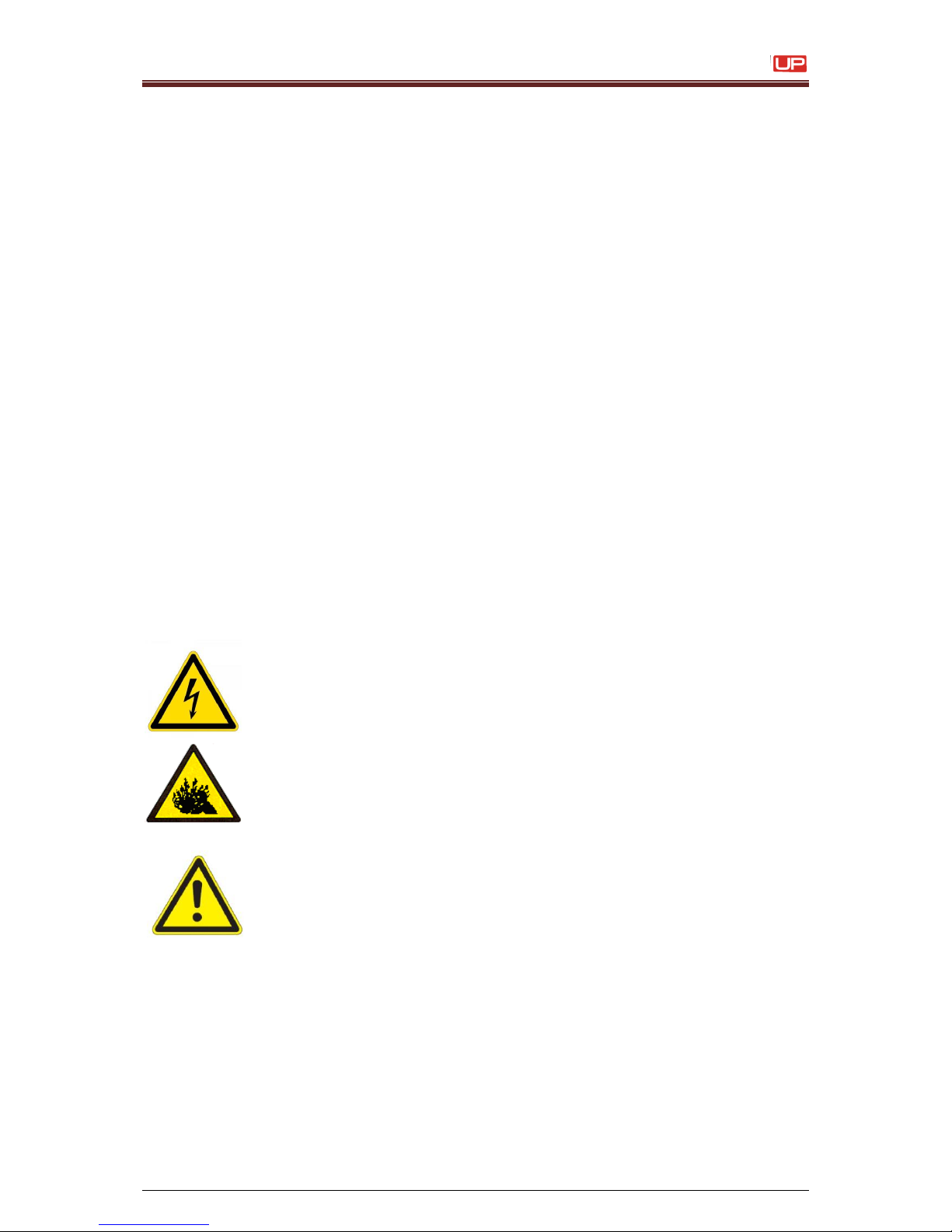
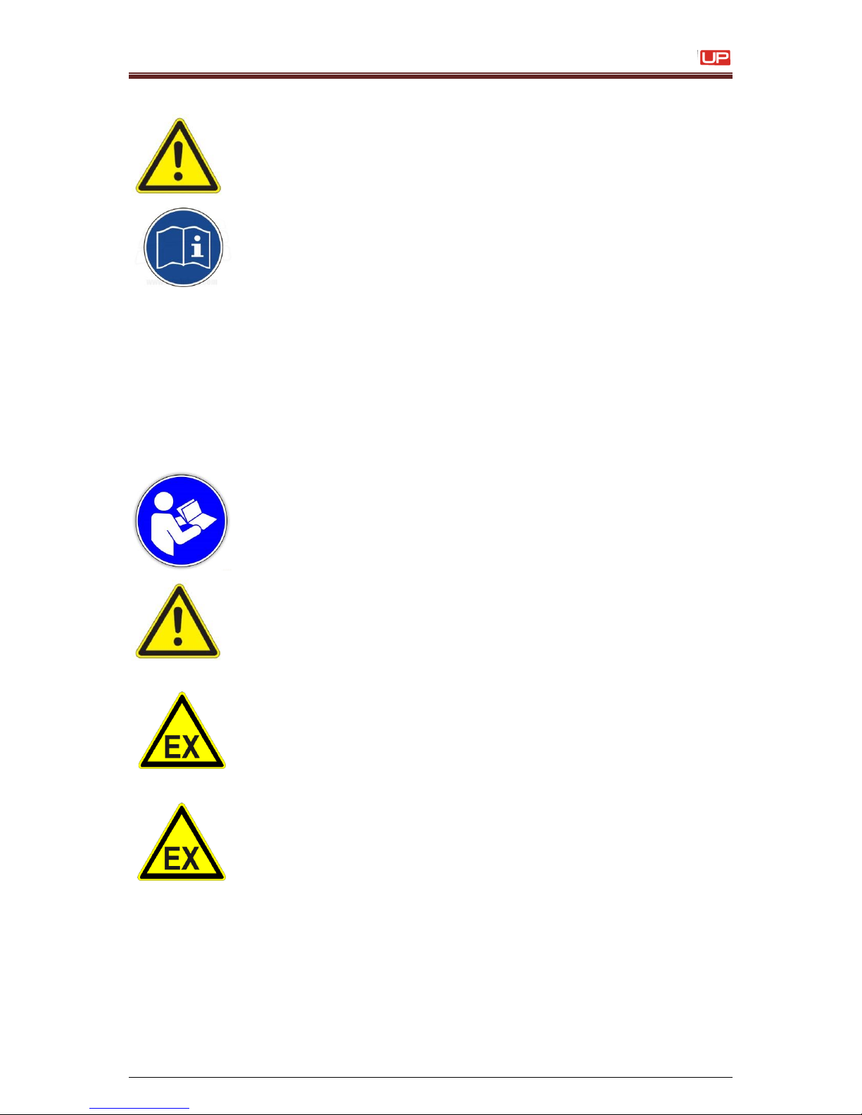
This operating manual use the following SYMBOLS with DANGER WARNINGS:
Indicates impending electrical danger!
Failure to observe this instruction can lead to serious injuries or to death!
Indicates a dangerous situation through pressurised media!
Failure to observe this instruction can cause injuries!
Indicates a dangerous situation!
Failure to observe this instruction can lead to material damage or to
injuries!
Page 10
Service Manual JET3
10 Rev. 1.0
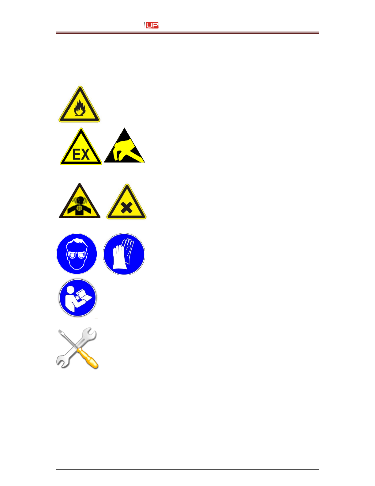
Indicates a dangerous situation!
Failure to observe this instruction can cause serious hand injuries!
Indicates a dangerous situation through flammable materials!
Failure to observe this instruction can lead to material damage, to serious
burns or to death!
Describes a dangerous situation by an explosive
atmosphere and/or by an electrostatic discharge!
The non-observance of this advice can cause explosions
and therefore damages to property, serious burnings or
serious damages to person!
Indicates a dangerous situation through irritating
materials!
Failure to observe this instruction can lead to poisoning
and to irritation of the eyes, the skin as well as of the
respiratory organs!
Indicates the necessity of personal protective
clothing!
Sufficient protective equipment must be worn. Failure to
observe this instruction can lead to injury!
Indicates the necessity of observing the device
manual and other instructions!
Failure to observe this instruction can lead to material
damage, the loss of guarantee and to injury!
Indicates service activities!
This work must only be carried out by trained personnel or by Leibinger
service technicians!
Page 11
Service Manual JET3
Rev. 1.0 11
Indicates important user information
for safe and effective working.
Indicates recommendations for use
and other useful pieces of information.
2.3 Intended use
The high performance printer serves exclusively the contact-free marking, inscribing and
coding of surfaces using the continuous ink jet process.
The high performance printer can be used on the most varying materials (e.g. metal,
synthetic material, Glassss, paper, wood, pressed materials, rubber etc.) with both, smooth
as well as uneven, rough and stepped surfaces.
The intended use of this device also includes the observance of all
instructions in this manual.
Using the installation for other purposes is considered contrary to
its intended use!
For safety reasons conversions and alterations are only admissible
following consultation with the manufacturer. Repairs to the device must
only be carried out with original replacement parts.
The manufacturer shall not be liable for damage resulting from use for
other than the intended purpose or misuse.
Attention – Danger of explosion!
The device should be only operated outside of explosive areas! The
installation has to be carried out according to the installation
instructions of the manufacturer!
Attention – Danger of explosion!
Precautions regarding electrostatics have to be carried out!
Page 12
Service Manual JET3
12 Rev. 1.0
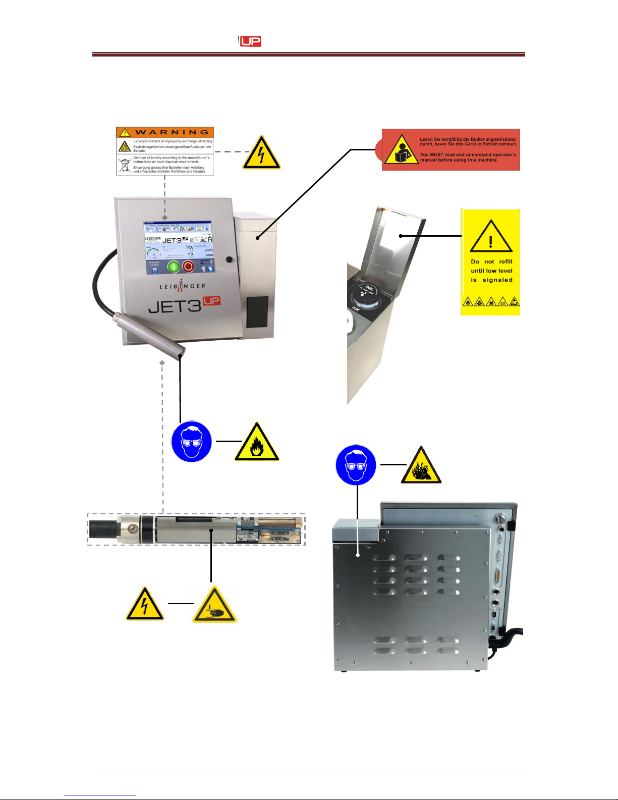
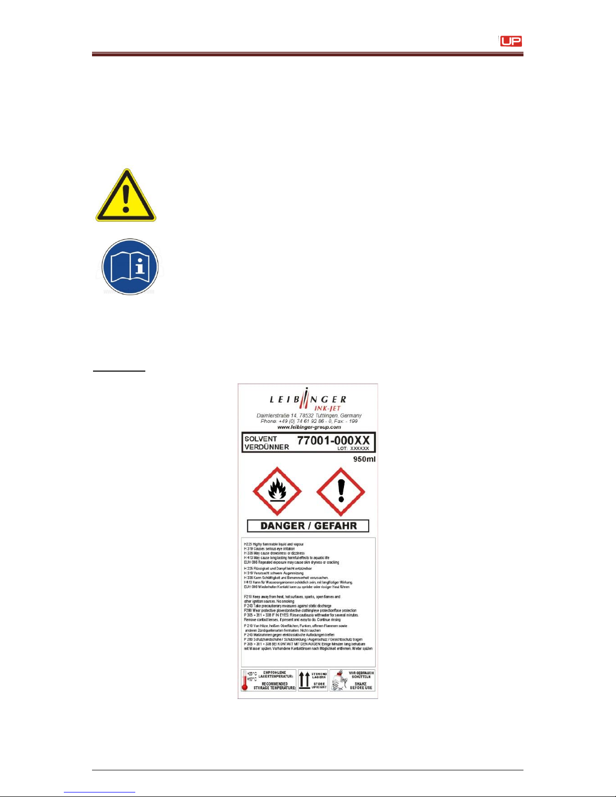
2.4 Safety sticker
Figure 1
Page 13
Service Manual JET3
Rev. 1.0 13
2.5 Operating staff
Only trained personnel must operate the device. The personnel must have appropriate
training to enable them to be able to operate the JET3up high performance printer
professionally.
Within the working area of the up device the operator is responsible with regard to third
parties.
The operator must
put this operating manual at the operating staff’s disposal and
make sure that they have read and understood them.
2.6 Dangers due to electric energy
The electrical and electronic components of the high performance printer
are under voltage. The device must only be opened by trained personnel
or by Leibinger service technicians.
Prior to the opening of the device the device must be switched off and the
mains plug removed.
2.7 Personal protective equipment
Materials are processed in this device that cause irritations and which are under pressure. In
order to avoid injury and damage the personnel must wear the following personal protective
equipment during certain work procedures:
suitable work clothing
suitable eye protection
suitable hand protection
More detailed information can be found in the corresponding chapters of this manual as well
as possibly in information and data leaflets of consumables.
2.8 Protective devices and safety concept
In an emergency the device is placed idle by removal of the mains plug.
The device is equipped with the following safety concept to provide explosion protection:
Bottom tub as collecting tray
Jet monitoring in the gutter circuit
Page 14
Service Manual JET3
14 Rev. 1.0
Ventilation in the hydraulic cabinet
HV-cutoff at creepage current
Plastic containers are arranged in the
field of metal surfaces (PE-potential)
HV- and ink cutoff as well as nozzle sealing
at HV-flashovers
2.9 Safety measures at the place of installation
Mains connection!
The device has no mains switch and must only be connected to a
easy accessible plug socket in the direct vicinity of the place of
setting up!
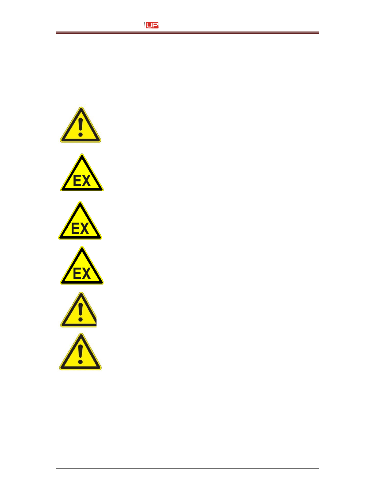
Attention – Danger of explosion!
The device should be only operated outside of explosive areas! The
installation has to be carried out according to the installation
instructions of the manufacturer!
Attention – Danger of explosion!
The device has to be integrated in the lightning protection concept
of the operator!
Attention – Danger of explosion!
Precautions regarding electrostatics have to be carried out!
Installation of the device
The device must be installed in a well ventilated room only and must
be kept away from any source of heat, flame or sparks, e.g. radiant
heater, etc.
A place of setting up must be selected with sufficient load bearing
capacity and stability. When setting up it must be observed that sufficient
movement space is available for the operating and service personnel.
Solvents are processed in the device, sufficient room ventilation must be
ensured!
2.10 Prior to assembly the place of setting up must be cleaned
of dirt and contamination (residue of lubricants etc.). The
working place surroundings should be kept clean at all
times in order to ensure unrestricted access to the
JET3up device.
Page 15
Service Manual JET3
Rev. 1.0 15
2.11 Dangers through consumables
Inks are coloured liquids on a solvent basis. The safety instructions on the containers of the
consumables as well as the instructions in the group Accident prevention must be
especially adhered to in order to exclude dangers for persons and the surroundings. Further
instructions can be found in the Safety Data Sheets.
When handling consumables (inks/solvents) the danger instructions and
safety advice on the containers (transport, storage, distribution and
correct disposal) must be observed!
In addition we recommend observance of the safety information
leaflets of the inks and solvents used.
In the following you will find examples for the marking of inks and solvents.
Figure 2
Examples: Labels for the marking of inks and solvents.
Page 16

Service Manual JET3
16 Rev. 1.0
2.12 Conformity
Extract of declaration of conformity
according to machinery directive (2006/42/EG), Appendix II 1.A
according to low-voltage directive (2006/95/EG)
according to EMC directive (2004/108/EG)
complies with the provisions of the above mentioned directives –including the changes which
valid at that time of the declaration. The following harmonized standards have been applied:
DIN EN ISO 12100
Safety of machinery – General principles for design – Risk
assessment and risk reduction
DIN EN 60950-1
Information technology equipment – Safety;
part 1: General requirements
DIN EN ISO 13732-1
Ergonomics for the thermal environment – Methods for the
assessment of human responses to contact with surfaces;
part 1: Hot surfaces
EN 61000-6-2
Electromagnetic compatibility (EMC) – part 6-2:
Generic standards – Immunity for industrial environments
EN 61000-6-3
Electromagnetic compatibility (EMC) – part 6-3:
Generic standards – Emission standard for residential,
commercial and light-industrial environments
For that product the relevant technical documentation were compiled according to Annex VII
part A of the machinery directive, on a resend request this documents can be transmitted to
national authorities per CD.
Name and address of the person who is authorised to arrange the technical documentation:
Volker Teufel, authorised documentation agent,
Paul Leibinger GmbH & Co. KG, D-78532 Tuttlingen (Germany)
Annotation:
The device fulfills the fundamental health and safety requirements of the directive 94/9/EU,
but is intended only for use outside of explosive areas. This declaration is only valid for the
components which are included in the delivery range of the manufacturer. The installation
and works which have been carried out by the customer either the distributor as well as it's
components and modules are not the responsibility of the manufacturer. The adherence of
the valid standards and regulations of the technology are generally the responsibility of the
customer either of the distributor.
Page 17

Service Manual JET3
Rev. 1.0 17
3 Accident prevention
The following presentation shows the measures in the event of an accident with ink and
solvent with the danger marking,
slightly ignitable
irritates the eyes and the respiratory organs.
3.1 Storage and handling (normal use)
GENERAL
These products must only used at points that are free from open
flames and other ignition sources. Do not use pressure for
emptying – the container is not a pressure vessel. Good household
practice and regular, safe removal of the waste materials restrict
the danger of self-ignition and other risks of fire to a minimum. The
product can charge statically. When pouring from one container to
another use a mass lead. The workers must wear anti-static shoes
and clothing and the floors must be conductive.
STORAGE
Observe the marking information. Store at 5 to 25°C in a warm, well
ventilated location at a safe distance from heat and ignition sources
and direct sunlight.
Do not smoke! Do not grant access to unauthorised persons.
Open containers must be properly closed and stored upright in
order to avoid leakage.
Smoking, eating and drinking must be forbidden in the storage and
working areas. Always keep in containers from the same material
as the delivery containers.
HANDLING
The development of combustible or explosive vapour concentrations must be prevented and vapour concentrations avoided that
are above the threshold values of the employers liability insurance
association. Keep containers closed tightly.
Keep sources of heat and sparks as well as open flames well away.
Use only spark-free tools. Electrical devices must be protected in
accordance with the corresponding standard.
Avoid contact with the skin and eyes. Do not inhale vapours and
spray mist.
Page 18

Service Manual JET3
18 Rev. 1.0
3.2 First aid measures
EYES
Contact lenses must be removed. Rinse thoroughly with pure,
fresh water for at least 10 minutes, keep eyelids spread and call
a doctor.
SKIN
Remove contaminated clothes. Wash skin thoroughly with soap
and water or with a branded skin cleansing agent. DO NOT use
solvents or thinners.
INHALING
Take patient into the fresh air and keep warm and calm. In the
event of irregular breathing or of breath being missed
resuscitate artificially. Do not give anything orally, place
unconscious patients on their side and call a doctor.
MISCELLANEOUS
In case of doubt or with persistent symptoms call a doctor.
Never give anything orally to unconscious patients.
3.3 Fire fighting measures
EXTINGUISHING
AGENTS
Recommended:
Alcohol-resistant foam, spray water/mist, CO2 or
powder
DO NOT use water jets. Cool closed containers exposed to the
fire with spray water.
RISK OF FIRE
AND EXPLOSION
As the product contains combustible organic constituents, a thick,
black smoke develops in the event of fire that contains dangerous
combustion products. Decomposition products can constitute a
danger to health. Extinguishing waste water must not enter the
waste water channels or waters.
PROTECTIVE
MEASURES
If necessary suitable, independent breathing apparatus is
required.
Page 19

Service Manual JET3
Rev. 1.0 19
3.4 Measures in the event of accidental release (spillage)
PRECAUTIONARY
MEASURES
Switch off sources of ignition and ventilate room. Keep personnel
that is not absolutely necessary away. Do not inhale any vapour.
Observe the protective measures listed.
ENVIRONMENTAL
PROTECTION
MEASURES
DO NOT allow to enter waste water channels or waters.
Should the product enter waste water channels or the drainage
system the local water supply authority must be informed
immediately. In the event of contamination of streams, rivers or
lakes inform the national water authorities. Vapour is heavier than
air and can spread out on the ground. In combination with air it can
form an explosive mixture.
RESTORATION
Restrict and suck up spilled substances with a non-combustible
absorbent material (e.g. sand, earth, vermiculite, infusorial earth)
and collect in a suitable container for removal. Preferably clean
areas with spilled substances with a detergent. Avoid solvents.
Page 20
Service Manual JET3
20 Rev. 1.0
4 Technical data
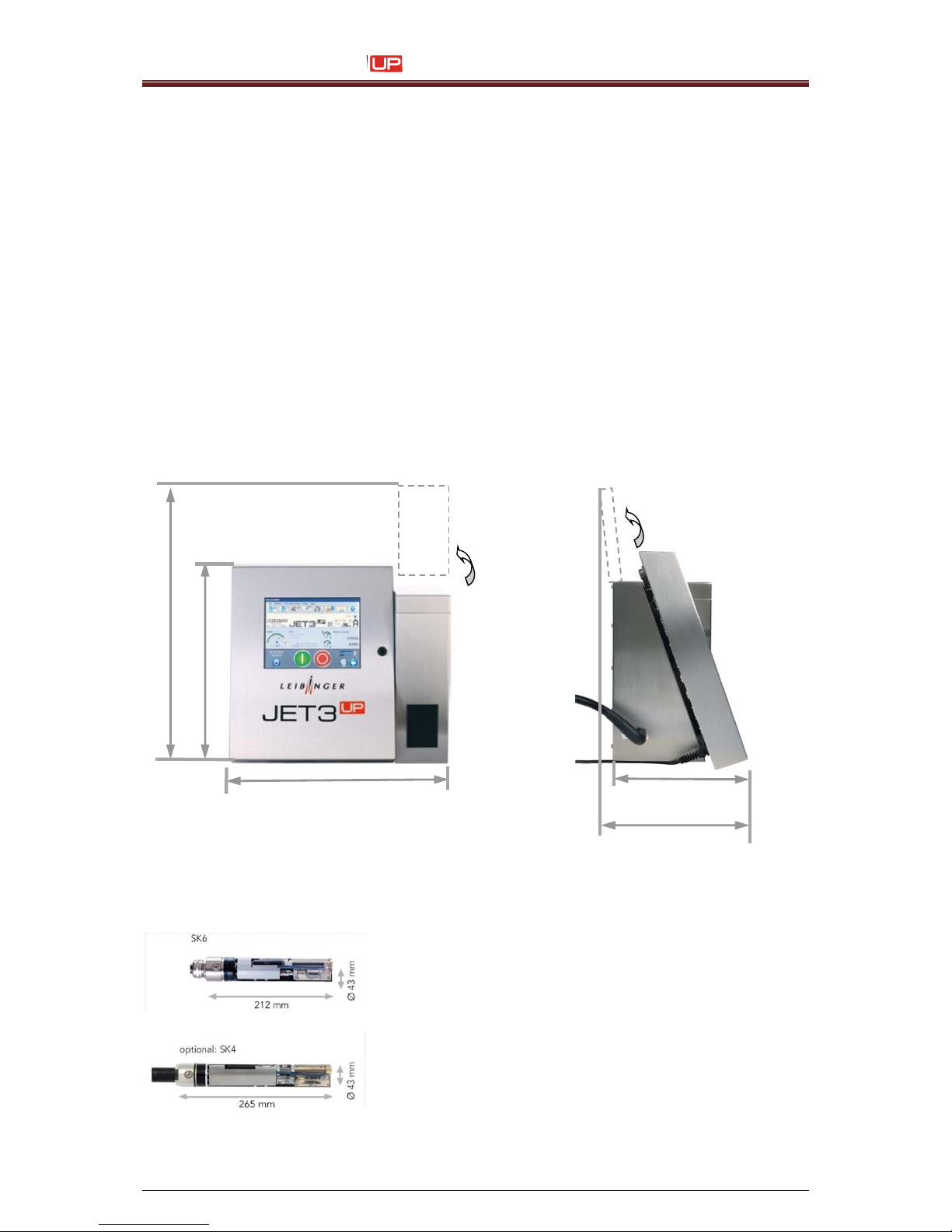
4.1 Dimensions, weights, connections
Cabinet :
Stainless steel
Width 486 mm, depth 286 mm, height 446 mm
Weight: 20,5 kg
Print head:
Stainless steel cabinet
Length (total) 265 mm, diameter 43 mm,
Length of the print head lead 3 m, as option 6 and 10 m available
Weight: 1,5 kg
Any fitting position, also for overhead conveyor applications
Figure 3
Protection class:
IP 54 (as option: IP 65)
286 mm
344 mm
486 mm
446 mm
565 mm
Page 21

Service Manual JET3
Rev. 1.0 21
4.2 Electrical connection values
Input voltage (voltage range):
100 - 240 V AC ,50-60 Hz
Current consumption:
max. 0,56 A at 100 V AC
max. 0,25 A at 240 V AC
Power consumption:
typ. 20 W at 100 V AC
typ. 20 W at 240 V AC
4.3 Ambient conditions
Temperature range:
+ 5° C to + 45° C (no rapid change of temperature)
Relative humidity:
max. 90 % relative humidity (non-condensating)
Page 22
Service Manual JET3
22 Rev. 1.0
5 Transport/Start up (Putting into service)
5.1 Transport, storage, shipping
In order to avoid damage during transport the following instructions must be observed.
The JET3up must only be transported in a standing position. It is packed in a cardboard box
with special polystyrene inserts for safe dispatch during delivery. Transport of the device
must only be made in this packing in order to avoid damage.
The printer should be only transported in an empty condition!
A special draining routine (“ServiceFunctions Hydraulic Special
Functions/ Tools Drain Routine“) is available for the draining of the
device.
You will find further information in the group Data input/Programming in
the chapter Draining routine!
Note! Storage temperatures below +5°C and above +50°C as well as storage at outside are
not admissible and can lead to damage!
5.2 Mounting
Attention – Danger of explosion!
The device should be only operated outside of explosive areas! The
installation has to be carried out according to the installation instructions
of the manufacturer!
Attention – Danger of explosion!
Precautions regarding electrostatics have to be carried out!
Installation of the device
The device must be installed in a well ventilated room only and must be
kept away from any source of heat, flame or sparks, e.g. radiant heater,
etc..
Check device for damage! When determining a suitable place of setting up, the necessary
additional space requirement for the movement room of the operating and service personnel
must be taken into consideration. Solvents are processed in the device, adequate room
ventilation must be ensured!
Page 23
Service Manual JET3
Rev. 1.0 23
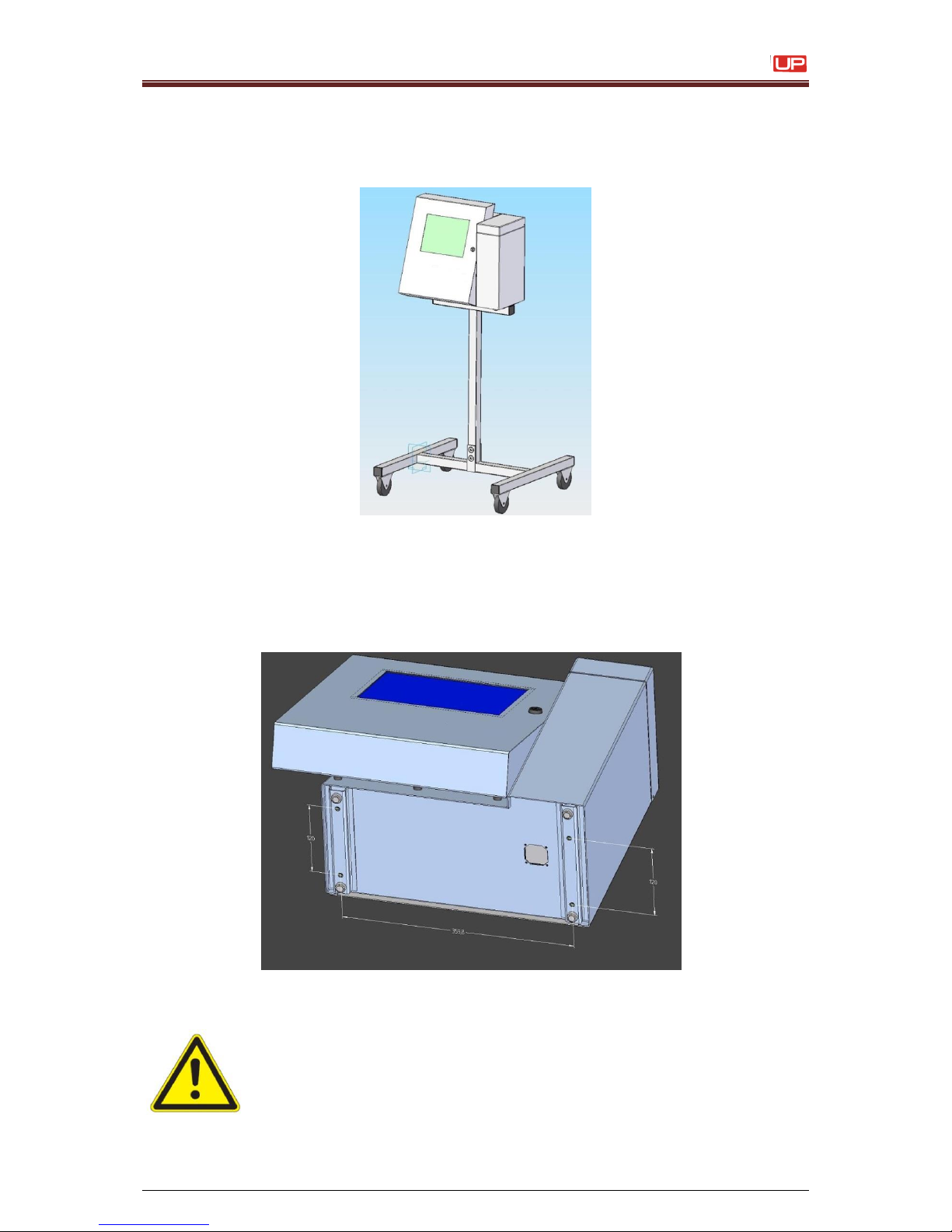
Figure 4
For this it is expedient to place the device on a device support.
The device has four fastening possibilities for secure setting up and should be screw
connected at the place of setting up.
Figure 5
Fastening options
A place of setting up with sufficient load bearing capacity and stability must
be chosen. Prior to assembly the place of setting up must be cleaned of
dirt and contamination (residue of lubricants etc.).
Movable underframe
for JET3up:
Page 24
Service Manual JET3
24 Rev. 1.0
5.3 Installation
For adaption to the production line several works have to be carried out and operating
parameters have to be set before start of operation.
5.3.1 Mains supply
Mains supply!
The device does not have a mains switch and should be only
connected to an easy accessible socket close to the installation
location!
The up should be connected to AC voltage 100 - 240 V AC, 50 – 60 Hz with an
appropriate plug. The socket should be provided with a clear designation
(e.g.: JET3up).
After connecting to the mains power supply the initialization of the device will be carried
out automatically. After this process the JET3up is ready for operation.
You will find further information regarding the initialization in the chapter
Initialization of device!
5.3.2 Grounding (Potential equalization)
Grounding (Potential equalization)!
In case of a non existing grounding or that the grounding of the printer
is not carried out properly, this could cause serious injury or death and
it can also cause malfunctions or damages at the printer!
These dangers or demolitions can happen for example because of
electrostatic discharge (ESD) or potential difference.
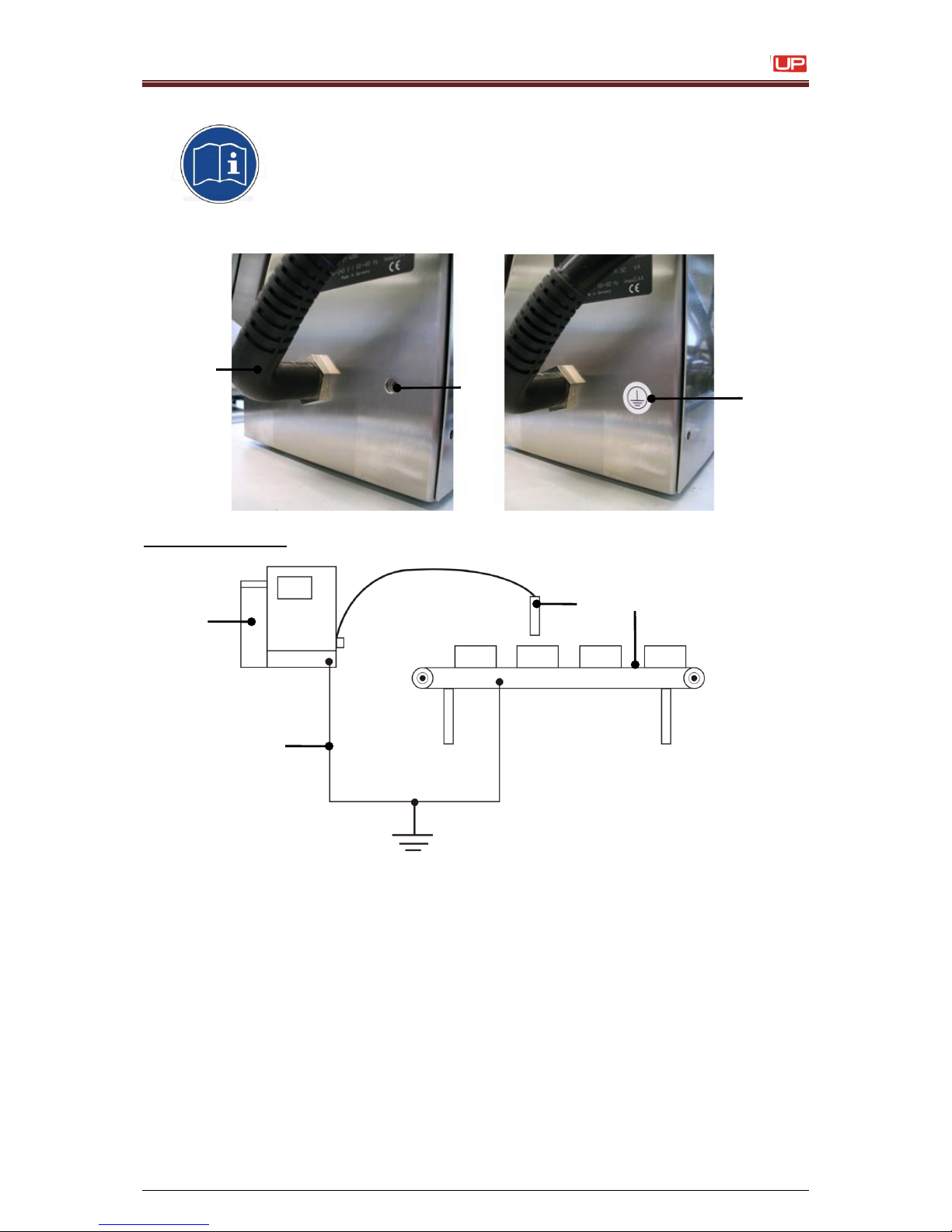
Specially for countries without existing protected earth connection, there is a special
grounding point located at the side of the printer.
This threaded socket must be connected to ground if there is no ground pin in the mains
socket/plug.
The threaded case is sealed inwards and thus IP 65 conform. With a screw and a ring
terminal (cable lug) the grounding can be fixed easily.
Page 25
Service Manual JET3
Rev. 1.0 25
Please note, that the grounding point (6) is hidden behind the round
grounding-symbol-label (7) on the lower left hand side of the cabinet of
the printer.
Figure 6
Grounding scematic
Grounding scematic and gounding point
1 – Printer cabinet
4 – Grounding line
7 – Grounding symbol-label
2 – Installation (machine)
5 – Umbilical
3 – Print head
6 – Grounding point (M6)
Grounding instructions
A separate grounding line (min. cable cross-section 2,00 mm2) to the printer cabinet
must be installed before the print head is mounted in the installation and before the
printer is plugged to the power supply.
5
7
6
1 3 2
4
Ground/earth
Page 26
Service Manual JET3
26 Rev. 1.0
A separate grounding line (min. cable cross-section 2,00 mm2) to the printer cabinet
must be installed before the print head is mounted in the installation and before the
printer is plugged to the power supply.
The connection must be carried with a solid bonding that corresponds with existing
guidelines.
Annotation: A suitable grounding cable is available optionally (accessories).
The installation (machine) and the printer must have the same potential/ground.
The printer must be always switched off and the mains plug must be
always unplugged if you plug and/or unplug any connectors!
5.3.3 Explosion protection
The device has to be integrated in the lightning protection concept of the operator!
Further more protection measures regarding electrostatics have to be made!
5.3.4 Print head
Inflammable (Risk of fire)!
Combustible gases and liquids cause serious burns. Sources of
ignition must be kept away from the print head!
Risk of injury!
Ink escapes from the head aperture. Spraying of ink into the eyes
can cause blindness. Eye protection is necessary!
Page 27
Service Manual JET3
Rev. 1.0 27
The print head should be mounted to the printed product that the notch in the head cover
is placed vertical to the moving direction of the product. It can be installed horizontal,
vertical, from the top or from the bottom.
For installation from the bottom it has to be prevented that dirt can enter in the print
head. For this a head ventilation is required which can be purchased optionally.
The print head mounting should be carried out that a fast separation of the print head
from the device for cleaning purposes is possible.
The print head should be attached vibration-free. The hose connection
of the print head should not be smaller as a radius of R60 statistically
and dynamically not below R100!
The distance of the print head to the product depends on the required character height.
As smaller the required character height, as smaller the distance of the print head to the
product (smaller distances produce better type quality)
Note: In general a distance of round about 8-10mm is recommended.
For applications with extreme small or large character heights a micro- and macro print
head are available optionally.
Installation of print head
During an installation of a device in a production line, the operating
staff should be not endangered. Due to moving products under the
print head danger of bruisings and shearing can be caused. The
regulations of the machinery directives should be observed!
Page 28

28
Service Manual JET3
6 Trouble shooting
6.1 Trouble shooting
Problem
Reason
Solution
Remarks
Ink build-up on the gutter
Print height is too small
Wrong position of the ink stream in the
gutter
Viscosity is too thin
HV module on controller board is defective
Increase print height in job parameter.
Adjust print head.
Leave printer on with open nozzle and
check until viscosity matches with
nominal visco setting
Exchange power supply.
See service document “print head
adjustment”.
Ink stream is jumping
Dirt inside the nozzle
The position of the ink stream inside the
charging electrode or gutter is not correct.
Incorrect hydraulic pressure setting
Viscosity does not match with default value
Oscillator defect
Clean nozzle
Clean print head
Exchange oscillator
See service document “cleaning of
nozzle”.
See service document “head
adjustment”.
Check viscosity with nominal setting.
Exchange oscillator => see service
document “exchange oscillator”.
Ink build-up on the deflection
plates
Head filter clogged
The position of the ink stream in the gutter
tube is not correct
Service is due
Hydraulic pressure too low"
Exchange head filter
Adjust print head
Check nominal hydraulic settings for
nozzle type.
Page 29

29
Ink is dropping from print head
Suction does not work
Reducer in the ECOSOLVE is blocked
Ecosolve blocked
The position of the ink stream in the gutter
Wrong ink stream position inside the
charging electrode
Dirt inside the nozzle
Adjust print head
Clean nozzle
Check and clean reducer in ECOSOLVE.
See service document “cleaning of
nozzle”.
See service document “head
adjustment”.
When opening the nozzle, the
gutter is glued with ink.
Nozzle O-ring damaged
Gutter not aligned
Gutter or O-ring dirty
Exchange nozzle O-ring
Check and adjust print head.
Clean print head with solvent.
See the service document “cleaning
nozzle”.
See the service document “head
adjustment”.
See service document “cleaning of print
head”.
Printer is not printing
Incorrect job parameters
Encoder does not work
Product sensor does not work
No high voltage
Character height is adjusted too small
Could not switch on printer
Mains plug not plugged in
No voltage to mains socket
Touch screen broken
Connection cable of touch screen loose
Defective power supply
Defective controller
No function of touch display
Touch screen broken
Flat cable of touch screen controller loose
Check cable connection and if necessary
change the touch display
See the service documentation
“exchange touch display”
Head cover is not detected
Head cover contact has loosen cable
connection inside the head flange
Broken cable inside the umbilical
Open head cover contact and check
cable connections
Page 30

30
Service Manual JET3
Ink build-up on the head cover.
Print head distance to close to the product
Stroke distance too low
Electrostatic charge on the product
Too high setting of “contrast-function”
Product counter is
incrementing, but no print out
Wrong print go delay
No high voltage onto deflection plates
Character height too low or set to 0%
Slot of head cover blocked by dirt
Low contrast on the print out
Wrong viscosity (too thin)
(pigmented inks) the stirring device
(agitator) does not work
Pigmented ink not shaken long enough
Font width is too large
Bad print quality
Oscillator defective
Dirt inside the nozzle
Production speed is too high or wrong
“speed mode” is selected
Wrong viscosity
Lower part of print out is
missing.
Too little character height
Ink stream position is adjusted too far to
the left side of the gutter
Hydraulic pressure too high
Upper part of print out is
missing
Wrong viscosity
Print head is dirty
Incorrect hydraulic pressure
Drops hang on the deflection plate
Deflection plate is defective
Print out is squeezed together
(in the height)
Wrong viscosity
Oscillator is defective
Dirt inside the nozzle
Defective HV module
Deflection plate is defective
Page 31

31
Error and Warning List
Code - Nr
Error text
Reason
Solution
Remarks
2
2=Internal communication
error
Internal communication problem:
A CPU (RIP) has sent a message (identifier)
to a different CPU which is unknown.
Possibly, firmware, and software versions
are not compatible.
Carry out a software update
If software update is without
success, please contact
LEIBINGER
3
3=Internal communication
error.
Too much data.
Internal communication problem.
Internal message at the receiver was too
large (currently 1MB)
Carry out a software update
Check files on maximum size of 1
MB. fonts, graphics, or job
If no success, please contact
LEIBINGER
4
4=Internal communication
error
Internal communication problem.
Single data packet doesn't fit in the length
(= transmission errors)
Read the script and interface
protocol documentation!
If no success, please contact
LEIBINGER
5
5=Internal communication
error
Internal communication problem.
Block transfer error (= transmission errors)
Reboot again the system.
If no success, please contact
LEIBINGER
6
6=Internal communication
error.
Too much data.
Get to large amount of data.
Reboot again the system.
If no success, please contact
LEIBINGER
7
7=Internal communication
error
Internal communication problem:
A CPU (RIP) has sent a message (identifier)
to a different CPU which is unknown.
Reboot again the system.
Carry out a software update.
Change the controller board.
See the service document
"Exchange the Controller board
JET3up"
If no success, please contact
LEIBINGER
Page 32

32
Service Manual JET3
20-24
20=Internal interface error
Internal communication problem:
A CPU (RIP) has sent a message (identifier)
to a different CPU which is unknown.
Reboot again the system.
Carry out a software update.
Change the controller board.
See the service document
"Exchange the Controller board
JET3up"
If no success, please contact
LEIBINGER
100-104
100=Internal communication
error
Internal communication problem:
A CPU (RIP) has sent a message (identifier)
to a different CPU which is unknown.
Reboot again the system.
Carry out a software update.
Change the controller board.
See the service document
"Exchange the Controller board
JET3up"
If no success, please contact
LEIBINGER
105
105=Internal communication
error.
Too much data.
Internal communication problem.
Internal message at the receiver was too
large (currently 1MB)
Check files on maximum size of 1
MB. fonts, graphics, or job
109/110
109=Internal communication
error
Internal communication problem:
A CPU (RIP) has sent a message (identifier)
to a different CPU which is unknown.
Reboot again the system.
Carry out a software update.
Change the controller board.
See the service document
"Exchange the Controller board
JET3up"
If no success, please contact
LEIBINGER
Page 33

33
111
111=Internal communication
error
Internal communication problem.
A CPU has sent a message, but get no
response from the recipient or the message.
Typical error when a CPU crashes, hangs,
or has been reset. If there no principled
software error and this error occurs more
often might this an indication of a hardware
failure. Cyclone Board defective (unlikely),
5V power supply is unstable or very brief
network drop outs (more likely). Currently
the printer GUI is resetting the system if
such an error appears, to try to get the
system working again.
112
112=Internal communication
error
Internal communication problem.
A CPU has sent a message, but get no
response from the recipient or the message.
Typical error when a CPU crashes, hangs,
or has been reset. If there no principled
software error and this error occurs more
often might this an indication of a hardware
failure. Cyclone Board defective (unlikely),
5V power supply is unstable or very brief
network drop outs (more likely). Currently
the printer GUI is resetting the system if
such an error appears, to try to get the
system working again.
113
113=Internal communication
error
Internal communication problem:
A CPU (RIP) has sent a message (identifier)
to a different CPU which is unknown.
Reboot again the system.
Carry out a software update.
Change the controller-board.
See the service document
"Exchange the Controller board
JET3up"
If no success, please contact
LEIBINGER
Page 34

34
Service Manual JET3
114
114=Internal communication
error
Internal communication problem:
The lenght of a single packet doesn't fit in
the length.
Read the script and interface
protocol documentation!
If no success, please contact
LEIBINGER
115-124
115=Internal communication
error
Internal communication problem:
A CPU (RIP) has sent a message (identifier)
to a different CPU which is unknown.
Reboot again the system.
Carry out a software update.
Change the controller-board.
See the service document
"Exchange the Controller board
JET3up"
If no success, please contact
LEIBINGER
1000
1000=Joblist could not be
loaded
The RIP was unable to load the job list
(faulty job list!) Possible caused by
manually-created job list.
Check the job-list and job
parameter again.
1001
1001=Script begin job
syntax error
Syntax error in beginning of job script
Read the script and interface
protocol documentation!
1002
1002=Jobparameter syntax
error
Syntax error in job parameters.
Read the script and interface
protocol documentation!
1003
1003=Counter variable
syntax error
Syntax error in counter variable.
Read the script and interface
protocol documentation!
1004
1004=Barcodeobject syntax
error
Syntax error in the bar code object.
Read the script and interface
protocol documentation!
1005
1005=Textobject syntax
error
Syntax error in the text object.
Read the script and interface
protocol documentation!
1006
1006=Replacement syntax
error
Syntax error in substitution variable.
Read the script and interface
protocol documentation!
1007
1007=Timevariable syntax
error
Syntax error in date time variable.
Read the script and interface
protocol documentation!
1008
1008=Shiftvariable syntax
error
Syntax error in shift code variable.
Read the script and interface
protocol documentation!
Page 35

35
1009
1009=Extern text object
syntax error
Syntax error in the external text object.
Read the script and interface
protocol documentation!
1010
1010=Too much objects
More than 32 objects in a job.
Read the script and interface
protocol documentation!
1011
1011=Font missing
The font could not be loaded in the job.
Mostly caused by copying a job without
copying the required fonts.
Copy the required font into
internal memory and push
function reload all fonts.
1012
1012=Illegal character in
barcodeobject
Not allowed characters in the bar code
object.
Read the script and interface
protocol documentation!
1013
1013=Uncorrect length of
barcodeobject
Too many characters in the bar code object.
Read the script and interface
protocol documentation!
1014
1014=Mailing data too long
Mailing data too large. A mailing object is in
the job. The mail data is however too long or
there are too many wildcards in the job.
Read the script and interface
protocol documentation!
1015
1015=Mailing buffer full
Mailing buffer is full. Too many data have
been sent.
Read the script and interface
protocol documentation!
1017
1017=Counter syntax error
Syntax error in the counter object.
Read the script and interface
protocol documentation!
1018
1018=Database index
number invalid or missing
Database index number is not allowed or is
missing.
Read the script and interface
protocol documentation!
1019
1019=Database index
number isn't consecutively
numbered
Database index numbers are not sequential
Read the script and interface
protocol documentation!
Page 36

36
Service Manual JET3
1021
1021=Extern Text: Double
print happened
External text: double print has occurred.
There were no new data sent.
Check the data handling of the
communication computer.
Check data cable and
connections.
1200
1200=Memory error in
SRAM
SRAM memory on the Cyclone Board
seems defective.
Change the controller board.
See the service document
"Exchange the Controller board
JET3up"
1201
1201=Check sum error.
Please check battery
voltage.
Checksum error when testing the battery
buffered SRAM memory.
Cause
1. After initial operation or after battery
replacement when mains has been
unplugged.
2. Battery is empty
3. Memory content is incorrect
Exchange the battery on the
controller board!
1202
1202=Memory access error
in SRAM
Software error!
Carry out a software update.
If software update is without
success, please contact
LEIBINGER
1203
1203=Low battery voltage.
Please remove battery
Battery voltage is under the limit.
So as not lose memory contents you should
exchange the battery when mains plugged,
but switched off (note! only trained staff)
Exchange the battery onto the
controller board!
Page 37

37
1210
1210=PrintGo error
"PrintGo error."
Another print go signal was detected while
the system is printing.
- Several print go from same product
- distance between sensor and print head is
too big
1. Adjust the print go sensor that
one product is sending only one
signal.
2. Reduce the distance from
sensor to print head.
3. Use print go hold function
See 0perating manual JET3up
Figure 8.5.1.4 / Page
196ReleaseR1.06
1211
1211=Internal
communication error
Softwareupdate!
Carry out a software update.
1212
1212=Internal
communication error
Internal communication problem:
A CPU (RIP) has sent a message (identifier)
to a different CPU which is unknown.
Reboot again the system.
Carry out a software update.
Change the controller board.
See the service document
"Exchange the Controller board
JET3up"
If no success, please contact
LEIBINGER
1213
1213=Job data too large
A job is bigger than 1 MByte.
Check the size of the print job and
reduce if necessary.
Read the script and interface
protocol documentation!
1214
1214=Too much strokes in
one job
more as 20000 strokes are used within the
job
Read the script and interface
protocol documentation!
1215
1215=Empty joblist
Empty job list.
Read the script and interface
protocol documentation!
1216
1216=Faulty RIP memory
reservation
Error in RIP memory reservation.
Read the script and interface
protocol documentation!
Page 38

38
Service Manual JET3
1217
1217=Extern text too large
External text is too long for the external text
object or false.
(Unauthorized characters?)
Read the script and interface
protocol documentation!
1218
1218=X3 Outputdriver
overloaded.
Outputs disabled
The output drivers for the X 3 outputs logs
too hot (overload, short-circuit)
Note: in order to protect IC, all outputs are
switched off automatically.
Power in X 3 output driver too high. The
outputs were locked for safety.
Rebooting the system will activate
the outputs again.
Check if there is a short circuit
onto X3 input.
1219
1219=Power input
overloaded.
Please check your power
supply net immediately
The input voltage is too high.
Check the power supply net for
over voltage.
1220
1220=Object counter
reached end value. Print
has stopped.
An object counter has reached its defined
end.
See 0perating manual JET3up
Figure 8.7.3 Counter / Page218
ReleaseR1.06
1221
1221=Job list reached end.
Print has stopped.
A job list (batch or job organisator) has
reached the end and will not be repeated.
See operating manual JET3up
Figure / Page ReleaseR1.06
1222
1222=Job not loaded or
faulty
Job was not loaded or is corrupt.
Check the job settings in job
editor and save it again.
If jobs has been imported by USB
device, check if files are not
corrupt.
1223
1223=Last Database record
printed.
Print has stopped.
Last database entry printed. Printing has
been stopped.
The database has reached the
end and printer stopped to print.
Page 39

39
1224
1224=Stop count value
reached.
Print has stopped.
End of counter reached. Printing has been
stopped.
1300
1300=Faulty viscomeasurement.
Please check visco pump
and viscometer.
The ball has not reached the upper sensor in
the viscometer
= Sensor broken, ball hangs down, any air in
the viscometer.
Start constant bleed function for
about 10 minutes to get the air
out of the system.
Take out the viscometer and flush
it several times with solvent.
If no success exchange the
viscometer.
1301
1301=Faulty viscomeasurement.
Please check visco pump
and viscometer.
The ball does not fall (top stuck)
Dirt in the Glassss tube.
Take out the viscometer and flush
it several times with solvent.
If no success exchange the
viscometer.
1302
1302=Faulty viscomeasurement.
Please check visco pump
and viscometer.
The ball has not left the upper sensor
Dirt in the Glassss tube
Take out the viscometer and flush
it several times with solvent.
If no success exchange the
viscometer.
Page 40

40
Service Manual JET3
1303
1303=Faulty viscomeasurement.
Please check visco pump
and viscometer.
The maximum fall time of 16.4 seconds was
exceeded
i.e. the ball has passed the upper sensor,
but it has not arrived at the lower sensor.
1 Ink is extremely thick
2. Lower sensor defective (no signal
delivers)
3. Ball is stuck on the way down
Take out the viscometer and flush
it several times with solvent.
If no success exchange the
viscometer.
1304
1304=Faulty viscomeasurement.
Please check visco pump
and viscometer.
The minimum event time of 500ms has been
exceeded.
1 Lower sensor defective (provides
continuous signal)
2. Air in the tube?
1305
1305=Attention, ink too
thick!
Fall time of the ink is 2 seconds higher than
the nominal fall time (= ink to thick)
Note!
This error message is issued only once after
switching on.
After confirmation of the error this is not
repeated.
Page 41

41
1306
1306=Attention, ink too thin!
Fall time of the ink is less than 2 seconds
lower than the nominal fall time
(= ink too thin)
1307
1307=The ink flow pressure
is faulty. Hydraulic control
has stopped. Please check
the pump and all
connections.
The main pump could not push up the
membrane in the middle position in normal
operation within 2.5 seconds.
Possible causes:
1 Air in the system (probably the most
common cause)
2. Leakage
3. Bleed valve does not work correctly
(possibly damaged)
4. Main pump do not run (pump is defective)
5. Sensor wiring to the pressure tank failed
(continuous)
6. Hall sensor for membrane location defect
7. Diaphragm faulty (leaky) or hangs
"Note: when this error occurs, the entire
hydraulic system for security reasons is
switched off (emergency stop)"
Page 42

42
Service Manual JET3
1308
1308=Pressure fault.
Hydraulic control has
stopped. Please check air
pump and all connections.
The compressor could not build up the
pressure within 120 seconds (!)
1 Pneumatic part leaking
2. Defective compressor
(possibly even wiring!)
3. Air filter clogged"
1309
1309=Ink Flow sensor error.
Hydraulic control has
stopped.
Ink flow sensor reports out of ink
Possible causes:
1 Inkjet does not apply in the gutter tube
2. Even no ink-jet available
(Nozzle blocked, ink valve is not working)
3. Cable break or ink flow sensor contact
problem
4. Return flow sensor or wiring "flooded" with
ink.
Adjust ink stream
Clean nozzle
1310
1310=Ink tank reached low
level position. Please refill
ink.
Please refill ink.
1311
1311=Solvent tank reached
low level position. Please
refill solvent.
Please refill solvent.
Page 43

43
1312
1312=Leakage found in the
hydraulic area. Hydraulic
control has stopped. Please
check hydraulic
immediately.
Leakage sensor is giving alarm!
1 Hydraulic leakage
2. Any water on the bottom"
Check the hydraulic part if there is
any ink or solvent leak. If no leak
could be detected, clean leak
sensor with solvent and activate
hydraulic control again. If humidity
is found onto the leak sensor, dry
it and activate the hydraulic
control again.
1313
1313=Invalid Hydraulic
Settings
Invalid hydraulic setting
(Pressure much too high, visco correction
factor much to low or much too big.)
1315
1315=Inktyp not supported
Ink type is not supported in the printer.
Carry out a software update
If software update is without
success, please contact
LEIBINGER
5000
5000=Charge Electrode
dirty.
Please check if charge
electrode is dirty and clean if
necessary.
"Causes:"
1. Electrode block dirty with ink
2. Head Electronics "filled with ink or solvent
", system leak
3. HV discharge onto head electronics
4. Error when reassembling deflection unit
head chassis (HV Cable crushed, seal
damaged).
Clean print head
Page 44

44
Service Manual JET3
5001
5001=Phasing error.
Please check if charge
electrode is dirty and clean if
necessary.
"Causes:"
1. Electrode block dirty with ink
2. Head Electronics "filled with ink or solvent
", system leak
3. HV discharge onto head electronics
4. Error when reassembling deflection unit
head chassis
(HV Cable crushed, seal damaged).
Clean print head
Adjust ink stream
Exchange Electrode block
Exchange umbilical
5002
5002=No charge electrode
response.
Please check if charge
electrode is dirty and clean if
necessary.
No detector responses when attempting the
drop break point.
Causes:
1 Wrong frequency setting
2. See 5000
3. Oscillating or wiring to the oscillator
defective.
Flooded oscillator (due to improper
installation)
4. Oscillator voltage circuit overload
(no compensation set with 10 m cable, etc.)
5. Electrode block defective.
Exchange oscillator
Exchange electrode block
5003
5003=Drop-break-off point
couldn't be adjusted
correctly.
Drop break point setting bad or not possible
i.e. drops could be detected, but a drop
break point could not be adjusted.
Causes see „error 5002“
Exchange oscillator
Exchange electrode block
Page 45

45
5004
5004=Phasing error.
The time interval between
two PrintGo`s is too small.
Phasingerror.
The time interval between two PrintGo`s is
too small.
Increase delay or reduce production speed.
5010-5014
5010=An error occurred
while the function Nozzle
Open / Nozzle Close was in
process. Check the
mechanics for guttermovement.
No Encoder signals when attempting to drive
the motor.
Causes:
1. Motor is jammed
2. Encoder or encoder wiring defective
3. Motor or a faulty motor driver (motor does
not run)
4. Plug of the motor lose or filled with ink.
Clean the print head with solvent.
Change the nozzle motor.
Change controller board.
See the service document cleaning
print head of JET3up.
See the service document
Exchange controller board.
5015
5015=Motor direction
incorrect
Motor direction is wrong, i.e. the counting
direction of the encoder does not match the
desired direction of movement.
Change the nozzle motor.
Check if the connector of nozzle
motor is loose.
5016
5016=Nozzle was open
already during Power On
process.
Nozzle was open during the power-on
process.
It is only an info message to
remind you that the printer has
been switched off with an open
nozzle. Possible that mains went
off or mains plug has been
removed while the nozzle has
been open.
Page 46

46
Service Manual JET3
5020
5020=HV-Current too high.
Check deflection plate for
dirt or humidity.
Causes:
1. Dirty deflection plates
2. Head with ink or solvent filled
3. Error of the assembly
(usually squeezed HV cable)
Clean the print head
5030
5030=Error.
A StrokeGo occured while a
stroke was in progress. So
strokes will be lost.
Error. A StrokeGo occured while a stroke
was in progress. So strokes will be lost
because of too high production speed.
Reduce the production speed if
possible.
Increase the stroke distance if
possible.
Use a different speed mode to get
a higher possible production
speed.
Use a smaller font in the print job
to reduce the maximum size of
drops in the height.
Page 47

47
5031
5031=The printing speed
much too highly. Drops will
be lost.
Occurs when the print is (permanently) too
fast, the StrokeGo monitoring is disabled
and as a result, the DAC FIFO run over.
Printing is too fast.
Reduce the production speed if
possible.
Increase the stroke distance if
possible.
Use a different speed mode to get
a higher possible production
speed.
Use a smaller font in the print job
to reduce the maximum size of
drops in the height.
5042
5042=Drop calculation too
slow
Occurs when the print speed is permanently
too fast.
Reduce the production speed if
possible.
Increase the stroke distance if
possible.
Use a different speed mode to get
a higher possible production
speed.
Use a smaller font in the print job
to reduce the maximum size of
drops in the height.
Increase the distance between
the different prints.
5043
5043=Mailing buffer empty
Mailing buffer empty.
During a print another print go appears and
causes that the buffer is getting empty.
Check the print go sensor for
double trigger and if possible
adjust the sensitivity.
Use „hold of distance“ to ignore
double trigger.
See 0perating manual JET3up
Figure 8.5.1.4 / Page
196ReleaseR1.06
Page 48

48
Service Manual JET3
5050
5050=PrintGo distance is
shorter than Print length
The print distance specified in the JobEditor
between two print is shorter than the print
itself (i.e. the next print drops into first one).
Workaround: increase the PrintGo distance
Increase the PrintGo distance or
reduce stroke distance of the print
job.
5051
5051=Error.
A PrintGo occured while a
print was in progress. So
prints will be lost.
During an ongoing print, the next PrintGo
signal has been already received i.e. the
print out is longer than the distance between
two Print Go.
1. Adjust the print go sensor that
one product is sending only one
signal.
2. Reduce the distance from
sensor to print head.
3. Use print go hold function
See 0perating manual JET3up
Figure 8.5.1.4 / Page
196ReleaseR1.06
5060
5060=Charge voltage
overload.
"An overload situation of the charging
voltage amplifier (current)
Possible causes:
1. Short circuit on charge voltage line
(possibly head)
2. Coaxial cable or chassis under deflection
unit "flooded"
(check coaxial cable impedance, ohmic
resistances typical error <1MOhm
Clean print head
Exchange umbilical
Adjust ink stream
Exchange Electrode block
Check coaxial cable impedance,
ohmic resistances typical error
<1MOhm
See service document
“cleaning of print head”
See service document
“adjust print head”.
See service document
„change the electrode block“.
5061
5061=Piezo voltage
overload.
Power in the oscillating power amplifier too
high.
1. Short-circuit in oscillator voltage power
line
2. Defective oscillator
Clean print head
Adjust ink stream
Exchange oscillator.
Exchange umbilical
See service document
“cleaning of print head”.
See service document
“adjust print head”.
See service document
„exchange oscillator“.
Page 49

49
10006
10006=Font Error.
One or more Fonts are
incorrect.
A font in the FONT directory is empty,
corrupted or cannot be read from the disk.
Carry out a software update
If software update is without
success, please contact
LEIBINGER
10007
10007=Jobfile Error
The desired job in the JOB directory is
empty, corrupted or cannot
be read from the disk.
Create a new job and load to
print.
10009
10009=Too many Fonts.
Please remove one or more
Fonts.
Too many Fonts. Please remove one or
more Fonts.
Please remove one or more
Fonts.
10201
10201=Service required
(working hours)
Service required (working hours)
A service for the printer is due.
10202
10202=Service required
(time interval)
Service required (time interval)
A service for the printer is due.
11000
11000=Warning!
You have opened the head
cover.
The head cover has been opened during the
production.
Before removing the head cover,
push button print stop if printer is
busy.
11015
11015=RIP- or SDCSoftware not found
Start again the software update.
Carry out a software update
If software update is without
success, please contact
LEIBINGER
Page 50

50
Service Manual JET3
11020
11020=Nozzle has not been
closed
1. Print head mechanism stuck with ink.
2. Motor defective
3. Motor connector loose
Clean the print head with solvent..
Check if the connector of nozzle
motor is loose.
Change the nozzle motor
See the service document “cleaning
print head of JET3up”.
11025
11025=Nozzle could not be
opened
1. Print head mechanism stuck with ink.
2. Motor defective
3. Motor connector loose
Clean the print head with solvent.
Check if the connector of nozzle
motor is loose.
Change the nozzle motor.
See the service document “cleaning
print head of JET3up”.
11030
11030=No phasing
The time distance between the individual
print outs is too short
Increase the print go delay to get
more time between two prints.
Reduce the production speed if
possible.
11035
11035=Job could not be
loaded
Job could not be loaded.
The print job is physically
damaged or does not exist.
11040
11040=Printstart not
possible
Start print not possible.
1. Printer is not ready for printing.
2. Head cover is open
3. Nozzle is closed
Check if head-cover is on.
Check if nozzle is closed or open.
If closed, push button "nozzle
open"
11045
11045=Nozzle was open
already during Power On
process.
Nozzle was open during the power-on
process.
It is only an info message to
remind you that the printer has
been switched off with an open
nozzle. Possible that mains went
off or mains plug has been
removed while the nozzle has
been open.
Page 51

51
11050
11050=Error in Database
source.
Print was stopped !
Errors in the database source.
Printing has been stopped.
Read the script and interface
protocol documentation!
12000
12000=Invalid packet
received
Sent wrong parameters per interface.
Read the script and interface
protocol documentation!
12020
12020=Current job not
found
Requested file not found.
Read the script and interface
protocol documentation!
12025
12025=Requested file not
found
Requested file not found.
Read the script and interface
protocol documentation!
12045
12045=Receiving current
job from script failed
Failure in script for the currently received
job.
Read the script and interface
protocol documentation!
12050
12050=Receiving current
job error
Failure in script for the currently received
job.
Read the script and interface
protocol documentation!
12100
12100=Nozzle could not be
opened!
Please check Nozzle in
Printhead ServiceFunctions.
1. Print head mechanism stuck with ink.
2. Motor defective
3. Motor connector loose
Clean the print head with solvent.
Check if the connector of nozzle
motor is loose.
Change the nozzle motor.
See the service document “cleaning
printhead of JET3up”.
Page 52

52
Service Manual JET3
12105
12105=Nozzle could not be
closed!
Please check Nozzle in
Printhead ServiceFunctions.
1. Print head mechanism stuck with ink.
2. Motor defective
3. Motor connector loose
Clean the print head with solvent.
Check if the connector of nozzle
motor is loose.
Change the nozzle motor.
See the service document “cleaning
printhead of JET3up”.
12107
12107=Please activate new
Ink!
According to consumption
measurement more Ink was
used than activated. Please
activate with new bottle
(TAG) and fill tank if
necessary.
Please activate new Ink!
According to consumption measurement
more Ink was used than activated. Please
activate with new bottle (TAG) and fill tank if
necessary.
12108
12108=Please activate new
Ink!
According to consumption
measurement more Ink was
used than activated. Please
activate with new
bottle(TAG) and fill tank if
necessary. Otherwise,
machine will locked
automatically !
Please activate new Ink! According to
consumption measurement more Ink was
used than activated. Please activate with
new bottle (TAG) and fill tank if necessary.
Otherwise, machine will locked
automatically!
Page 53

53
12109
12109=Please activate new
Solvent! According to
consumption measurement
more Solvent was used than
activated. Please activate
with new bottle (TAG) and
fill tank if necessary.
Otherwise, machine will
locked automatically !
Please activate new Solvent!
According to consumption measurement
more Solvent was used than activated.
Please activate with new bottle (TAG) and fill
tank if necessary. Otherwise, machine will
locked automatically!
12110
12110=Please activate new
Solvent! According to
consumption measurement
more Solvent was used than
activated. Please activate
with new bottle (TAG) and
fill tank if necessary.
Please activate new Solvent!
According to consumption measurement
more Solvent was used than activated.
Please activate with new bottle (TAG) and fill
tank if necessary.
12111
12111=Ink Jet is locked!
Please activate new Ink.
According to consumption
measurement more Ink was
used than activated. Please
activate with new bottle
(TAG) and fill tank if
necessary.
Ink Jet is locked!
Please activate new Ink. According to
consumption measurement more Ink was
used than activated. Please activate with
new bottle (TAG) and fill tank if necessary.
Page 54

54
Service Manual JET3
12112
12112=Ink Jet is locked!
Please activate new
Solvent. According to
consumption measurement
more Solvent was used than
activated. Please activate
with new bottle (TAG) and
fill tank if necessary.
Ink Jet is locked!
Please activate new Solvent. According to
consumption measurement more Solvent
was used than activated. Please activate
with new bottle (TAG) and fill tank if
necessary.
12113
12113=Ink refilled without
activation.
Please activate now by
holding the bottle to the
TAG-Reader.
Ink refilled without activation.
Please activate now by holding the bottle to
the TAG-Reader.
12114
12114=Solvent refilled
without activation. Please
activate now by holding the
bottle to the TAG-Reader.
Solvent refilled without activation.
Please activate now by holding the bottle to
the TAG-Reader.
12116
12116=Less than 1MB of
free disk space available.
Please remove unnecessary
files to get more free disk
space.
Less than 1MB of free disk space available.
Please remove unnecessary files to get
more free disk space.
Please remove unnecessary files
(jobs, fonts or graphics) to get
more available disk space.
Page 55

55
21310
21310=Ink tank reached low
level position. Please hold
new bottle to the TAG
Reader and activate it. After
this fill in the complete bottle
immediately into the ink
tank.
Ink tank reached low level position.
Please hold new bottle to the TAG Reader
and activate it. After this fill in the complete
bottle immediately into the ink tank.
21311
21311=Solvent tank
reached low level position.
Please hold new bottle to
the TAG Reader and
activate it. After this fill in the
complete bottle immediately
into the solvent tank.
Solvent tank reached low level position.
Please hold new bottle to the TAG Reader
and activate it. After this fill in the complete
bottle immediately into the solvent tank.
Page 56
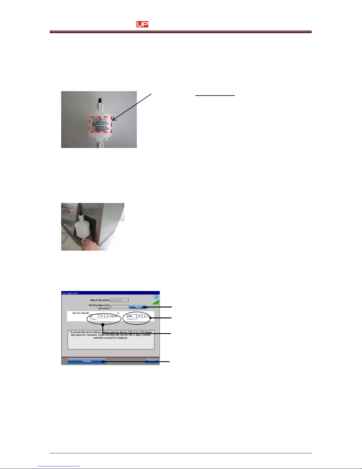
Service Manual JET3
56 Rev. 1.0
7 Service works
7.1 Service TAG
In order to reset the counter for the service interval you must activate a service TAG.
The Tag is located invisible below the label of the main filter.
Important Notice:
The TAG is glued together with the label to the main filter.
Do not try to remove the TAG from the main filter!
This may destroy the TAG!
It is necessary to activate the TAG before you change the main
filter. After the installation, you cannot access the TAG anymore.
Main filter with label
Procedure:
1. Hold the main filter with the label in front of the TAG reader.
The dialog box <TAG Reader Results> pops up.
Open the service interval dialog box with the
TAG
2. Enter the data for the next service interval. The interval is set in months (3) and operating
hours (2). Service will be due after the period or operating hours set, whichever occurs first.
3. Reset the <Working hours since last service> with the button <Reset> (1).
TAG activation
1 – Button <Reset>
2 – Input field <Service Intervall> Hours
3 – Input field <Service Interval> Month
4 – Button <Activate>
4. After setting the desired values confirm with the button <Activate> (4).
3
2
1
4
Page 57
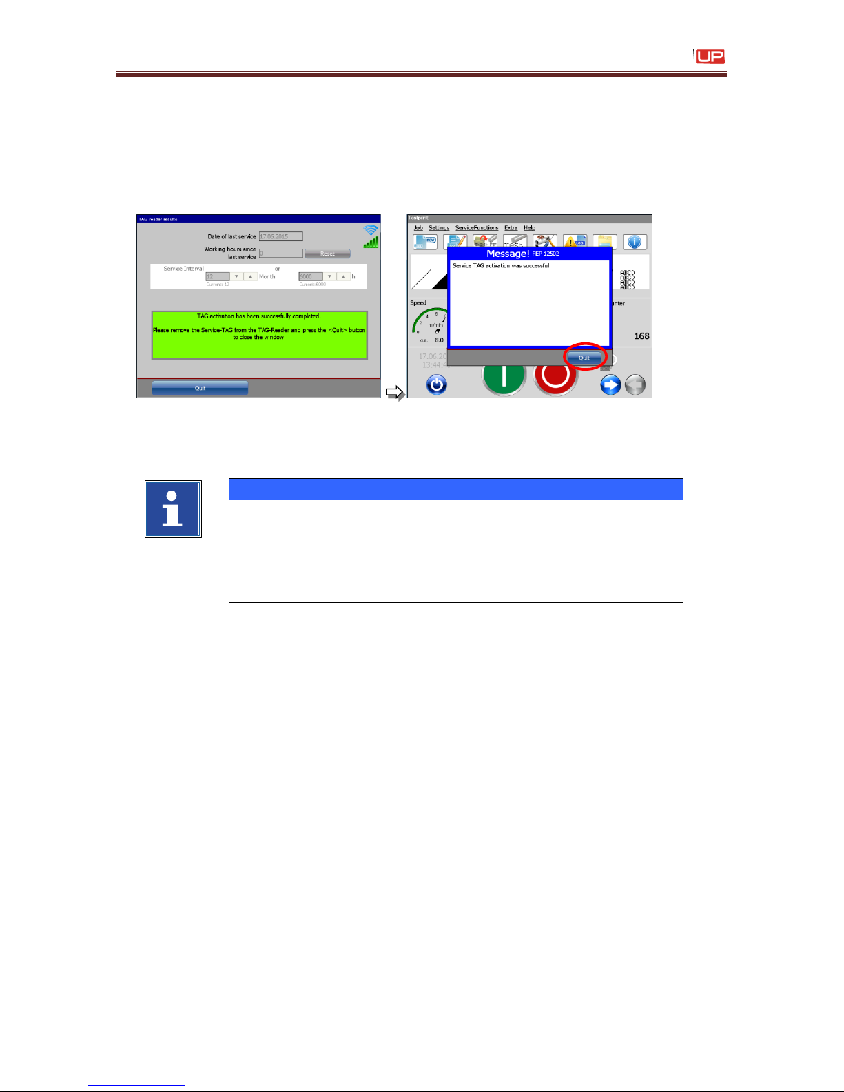
Service Manual JET3
Rev. 1.0 57
5. For a successful activation, it is necessary that you hold the main filter on the TAG reader
during the whole activation process.
Otherwise you will get the error message: “TAG activation failed”.
After a successful activation the new service intervals are saved and the following message
is displayed:
TAG activation
Close the dialog box with the button
<Quit>.
Close the confirmation prompt with the
button <Quit>.
INFORMATION
- For a successful activation you must use a valid TAG.
- You can use a Tag for a successful activation only one time.
- Don`t remove the TAG during the activation process.
Otherwise the TAG could be damaged.
- With an invalid TAG you can open the service interval dialog
box but you can`t save any values.
Page 58
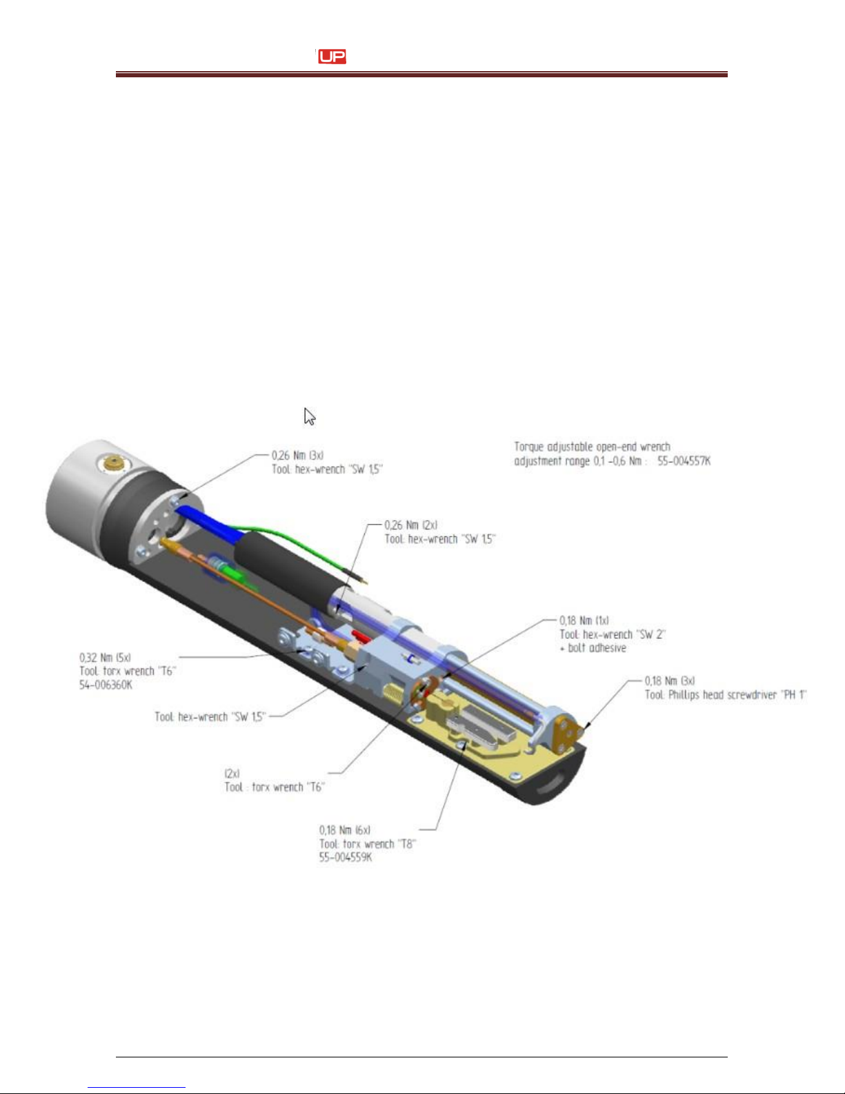
Service Manual JET3
58 Rev. 1.0
7.2 Documentations for
SK4
Torsional moments for SK4
Page 59
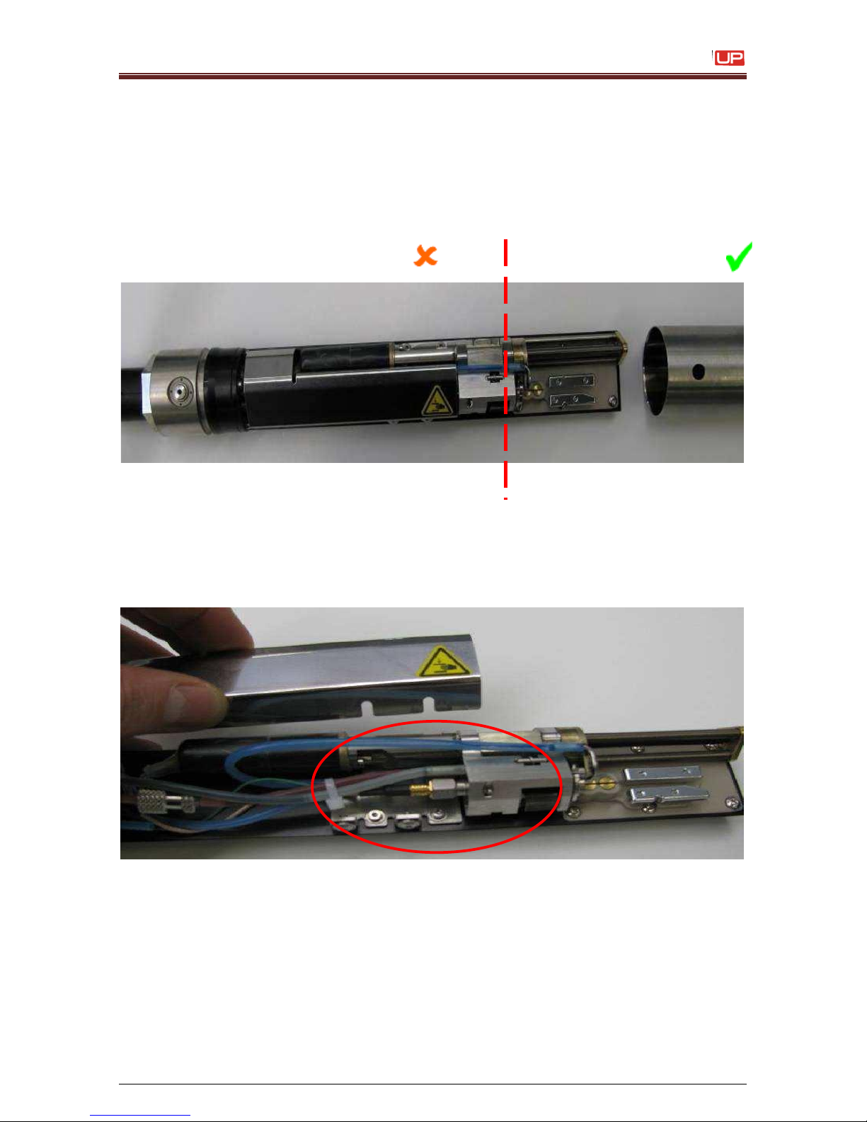
Service Manual JET3
Rev. 1.0 59
1) Cleaning of print head
We want to ask for your attention regarding the print head cleaning process:
Please be aware, that the print head has to be cleaned with solvent only in the front area.
Behind the red line you must not clean with solvent.
Especially the area around the oscillator connection must not be flushed with solvent. Otherwise
solvent could penetrate inside the oscillator or the connector and could cause damages or
mal functions.
no cleaning area => no solvent
cleaning area => solvent
Page 60
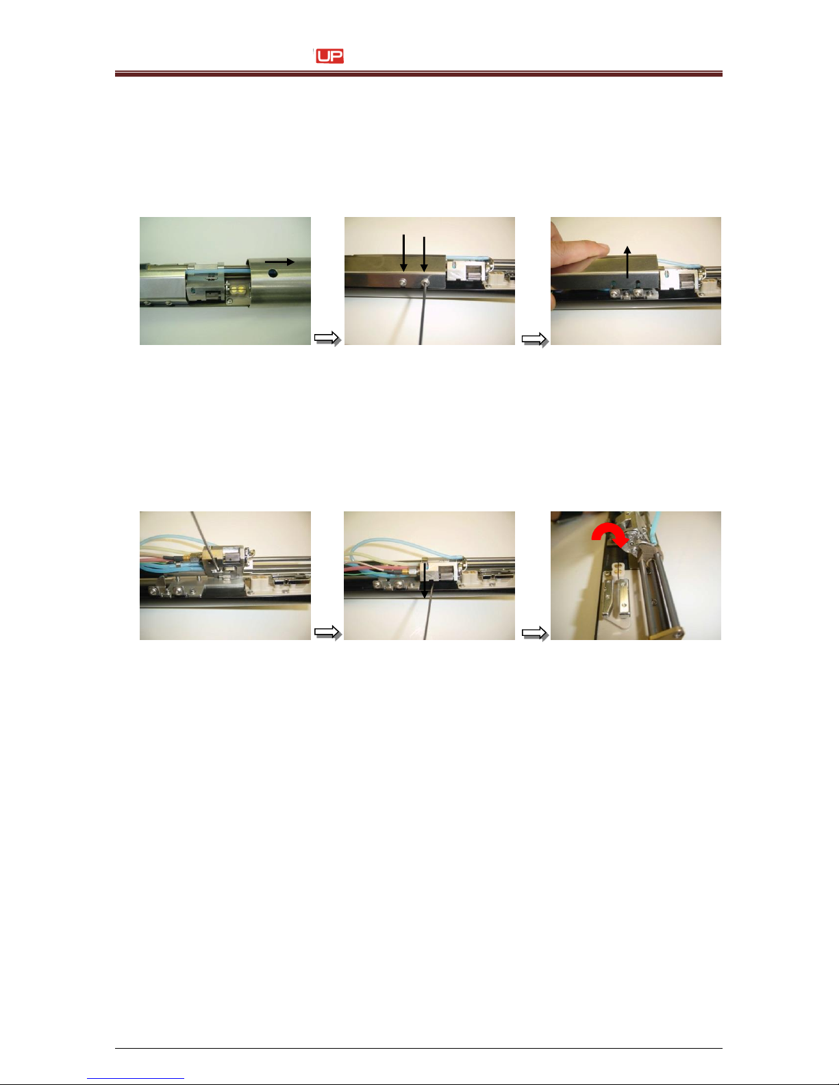
Service Manual JET3
60 Rev. 1.0
2) Cleaning of print head/electrode block with special
cleaner 77001-00020
1. Remove the print head cover. Loosen the two allen set screws at the side with an allen key
2,5 mm (metric) with one turn and remove the inner cover.
Attention:
Don’t use any kind of allen hydraulic settings with a ball head function.
This will damage the screws!
2. At the lower side of the bearing block you have to loose the allen screw with an allen
key1,5mm (metric) until you can turn the bearing block into the upper service position.
To lock this position, tighten the set screw back again.
For some types of ink, a persistent ink deposition at the guiding shaft assembly and
electrode block would occur. In this case, our company offers a special cleaner for cleaning
this area.
It is strongly recommended to turn off the printer when you cleaning the print head with this
kind of cleaner. No cleaner should be enter to the ink loop/hydraulic system.
Special Cleaner P/N: 77001-00020
Page 61
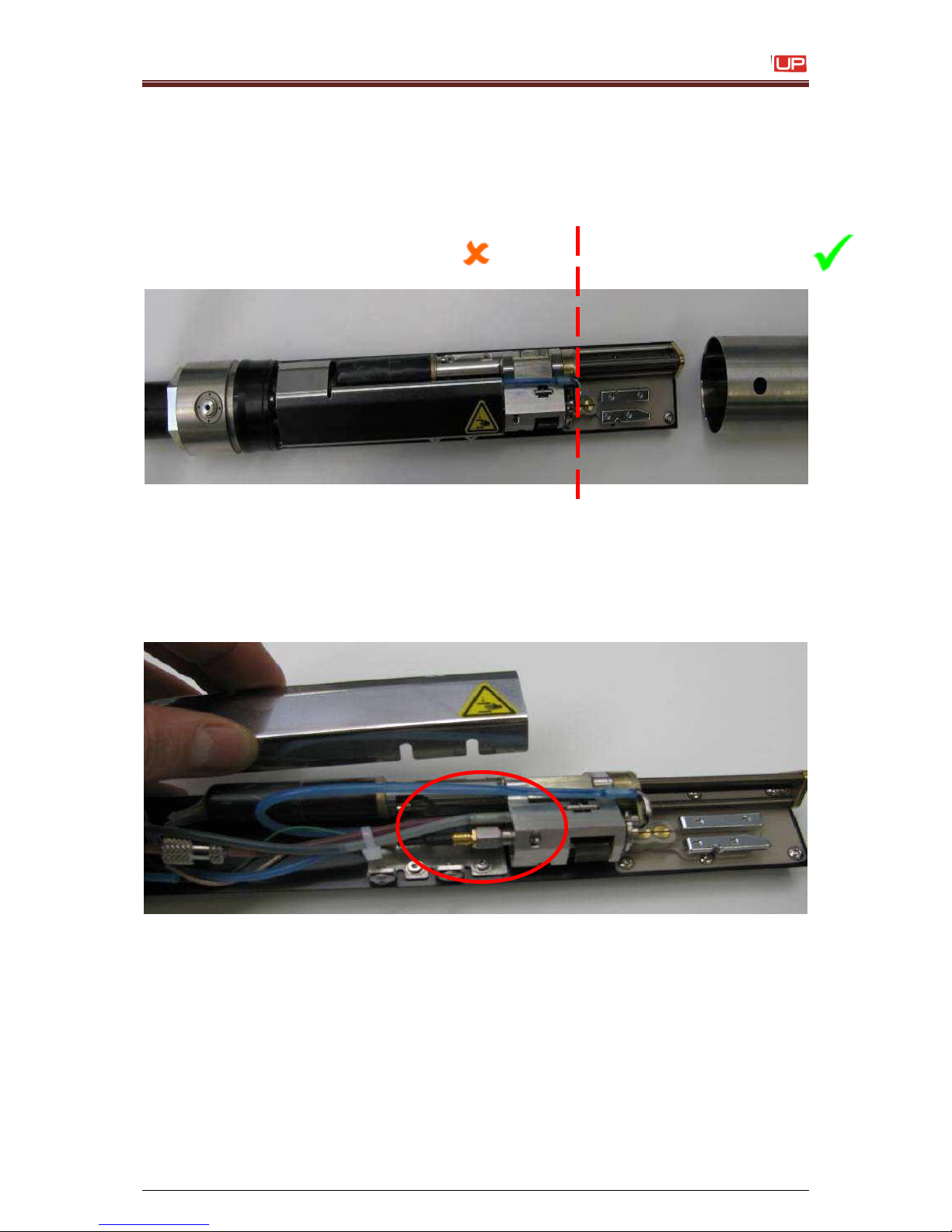
Service Manual JET3
Rev. 1.0 61
Clean the Print Head only at the correct area, right of red dotted line.
Attention:
It is forbidden to clean on the left side of the dotted line. Don’t use any kind of
solvent to clean the left side of the dotted line.
Especially in the area of the oscillator and plug connector it is not allowed to wash with
solvent. When solvent enter the oscillator, it could destroy this part or some malfunctions
could occur.
No cleaning necessary!
=> No Solvent usage!!
Cleaning Area
=> Solvent can be used!!
Page 62
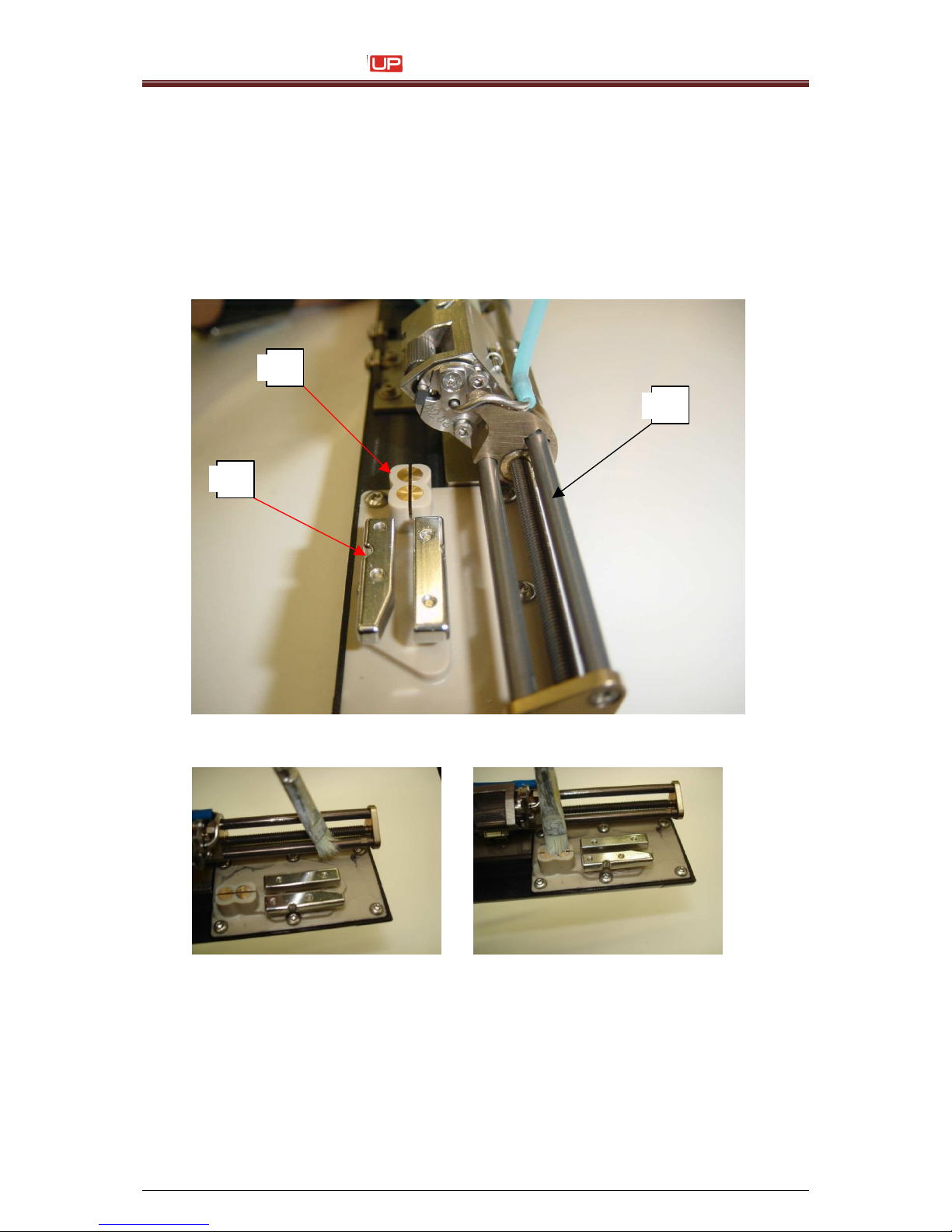
Service Manual JET3
62 Rev. 1.0
3. Decline the print head into upfront position. Fill up Special Cleaner 77001-00020
into a spray bottle and spray it to the affected parts for cleaning. Together with a small
brush you can easily remove the pollution in the cleaning area.
Important assemblies which will be affected in their functionality during persist ink
deposition:
-
1. Deflection Plates
-
2. Charge Electrode
-
3. Guiding shaft for the Gutter Tube
4. Due to some special ingredients of the cleaner, it is strongly recommended to flush all
the cleaned parts with tap water at the end of the cleaning process.
5. Rinse off the cleaned parts with original solvent again, to avoid remaining of special
cleaner at the assemblies.
2 1 3
Page 63
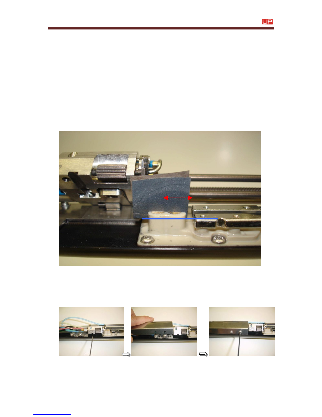
Service Manual JET3
Rev. 1.0 63
6. In some cases, there will still remain some rest of ink into the slot from the charge
electrode. This could create some error messages, e.g. phasing error or error of
drop control.
To remove this rest of ink you can use a fine sand paper. With assistance of
this fine sand paper it is possible to clean the slot of the charge electrode.
Attention:
Use only sand paper with a corn diameter of 400 and higher!
7. Bend this thin sand paper with the rough side outside. Spray some special cleaner on
the sand paper and move it inside the slot of the charge electrode. Carry out the
movement parallel to the bottom side of the charge electrode. Rinse off the charge
electrode with tap water and solvent to avoid remaining of special cleaner at the
charge electrode. Dry up all the print head parts with an airgun.
8. Rotate back the bearing block from the service position and lock them with the set screw.
9. Install the inner cover and tighten it. Don’t smash or brake any cables and pipes during
this action.
Page 64
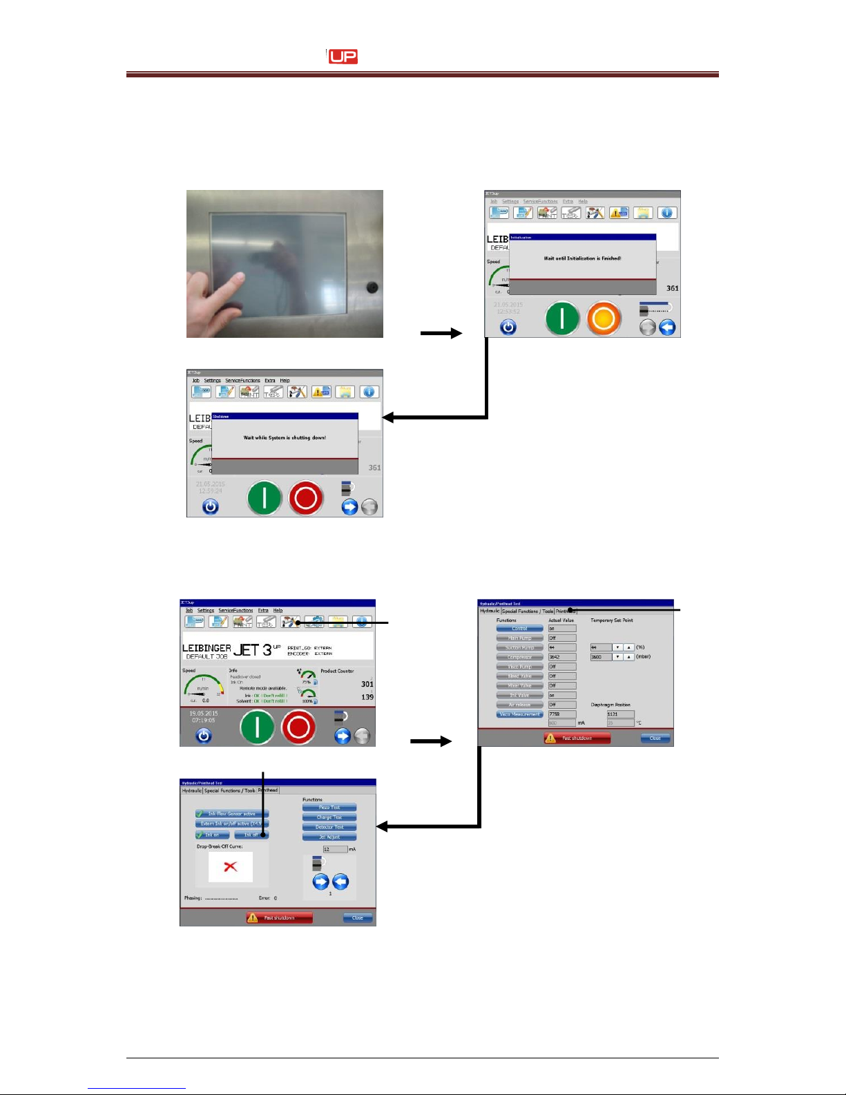
Service Manual JET3
64 Rev. 1.0
3) Cleaning of nozzle with special cleaner 77001-00020
1.
Switch on the JET3up and wait till the “bleeding cycle” of the system is finished.
2.
Click on the softkey <Hydraulic settings> (1) to change to the menu <Printhead>
(2). Press the button <Ink off> (3).
1 – Softkey <Hydraulic settings>
2 – Menu <Printhead>
3 – Button <Ink-off>
1
2
3
Page 65
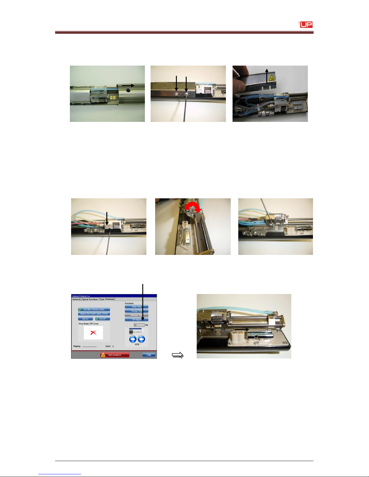
Service Manual JET3
Rev. 1.0 65
3.
Remove the print head cover. Release the retaining screws with an allen key
2.5 mm (metrical) by turning about one rotation and remove the interior cover.
Attention:
It is not allowed to use ball head allen keys,
otherwise screw heads could be damaged.
4.
Release the retaining screw for the swivel-unit with an allen key SW 1.5 mm
(metrical) until you can swing the swivel -unit upwards. Arrest the retaining screw
on the final position.
5.
Press the button <Jet Adjust>. The nozzle seal moves automatically onto the “service
position”.
Page 66
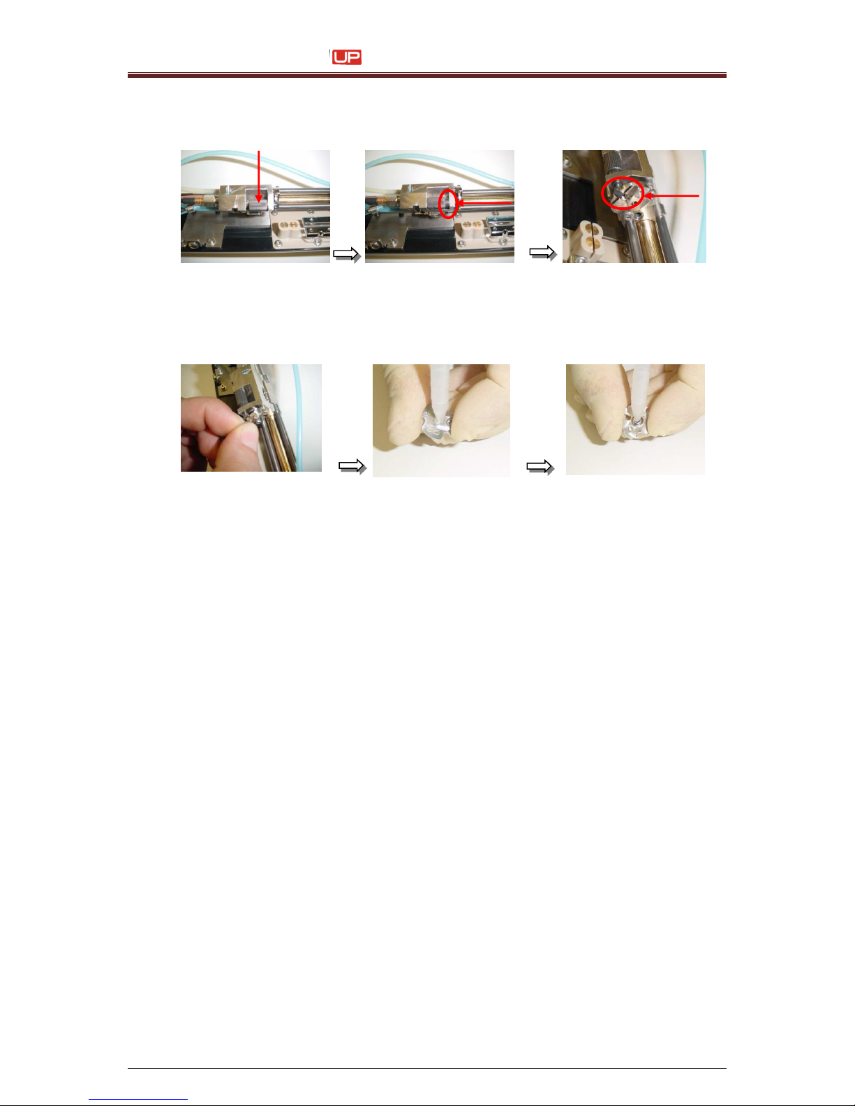
Service Manual JET3
66 Rev. 1.0
6. Turn back the knurled-head-screw to stop until the cross bolt rotates 90 °and the
nozzle adjustment is released.
7. Take out the nozzle and clean it properly from both sides with the appropriate solvent.
Wash up first the nozzle outlet, then the nozzle entry.
8. Generally it is allowed to clean the nozzle with an appropriate “ultra sonic bath”.
Especially for tenacious deposits of ink Leibinger offers a special cleaner
(77001- 00020) to clean the nozzle.
9. Clean the nozzle at first inside the ultra sonic bath with the appropriate solvent
which is used on the printer (depending of the used ink!)
10. Blow out the nozzle with clean air pressure (2 - 6 bar). Center the air-gun exactly in
the middle of the nozzle and blow out for several seconds. First against the nozzle
outlet and then against the nozzle entry. This process can be repeated for an
unlimited number of times.
11. Clean the nozzle the second time inside the ultra sonic bath, but now with the
special cleaner 77001-00020 (for round about 10min)
Page 67
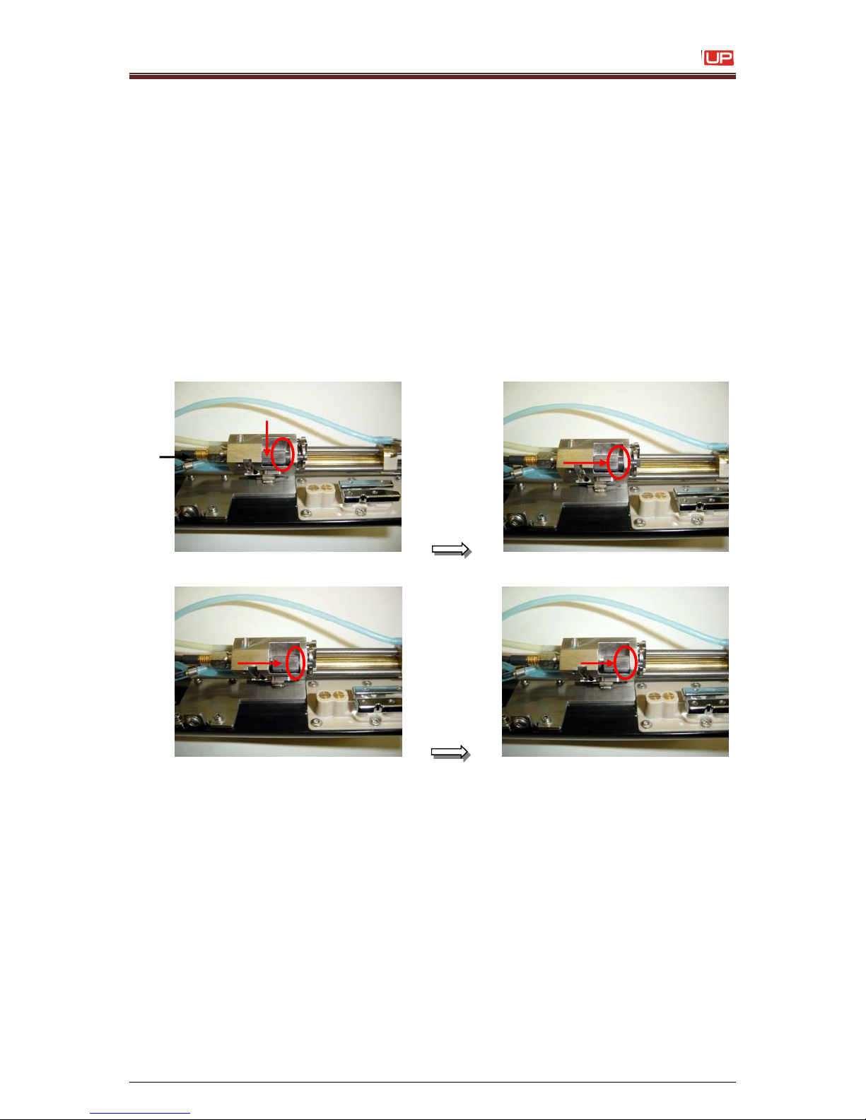
Service Manual JET3
Rev. 1.0 67
12. Due to some special ingredients of the cleaner, the nozzle must be washed up with
tap water at the end of the cleaning process.
Blow out the nozzle with clean air pressure (2 - 6 bar). Center the air-gun exactly in
the middle of the nozzle and blow out for several seconds. First against the nozzle
outlet and then against the nozzle entry. This process can be repeated for an
unlimited number of times.
13. To avoid that any remains of the special cleaner or water are still remaining on the
nozzle, wash up the nozzle once more with solvent and dry it with air pressure.
14. Insert the nozzle and turn forward the knurled-head-screw to the end position.
Thereby the cross bolt rotates 90 °and arrests the nozz le. Afterwards turn back the
knurled-head screw about one rotation.
Page 68
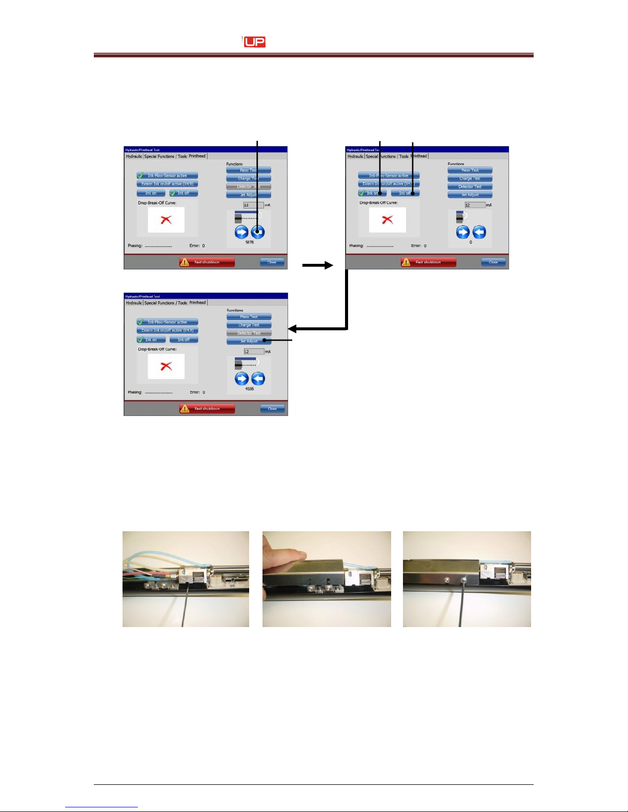
Service Manual JET3
68 Rev. 1.0
15.
Close the nozzle seal completely by pressing the button <arrow> (1).
Actuate several times in quick succession the buttons <Ink on>/<Ink off> (2).
Press the button <Jet Adjust> (3) and wait until the nozzle seal is open.
Check the jet position inside the gutter.
1 – Button <arrow close nozzle>
3 – Button <Jet adjust>
2 – Buttons <Ink on>/<Ink off>
16.
Close the nozzle seal again and fix the swivel-unit at the starting position. Put on and
fasten the interior cover. By putting on the interior cover do not damage any cable or
tubes.
17.
Carry out a final check about the correct jet position and functionality.
1
3 2 2
Page 69
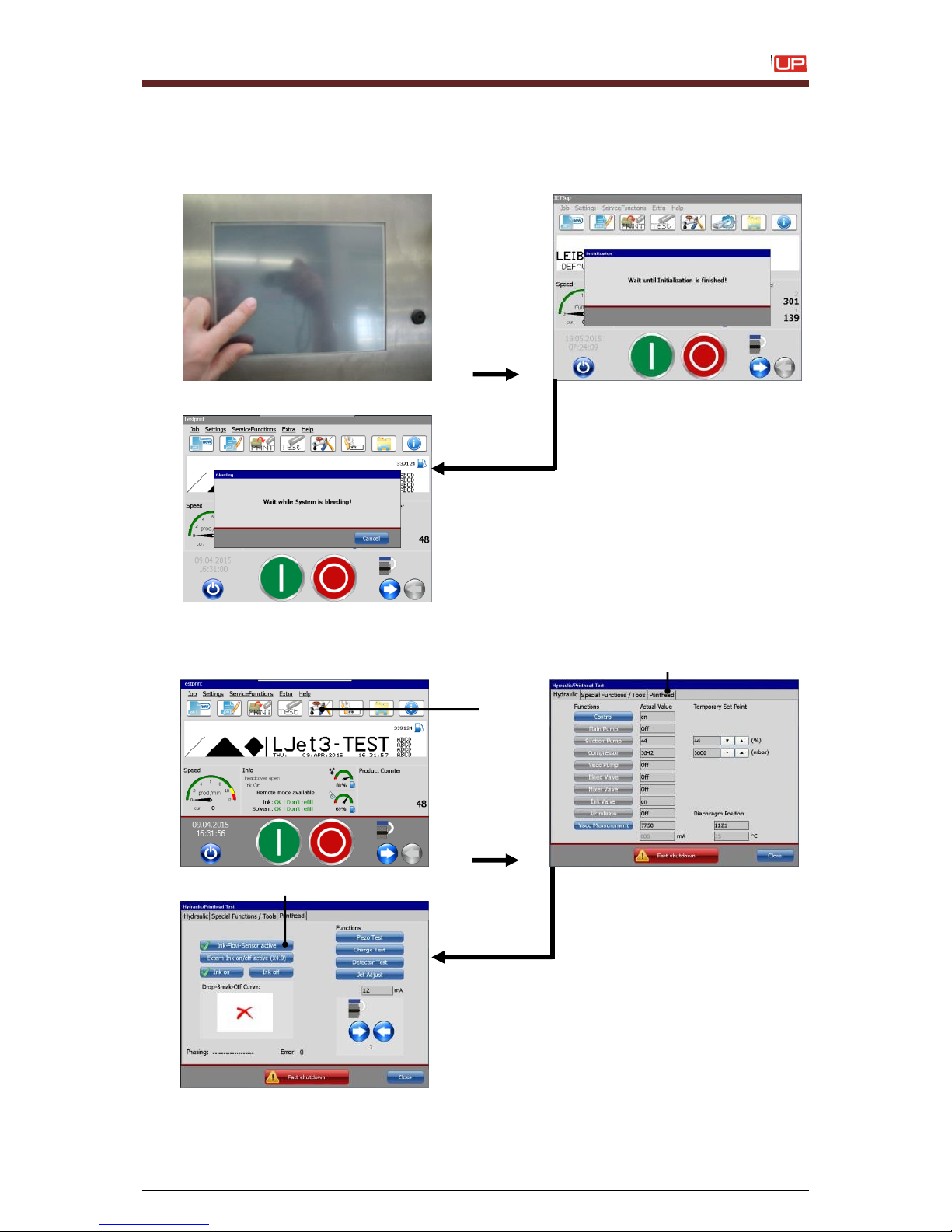
Service Manual JET3
Rev. 1.0 69
4) Print head adjustment
1. Switch on the JET3up and wait while the system is bleeding.
2. Touch the softkey <Hydraulic settings> (1) and change to the menu <Printhead> (2).
Turn off the function <Ink-Flow-Sensor> (3).
1 – Softkey <Hydraulic settings>
2 – Menu <Printhead>
3 –Function <Ink-Flow-Sensor>
2 3 1
Page 70
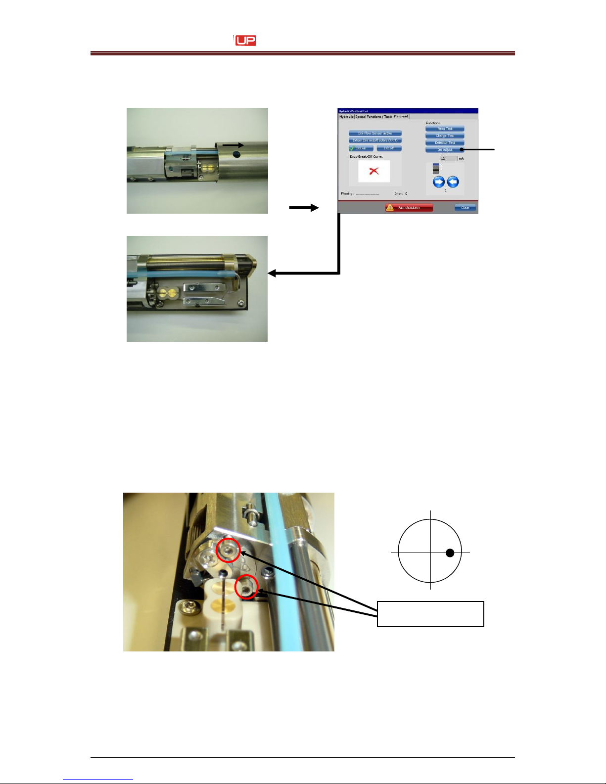
Service Manual JET3
70 Rev. 1.0
3. Remove the head cover and press the button <Jet Adjust> (1).
The nozzle seal opens automatically to the <Jet Adjust position> (4200)
1 – Button <Jet adjust>
4. Align the ink stream with the two adjusting screws according to the sketch into the
gutter tube.
Required tools:
6-fold magnifying Glasss
Allen key (SW 1,5 mm)
Attention:
It is not allowed to use a golf ball head allen key.
The screw heads could be damaged!
1
Adjusting screws
Page 71
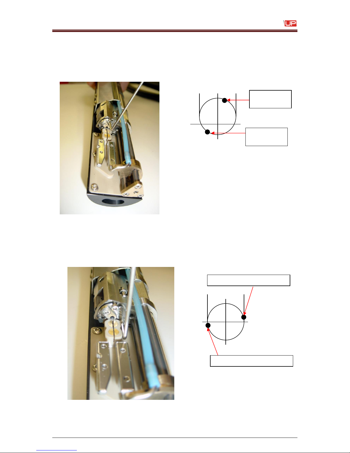
Service Manual JET3
Rev. 1.0 71
Rotating the upper adjusting screw CW, the ink stream is moving a little bit angular in
direction of the gutter tube top edge. Rotating the screw CCW, the ink stream is moving a
little bit angular in the direction bottom edge of the gutter tube.
(Viewing direction from nozzle to gutter)
Rotating the edgeways adjusting screw CW, the ink stream is moving
a little bit angular upwards in direction of left edge of gutter tube. Rotating the screw CCW,
the ink stream is moving a little bit angular downwards in direction of left edge of gutter
tube.
(Viewing direction from nozzle to gutter)
Gutter tube
top edge
Gutter tube
bottom edge
Right edge of gutter tube
Left edge of gutter tube
Page 72
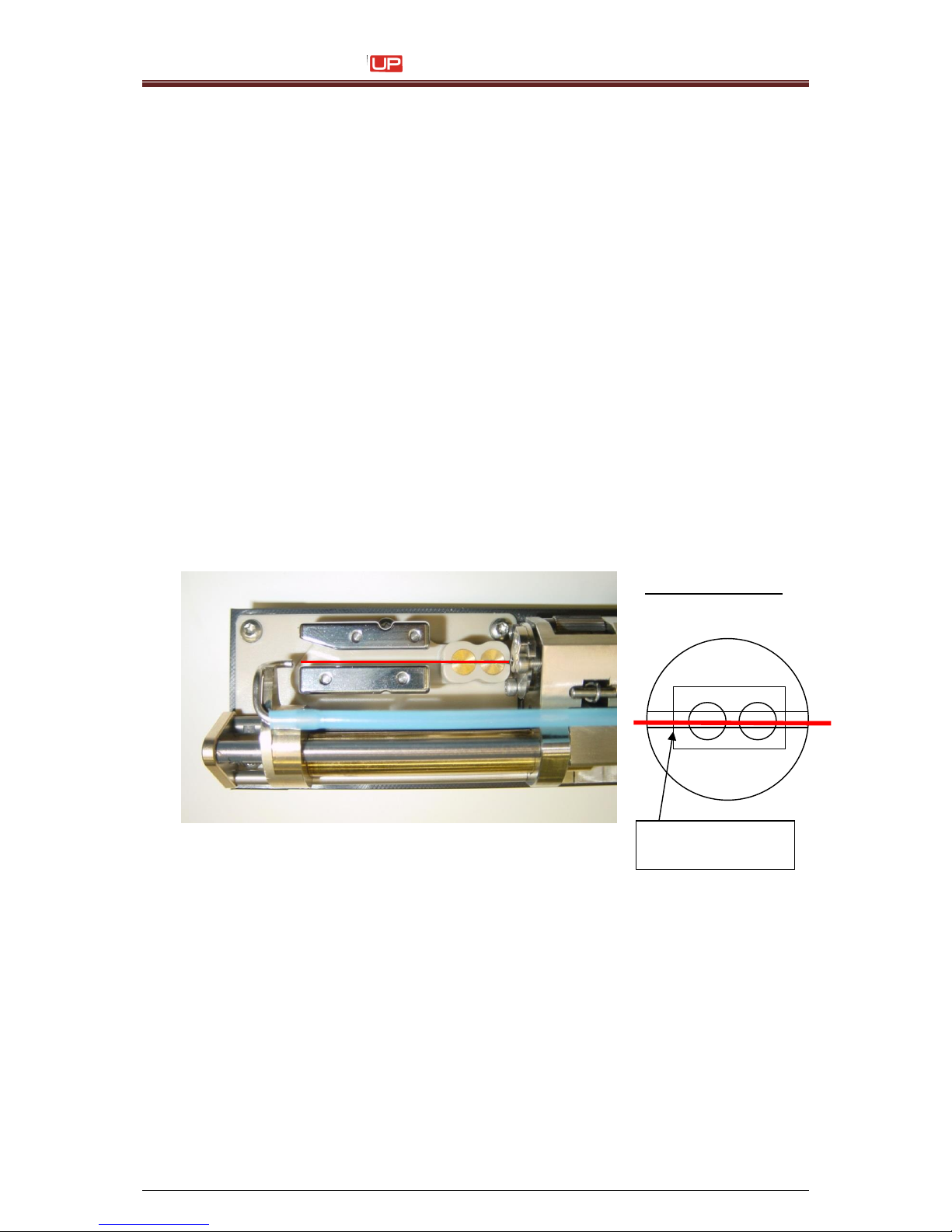
Service Manual JET3
72 Rev. 1.0
Hint: Due to the constructional positioning of the adjustment screws, there will be
always a movement like a skew during the adjustment on any screw. Due to this
existing skew, usually both adjusting screws must be adjusted for the correct attitude.
5. After adjustment of the entire drop production unit into the charging tunnel
and deflecting plates, it has to be adjusted in such a way, that the ink stream knew
parallel and concisely with the internal left of the charging tunnel.
(Viewing direction: From nozzle toward gutter tube).
The ink stream should run absolutely parallel to the deflecting plate.
Required tools:
6-fold magnifying Glasss
Allen key (SW 1,5 mm) or Torx (T6)
During the optical evaluation of the radiation situation it is important that
the point of view is directed exactly perpendicularly from above via the charging tunnel
and ink stream, in order to exclude a parallax error to a large extent.
Attention:
It is not allowed to use a ball head allen key.
The screw heads could be damaged!
Adjusting position
Left edge of
charging tunnel
Page 73
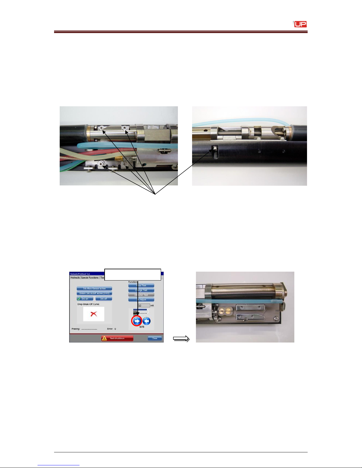
Service Manual JET3
Rev. 1.0 73
Sequence of adjustment:
- Open the 5 retaining screws of the mounting plate until the plate can be moved
lightly by hand.
- Relocate the mounting plate until the ink stream reaches the final adjustment
position.
- Tighten the retaining screws and check the jet position again.
Retaining screws (fix with Allen key (SW 1,5 mm) or Torx (T6)).
6. Open the nozzle seal completely with the <arrow> button unless the ink stream
goes inside the charging tunnel and the nozzle seal reaches the final position.
The ink stream should be concentric inside the charging tunnel and parallel to the
deflection plates. If not, readjust the position again.
<arrow> button
Page 74
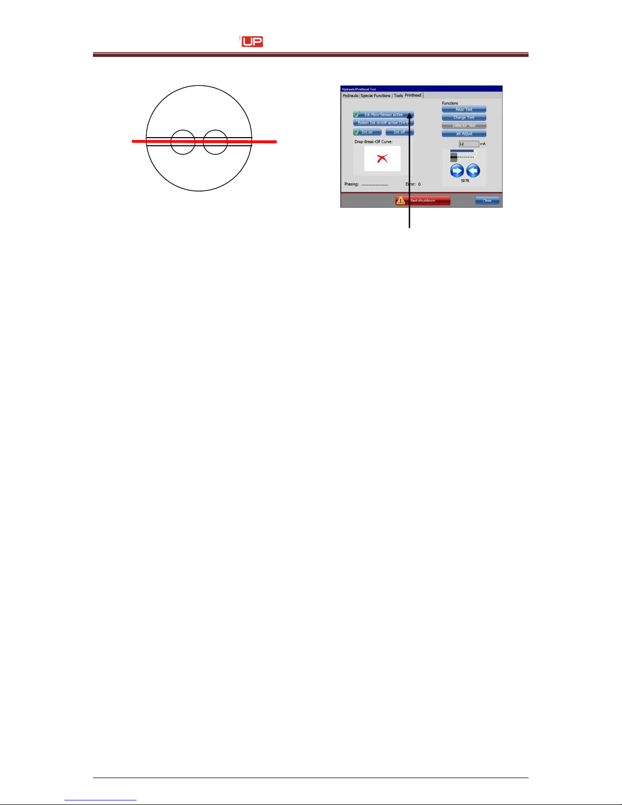
Service Manual JET3
74 Rev. 1.0
Switch on the button <Ink-Flow-Sensor>
7. Close and open again the nozzle seal. Do a final check up for the correct position of
the ink stream.
Page 75
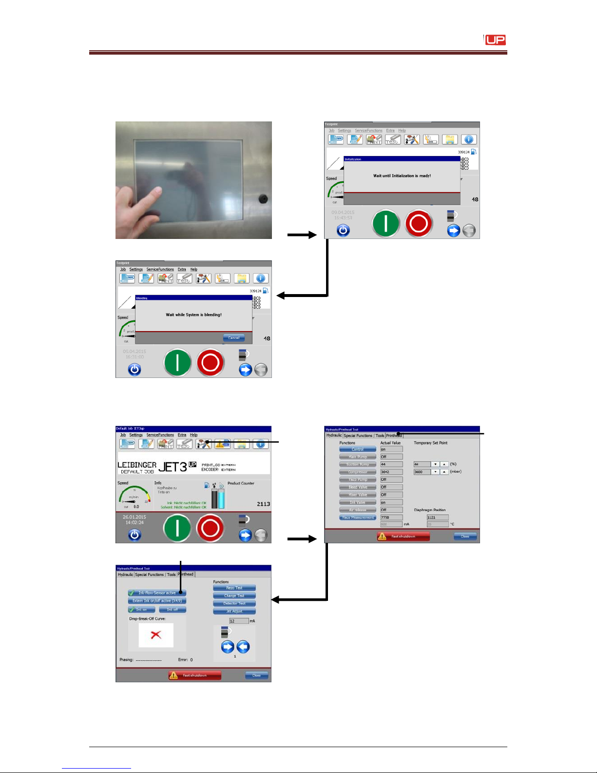
Service Manual JET3
Rev. 1.0 75
5) Exchange the oscillator
1. Start up the JET3up via the touch-display and wait until the initialization and the
bleeding is finished.
2. Touch the softkey <Hydraulic settings> (1), open the <Printhead> (2) menu and
deactivate the <Ink-flow-sensor> (3)
1 – Softkey <Hydraulic settings>
2 – Menu <Printhead>
3 – Function <Ink-Flow-Sensor>
3 1 2
Page 76
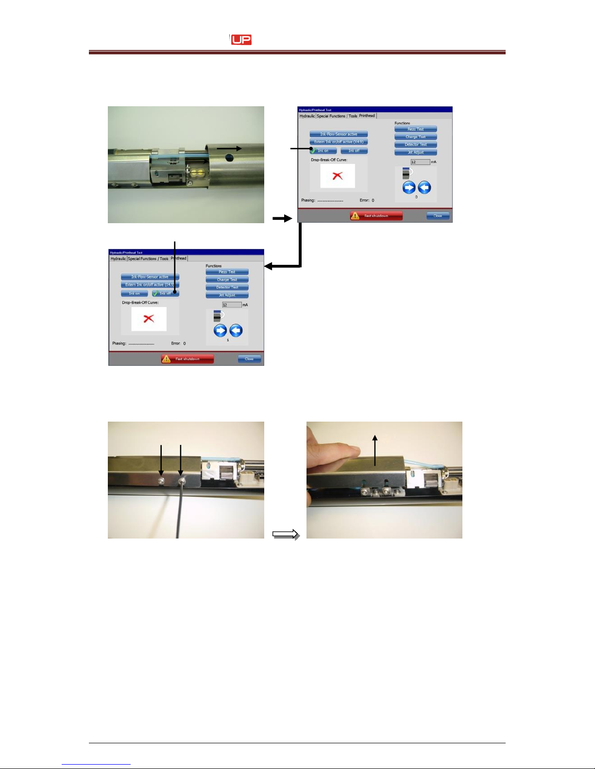
Service Manual JET3
76 Rev. 1.0
3. Open the headcover and switch the button <Ink off> (1)
1 – Softkey <Ink off>
4. Remove the inner-cover, but open the allen-screws (2,5 metric) only one turn.
1
1
Page 77
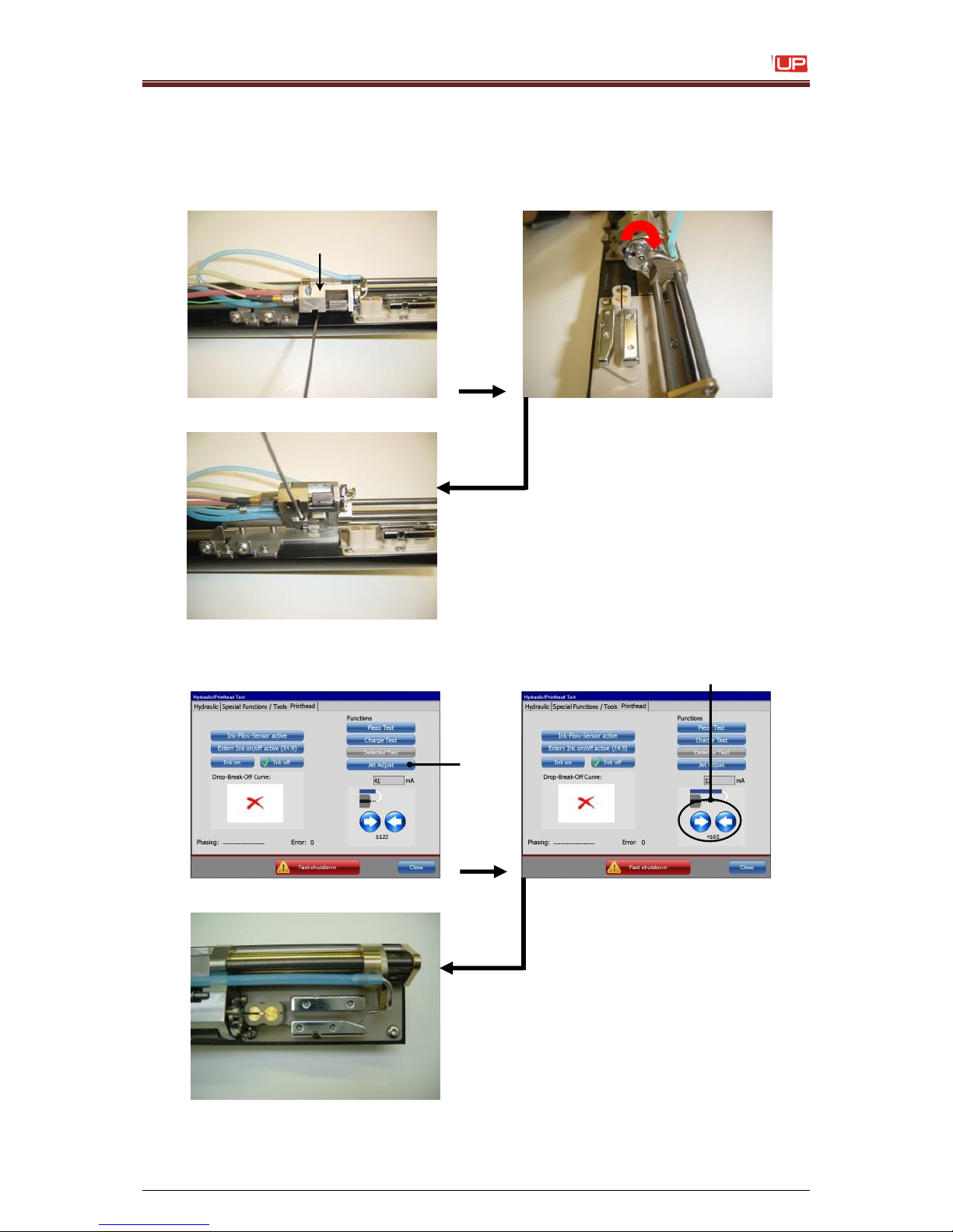
Service Manual JET3
Rev. 1.0 77
Attention:
Never use a balled head allen key, otherwise you are damaging the screws!!!
5. Open the allen screw (1,5 metric) from the drop production unit, until it is possible to
bring it into the service-position. Then close the screw until the unit is locked.
6. Touch the <Jet Adjust> button (1). Now the gutter tube is moving automatically to a
pre defined service-position (4200) (2).
1 – Button < Jet Adjust >
2 – Displayfield <Service position
1
2
Page 78
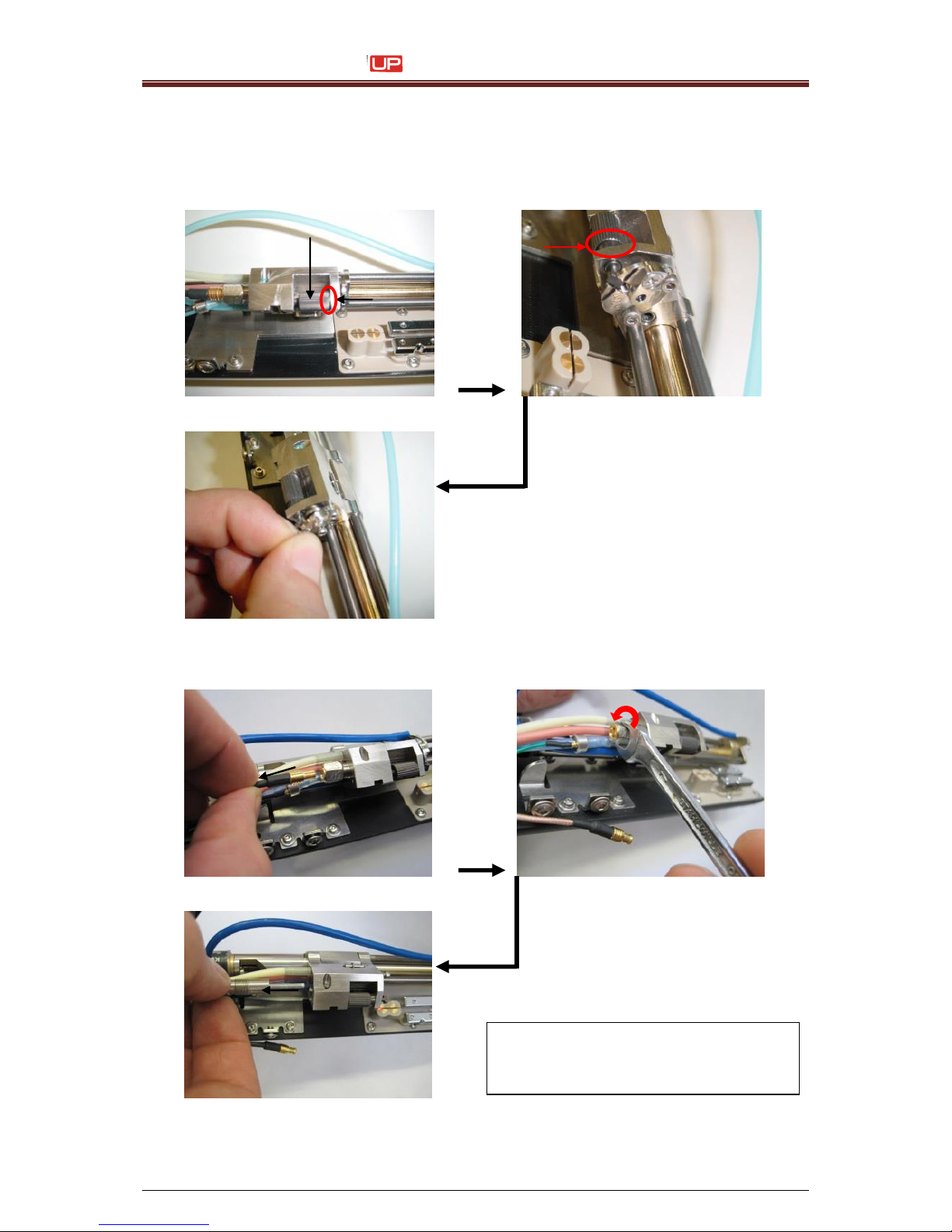
Service Manual JET3
78 Rev. 1.0
For the next steps you have to incline the head a little bit down, that the ink or
solvent can leak out of the print head!
7. Wind back the knurled-head screw to stop until the cross bolt centre turns on 90°. Is
the nozzle adjustment released you can take out the nozzle.
8. Unplug the oscillator and release it with a 7mm open-end wrench key.
Unscrew the oscillator by hand and take it out of the drop production unit.
Attention:
Do not bent the oscillator
otherwise it could be damaged!!!
Page 79
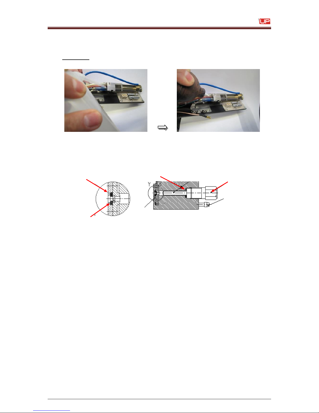
Service Manual JET3
Rev. 1.0 79
9. Flush the hole (in the drop production unit) for the oscillator with solvent and dry it with
clean compressed air.
Attention : Don’t lose the oscillator o-ring during drying with compressed air.
Be sure that no dirt is coming into the open system.
10. Pay attention to the right installation position from the oscillator o-ring.
(drawing for a 96KHz unit)
!!! Don’t forget the adapter ring and the second o-ring in a 64 KHz unit !!!
Attention: Do not bent the oscillator otherwise it could be damaged!!!
11. Clean the new oscillator. Install the oscillator and tighten it well only by hand.
Attention:
It is prohibited to flush the oscillator with solvent!!
Solvent could enter inside and damage the piezo!!
Nozzle plate
Nozzle seal
Oscillator O-Ring
Oscillator
Page 80
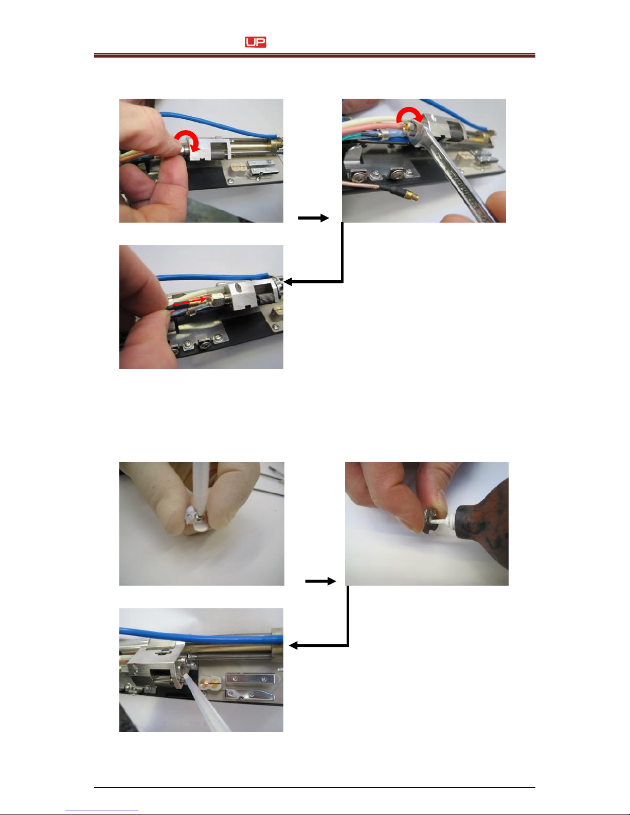
Service Manual JET3
80 Rev. 1.0
Fasten slightly the oscillator with a 7mm open-end hydraulic settings.
Plug in the oscillator cable.
12. If necessary clean the nozzle from both sides with appropriate solvent.
Blow down the nozzle with clean air (pressure 2-6 bar). Focus the air gun exactly in the
middle of the nozzle and blow down for several seconds. First against the nozzle outlet
and then against the nozzle entry. This can be repeated for an unlimited number of
times.
Page 81
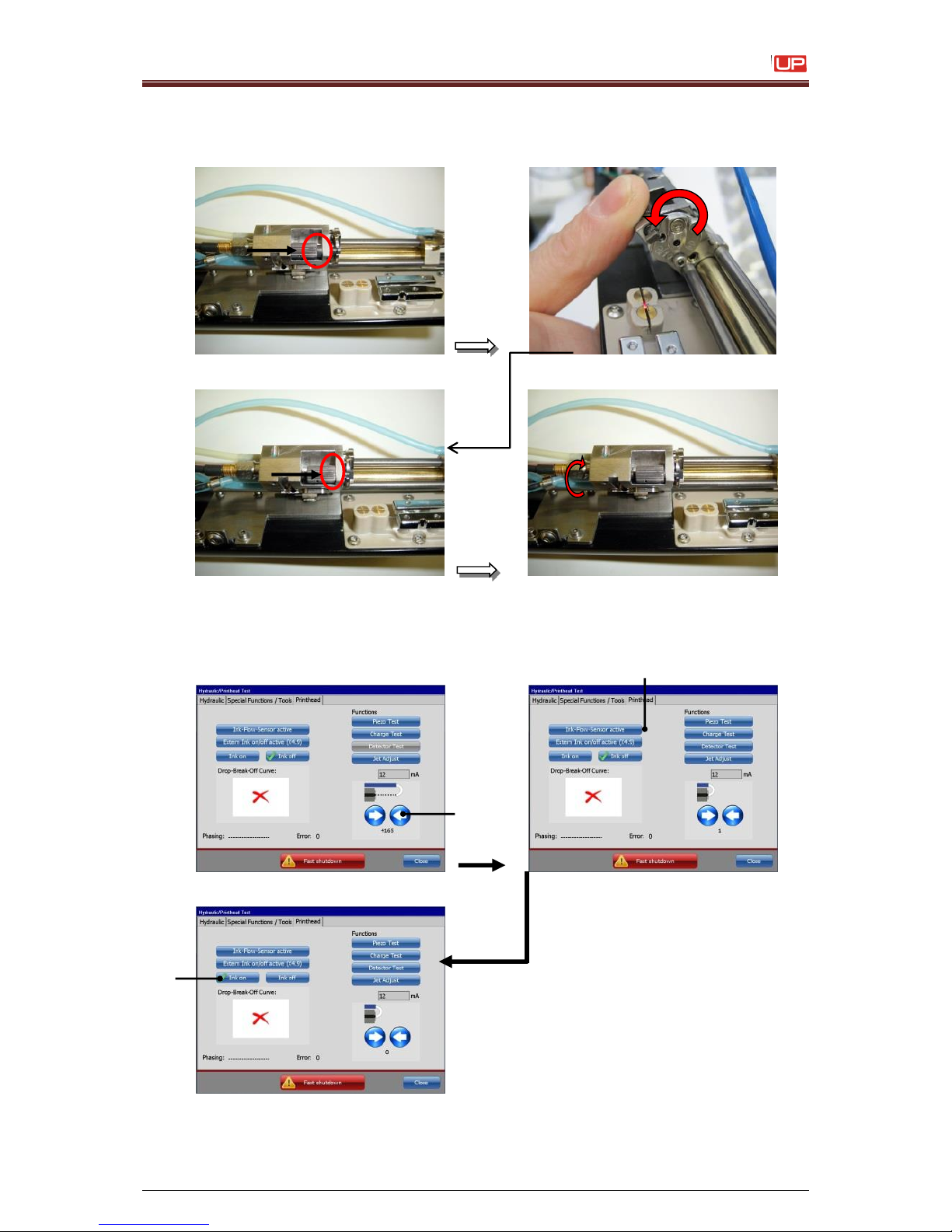
Service Manual JET3
Rev. 1.0 81
13. Replace the nozzle and turn the knurled-head-screw to stop position. Thereby the
cross bolt centre turns on 90° and arrests the nozzle.
Afterwards turn back the knurled-head-screw about one rotation.
14. Close the gutter tube by pushing the button <arrow> (1) and activate the
<Ink-flow-sensor> (2) and switch the button <Ink on> (3).
1 – Button <arrow>
2 – Button <Ink-Flow-Sensor>
3 – Button <Ink on>
1
3
2
Page 82
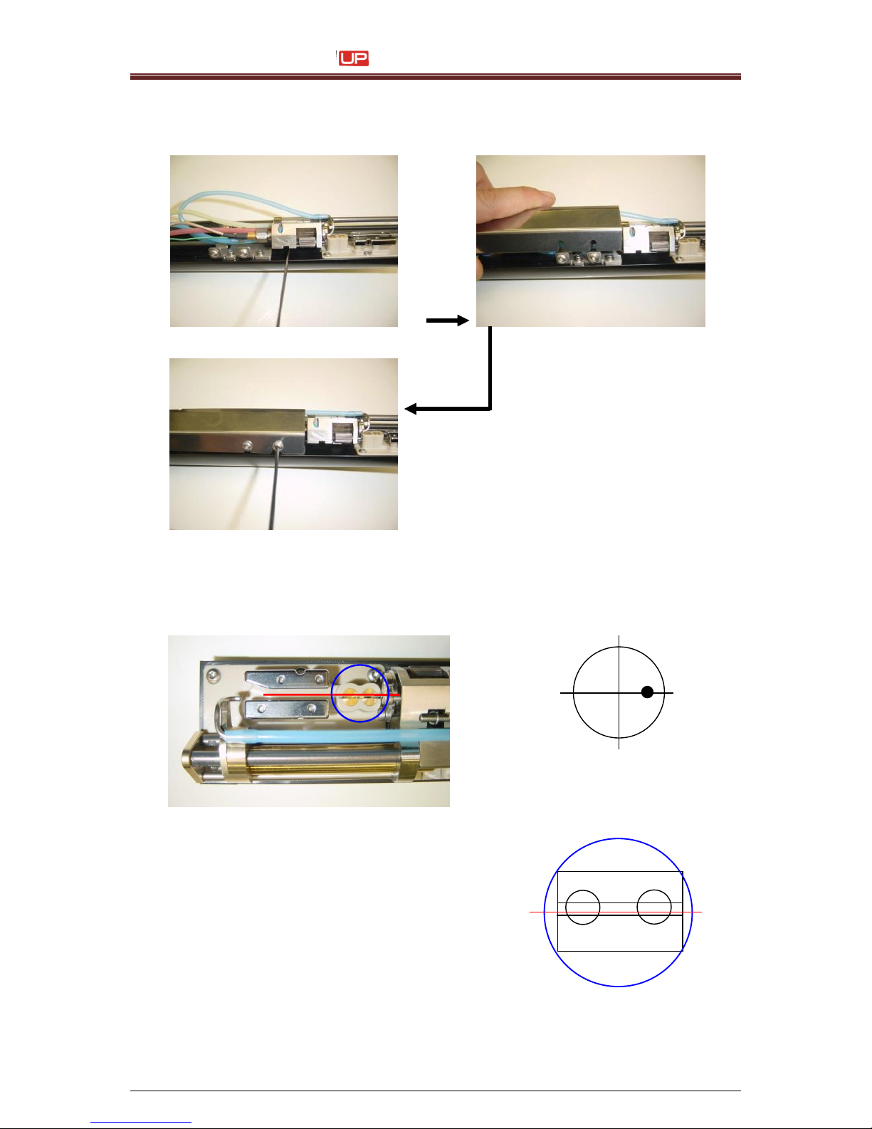
Service Manual JET3
82 Rev. 1.0
15. Bring the drop production unit into the print position and put on and fasten the innercover.
16. Finally check the correct position from the jet and the functionality.
Page 83
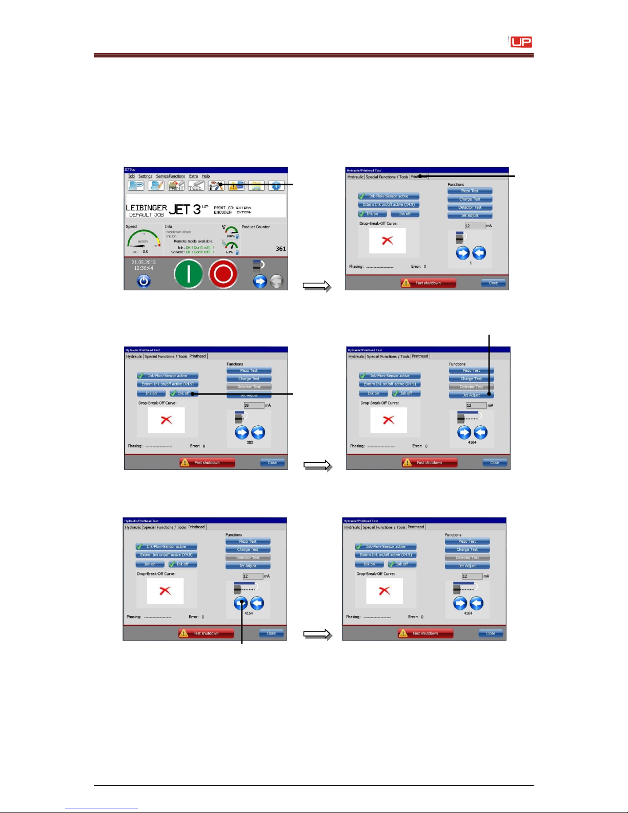
Service Manual JET3
Rev. 1.0 83
6) Exchange gutter tube
1. Switch on the JET3up and wait until initializing is finished.
2. Select the softkey <Hydraulic settings> (1) and switch to tab <Printhead> (2).
3. Push the button <Ink off> (1) and afterwards open the nozzle by pushing
the button <Jet Adjust> (2).
4. Open the nozzle completely with the <arrow> (1) button.
2
1
1 1 2
Page 84
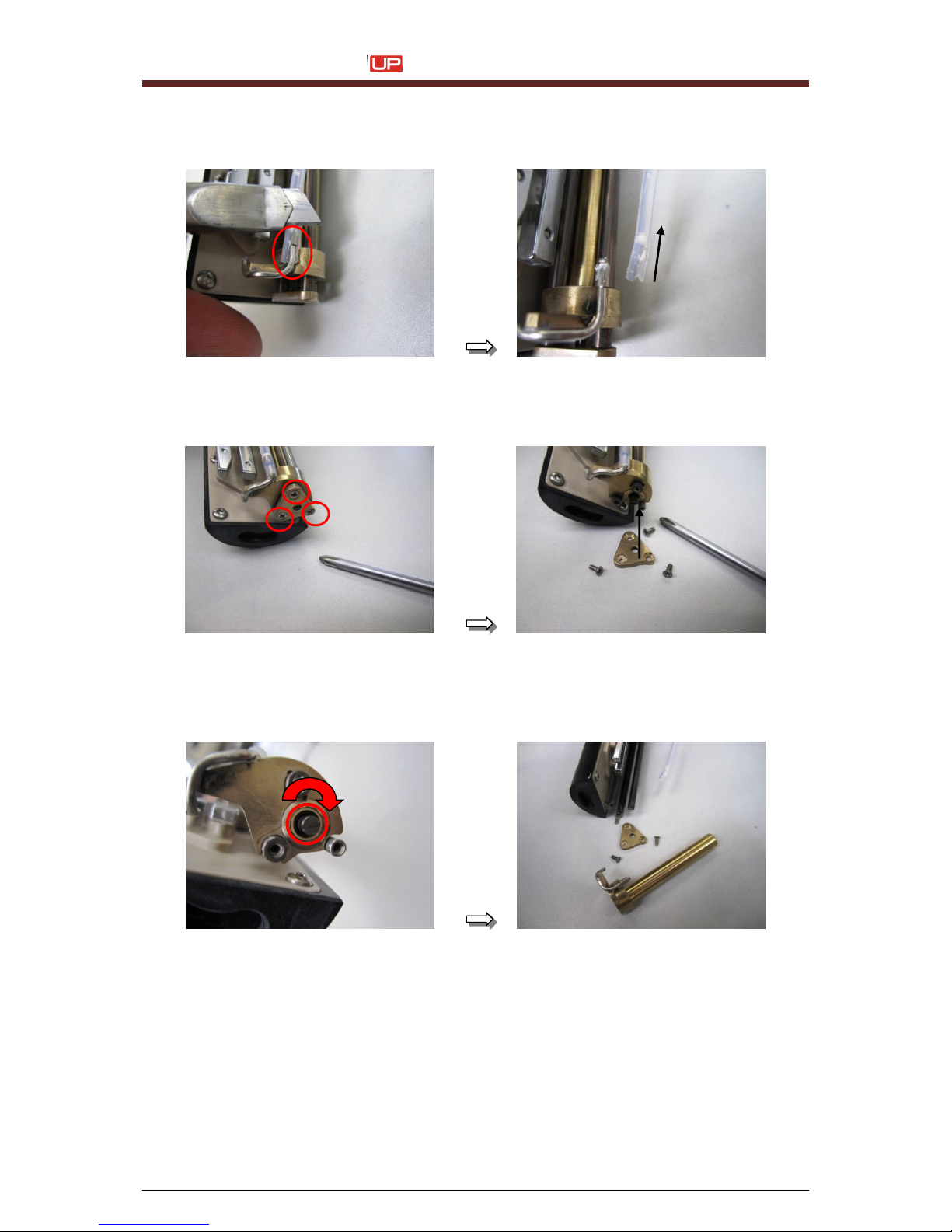
Service Manual JET3
84 Rev. 1.0
5. Put off the headcover and slice of the flexible tube from the gutter tube.
ATTENTION: The gutter tube should not be damaged!
6. Screw out the three cross head screws with a phillips-type screwdriver and put of the
retaining plate.
7. Rotate the motor spindle clockwise with a slotted head screwdriver to screw out the
gutter tube.
ATTENTION: The thread should not be damaged!
Page 85
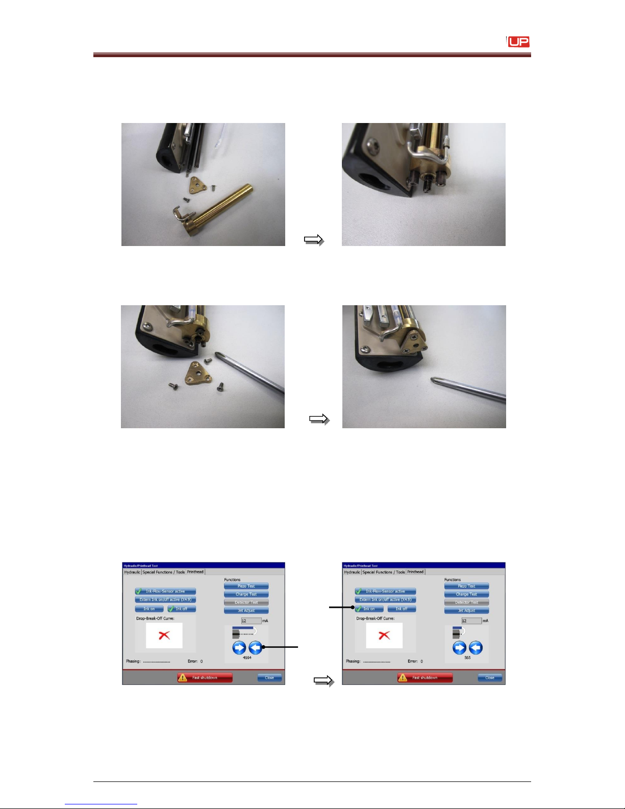
Service Manual JET3
Rev. 1.0 85
8. Put in the new gutter tube and rotate the motor spindle counter clockwise to screw in
the gutter tube.
ATTENTION: The thread should not be damaged!!!
9. Put on the retaining plate and screw in the three cross head screws by using a phillipstip screwdriver. Use Loctite as threadlocker. (The retaining plate can not be twisted.)
10. Cut of the inside end of the flexible tube and put it on the gutter tube.
11. Close the nozzle completely with the button <arrow> (1).
Checkup that the nozzle is really closed. (Do not get dizzy because of the wrong value
of the encoder. This value cannot be the right because the spindle and position of the
gutter tube have been changed.) Afterwards push button <Ink on> (2).
1 – Button <arrow>
2 – Button <Ink-on>
1
2
Page 86

Service Manual JET3
86 Rev. 1.0
12. Close the <Hydraulic> menu and switch off the JET3up. Plug off the power supply
and plug in again after a few seconds. During the booting process the values of the
nozzle encoder were set to zero and the shown value is the right again.
13. Open the nozzle and checkup the ink stream position.
Page 87
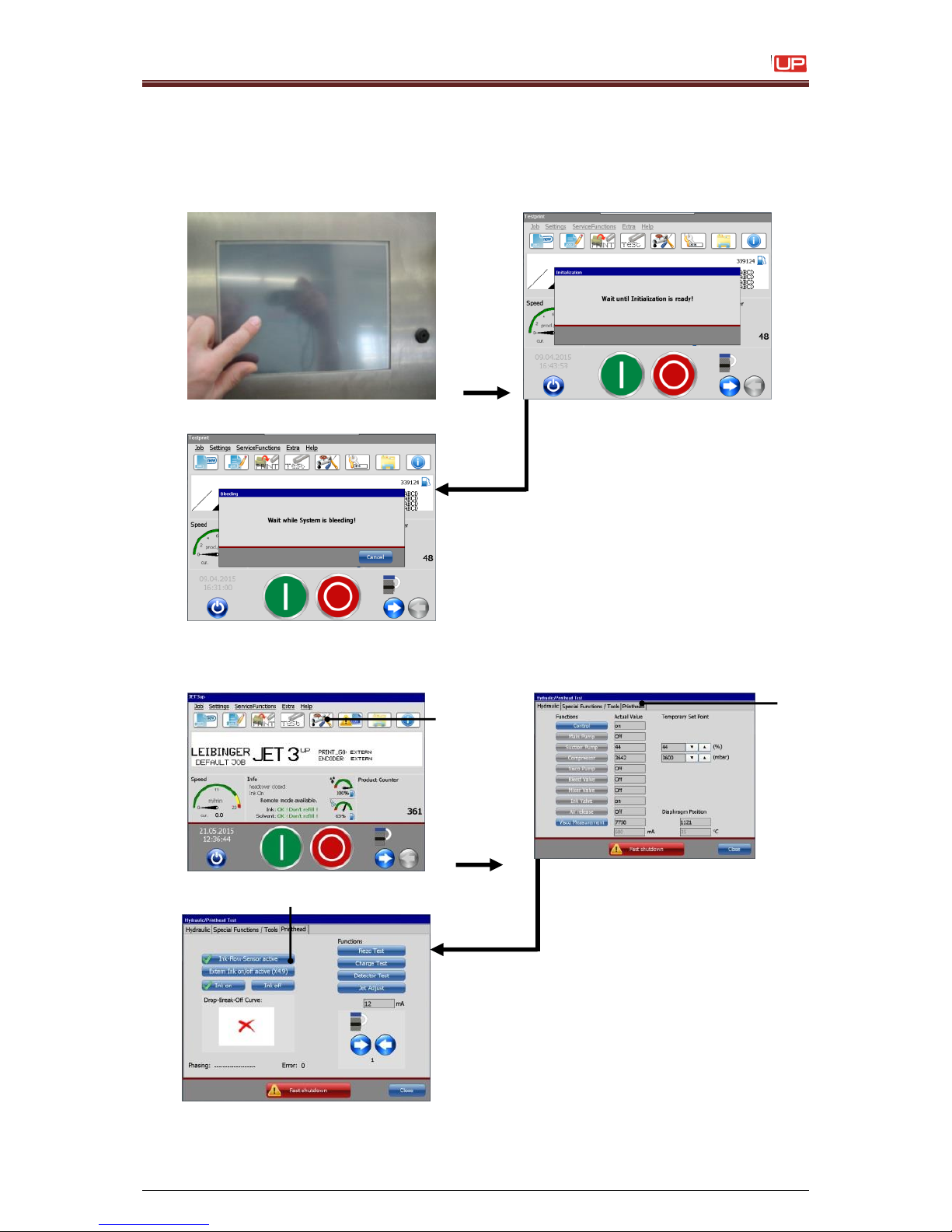
Service Manual JET3
Rev. 1.0 87
7) Exchange suction tube on print head
1. Start up the JET3up via the touch-display and wait until the initialization and the
bleeding is finished.
2. Touch the softkey <Hydraulik settings> (1), open the menu <Printhead>-(2) and
deactivate the <Ink-flow-sensor> (3).
1 – Button <arrow>
2 – Menu <Printhead>
3 – Button <Ink Flow Sensor>
1 2 3
Page 88
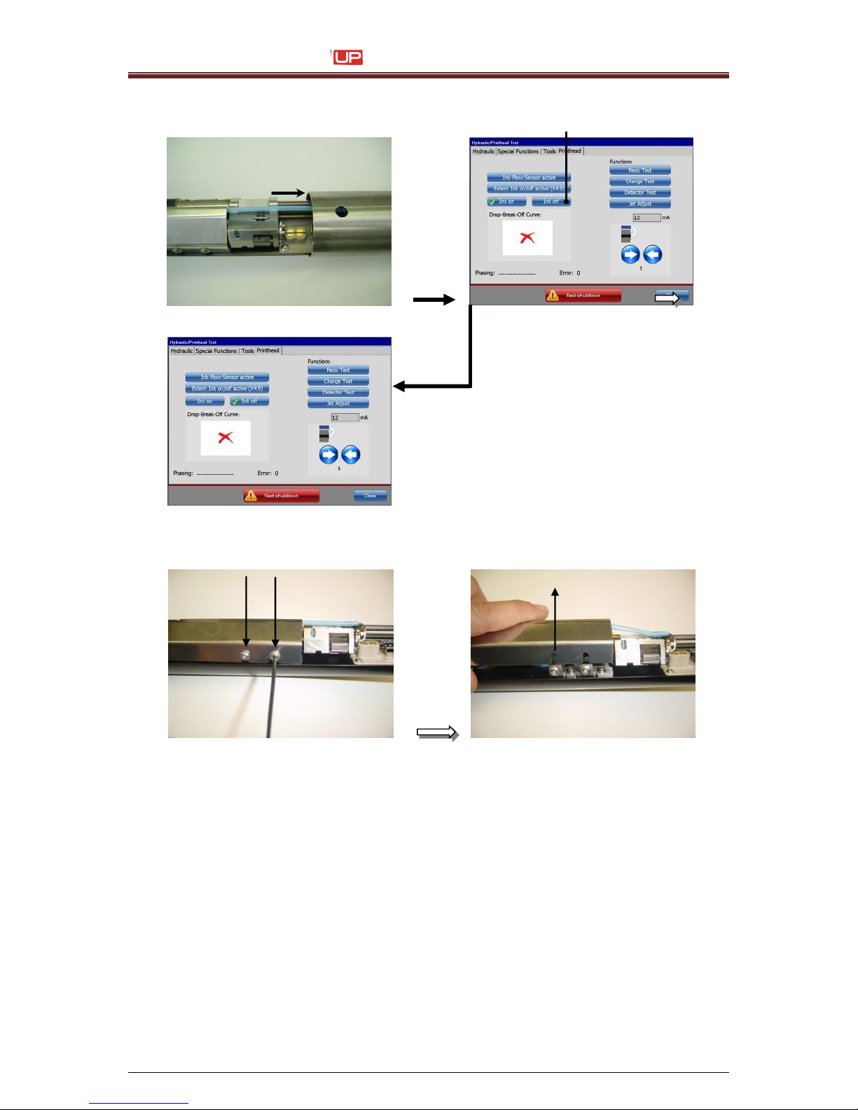
Service Manual JET3
88 Rev. 1.0
3. Open the headcover and switch the button <Ink off> (1).
4. Remove the inner-cover, but open the Allen-screws (2,5 metric) only one turn.
Attention:
Never use a balled head allen key, otherwise the
screws could be damaged!!!
1
Page 89
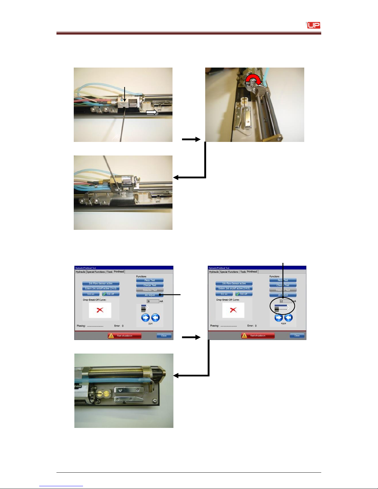
Service Manual JET3
Rev. 1.0 89
5. Open the allen screw (1,5 metric) from the drop production unit, until it is possible to
bring it into the service-position. Then close the screw until the unit is locked.
6. Touch the <Jet adjust> button (1). Now the gutter tube is moving automatically to an
pre defined service-position (4200) (2).
1 – Button <Jet Adjust>
2 – Display field <Service Position>
1
2
Page 90
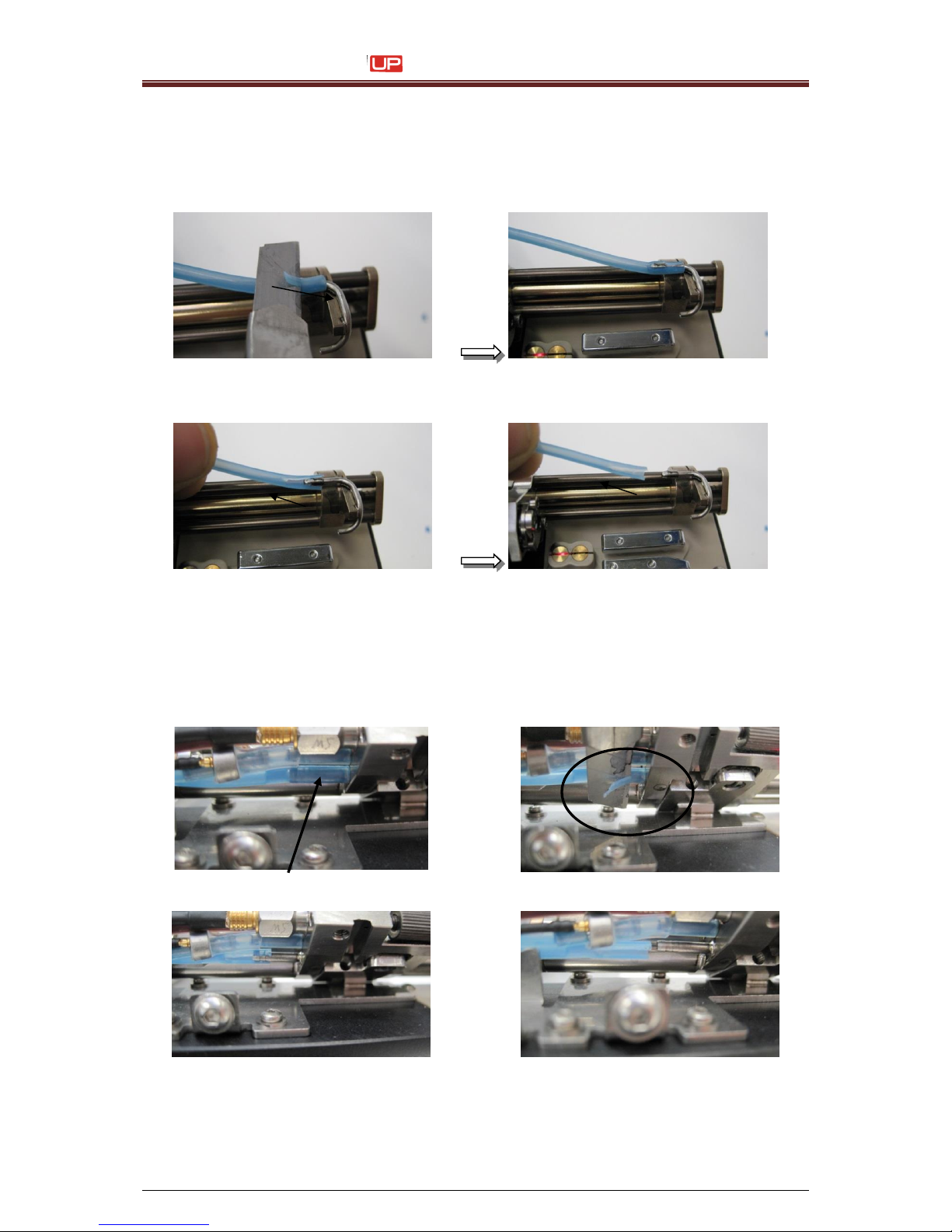
Service Manual JET3
90 Rev. 1.0
7. Cut the old suction tube horizontal very carefully (stripping off with a knife) on the gutter
tube.
Attention:
Do not scuff or damage the gutter !!!
Remove the tube carefully by hand!!!
8. Cut also the old suction tube horizontal (stripping off with a knife) on the drop
production unit.
Attention: Do not scuff or damage the fitting !!!
Page 91
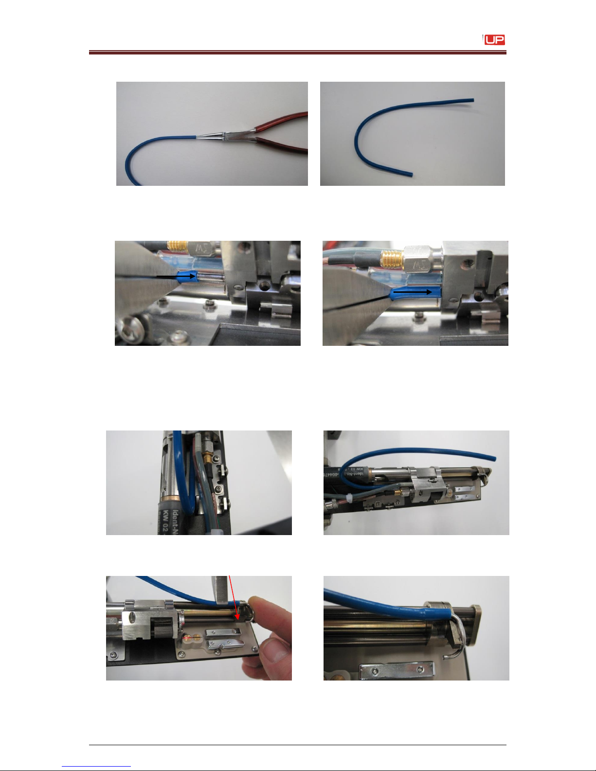
Service Manual JET3
Rev. 1.0 91
9. Widen the tube on both sides with a long-nosed pliers
10. First connect the short side of the suction tube with the drop production unit!
It is much easier to do this with the tool (tongs), which you can order from Leibinger.
11. Connect the other side from the suction tube with the gutter.
The suction tube must have a pre-bending like you can see on the picture.
Attention:
The gutter tube is only fixed by laser-welding, don’t break it!!!
Upheld the gutter with the finger, while you connect the suction tube onto the gutter!
Page 92
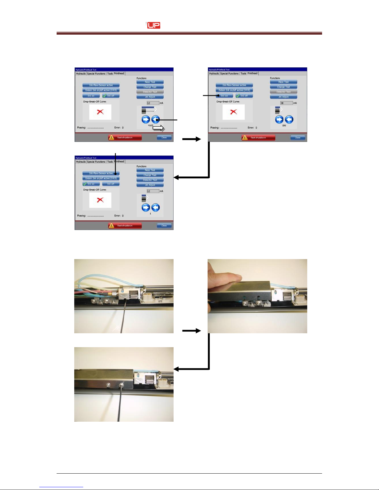
Service Manual JET3
92 Rev. 1.0
12. Close the gutter tube with the <arrow> button (1) and switch the button <Ink on> (2)
and activate the <Ink-flow-sensor> (3).
1 – Button <arrow>
2 – Button <Ink on>
3 – Button <Ink flow sensor>
13. Bring the drop production unit into the print position.
14. Check the JET3up for the right position in the gutter and the electrodes.
3
2
1
Page 93
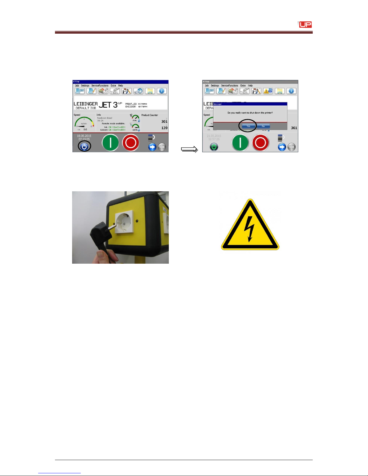
Service Manual JET3
Rev. 1.0 93
8) Exchange the electrode block
1. Switch off the JET3up.
2. Remove the mains plug.
Dangerous electrical voltage!
Contact causes serious damage through an electric shock! Disconnect the
device from the voltage supply prior to open. Remove mains plug!
Tools you need:
6-fold magnifying Glasss, Allen keys (SW 1,5 + 2,0 mm) and Torque Allen
key with Blade for Torx (T6 + T8).
You will find these keys in our Spare Part and Accessories Catalog!
Switch off the JET3up
Page 94
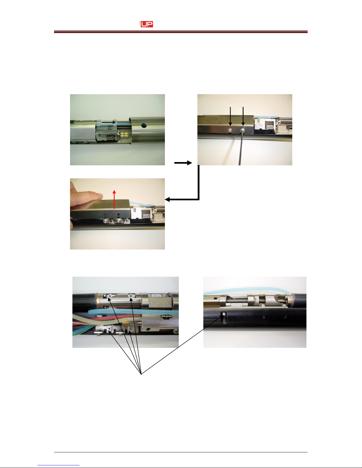
Service Manual JET3
94 Rev. 1.0
3. Remove print head cover. Release fixing bolts with allen key (SW 2,0 mm) by turning
about one rotation and remove the interior cover.
Attention:
It is not allowed to use a golf ball head allen keys,otherwise screw heads
could be damaged.
4. Remove the mounting plate (with drop production unit).
Remove the 5 retaining screws + the washers with an allen key (SW 2,0 mm)
Page 95
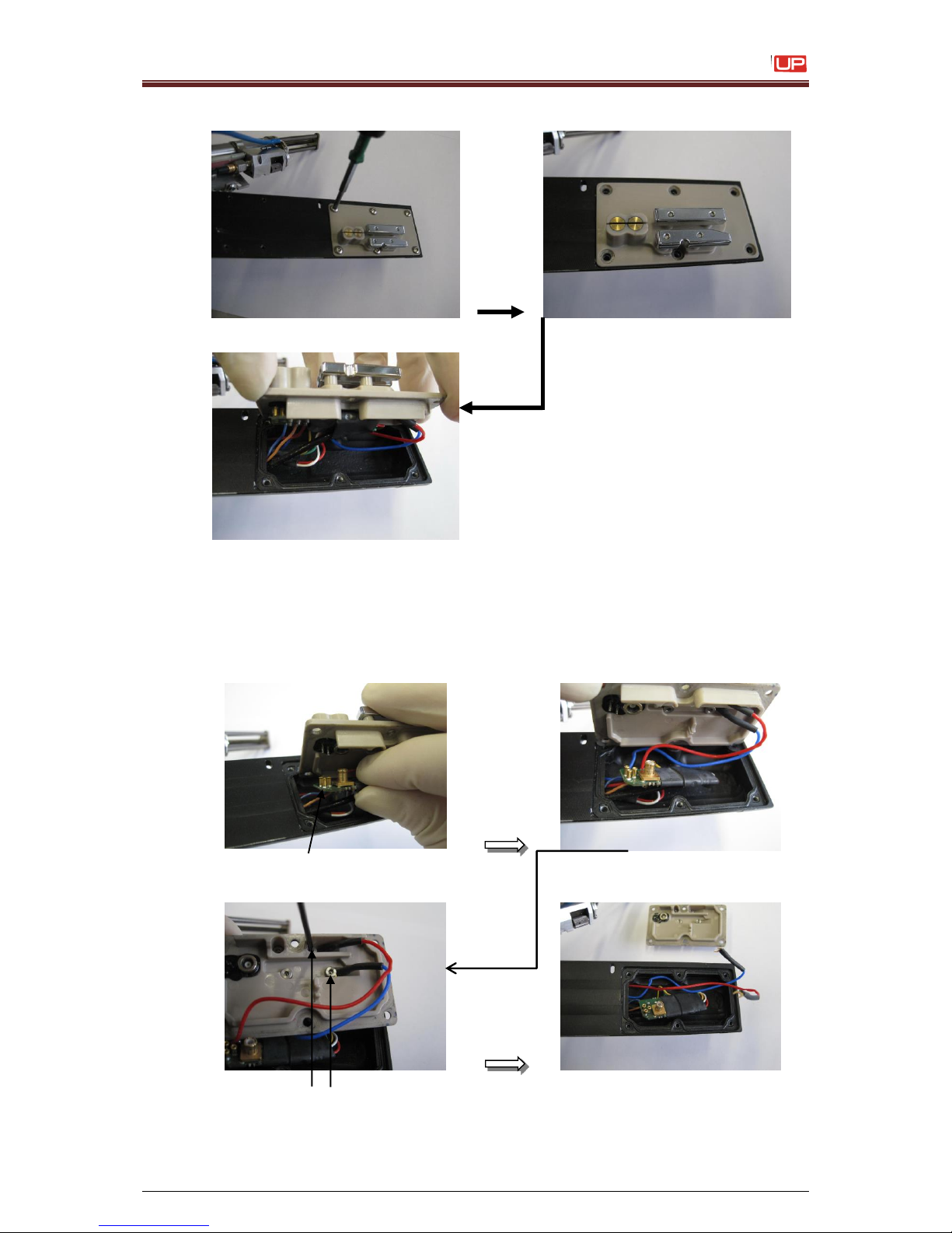
Service Manual JET3
Rev. 1.0 95
5. Remove the electrode block
Remove the 6 Torx screws with a Torx screwdriver (T8) and unplug the electrode
block from the print head!
6. Disconnect the electrode block from the print head electronic parts.
Remove the fixing screws from the HV-Cable with a Allen key (SW 1,5 mm)!
Unplug the charge board!
Page 96
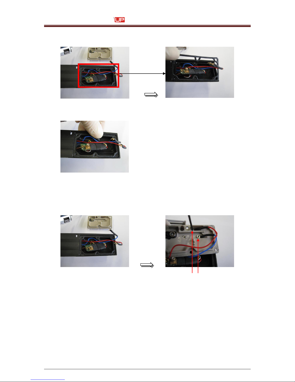
Service Manual JET3
96 Rev. 1.0
7. Remove the flat seal.
8. Insert the new flat seal and push it correctly down.
Attention:
You can insert the flat seal only in one
position!!!
If the position is not correctly,
it could be that the electrode block is not
leak-proof. Then solvent or ink can get
inside the print head and damaged them!
In this case you must change the
umbilical!
9. Fix the HV-Cable on the electrode block.
Attention:
Never mix up the red and blue cable!
Otherwise the drops will be not deflected correctly!
Fix the HV-Cable with the screws. For this you need an Allen key (SW 1,5 mm)!
Page 97
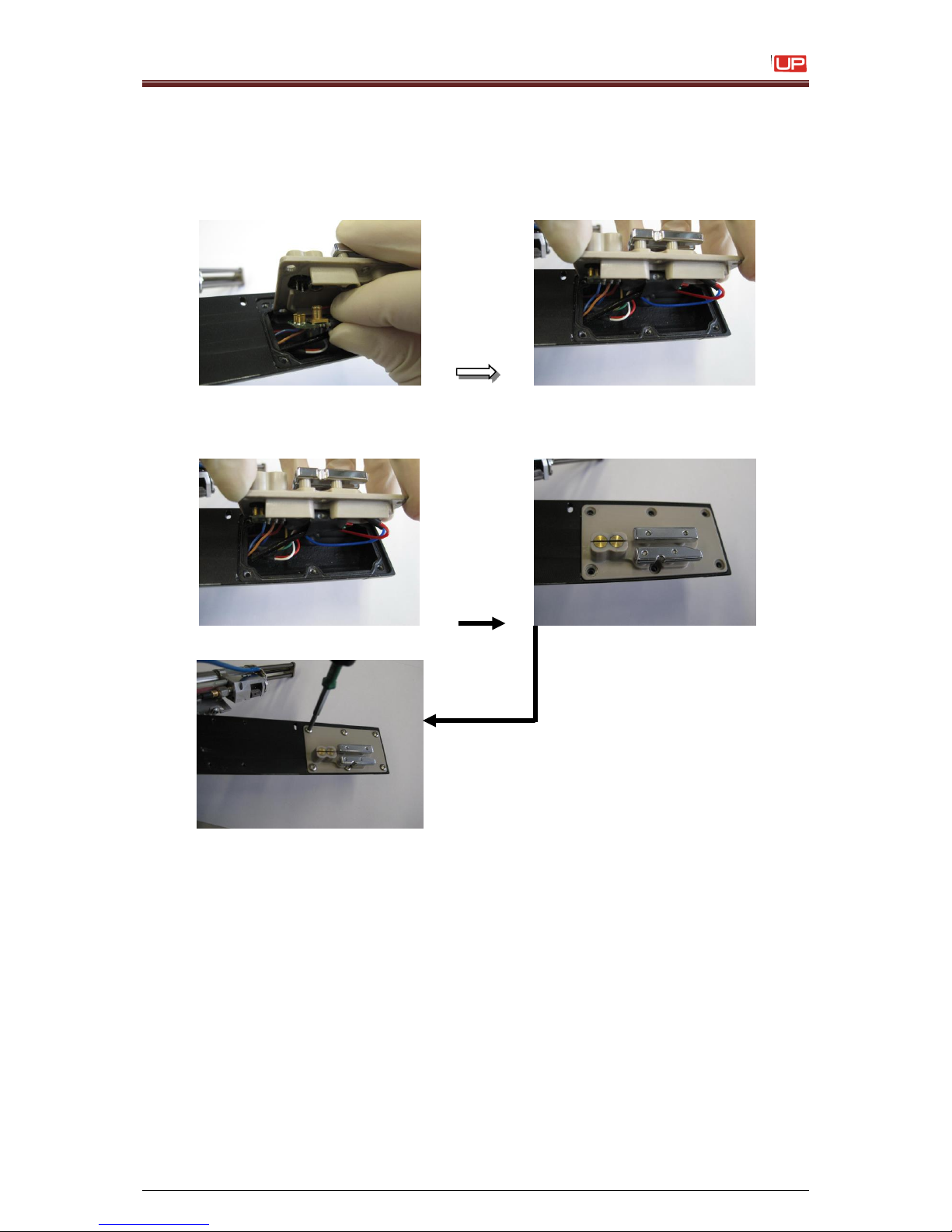
Service Manual JET3
Rev. 1.0 97
10. Connect the Charge-Board on the electrode block
Attention:
Take care that PINS not dismantle, when you connect the Charge-Board
on electrode block!
11. Put the electrode block in to the print head und fix it with screws.
Attention:
Take care, when you put in the electrode block in the print head, that no
cable jammed!
Also take care, that all 6 torx screws fixed with a torque allen key
(inside a blade for torx T8 and 0,18Nm)!
(You will find torque allen key 55-004557K + blade for torx T8 55-004559K in
our Spare Parts and Accessories Catalog).
Page 98
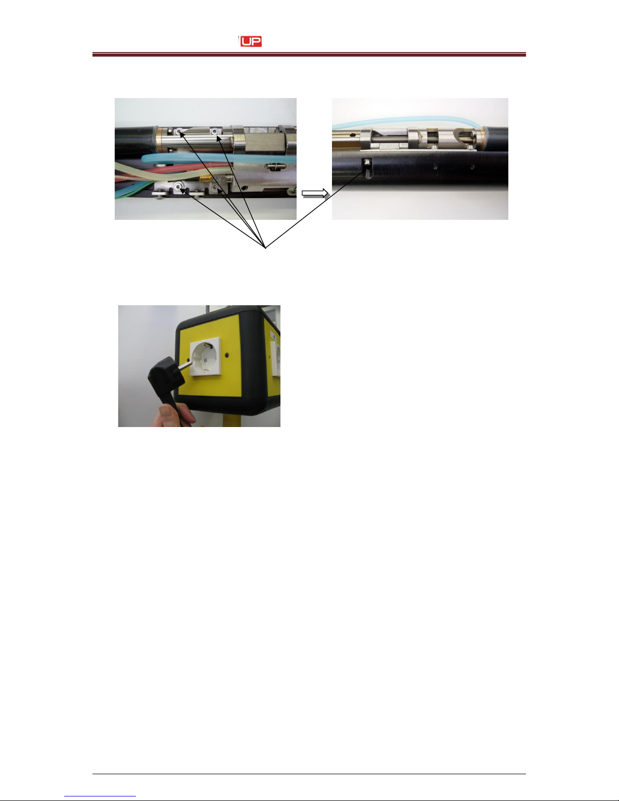
Service Manual JET3
98 Rev. 1.0
12. Fix the mounting plate (with drop production unit).
Fix all 5 screws + washers with an allen key (SW 1,5 mm) easily!
13. Plug in the main plug.
Attention:
Waiting for the booting process.
After this you can switch on the
printer!
Page 99
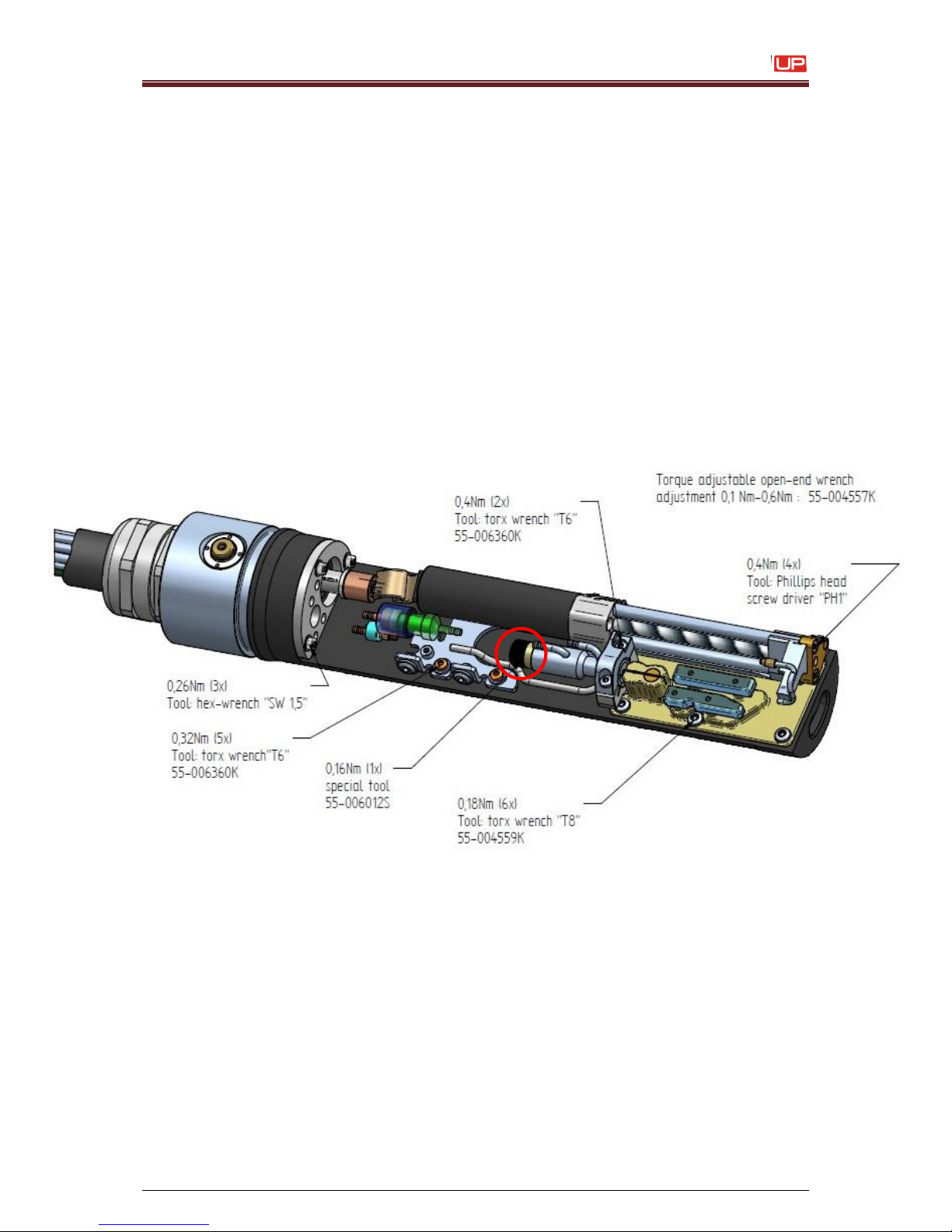
Service Manual JET3
Rev. 1.0 99
7.3 Documentations for
SK6
Torsional moments for SK6
Page 100
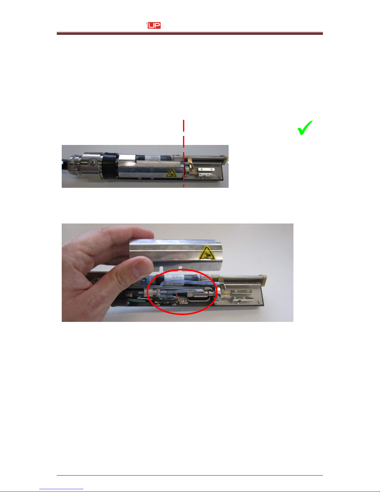
Service Manual JET3
100 Rev. 1.0
1) Cleaning of print head
We want to ask for your attention regarding the print head cleaning process:
Please be aware, that the print head has to be cleaned with solvent only in the front
area.
Behind the red line you must not clean with solvent.
Especially the area around the oscillator connection must not be flushed with solvent.
Otherwise solvent could penetrate inside the oscillator or the connector and could
cause damages or mal functions.
No cleaning necessary
=> No Solvent usage!!
Cleaning Area
=> Solvent can be used!!
 Loading...