

Page 1

Group 1 Table of contents Page 1
Release R1.03e LEIBINGER JET3
1.1 Table of contents
1.1 Table of contents........................................................................................ 1
1.2 Group directory........................................................................................... 8
1.3 Publisher....................................................................................................9
1.4 Introduction.............................................................................................. 11
1.5 Document information ............................................................................... 12
1.6 Guarantee ................................................................................................ 12
2. Safety .......................................................................................................... 13
2.1 Scope of risks .......................................................................................... 13
2.2 Safety instructions and recommendations .................................................... 13
2.3 Intended use ............................................................................................ 15
2.4 Safety sticker ........................................................................................... 16
2.5 Operating staff .........................................................................................17
2.6 Dangers due to electric energy.................................................................... 17
2.7 Personal protective equipment .................................................................... 17
2.8 Protective devices..................................................................................... 17
2.9 Safety measures at the place of installation.................................................. 18
2.10 Dangers through consumables .................................................................. 18
3. Accident prevention ....................................................................................... 20
3.1 Storage and handling (normal use)............................................................... 20
3.2 First aid measures ..................................................................................... 21
3.3 Fire fighting measures................................................................................ 21
3.4 Measures in the event of accidental release (spillage)..................................... 22
4. Technical data ............................................................................................... 23
4.1 Dimensions, weights, connections............................................................... 23
4.2 Electrical connection values........................................................................ 23
4.3 Ambient conditions ...................................................................................24
4.4 Interfaces, Inputs, Outputs......................................................................... 24
4.5 Performance parameter.............................................................................. 24
4.6 Fonts....................................................................................................... 25
4.7 Types of writing ....................................................................................... 25
4.8 Font combinations..................................................................................... 25
4.9 Function .................................................................................................. 25
4.10 Software................................................................................................ 26
5. Transport/Start up.......................................................................................... 27
Page 2

Group 1 Table of contents Page 2
Release R1.03e LEIBINGER JET3
5.1 Transport, storage, shipping ....................................................................... 27
5.2 Mounting ................................................................................................. 27
5.3 Installation ............................................................................................... 29
5.3.1 Mains supply ....................................................................................29
5.3.2 Grounding (Potential equalization) ........................................................ 30
5.3.3 Print head.........................................................................................32
5.4 Interfaces................................................................................................. 34
5.4.1 Ethernet-connection........................................................................... 34
5.4.2 Interface X5 (PrintGo) ........................................................................ 35
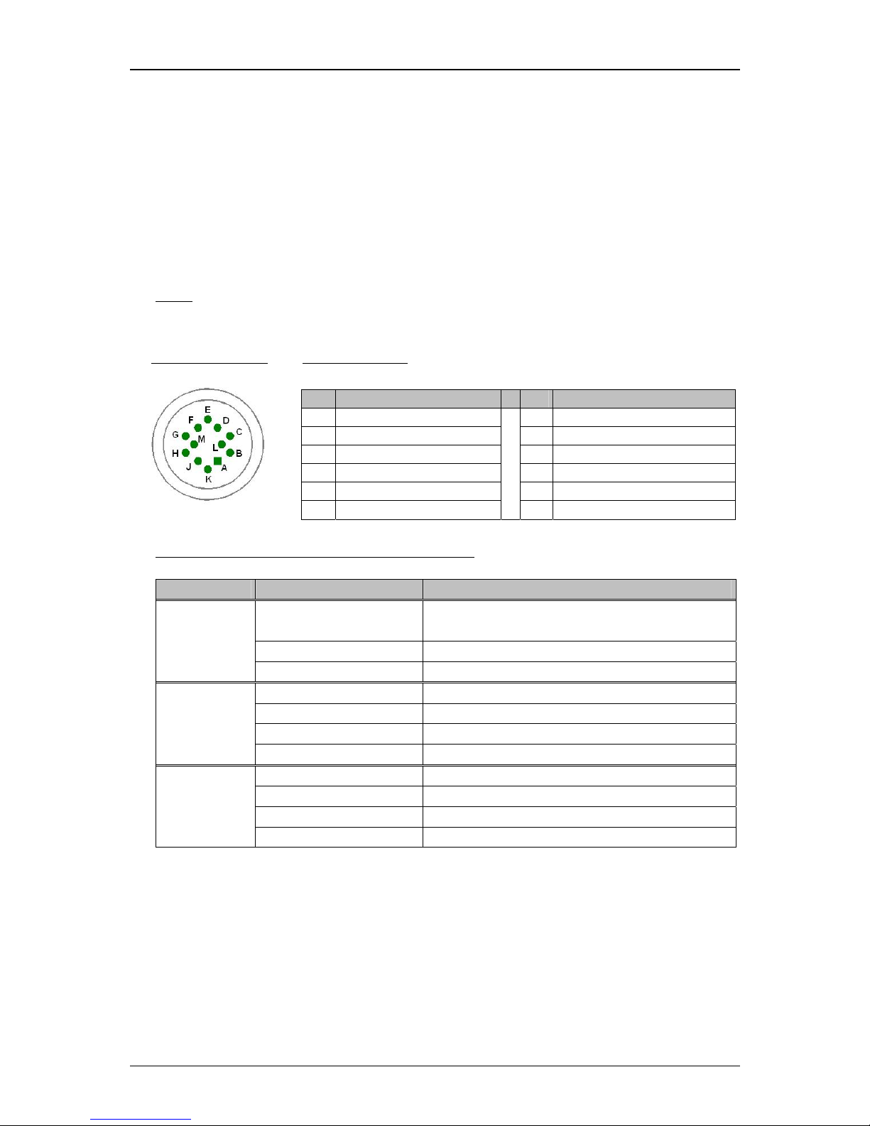
5.4.3 Interface X1 (Encoder) ....................................................................... 36
5.4.3.1 Description and configuration........................................................36
5.4.3.2 Mechanical installation ................................................................. 37
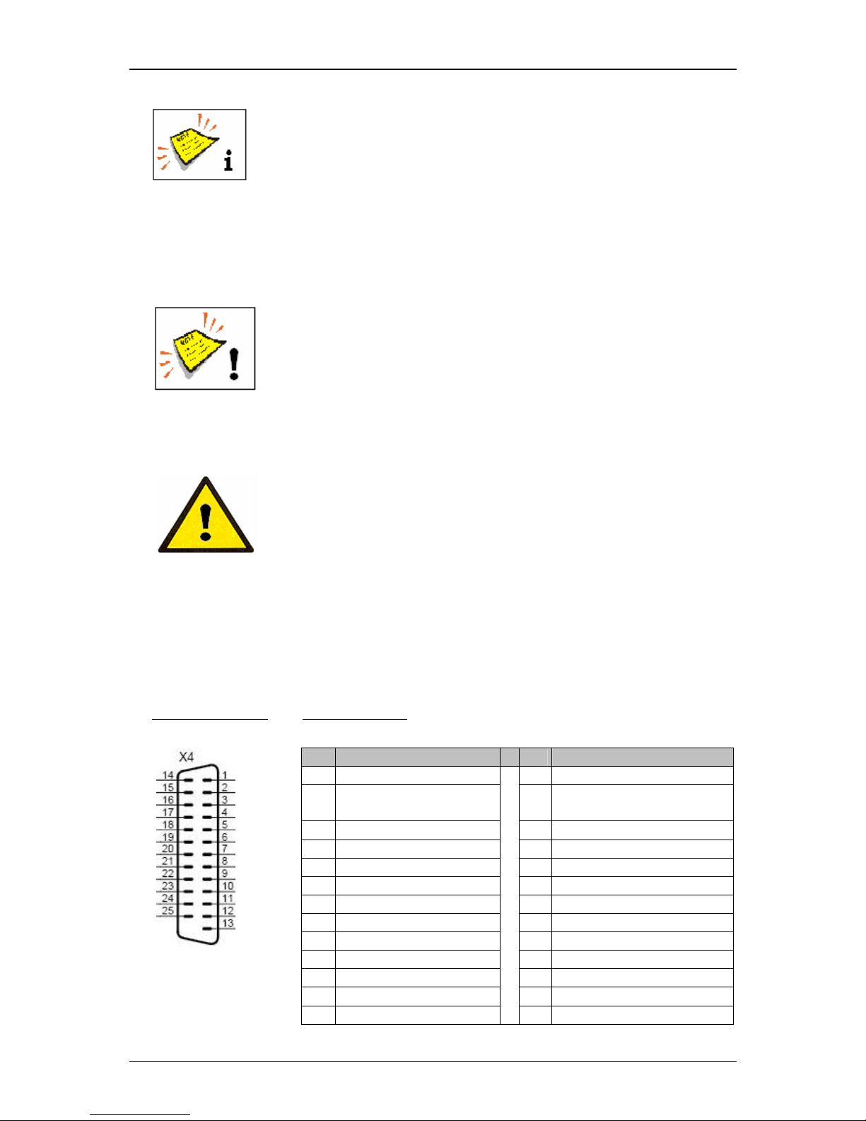
5.4.4 Interface X4 (Inputs).......................................................................... 37
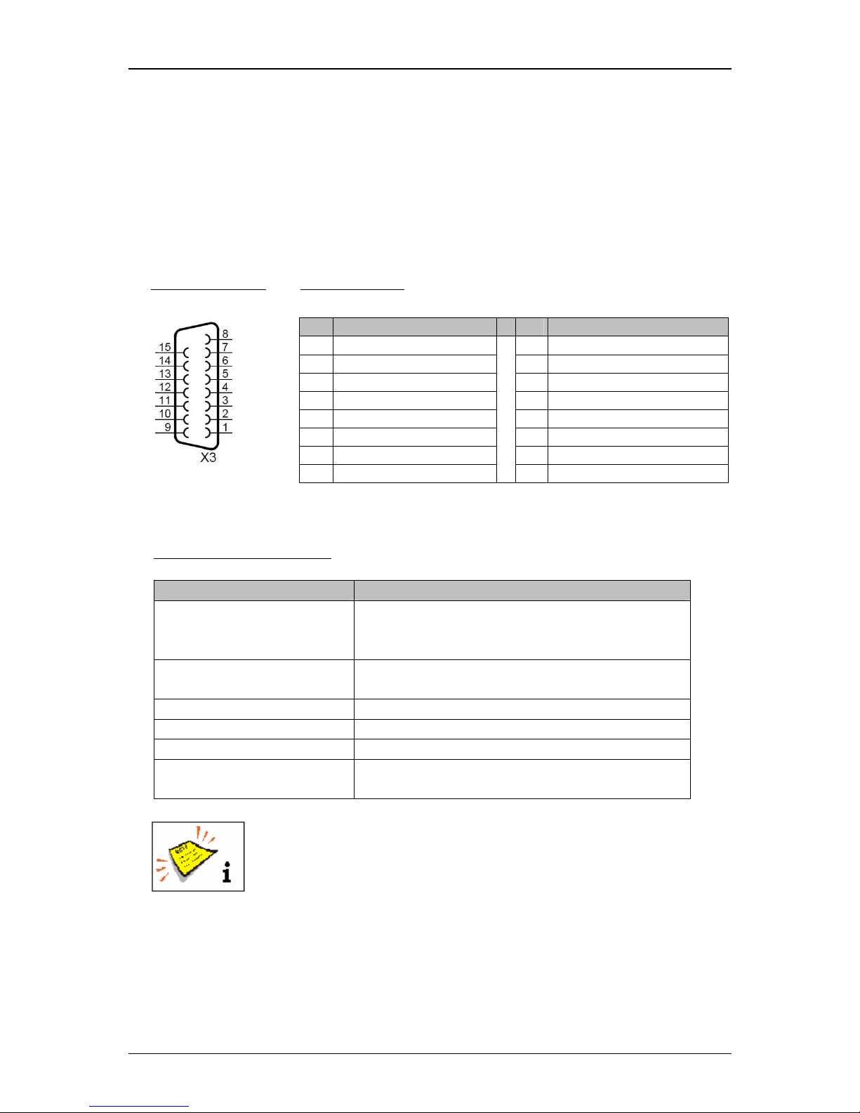
5.4.5 Interface X3 (Outputs) .......................................................................39
5.4.6 Interface X2 (Serial interface).............................................................. 40
5.4.7 USB-Connection ................................................................................ 40
6. Operation...................................................................................................... 41
6.1 Construction/Structure of the device ........................................................... 41
6.2 Functional principle ................................................................................... 42
6.2.1 Method of working ............................................................................ 42
6.2.2 Drop creation .................................................................................... 42
6.2.3 Drop charging ................................................................................... 43
6.2.4 Drop deflection .................................................................................43
6.2.5 Creation of a character....................................................................... 43
6.2.6 Summary of the individual procedures .................................................. 44
6.2.7 Example of use .................................................................................45
6.3 Essential operating- and information elements............................................... 46
6.3.1 Number blocks .................................................................................. 52
6.3.2 Keyboard fields .................................................................................53
6.4 Basic operating processes .......................................................................... 54
6.4.1 General ............................................................................................ 54
6.4.2 First initialization of the device ............................................................ 55
6.4.3 Switch on device............................................................................... 55
6.4.3.1 Switching on without password protection ..................................... 55
6.4.3.2 Switching on with password protetction......................................... 57
Page 3

Group 1 Table of contents Page 3
Release R1.03e LEIBINGER JET3
6.4.4 Reset product counter........................................................................59
6.4.5 Change product counter .....................................................................60
6.4.6 Switch off device .............................................................................. 62
6.5 Menu layout ............................................................................................. 63
6.6 Other settings and functions....................................................................... 64
6.6.1 Carry out Hardware Reset................................................................... 64
6.6.2 Interval operation (integrated clock timer) ............................................. 65
7. Data entry/Programming ................................................................................. 66
7.1 General.................................................................................................... 66
7.2 Job administration..................................................................................... 67
7.2.1 Create a new job ............................................................................... 68
7.2.2 Open job to edit ................................................................................ 69
7.2.3 Edit current job .................................................................................71
7.2.4 Load Job to print...............................................................................72
7.3 Settings................................................................................................... 73
7.3.1 Basic settings ...................................................................................74
7.3.1.1 Language and units...................................................................... 75
7.3.1.2 Date and time ............................................................................. 77
7.3.1.3 Interval operation (Set interval time)............................................... 79
7.3.1.4 Encoder interface ........................................................................81
7.3.1.5 Factory Settings .......................................................................... 82
7.3.2 Password settings and user authorizations ............................................ 84
7.3.2.1 Menu password settings............................................................... 84
7.3.2.1.1 Selection of user level.............................................................86
7.3.2.1.2 Definition of password ............................................................ 86
7.3.2.1.3 Definition of user rights...........................................................87
7.3.2.2 Lost password ............................................................................87
7.3.3 Password protection (Password query) ................................................. 88
7.4 Service functions ...................................................................................... 89
7.4.1 I/O Test............................................................................................ 90
7.4.2 Hydraulic-/Printhead – and special functions .........................................92
7.4.3 Printhead functions............................................................................94
7.4.3.1 Jet monitoring............................................................................. 94
7.4.3.2 Ink on/off ................................................................................... 95
7.4.3.3 Extern Ink on/off .........................................................................95
Page 4

Group 1 Table of contents Page 4
Release R1.03e LEIBINGER JET3
7.4.3.4 Piezo test and charge test............................................................. 96
7.4.3.5 Jet adjustment ............................................................................ 96
7.4.4 Special functions and tools ............................................................... 102
7.4.4.1 Constant bleed.......................................................................... 102
7.4.4.2 Mix only ink/sovent ................................................................... 104
7.4.4.3 Ignore all error messages and alarm messages............................... 105
7.4.5 Data logging (Log file) ...................................................................... 106
7.4.5.1 Select (call up) log file................................................................ 107
7.4.5.2 Save log file.............................................................................. 108
7.4.6 Service interval ...............................................................................109
7.5 Extra (Additional functions) ...................................................................... 110
7.5.1 Save counter states ......................................................................... 110
7.5.2 Test print .......................................................................................111
7.5.3 Product counter............................................................................... 113
7.5.3.1 Product counter settings............................................................. 114
7.5.3.2 Stop after x products (Pre-defined print stop) ................................ 116
7.5.3.3 Reset all job counters................................................................. 118
7.5.4 Login ............................................................................................. 119
7.5.4.1 Layout and call login-/logout dialog .............................................. 119
7.5.4.2 Login user or carry out user change ............................................. 121
7.5.4.3 Logout user .............................................................................. 122
7.5.5 Graphic editor ................................................................................. 123
7.5.5.1 Edit tools..................................................................................124
7.5.5.2 Organization tools...................................................................... 125
7.5.5.3 Drawing tools ...........................................................................126
7.5.5.4 Display tools............................................................................. 127
7.5.5.5 Load existing graphic ................................................................. 128
7.5.5.6 Save graphic/Save graphic as......................................................130
7.5.5.7 Carry out editor settings............................................................. 132
7.5.5.8 Create and process graphic elements ...........................................133
7.5.6 Font editor...................................................................................... 137
7.5.7 Explorer ......................................................................................... 139
7.5.7.1 Start explorer............................................................................ 139
7.5.7.2 Structure.................................................................................. 140
7.5.7.3 Explorer tools............................................................................ 141
Page 5

Group 1 Table of contents Page 5
Release R1.03e LEIBINGER JET3
7.5.7.4 Delete jobs ............................................................................... 143
7.5.8 Touch-Calibration ............................................................................ 144
7.6 Help ...................................................................................................... 146
7.6.1 Information..................................................................................... 146
7.6.1.1 Save info file............................................................................. 148
8. Job editor ................................................................................................... 149
8.1 Structure ............................................................................................... 149
8.2 Job editor tools ...................................................................................... 151
8.2.1 Edit tools........................................................................................ 151
8.2.2 Organization tools............................................................................ 152
8.2.3 Creation tools .................................................................................152
8.2.4 Formatting tool ............................................................................... 154
8.2.5 Parameter setting tools .................................................................... 155
8.2.6 Display tools................................................................................... 157
8.3 Job(editor)management ........................................................................... 158
8.3.1 Save job/Save job as........................................................................ 158
8.3.2 Load job to print.............................................................................. 160
8.3.3 Close job editor ............................................................................... 162
8.4 Object settings ....................................................................................... 163
8.4.1 Font selection ................................................................................. 164
8.4.2 Contrast value................................................................................. 165
8.4.3 Position settings.............................................................................. 166
8.4.4 Bold level (Bold text)........................................................................ 166
8.4.5 ICG-value ....................................................................................... 167
8.4.6 Orientation ..................................................................................... 167
8.4.7 Display settings............................................................................... 168
8.5 Parameter settings .................................................................................. 169
8.5.1 Print parameter ............................................................................... 169
8.5.1.1 PrintGo-delay ............................................................................ 169
8.5.1.2 PrintGo-distance........................................................................ 170
8.5.1.3 PrintGo-repetitions..................................................................... 171
8.5.1.4 PrintGo-holdoff distance ............................................................. 172
8.5.1.5 PrintGo-source .......................................................................... 173
8.5.1.6 PrintGo-Gate ............................................................................. 174
8.5.1.7 Monitoring functions .................................................................. 175
Page 6

Group 1 Table of contents Page 6
Release R1.03e LEIBINGER JET3
8.5.1.8 Drop flighttime .......................................................................... 176
8.5.2 Encoder parameter........................................................................... 176
8.5.2.1 Encoder source .........................................................................177
8.5.2.2 Internal speed ........................................................................... 178
8.5.2.3 Rotating direction ...................................................................... 178
8.5.2.4 Resolution ................................................................................ 178
8.5.2.5 Return stop............................................................................... 179
8.5.3 Font parameter values...................................................................... 179
8.5.3.1 Print height............................................................................... 179
8.5.3.2 Font width (Stroke distance) ....................................................... 180
8.5.3.3 Orientation ............................................................................... 180
8.5.3.4 Printing mode............................................................................ 181
8.5.4 Date changing parameter.................................................................. 183
8.6 Carry out settings of job editor ................................................................. 185
8.7 Printing elements .................................................................................... 188
8.7.1 Barcode.......................................................................................... 188
8.7.1.1 Barcode informations ................................................................. 188
8.7.1.2 Integration of counters ............................................................... 189
8.7.1.3 Carry out replacements .............................................................. 190
8.7.2 Date/time and expiry time.................................................................191
8.7.2.1 Insert date- and time specifications.............................................. 191
8.7.2.2 Carry out replacements .............................................................. 195
8.7.3 Counter..........................................................................................195
8.7.3.1 Counter parameter..................................................................... 196
8.7.3.1.1 Number of digits ..................................................................197
8.7.3.1.2 Start value .......................................................................... 197
8.7.3.1.3 Initialization value................................................................. 197
8.7.3.1.4 End value ............................................................................ 198
8.7.3.1.5 Leading zeros....................................................................... 198
8.7.3.1.6 Step width .......................................................................... 198
8.7.3.1.7 Repetitions .......................................................................... 198
8.7.3.1.8 Counting direction ................................................................ 199
8.7.3.1.9 End value control ................................................................. 199
8.7.3.1.10 Counter reset (methods)...................................................... 199
8.7.3.1.11 Counter increment (methods) ............................................... 200
Page 7

Group 1 Table of contents Page 7
Release R1.03e LEIBINGER JET3
8.7.3.2 Carry out replacements .............................................................. 200
8.7.4 Shift code ...................................................................................... 201
8.8 Replacements ......................................................................................... 203
8.8.1 Carry out replacements .................................................................... 204
9. Disturbances/Trouble shooting ....................................................................... 206
9.1 General.................................................................................................. 206
9.2 Display of device messages...................................................................... 206
9.3 Error messages ....................................................................................... 207
10. Equipping/Maintenance ............................................................................... 209
10.1 Equipping............................................................................................. 209
10.1.1 Refilling of ink and solvent .............................................................. 209
10.2 Service/Maintenance ............................................................................. 211
10.2.1 Daily servicing work....................................................................... 211
10.2.2 Weekly servicing work ...................................................................212
10.2.3 Anual servicing work...................................................................... 212
10.3 Cleaning .............................................................................................. 213
10.3.1 Cleaning the print head................................................................... 213
11. Taking out of operation/Dismantling ............................................................. 214
11.1 Taking out of operation.......................................................................... 214
11.2 Dismantling/Disposal ............................................................................. 214
12. Appendix .................................................................................................. 215
12.1 Circuit diagrams of the interfaces ............................................................ 215
12.2 Connection examples of the interfaces..................................................... 218
12.2.1 Interface X3 (Outputs) ................................................................... 218
12.2.2 Interface X4 (Inputs) ...................................................................... 219
12.2.2.1 Increment Counter Signal (PIN 2) ............................................... 219
12.2.3.2 Reset Counter Signal................................................................ 219
12.2.2.3 Jobselect Input........................................................................ 220
12.2.2.4 Inputs .................................................................................... 221
12.2.4.5 ON Input ................................................................................221
12.3 Technical drawings................................................................................ 222
12.3.1 Print head SK 4 ............................................................................. 222
12.3.2 Cabinet LJ3 .................................................................................. 223
List of keywords/Index ..................................................................................... 224
List of illustrations ........................................................................................... 230
Page 8

Group 1 Group directory Page 8
Release R1.03e LEIBINGER JET3
1.2 Group directory
The group directory serves as a guide through the device manual at hand to be able to
find specific subject areas quickly.
Group Directory Page
1 Overview .................................................................................... 1
Table of contents........................................................................ 1
Group directory ...........................................................................8
Publisher..................................................................................... 9
Introduction .............................................................................. 11
2 Safety ...................................................................................... 13
3 Accident prevention ................................................................... 20
4 Technical data ........................................................................... 23
5 Transport/start up ...................................................................... 27
6 Operation.................................................................................. 41
Construction/Structure ...............................................................41
Functional principle .................................................................... 42
7 Data entry................................................................................. 66
8 Job editor ............................................................................... 149
9 Disturbances/Trouble shooting ................................................... 206
10 Equipping/Maintenance ............................................................. 209
11 Taking out of operation/Dismantling............................................ 214
12 Appendix ................................................................................ 215
Circuit diagrams of the interfaces............................................... 215
Connection examples of the interfaces ....................................... 218
Technical drawings .................................................................. 222
List of keywords/Index ............................................................. 224
List of illustrations.................................................................... 230
Page 9

Group 1 Publisher Page 9
Release R1.03e LEIBINGER JET3
1.3 Publisher
For questions regarding the operation and running of the LEIBINGER JET3 as well as in
service case please contact the listed dealer address.
Dealer address
Paul Leibinger GmbH & Co. KG
Special factories for numbering machines
Daimlerstraße 14
D-78532 Tuttlingen
Federal Republic of Germany
Phone +49 74 61/92 86-0
Fax +49 74 61/92 86-1 99
E-mail: [email protected]
Service hotline phone +49 74 61/92 86-8 63
Service hotline fax 0 74 61/92 86-8 69
Service hotline e-mail: [email protected]
American Branch Office
Paul Leibinger
Numbering Machine LTD
2702-B Buell Drive
East Troy, WI 53120 USA
Tel.+01 262.642-4030
Fax.+01 262.642.4033
email: [email protected]
Page 10

Group 1 Publisher Page 10
Release R1.03e LEIBINGER JET3
We reserve all rights, in particular the right to translate, distribute and reproduce. No
part of this manual must be reproduced or distributed and stored through the use of
electronic data processing systems or made accessible to third parties in any form
(redrawn, photocopied, microfilmed or through any other process) without the written
consent of the publisher.
We reserve the right to make alterations to the scope of delivery at any time in the form
of technology, hardware, software as well as the corresponding materials (and manual
extracts) as a result of innovative further development of our devices.
Texts, illustrations and technical drawings have been compiled with the greatest of
care. Nevertheless errors cannot be excluded. Consequently no guarantee can be
assumed for the correctness of the content of this manual and no claims can be
asserted against Paul Leibinger GmbH & Co. KG.
We shall be grateful for information regarding possible printing errors as well as for
suggestions for the further optimisation of the device manual.
Authoritative for the scope of delivery is not the manual but rather the written order
confirmation.
Page 11
Group 1 Introduction Page 11
Release R1.03e LEIBINGER JET3
1.4 Introduction
We are pleased that you have decided in favour of a LEIBINGER JET3 device and
welcome you as one of our customers.
You now own a LEIBINGER JET3 device that has been developed and constructed on
the basis of many years of experience and using the latest Leibinger technology. This
results in a high degree of quality and the renowned Leibinger reliability.
This manual shows you the fundamental advantages of the Leibinger Jet system
manufactured by us, such as for example the fully automatic working, low maintenance
etc..
The manual must be read thoroughly prior to first start up in order to
ensure that no damage to the device and/or endangering of the
operating personnel results from a defective electrical connection
and/or from incorrect operation.
Please pay particular attention to the safety instructions of the groups
Safety instructions and accident prevention when handling
consumables (ink and solvent).
Our devices are subjected to a quality control in our plant prior to delivery. If despite
this the device or parts of it should be damaged or their function disturbed please advise
us of this as fast as possible.
It is only through the use of inks and solvents from Paul Leibinger GmbH & Co. KG that
optimum operating characteristics can be achieved. Should other inks and solvents be
used all guarantee claims will expire.
Product liability!
No alterations whatsoever must be carried out on the entire
LEIBINGER JET3 device. No liability will be accepted for damage or
dangers resulting from inadmissible alterations.
Caution – risk of explosion!
The device must not be operated in rooms where there is a risk of
explosion!
Page 12

Group 1 Introduction Page 12
Release R1.03e LEIBINGER JET3
1.5 Document information
The instruction Release R1.03e of 19
th
.January.2009 is valid for LEIBINGER JET3
machine with the given below serial number.
Seriennummer einkleben
Stick in serial number
1.6 Guarantee
The guarantee conditions for the LEIBINGER JET3 can be seen from the order
confirmation. The warranty presupposes that the device or the installation is operated
correctly in accordance with the available guarantee manual and any possible additional
manuals and descriptions prepared by us.
At this point we wish to make explicit reference to the fact that it is only when using
solvent and ink from Paul Leibinger GmbH & Co. KG that the optimum operating
characteristics can be achieved. In the event of use of other inks and solvents all
guarantee entitlements shall cease to apply.
Page 13
Group 2 Safety instructions Page 13
Release R1.03e LEIBINGER JET3
2. Safety
2.1 Scope of risks
The high performance printer LEIBINGER JET3 has been built in accordance with stateof-the-art standards and recognized safety requirements and has been equipped with
protective devices.
Operational and safety checks of the installation were carried out before it left the
factory. In case of improper handling or misuse, however, there are dangers for
the health of the operating staff
the high performance printer JET3 and other real assets of the plant operator
the efficient operation of the high performance printer
All persons entrusted with the putting into service, the operation, the maintenance and
the overhauling of the high performance printer must
have the necessary qualification and
strictly comply with this operating manual.
YOUR safety matters!
2.2 Safety instructions and recommendations
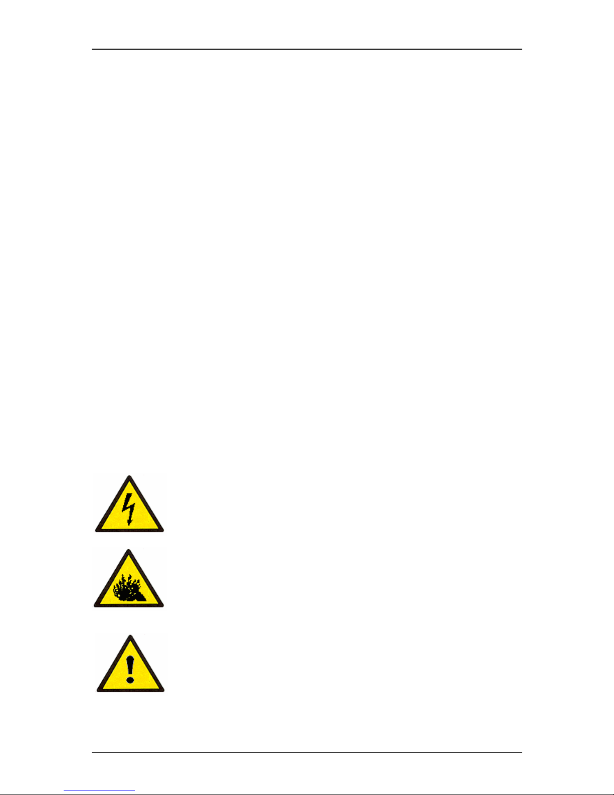
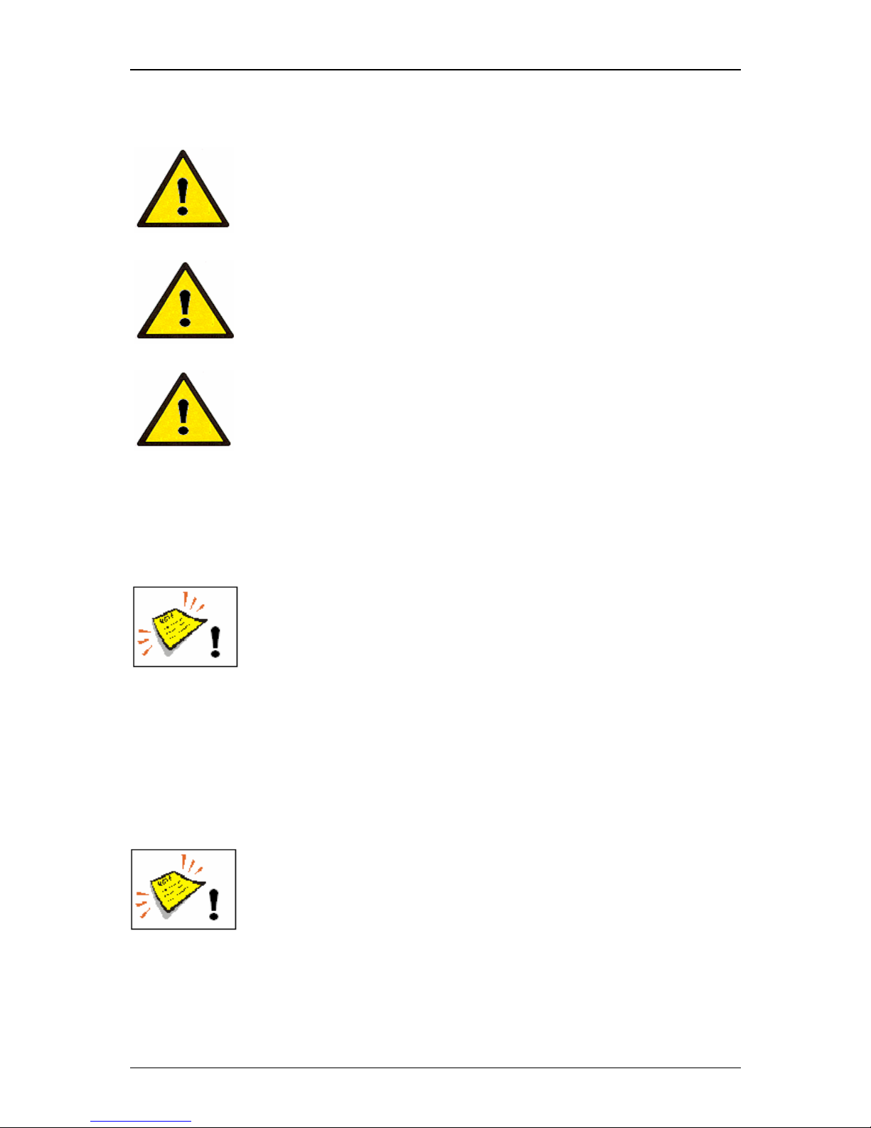
This operating manual use the following SYMBOLS with DANGER WARNINGS:
Indicates impending electrical danger!
Failure to observe this instruction can lead to serious injuries or to
death!
Indicates a dangerous situation through pressurised media!
Failure to observe this instruction can cause injuries!
Indicates a dangerous situation!
Failure to observe this instruction can lead to material damage or to
injuries!
Page 14
Group 2 Safety instructions Page 14
Release R1.03e LEIBINGER JET3
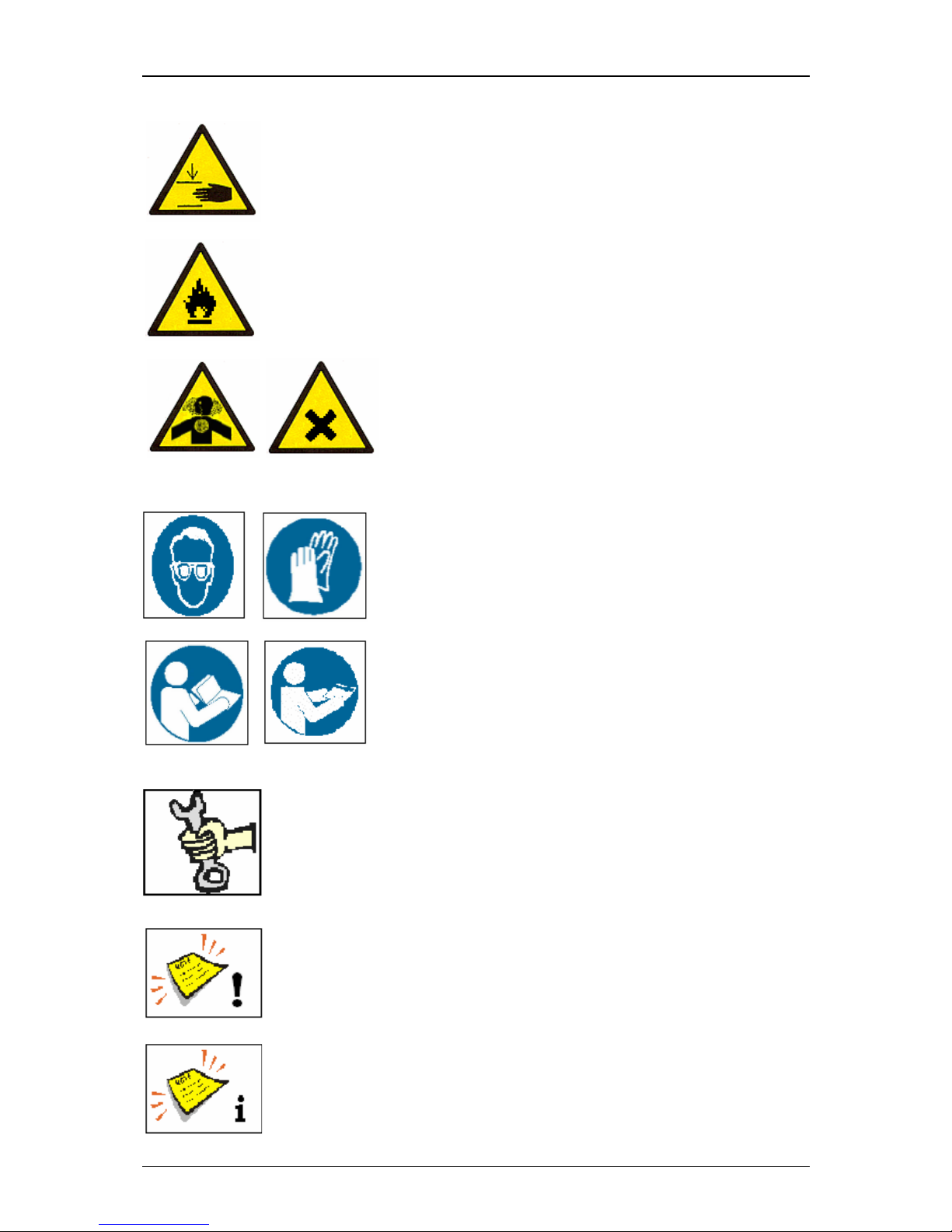
Indicates a dangerous situation!
Failure to observe this instruction can cause serious hand injuries!
Indicates a dangerous situation through flammable materials!
Failure to observe this instruction can lead to material damage, to
serious burns or to death!
Indicates a dangerous situation through irritating
materials!
Failure to observe this instruction can lead to poisoning
and to irritation of the eyes, the skin as well as of the
respiratory organs!
Indicates the necessity of personal protective clothing!
Sufficient protective equipment must be worn. Failure
to observe this instruction can lead to injury!
Indicates the necessity of observing the device manual
and other instructions!
Failure to observe this instruction can lead to material
damage, the loss of guarantee and to injury!
Indicates service activities!
This work must only be carried out by trained personnel or by
Leibinger service technicians!
Indicates important user information
for safe and effective working.
Indicates recommendations for use
and other useful pieces of information.
Page 15
Group 2 Safety instructions Page 15
Release R1.03e LEIBINGER JET3
2.3 Intended use
The high performance printer JET3 serves exclusively the contact-free marking,
inscribing and coding of surfaces using the continuous ink jet process.
The high performance printer can be used on the most varying materials (e.g. metal,
synthetic material, glass, paper, wood, pressed materials, rubber etc.) with both,
smooth as well as uneven, rough and stepped surfaces.
The intended use of this device also includes the observance of all
instructions in this manual.
Using the installation for other purposes is considered contrary to its
intended use!
For safety reasons conversions and alterations are only admissible
following consultation with the manufacturer. Repairs to the device
must only be carried out with original replacement parts.
The manufacturer shall not be liable for damage resulting from use for
other than the intended purpose or misuse.
Page 16
Group 2 Safety instructions Page 16
Release R1.03e LEIBINGER JET3
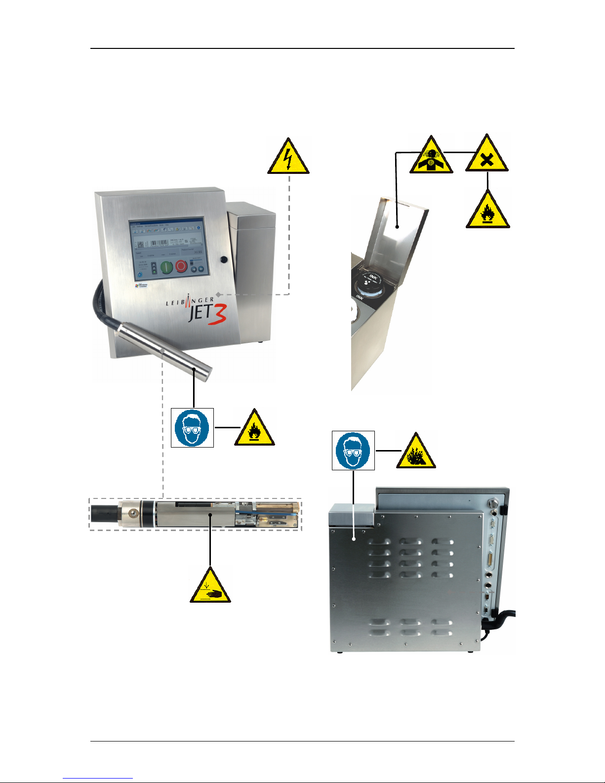
2.4 Safety sticker
Figure 1
Safety sticker
Page 17

Group 2 Safety instructions Page 17
Release R1.03e LEIBINGER JET3
2.5 Operating staff
Only trained personnel must operate the device. The personnel must have appropriate
training to enable them to be able to operate the JET3 high performance printer
professionally.
Within the working area of the LEIBINGER JET3 device the operator is responsible with
regard to third parties.
The operator must
put this operating manual at the operating staff’s disposal and
make sure that they have read and understood them.
2.6 Dangers due to electric energy
The electrical and electronic components of the high performance
printer are under voltage. The device must only be opened by trained
personnel or by Leibinger service technicians.
Prior to the opening of the device the device must be switched off
and the mains plug removed.
2.7 Personal protective equipment
Materials are processed in this device that cause irritations and which are under
pressure. In order to avoid injury and damage the personnel must wear the following
personal protective equipment during certain work procedures:
suitable work clothing
suitable eye protection
suitable hand protection
More detailed information can be found in the corresponding chapters of this manual as
well as possibly in information and data leaflets of consumables.
2.8 Protective devices
In an emergency the device is placed idle by removal of the mains plug.
Page 18
Group 2 Safety instructions Page 18
Release R1.03e LEIBINGER JET3
2.9 Safety measures at the place of installation
Mains connection!
The device has no mains switch and must only be connected to a plug
socket in the direct vicinity of the place of setting up!
Caution – risk of explosion!
The device must not be operated in rooms where there is a risk of
explosion!
Installation of the device
The device must be installed in a well ventilated room only and must
be kept away from any source of heat, flame or sparks, e.g. radiant
heater, etc.
A place of setting up must be selected with sufficient load bearing
capacity and stability. When setting up it must be observed that
sufficient movement space is available for the operating and service
personnel. Solvents are processed in the device, sufficient room
ventilation must be ensured!
Prior to assembly the place of setting up must be cleaned of dirt and
contamination (residue of lubricants etc.). The working place
surroundings should be kept clean at all times in order to ensure
unrestricted access to the LEIBINGER-JET3 device.
2.10 Dangers through consumables
Inks are coloured liquids on a solvent basis. The safety instructions on the containers of
the consumables as well as the instructions in the group Accident prevention must be
especially adhered to in order to exclude dangers for persons and the surroundings.
Further instructions can be found in the Safety Data Sheets.
When handling consumables (inks/solvents) the danger instructions
and safety advice on the containers (transport, storage, distribution
and correct disposal) must be observed!
Page 19

Group 2 Safety instructions Page 19
Release R1.03e LEIBINGER JET3
In addition we recommend observance of the safety information
leaflets of the inks and solvents used.
In the following you will find examples for the marking of inks and solvents.
Figure 2
Examples:
Labels for the marking of inks and solvents.
Page 20

Group 3 Accident prevention Page 20
Release R1.03e LEIBINGER JET3
3. Accident prevention
The following presentation shows the measures in the event of an accident with ink and
solvent with the danger marking,
slightly ignitable
irritates the eyes and the respiratory organs.
3.1 Storage and handling (normal use)
GENERAL These products must only used at points that are free from
open flames and other ignition sources. Do not use pressure for
emptying –
the container is not a pressure vessel. Good
household practice and regular, safe removal of the waste
materials restrict the danger of self-ignition and other risks of
fire to a minimum. The product can charge statically. When
pouring from one container to another use a mass lead. The
workers must wear anti-static shoes and clothing and the floors
must be conductive.
STORAGE Observe the marking information. Store at 5 to 25°C in a
warm, well ventilated location at a safe distance from heat and
ignition sources and direct sunlight.
Do not smoke!
Do not grant access to unauthorised persons.
Open containers must be properly closed and stored upright in
order to avoid leakage.
Smoking, eating and drinking must be forbidden in the storage
and working areas. Always keep in containers from the same
material as the delivery containers.
HANDLING The development of combustible or explosive vapour
concentrations must be prevented and vapour concentrations
avoided that are above the threshold values of the employers
liability insurance association. Keep containers closed tightly.
Keep sources of heat and sparks as well as open flames well
away.
Use only spark-free tools. Electrical devices must be protected
in accordance with the corresponding standard.
Avoid contact with the skin and eyes. Do not inhale vapours
and spray mist.
Page 21

Group 3 Accident prevention Page 21
Release R1.03e LEIBINGER JET3
3.2 First aid measures
EYES Contact lenses must be removed. Rinse thoroughly with pure,
fresh water for at least 10 minutes, keep eyelids spread and
call a doctor.
SKIN Remove contaminated clothes. Wash skin thoroughly with soap
and water or with a branded skin cleansing agent. DO NOT use
solvents or thinners.
INHALING Take patient into the
fresh air and keep warm and calm. In the
event of irregular breathing or of breath being missed
resuscitate artificially. Do not give anything orally, place
unconscious patients on their side and call a doctor.
MISCELLANEOUS In case of doubt or with persistent symptoms call a doctor.
Never give anything orally to unconscious patients.
3.3 Fire fighting measures
EXTINGUISHING
AGENTS
Recommended
: Alcohol-resistant foam, spray water/mist, CO2
or powder
DO NOT use water jets. Cool closed containers exposed to the
fire with spray water.
RISK OF FIRE AND
EXPLOSION
As the product contains combustible organic constituents, a
thick, black smoke develops in the event of fire that contains
dangerous combustion products. Decomposition products can
constitute a danger to health. Extinguishing waste water must
not enter the waste water channels or waters.
PROTECTIVE
MEASURES
If necessary suitable, independent breathing apparatus is
required.
Page 22

Group 3 Accident prevention Page 22
Release R1.03e LEIBINGER JET3
3.4 Measures in the event of accidental release (spillage)
PRECAUTIONARY
MEASURES
Switch off sources of ignition and ventilate room. Keep
personnel that is not absolutely necessary away. Do not inhale
any vapour. Observe the protective measures listed.
ENVIRONMENTAL
PROTECTION
MEASURES
DO NOT allow to enter waste water channels or waters.
Should the product enter waste water channels or the drainage
system the local water supply authority must be informed
immediately. In the event of contamination of streams, rivers or
lakes inform the national water authorities. Vapour is heavier
than air and can spread out on the ground. In combination with
air it can form an explosive mixture.
RESTORATION Restrict and suck up spilled substances with a non-combustible
absorbent material (e.g. sand, earth, vermiculite, infusorial
earth) and collect in a suitable container for removal. Preferably
clean areas with spilled substances with a detergent. Avoid
solvents.
Page 23
Group 4 Technical data Page 23
Release R1.03e LEIBINGER JET3
4. Technical data
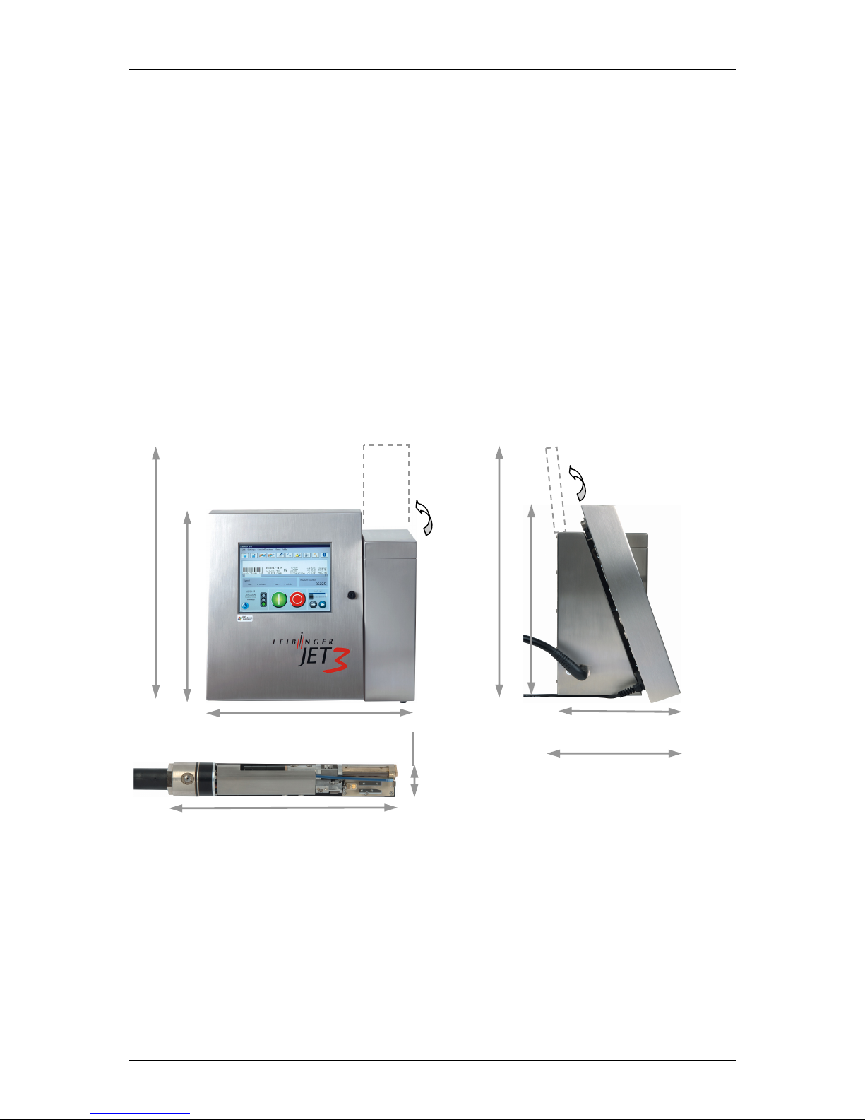
4.1 Dimensions, weights, connections
Cabinet : Stainless steel
Width 486 mm, depth 286 mm, height 446 mm
Weight: 20,5 kg
Print head: Stainless steel cabinet
Length (total) 265 mm, diameter 43 mm,
Length of the print head lead 3 m, as option 6 and 10 m available
Weight: 1,5 kg
Any fitting position, also for overhead conveyor applications
Figure 3
Dimensions
Protection class: IP 54 (as option: IP 65)
4.2 Electrical connection values
Input voltage (voltage range): 100 - 240 V AC ,50-60 Hz
Power consumption: max. 40 VA
∅
43
mm
286 mm
344 mm
265
mm
486 mm
446 mm
565 mm
446 mm
565 mm
Page 24

Group 4 Technical data Page 24
Release R1.03e LEIBINGER JET3
4.3 Ambient conditions
Temperature range: + 5° C to + 45° C
(no rapid change of temperature)
Relative humidity: max. 90 % relative humidity (non-condensating)
4.4 Interfaces, Inputs, Outputs
Product sensor input: NPN/PNP 24V
Incremental encoder input: TTL 5V, HTL 24V, RS422 5V
Inputs: 6 digitals, free selectable
10 inputs for ext. job selection
Outputs: 8 digitals, e.g. for alarm, re-filling, etc.
Interfaces: Ethernet (Industry standard M12D)
Serial Interface (V24/RS232) up to 115.200 Baud
USB
Others: Remote maintenance via RS232
4.5 Performance parameter
Printing capacity:
Character height: approx.
min.: 0,8 mm
max.:16 mm
Depending on font, distance of head, nozzle diameter,
ink, product surface and type of print head
Up to 3200 characters/sec.
Printing speed: Up to 6,6 m/sec (10 cpi)
Page 25

Group 4 Technical data Page 25
Release R1.03e LEIBINGER JET3
4.6 Fonts All fonts can be combined arbitrarily
Printing of 1-5 lines
Tower print
Capitals and lower case letters, umlaut, special
characters
Fonts 5x5 up to 32x24
Multistage contrast- and bold text
All common Barcodes (Barcode 39, Code 128C,
Postnet etc.) and Data-Matrix-Codes (ECC 200), GS1Data-Matrix (EAN/ECC)
4.7 Types of writing Double distance
Texts backwards
Symbols mirror-inverted
Symbols mirror-inverted and upside down
Symbols mirror-inverted, upside down and text
backwards
Alternating readable font, reverse, bold text, inverse
4.8 Font combinations All fonts can be presented in one writing in the
requested matrix.
4.9 Function Full automatic function by:
The automatic nozzle seal guarantees that the print
head is ready to print immediately after starting.
Automatic, electronic drop control for
compensation of changing ambient- and operating
temperatures
Automatic viscosity control
Splash-free re-filling of ink and solvent during the
printing operation
Page 26

Group 4 Technical data Page 26
Release R1.03e LEIBINGER JET3
4.10 Software Functions:
Selectable print delay or print repetition
Any combination of constant and variable texts within a
printing line
10 individually programmable counters
Current date- and time printing, original date
Free programmable graphics/logos, creatable in the integrated
editor
Jobeditor allows the saving and calling of texts and all printing
relevant parameters
Programmable batch processing of jobs and bonding of several
jobs
„External-Text“ function
Variable text (Data base processing)
Replacements: all date-, time-
and counter functions are
codable by replacements
Shift operation
Page 27
Group 5 Transport/Start up Page 27
Release R1.03e LEIBINGER JET3
5. Transport/Start up (Putting into service)
5.1 Transport, storage, shipping
In order to avoid damage during transport the following instructions must be observed.
The LEIBINGER JET3 must only be transported in a standing position. It is packed in a
cardboard box with special polystyrene inserts for safe dispatch during delivery.
Transport of the device must only be made in this packing in order to avoid damage.
The printer should be only transported in an empty condition
! A special
draining routine (“ServiceFunctions X Hydraulic X Special Functions/
Tools X Drain Routine“) is available for the draining of the device.
You will find further information in the group Data input/Programming
in the chapter Draining routine!
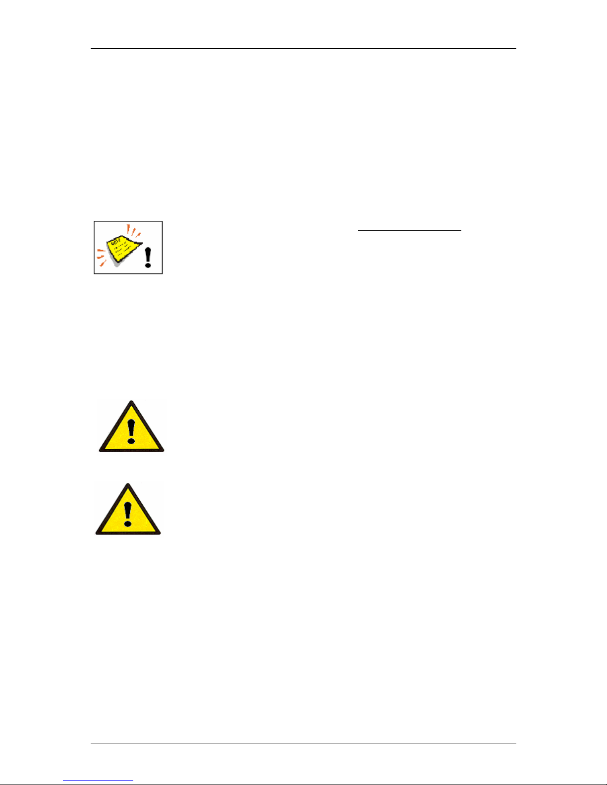
Note! Storage temperatures below +5°C and above +50°C as well as storage at
outside are not admissible and can lead to damage!
5.2 Mounting
Caution – risk of explosion!
The device must not be operated in rooms where there is a risk of
explosion!
Installation of the device
The device must be installed in a well ventilated room only and must
be kept away from any source of heat, flame or sparks, e.g. radiant
heater, etc..
Check device for damage! When determining a suitable place of setting up, the
necessary additional space requirement for the movement room of the operating and
service personnel must be taken into consideration. Solvents are processed in the
device, adequate room ventilation must be ensured!
Page 28
Group 5 Transport/Start up Page 28
Release R1.03e LEIBINGER JET3
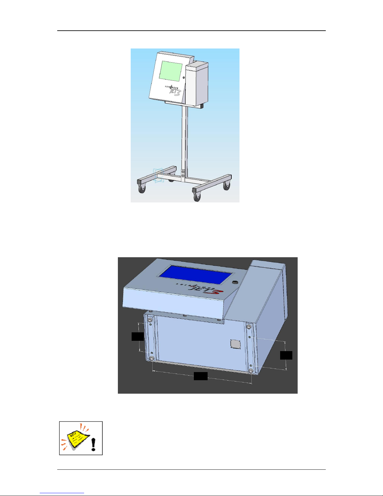
Figure 4
Movable underframe
for JET3:
For this it is expedient to place the device on a device support.
The device has four fastening possibilities for secure seting up and should be screw
connected at the place of setting up.
Figure 5
Fastening posibilities
A place of setting up with sufficient load bearing capacity and stability
must be chosen. Prior to assembly the place of setting up must be
cleaned of dirt and contamination (residue of lubricants etc.) .
120
120
355
Page 29
Group 5 Transport/Start up Page 29
Release R1.03e LEIBINGER JET3
5.3 Installation
For adaption to the production line several works have to be carried out and operating
parameters have to be set before start of operation.
5.3.1 Mains supply
Mains supply!
The device does not have a mains switch and should be only
connected to a socket close to the installation location!
The LEIBINGER JET3 should be connected to AC voltage 100 - 240 V AC, 50 –
60
Hz with an appropriate plug. The socket should be provided with a clear designation
(e.g.: JET3).
After connecting to the mains power supply the initialization of the device will be
carried out automatically. After this process the JET3 is ready for operation.
You will find further information regarding the initialization in the
Chapter Initialization of device!
Page 30
Group 5 Transport/Start up Page 30
Release R1.03e LEIBINGER JET3
5.3.2 Grounding (Potential equalization)
Grounding (Potential equalization)!
In case of a non existing grounding or that the grounding of the
printer is not carried out properly, this could cause serious injury or
death and it can also cause malfunctions or damages at the printer!
These dangers or demolitions can happen for example because of
electrostatic discharge (ESD) or potential difference.
Specially for countries without existing protected earth connection, there is a
special grounding point located at the side of the printer.
This threaded socket must be connected to ground if there is no ground pin in the
mains socket/plug.
The threaded case is sealed inwards and thus IP 65 conform. With a screw and a
ring terminal (cable lug) the grounding can be fixed easily.
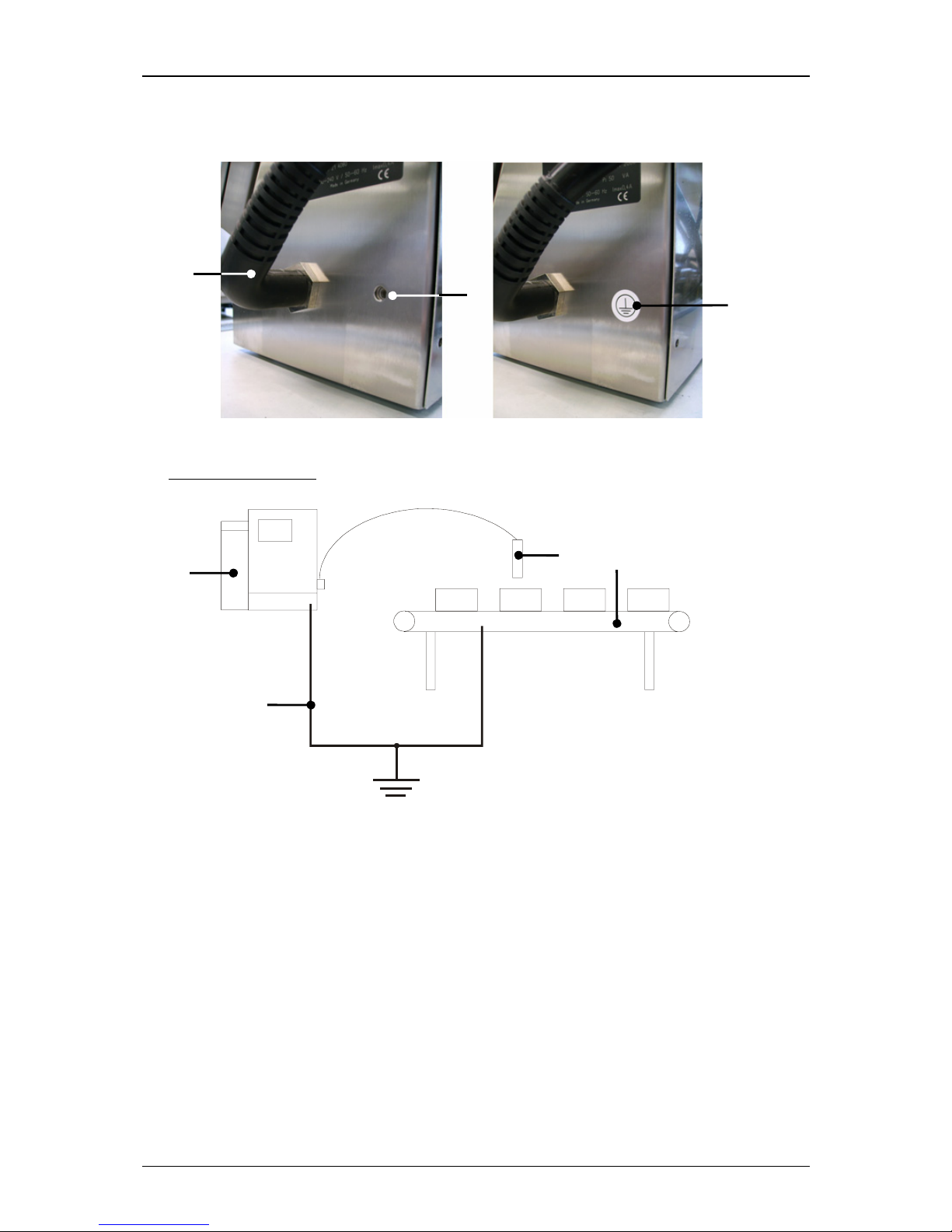
Please note, that the grounding point (7) is hidden behind the round
grounding-symbol-label (6) on the lower left hand side of the cabinet
of the printer.
Grounding instructions
A separate grounding line (min. cable cross-section 2,00 mm
2
) to the printer
cabinet must be installed before
the print head is mounted in the installation and
before the printer is plugged to the power supply.
The connection must be carried with a solid bonding that corresponds with
existing guidelines.
Annotation:
A suitable grounding cable is available optionally (accessories).
The installation (machine) and the printer must have the same potential/ground.
The printer must be always be switched off and the mains plug
must be always unplugged if you plug and/or unplug any
connectors!
Page 31
Group 5 Transport/Start up Page 31
Release R1.03e LEIBINGER JET3
Figure 6
Grounding scematic and gounding point
1 – Printer cabinet 4 – Grounding line 7 – Grounding symbol-label
2 – Installation (machine) 5 – Umbilical
3 – Print head 6 – Grounding point (M6)
5
6
7
Grounding scematic
ground / earth
4
1
3
2
Page 32
Group 5 Transport/Start up Page 32
Release R1.03e LEIBINGER JET3
5.3.3 Print head
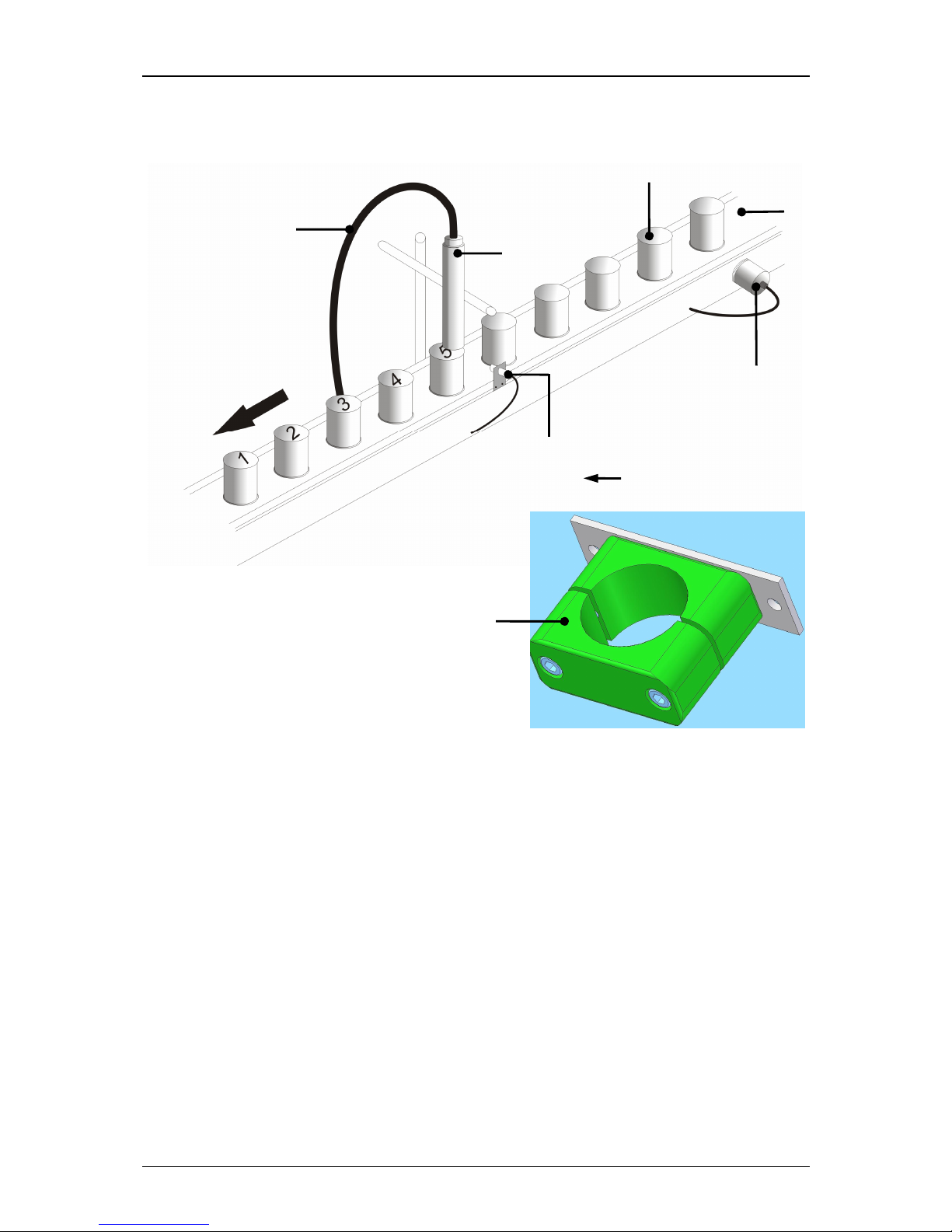
The print head should be mounted to the printed product that the notch in the head
cover is placed vertical to the moving direction of the product. It can be installed
horizontal, vertical, from the top or from the bottom.
For installation from the bottom it has to be prevented that dirt can enter in the
print head. For this a head ventilation is required which can be purchased optionally.
The print head mounting should be carried out that a fast separation of the print
head from the device for cleaning purposes is possible.
The print head should be attachted vibration-free. The hose
connection of the print head should not be smaller as a radius of
R60 statistically and dynamically not below R100!
The distance of the print head to the product depends on the required character
height. As smaller the required character height, as smaller the distance of the print
head to the product (smaller distances produce better type quality)
Note:
In general a distance of round about 8-10mm is recommended.
For applications with extreme small or large character heights a micro-
and
macro print head are available optionally.
Installation of print head
During an installation of a device in a production line, the operating
staff should be not endagered. Due to moving products under the
print head danger of bruisings and shearing can be caused. The
regulations of the machinery directives should be observed!
Page 33
Group 5 Transport/Start up Page 33
Release R1.03e LEIBINGER JET3
Figure 7
Print head installation (Example)
1 – Product 4 – Sensor 6 – Umbilical (Hose connection)
2 – Conveyor belt 5 – Print head 7 – Print head adapter
3 – Encoder (accessories)
3
5
4 2
1
= Conveying direction
6
7
Page 34
Group 5 Transport/Start up Page 34
Release R1.03e LEIBINGER JET3
5.4 Interfaces
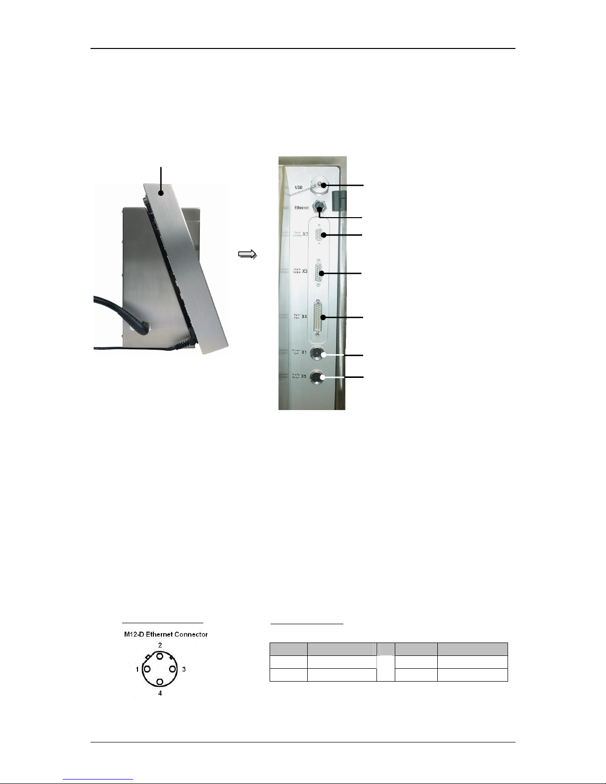
The following interfaces are available on the rear side of the electronics cabinet.
Figure 8
Interfaces
1 – Electronic cabinet 5 – Interface X3 – digital outputs
2 – Interface X5 – PrintGo 6 – Interface X2 – Serial Interface
3 – Interface X1 – Encoder 7 – Ethernet-connection
4 – Interface X4 – digital inputs 8 – USB connection
5.4.1 Ethernet-connection
The Ethernet-connection is implemented with a sturdy M12D coded socket and is
designed for high transfer rates and long cable lengths. It provides the networking
of several devices in multi-head applications. The data exchange happens via the
„LEIBINGER JET3-interface protocol“.
1
6
4
2
7
3
5
8
Pin No Designation Pin No. Designation
1
Tx + 3 Tx -
2
Rx +
4 Rx -
Plug assignment:
Pin connection:
Page 35
Group 5 Transport/Start up Page 35
Release R1.03e LEIBINGER JET3
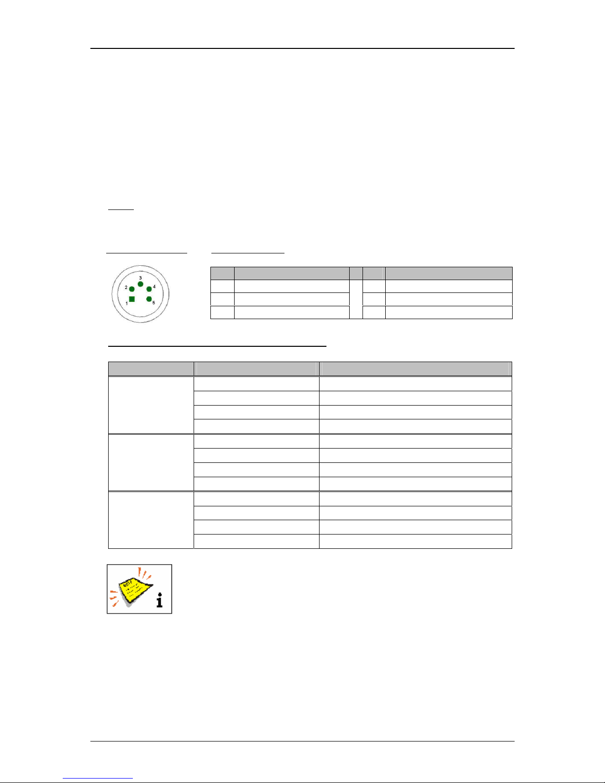
5.4.2 Interface X5 (PrintGo)
The interface “X5” provides the connection of an external PrintGo-signal. All
common product detectors (e.g. light barrier, product sensor ect.), 24V NPN-
as
well as 24V PNP-switching can be connected.
Regarding the software you can
select additionally if the positive edge or the
negative edge should be used for the release of the print out.
Note:
To inform the JET3 when a print text should be printed, you require a so-
called Print-Go signal.
Basic data/Recommended working conditions:
Signal Parameter Value
Input level High 15 up to 30V
Input level Low -3,5V up to 3,5V (or high resistance)
Minimum pulse duration 100µS
PrintGo
Input resistance 6,8 kOhm
Input level High 20 up to 28V (or high resistance)
Input level Low -6V up to 9V
Minimum pulse duration 100µS
/PrintGo
Input resistance 6,8kOhm
Input level High 15 up to 30V
Input level Low -3,5V up to 3,5V (or high resistance)
Minimum pulse duration 100µS
PrintGo Gate
Input resistance 6,8 kOhm
You will find a circuit diagram of the interface in the appendix of this
manual!
(1)
All 24V inputs which are designated with (1) are protected by a self-reset fuse with 700 mA.
Pin Designation Pin Designation
1 +24 V
(1)
4 PrintGo
2 /PrintGo 5 PrintGo_Gate
3 GND
Plug assignment:
Pin connection:
Page 36
Group 5 Transport/Start up Page 36
Release R1.03e LEIBINGER JET3
5.4.3 Interface X1 (Encoder)
5.4.3.1 Description and configuration
The interface “X1” provides the connection of a shaft encoder.
Due to the input for which you can set the software individually, the encoders can
be connected according to different norms without an additional converter.
Note:
For variable product speed you have to use a shaft encoder to synchronize
the printing speed or to control the constant font width.
Basic data /Recommended working conditions:
Signal type Parameter Value
Input level
Difference input ≥ +/-200mV
Input voltage range: -0,3 bis 5,5V
Max. frequency 10 MHz
RS422
Terminating resistor 100 Ohm
Input level High 2,4V up to 5,5V
Input level Low -0,5V up to 0,7V
Max. frequency 500 kHz
TTL
Input resistance 1 MOhm
Input level High 12 up to 28V
Input level Low -0,5 up to 3,5V
Max. frequency 500 kHz
HTL
Input resistance 4 kOhm
(1)
All 24V inputs which are designated with (1) are protected by a self-reset fuse with 700 mA.
Pin Designation Pin Designation
A +5 V (max. 400 mA) G Encoder port /B RS422
B GND H Encoder port A TTL (5V)
C +24 V
(1)
J Encoder port B TTL (5V)
D Encoder_port A RS422 K Encoder port A HTL (24V)
E Encoder port /A RS422 L Encoder port B HTL (24V)
F Encoder port B RS422
M PowerOn Option
Plug assignment:
Pin connection:
Page 37
Group 5 Transport/Start up Page 37
Release R1.03e LEIBINGER JET3
The signal type which should be used as encoder source has to be
set in the software of the JET3 under Settings X Basic Settings X
Encoder Interface.
You will find a circuit diagram of the interface in the appendix of this
manual!
5.4.3.2 Mechanical installation
For the mechanical installation of the shaft encoder you have to
pay attention in any case that the encoder is protected against axial
and radial strain during the mounting and the continuous operation.
For this a rubber gaiter or a plastic coupling is used.
If the conditions allow it, the shaft encoder can be also adapted to a production line
with a friction wheel.
Attention – Risks of injury!
The shaft encoder has to be installed or mounted that no risks of
injury can occur!
5.4.4 Interface X4 (Inputs)
19 inputs for special functions are available whereof the connections of 6 inputs
can be freely selected.
Pin Designation Pin Designation
1 +Reset Counter 14 +24V
(1)
2 +Increment Counter 15 GND Reset Counter /
Increment Counter
3 +Jobselect 0 16 +Jobselect 1
4 +Jobselect 2 17 +Jobselect 3
5 +Jobselect 4 18 +Jobselect 5
6 +Jobselect 6 19 +Jobselect 7
7 +Jobselect 8 20 +Jobselect 9
8 GND Jobselect 0-9 21 GND Input 0-5
9 +Input 0 22 +Input 1
10 +Input 2 23 +Input 3
11 +Input 4 24 +Input 5
12 +Power ON 25 GND Power On
13 GND 24V
Plug assignment:
Pin connection:
Page 38
Group 5 Transport/Start up Page 38
Release R1.03e LEIBINGER JET3
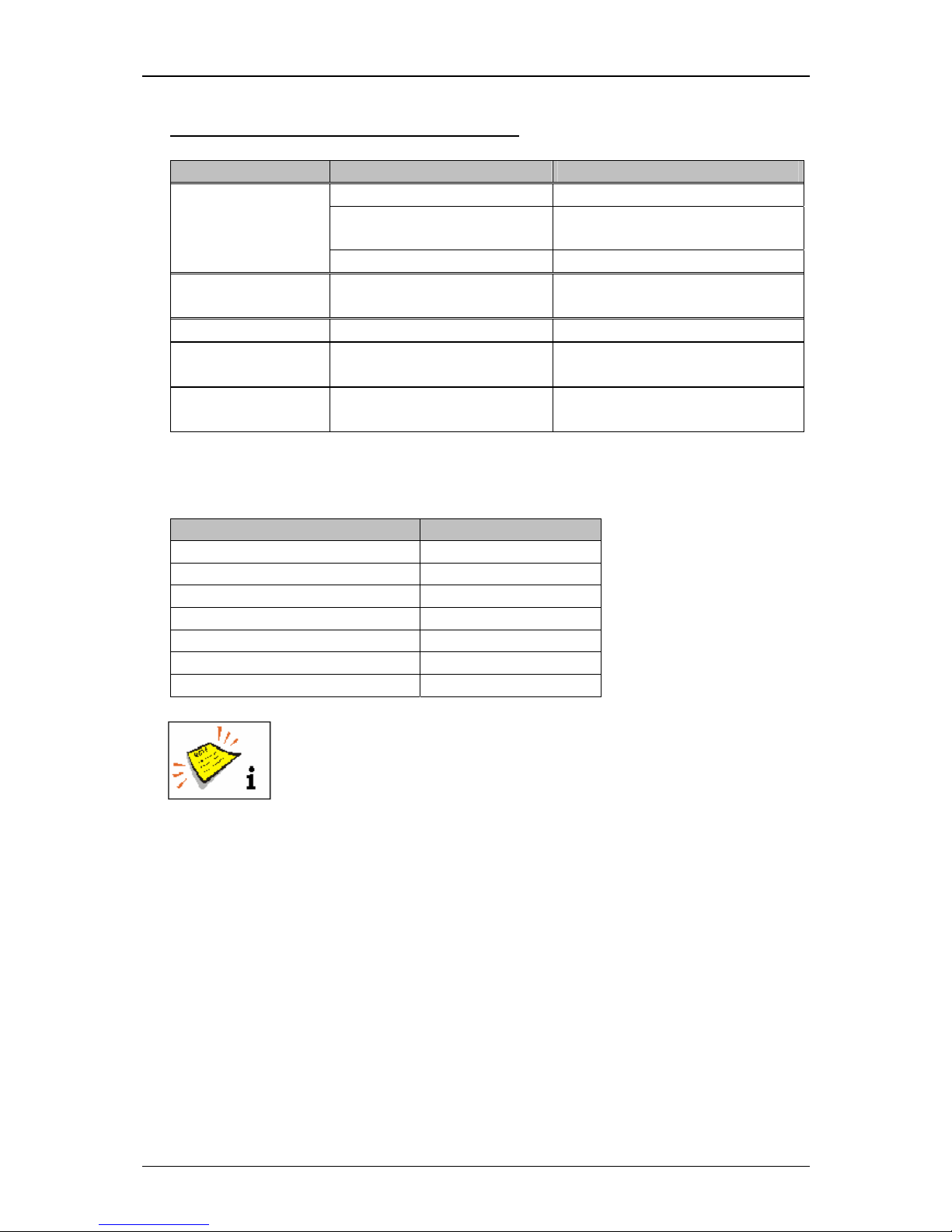
Basic data /Recommended working conditions:
Signal Parameter Value
Input level High 15 up to 30V
Input level Low -3,5V up to 3,5V (or high
resistance)
All signals
Input resistance 6,8kOhm
Increment Counter/
Reset Counter
Minimum pulse width 250µs
Power ON Minium pulse width 2,5 s
Jobselect 0-9 Maximum duration
of bounce
10 ms
(2)
Input 0-5 Minimum pulse widths Depending on assigned function
(see following table)
In the following table you will find the minimum pulse widths which are required to
release the assigned function at the X4 plug.
Function Minium pulse width
Open nozzle 300ms
Close nozzle 300ms
Print start 500ms
Print stop 500ms
Turn off printer 750ms
Mirrored horizontally 200ms
Gauger synchronization signal 200ms
The function allocations of the inputs 0 up to 5 happens by the
software of the JET3 in the menu Settings X I/O-Settings X Inputs.
You will find a circuit diagram of the interface in the appendix of this
manual!
(1)
All 24V inputs which are designated with (1) are protected by a self-reset fuse with 700 mA.
(2)
For a change of the Jobselect inputs it has to be carried out within the duration of bounce,
that means only after termination of this period of time the new Jobselect No. is validated.
Page 39
Group 5 Transport/Start up Page 39
Release R1.03e LEIBINGER JET3
5.4.5 Interface X3 (Outputs)
8 outputs which can be freely selected are available for special functions. The
outputs 1-3 are predefined as a standard and should be not changed.
Output 1 = Print stop error Output 3 = Ready to print
Output 2 = Refill warning
Specifications Output 1-8:
Parameter Value
Driver type 24V high side driver
ON = +24V
OFF = high resistance
Output current max. 700mA/output
max 700 mA totally
(1)
Max. switching frequency 2 kHz
(2)
Max. delay time 100µs
Turn on resistance max. 0,28 Ohm
Features Short-circuit-proof
Overcurrent- and excess temperature –proof
The function allocations of the outputs is carried out with the
software of the JET3 in the menu Settings X I/O-Settings X
Outputs.
You will find a circuit diagram of the interface in the appendix of this
manual!
(1)
All 24V inputs which are designated with (1) are protected by a self-reset fuse with 700mA,
that means the sum of all output currents which are supplied of this 24V should not exceed
700mA.
(2)
Depending on the set function.
Pin Designation Pin Designation
1 Output 1 9 Output 5
2 Output 2 10 Output 6
3 Output 3 11 Output 7
4 Output 4 12 Output 8
5 +24V
(1)
13 Reserved
6 Reserved 14 Reserved
7 Reserved 15 GND
8 GND
Reserved = Do not connect
Plug assignment:
Pin connection:
Page 40
Group 5 Transport/Start up Page 40
Release R1.03e LEIBINGER JET3
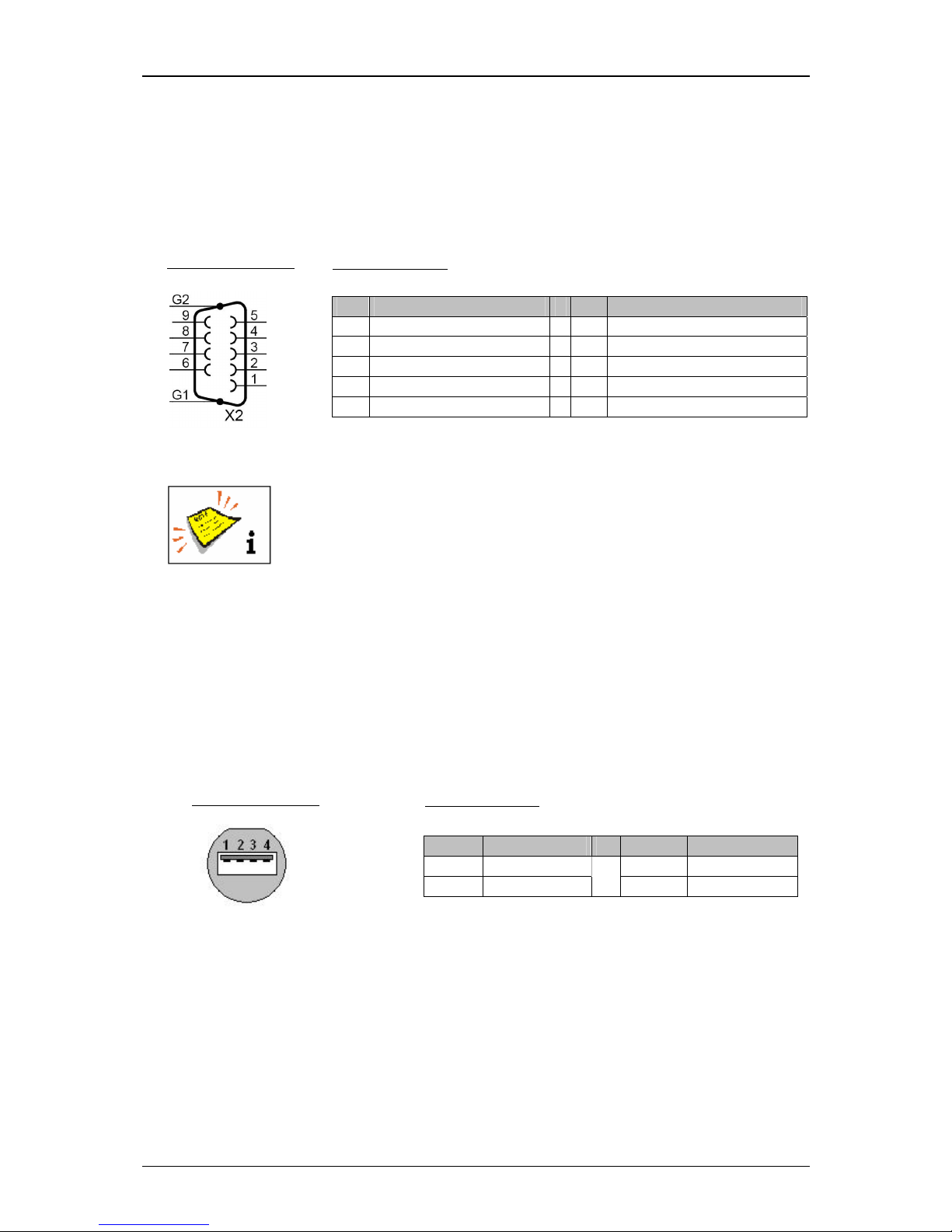
5.4.6 Interface X2 (Serial interface)
The interface “X2” is a serial data interface with a transfer rate up to 115200 Baud.
The access is suitable for a connection to the printer to application-specific software
for the data management and for the remote control of the printer.
The function allocations of the outputs is carried out by the software
of the JET3 in the menu Settings X I/O-Settings X Outputs.
You will find a circuit diagram of the interface in the appendix of this
manual!
5.4.7 USB-Connection
By the USB-connection you can connect all common USB-devices as e.g. mouse,
keyboard or USB-stick very simply. All data can be exchanged comfortable and
simply by the USB-connection. Software updates, exchange of variable printing data
or memory expansions can be carried out simply with the USB-stick.
Pin Designation Pin Designation
1 +V (+5V) 3 Data +
2 Data -
4 GND
Plug assignment:
Pin connection:
Pin Designation Pin Designation
1 NC 6 Connected with 4
2 RxD
7 RTS
3 TxD
8 CTS
4 Connected with 6
9 NC
5 GND
NC = not connected
Plug assignment:
Pin connection:
Page 41
Group 6 Operation – Construction/Structure Page 41
Release R1.03e LEIBINGER JET3
1
4
5
1
3
2
6. Operation
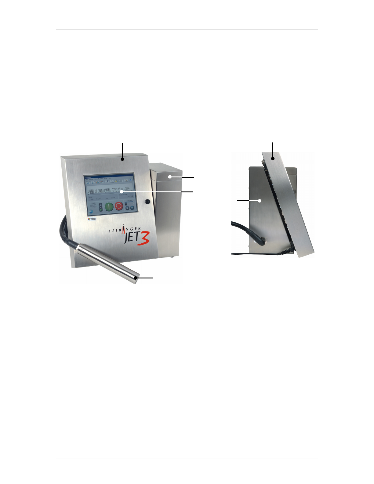
6.1 Construction/Structure of the device
The high-performance LEIBINGER JET3 is manufactured of a solid two parts stainless
steel cabinet. Due to the two parts construction you will get a thermal separation
between the hydraulic- and electronic section. The device consists of the following main
components.
Figure 9
Equipment configuration (General view)
1 – Electronic cabinet 4 – Refilling unit
2 – TFT – Touch Display 5 – Print head with umbilical
3 – Hydraulic cabinet
In the closed electronic cabinet you will find the essential electronic components as
power supply, the TFT-Touch Display as well as the controller board.
The large central arranged TFT-Touch Display describes the interactive interface for the
operator. This central entry medium with its extensive 10,4” color display with backlight
allows a clear, self-explaining operator guidance without additional keys and switches.
In the hydraulic cabinet you find all components which are required for the
transportation and preparation of ink.
The refilling unit provides a supply of consumables. It contains two separate reservoir
tanks for ink and solvent. The unpressurized tanks can be refilled without interrupt
procedure, odorless and splash-free during the operation.
Page 42
Group 6 Operation – Functional principle Page 42
Release R1.03e LEIBINGER JET3
The print head contains all mechanical, electronical and hydraulic components which are
required for the creation of print out. It is connected with the hydraulic cabinet by a
flexible umbilical.
6.2 Functional principle
6.2.1 Method of working
The JET3 works in accordance with the continuous ink jet process. In this a
constant ink jet is emitted from a jet nozzle which is broken down into a series of
equal size drops under the influence of mechanical oscillations.
If required these drops are individually charged up electrostatically and deflected
into a constant electrical field depending on the charge. As a result not just one
point but rather a line of points can be applied contact-free with one jet. If the
product used is moved vertically to the drop deflection two-dimensional patterns
(characters) can be created.
The drops that are not required for a programmed inscription are not charged and
flow uninfluenced through the electrical deflection field into a gutter. In the gutter
the drops are sucked up by a suction pump and fed back into the ink tank.
Depending on the application alphanumeric data and graphics can be entered with
the TFT touch display.
Data for font and texts are stored in the device (even in the event
of power failure). If required it can be called up, altered or deleted
quickly and easily.
Further more, all jobs, fonts and graphics can be saved as a backup e.g. on a USB-stick or a SD-card.
6.2.2 Drop creation
During the drop creation the ink is pressed
through a jet nozzle under pressure and
at the same time modulated in such a way by highly frequent sinus oscillations that
are imposed on the drop that it attaches itself to the nodal points of the oscillations
and breaks down into individual drops at a specific distance lA (please see the
following figure “Creation of a character”) from the jet. The oscillations are created with
an oscillatory system that is excited by a Piezo oscillator.
Page 43

Group 6 Operation – Functional principle Page 43
Release R1.03e LEIBINGER JET3
6.2.3 Drop charging
In order to be able to charge the drops it is necessary for the ink to have electrical
conductivity. This is possible through the use of specific salts that dissociate in the
solvent used. The drop brake-off point of the modulated jet is automatically set in
such a manner that this happens inside the charging electrode.
The drops can now be charged up by creation of voltage between jet and charging
electrode, because they are given a negative charge through the charge shift
resulting in the charge electrode gap. A specific charge voltage is clearly allocated
for each drop charge.
6.2.4 Drop deflection
After the drops have left the charging electrode they fly through an electrical field.
Here, those droplets that were previously charged in the charging electrode are
deflected. The drops that have not been charged fly straight ahead into the gutter.
Here they are sucked up and fed back to the circular flow of ink. The charged drops
are only deflected in one direction, the other direction is performed by the product
to be inscribed.
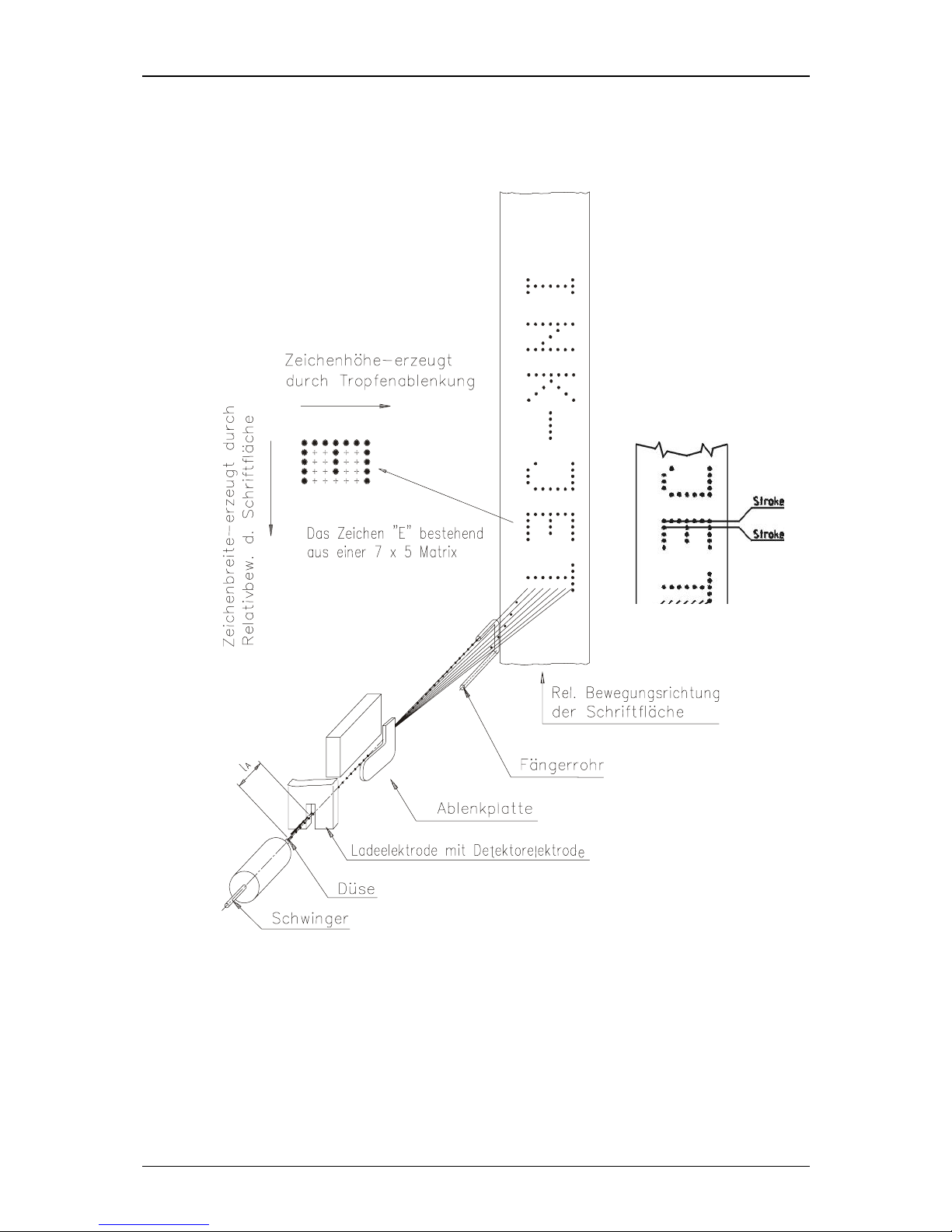
6.2.5 Creation of a character
Each character is defined by a two-dimensional matrix, e.g. 7 x 5. An ink drop can
be assigned to every point of intersection. The character is formed by deflecting the
ink drops in a vertical direction and by moving the product which is to be imprinted
horizontally. The ink drops which are not to be positioned are not given electrostatic
charges in the charging electrode, and pass through the electrical field without
being deflected and on into the gutter tube. The controller (CPU) of the printer
calculates the values which are required for the generation of charging voltages of
the single characters.
Page 44
Group 6 Operation – Functional principle Page 44
Release R1.03e LEIBINGER JET3
6.2.6 Summary of the individual procedures
Figure 10
Creation of a character
Abriss-Punkt
X
X+1
Character height created
by drop deflection
Drop brake-off point
Character „E“ build with a
7 x 5 matrix
Rel. movement direction of
the description area
Gutter
Deflector plate
Charge electrode with deflector
electrode
Nozzle (jet)
Oscillator
Character width created by the rel. movement of the description area
Page 45
Group 6 Operation – Functional principle Page 45
Release R1.03e LEIBINGER JET3
3
5
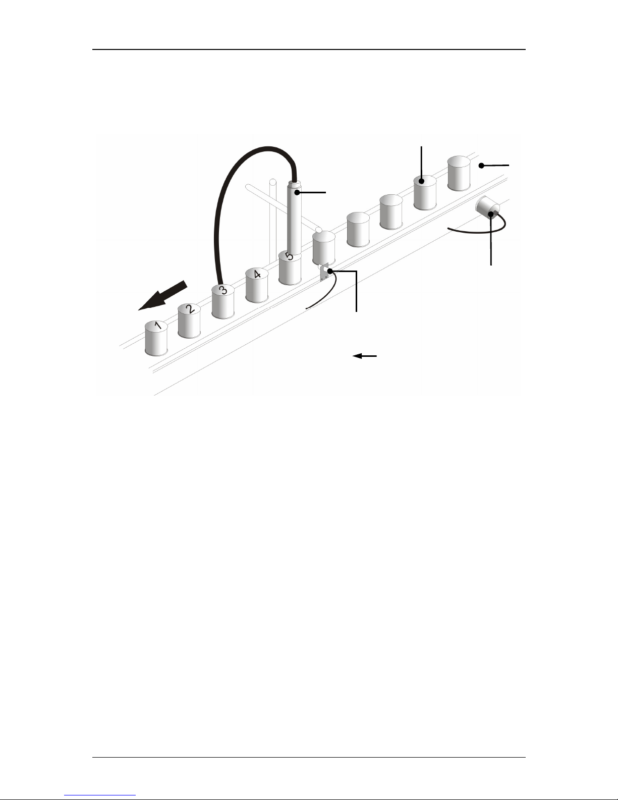
4 2 1
= Direction of conveyance
6.2.7 Example of use
Figure 11
Example of use
1 – Product 3 – Encoder 5 – Print head
2 – Conveyor belt 4 – Sensor
Page 46
Group 6 Operation – Elements and procedures Page 46
Release R1.03e LEIBINGER JET3
6.3 Essential operating- and information elements
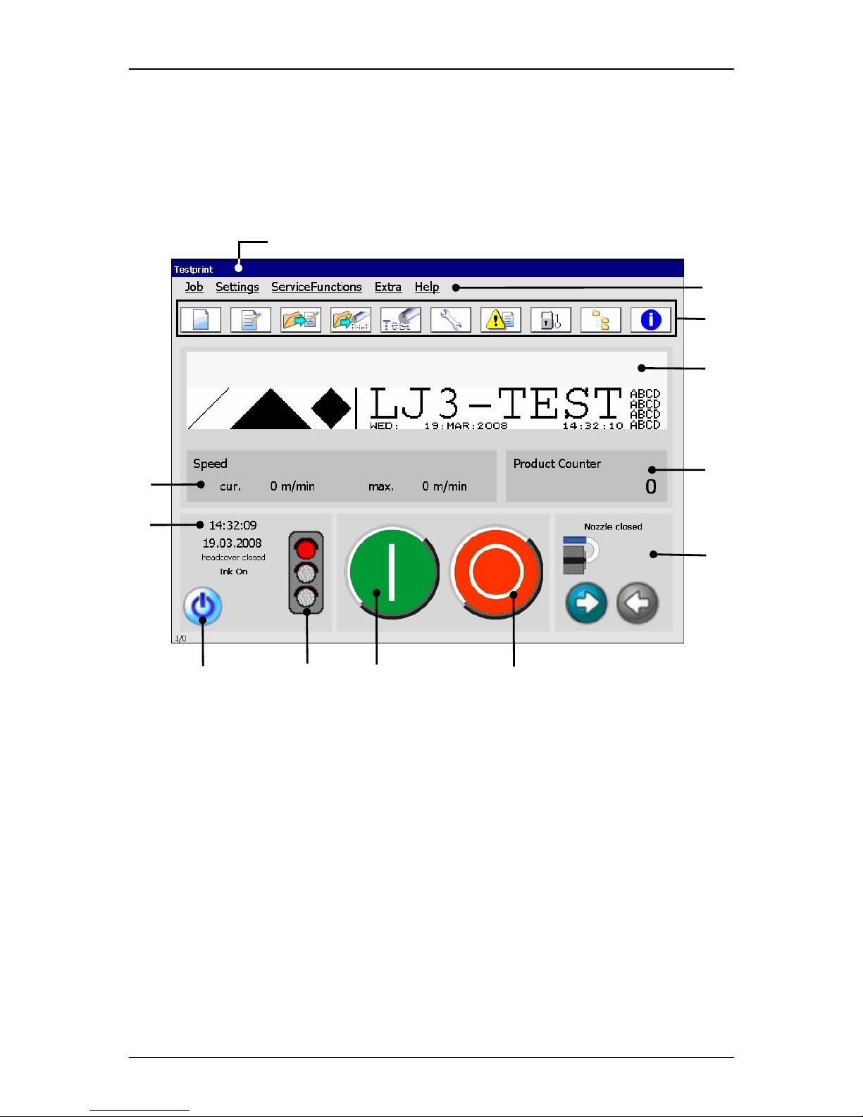
This chapter describes the essential operating- and information elements of the
LEIBINGER JET3 main menu.
Figure 12
Main menu (construction)
1 – Title bar 7 – Status field <General>
2 – Main menu bar 8 – Status field <Nozzle>
3 – Direct buttons 9 – Device status (traffic light)
4 – Display range 10 – Button <Off/Shut down>
5 – Status field <Printing speed> 11 – Button <Printstart>
6 – Status field <Product counter> 12 – Button <Printstop>
Title bar (1): The title bar is displayed at the top of the main menu and contains the
name of the active printing job.
Main menu bar (2): The corresponding menus of the JET3 can be called with the
buttons in the main menu bar. The following menus are available:
Job Servicefunctions Help
Settings Extra
9
1
3
4
2
7 6 8 5
11
12
10
Page 47
Group 6 Operation – Elements and procedures Page 47
Release R1.03e LEIBINGER JET3
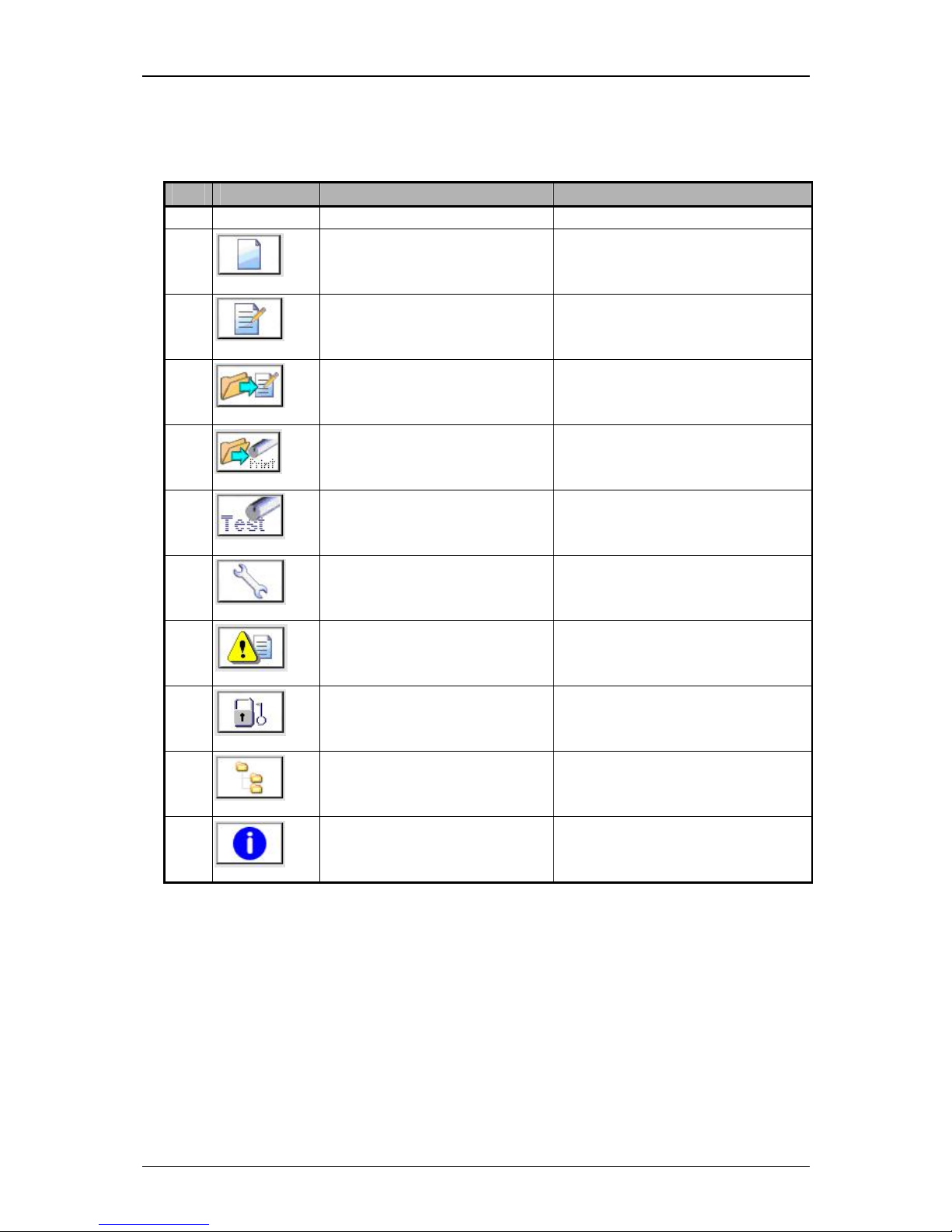
Direct buttons (3): Several menus or submenus of the JET3 can be called directly
with the direct buttons. The following direct buttons are available:
Pos. Button Function-/menu designation Comment
1.
Create new job Editor opens
2.
Edit current job Editor with the current loaded
job opens.
3.
Open job to edit Job selection menu opens.
4.
Open job to print Job selection menu opens.
5.
Test-print function Special appliance for a fast print
control and troubleshooting
6.
Hydraulic/Printhead test and
maintenance menu
7.
Data Logging
8.
Login
9.
Explorer Data file manager to import
jobs, graphics and fonts
10.
Info System information menu opens
Page 48
Group 6 Operation – Elements and procedures Page 48
Release R1.03e LEIBINGER JET3
Display area (4): In this area the printing data of the loaded job which should be
currently printed or loaded is displayed in the WYSIWYG-mode.
Status field <Printing speed> (5): In this field the current reached printing speed as
well as the max. possible printing speed under consideration of the made settings are
displayed. The display is carried out in the measurement m/min or inch/min, depending on the selected adjustments in the basic settings.
Status field <Product counter> (6): The current value of the production counter is
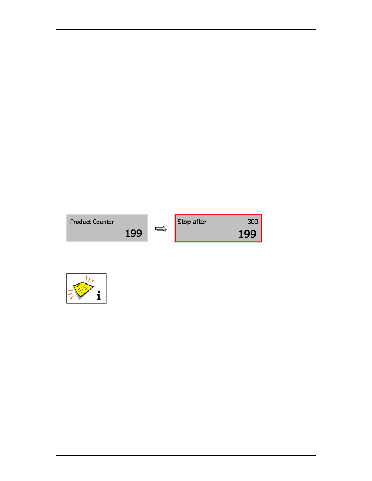
displayed in the field. By pressing on the field you can change or reset the value of
the counter.
If a print stop is defined after a pre-defined amount of prints, the value is also shown
in the status field. For better visualization that a pre-defined print stop has been
defined, the field is displayed with a red frame.
Figure 13
Status field <Product counter>
You will find further information also in the Chapters Reset
Production counter and Change Production counter as well as in the
Chapter Production counter!
Status field <General> (7): In this field the current time, date as well as the status
of the head cover and the ink supply are displayed.
Page 49
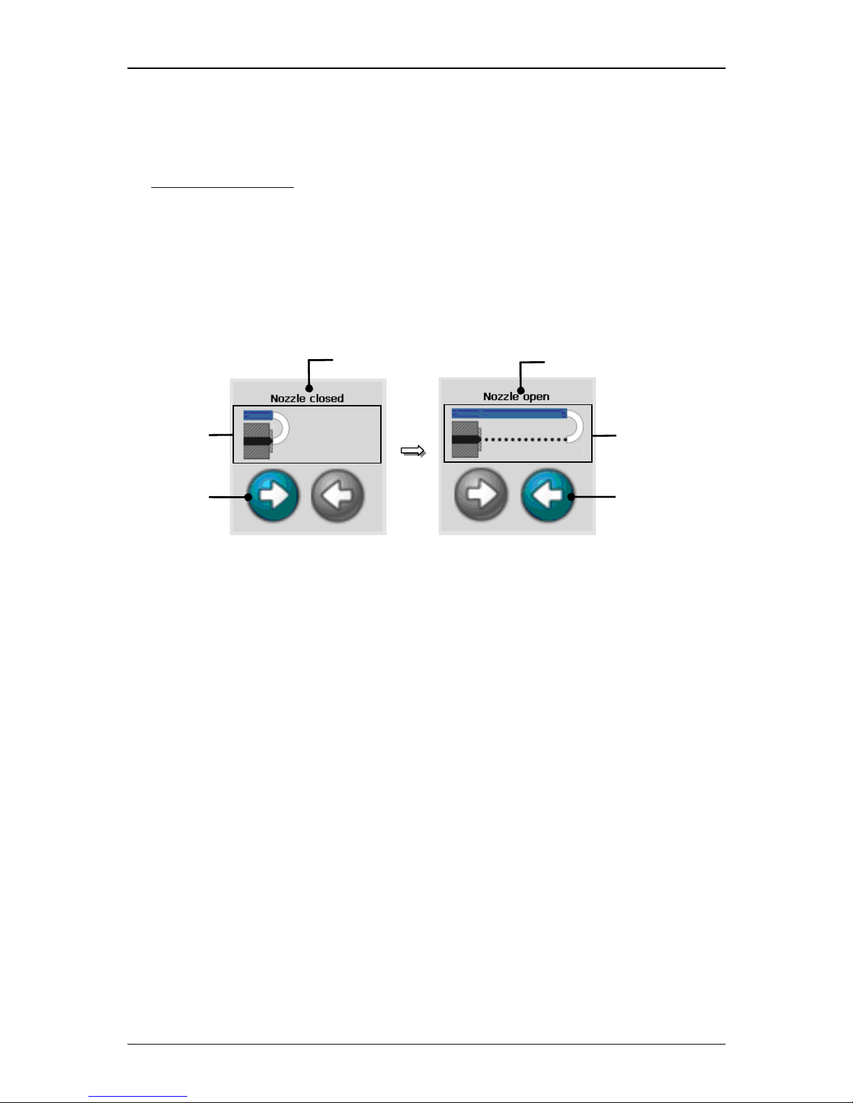
Group 6 Operation – Elements and procedures Page 49
Release R1.03e LEIBINGER JET3
Status field <Nozzle> (8): This field shows the current operating condition of the
nozzle and enables the opening or closing of the nozzle. The condition is displayed in
the form of a text message (1) and of an active visualization graphic (2).
Operating conditions:
Opening nozzle Nozzle open
Closing nozzle Nozzle closed
With the buttons <Opening nozzle> (3) and <Closing nozzle> (4) you can open or
close the nozzle. The executable button is backgrounded blue-grey.
Figure 14
Status field <Nozzle>
1 – Status report 3 – Button <Opening nozzle>
2 – Visualization field 4 – Button <Closing nozzle>
3
4
1
2
1
2
Page 50
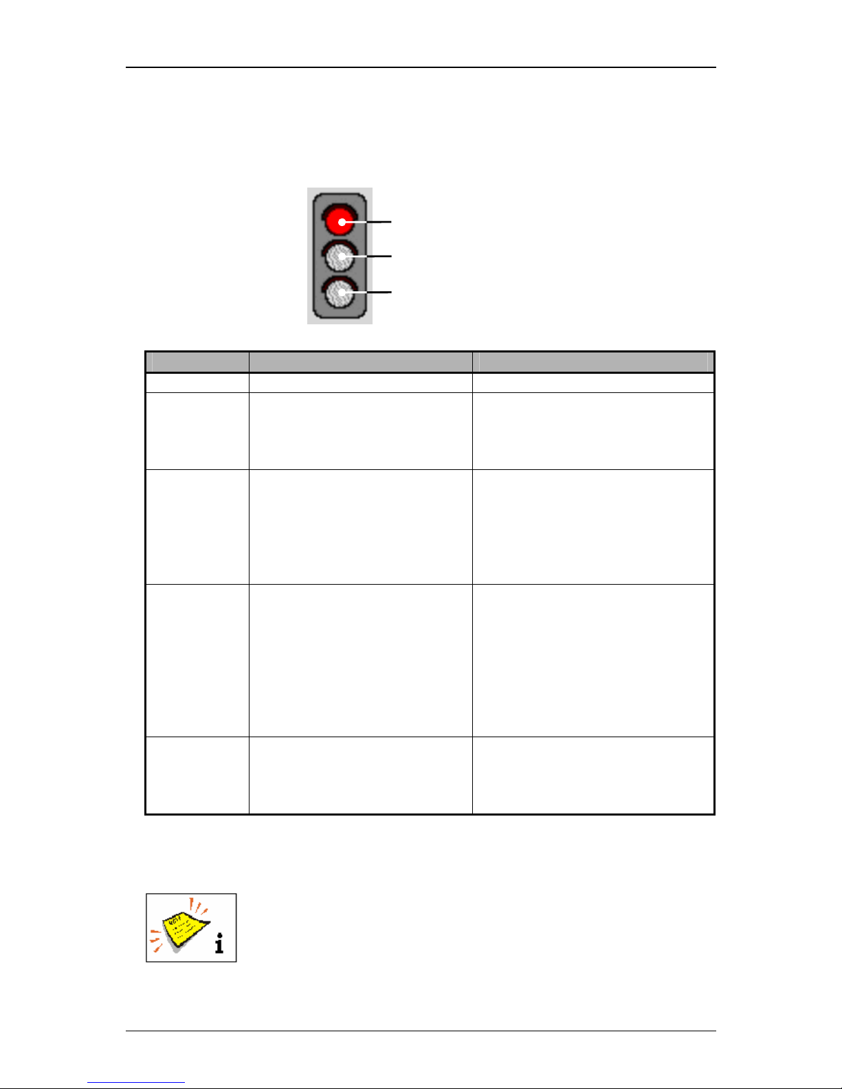
Group 6 Operation – Elements and procedures Page 50
Release R1.03e LEIBINGER JET3
Device status (traffic light) (9): The status traffic light visualizes the current
condition of the JET3.
Figure 15
1 – red LED
2 –yellow LED
3 – green LED
Status traffic light
Display Device status Causation/Comment
all LEDs off No errors or warnings are
pending, but the LJ3 is not
ready to change to the print
mode.
e.g.: Nozzle is closed, head cover
is open, etc.
red LED on An error is pending which
requires an immediate
intervention of the operator to
get the print readiness or to
continue an active print
process.
e.g.: Phasing error, PrintGo-error,
HV-error, etc.
yellow LED
on
An intervention of the operator
is required in the foreseeable
future because an warning is
pending.
If the JET3 is in the print
mode, the print process will be
continued.
z.B.: Refill, Leakage, etc.
If the message is acknowledged
without changing the condition
(e.g. no refill has been carried out)
the message will appear again
after one minute.
green LED on The printer signalizes the
readiness to print or that it can
be switched to the active print
mode.
The button <Print stop> is
illuminated.
Button <Off> (10): With this button you can switch off the device.
You will find further information also in the Chapter Switch
off
device!
1
2 3
Page 51
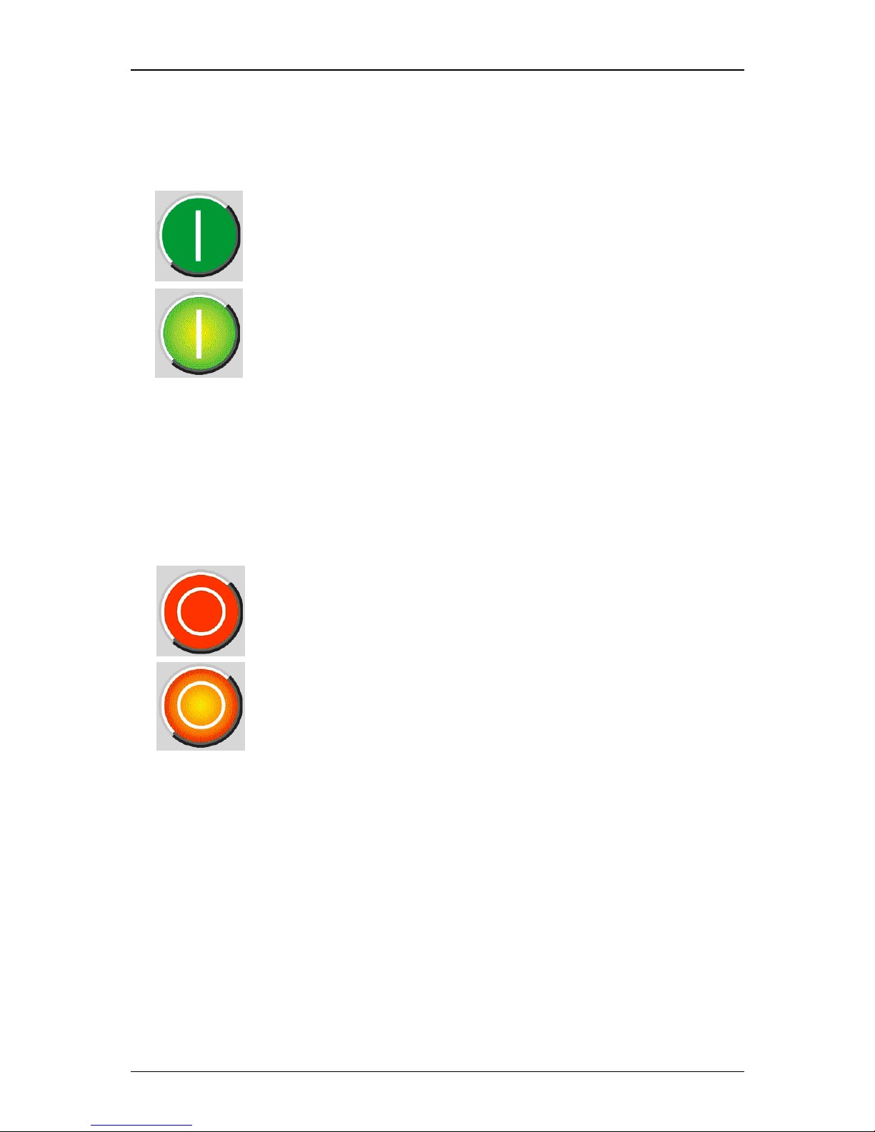
Group 6 Operation – Elements and procedures Page 51
Release R1.03e LEIBINGER JET3
Button <Printstart> (11): With this button the print job will be released for
processing. If a print job is activated, the button is displayed backlighted. It will be
printed as soon as a PrintGo is released.
= Print start inactive (Print job is not released for processing)
= Print start active (Printer is in active print mode)
To carry out a print process, you have to enter a text or you have to select an
existing job. You will find further information regarding this topic in the group
Jobeditor.
Button <Printstop> (12): The released print job is stopped with this button. If a
print stop is activated, the button is displayed backlighted.
= Print stop inactive
= Print stop active (current print job is stopped or no job for
processing is released)
Page 52
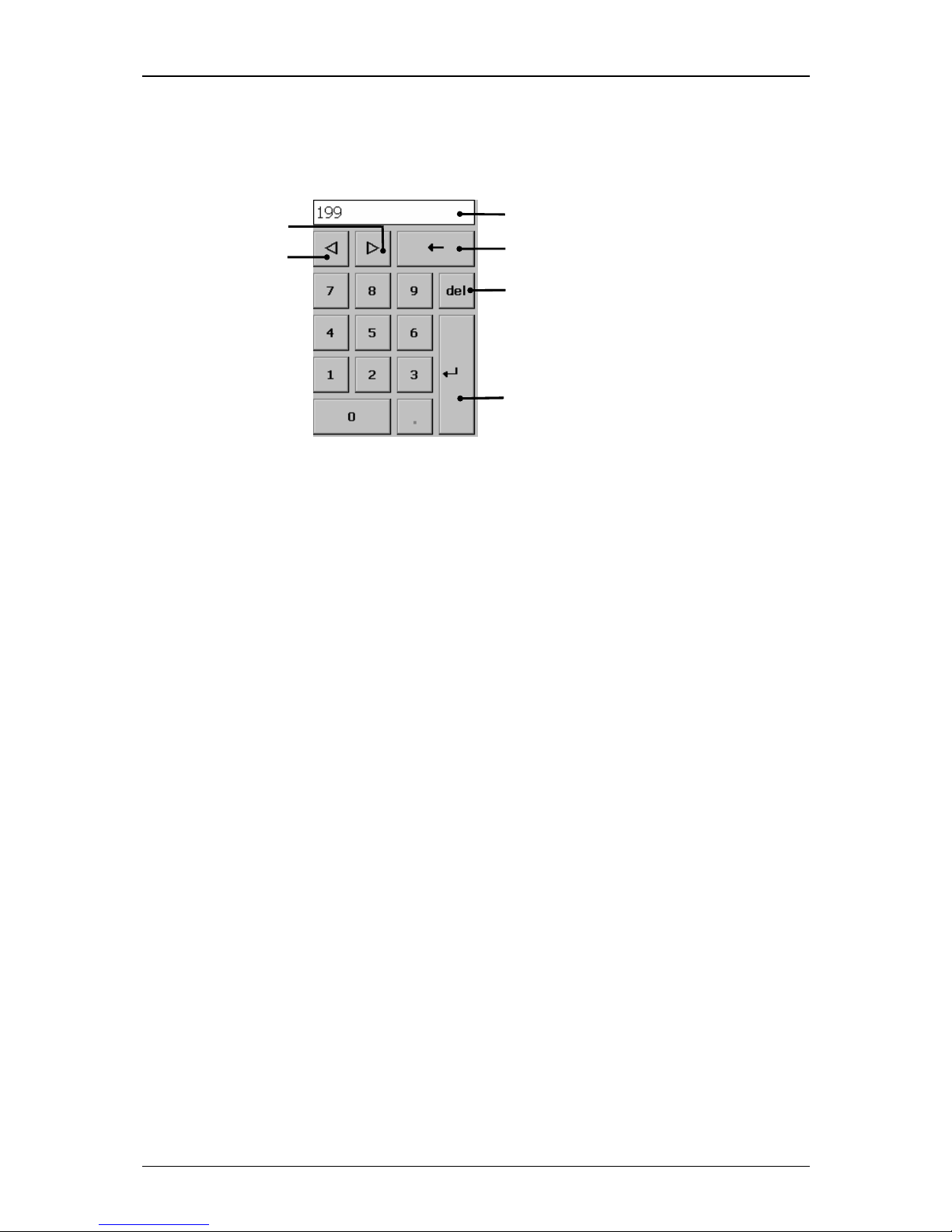
Group 6 Operation – Elements and procedures Page 52
Release R1.03e LEIBINGER JET3
6.3.1 Number blocks
Figure 16
1 – Display
2 – Button <Backspace>
3 – Button <del>
4 – Button <Z>
5 – Button <Y>
6 – Button <Return>
Structure of the number blocks
The figures are entered with the number blocks.
The entered value is shown in the Display (1).
The button < Backspace ←> (2) deletes the character in front of (to the left of) the
current cursor position.
The button <del> (3) enables the deletion of the characters behind (to the right of)
the current cursor position.
With the button <Z> (4) you can shift the current
cursor position by one digit to
the right.
With the button <Y> (5) you can shift the current cursor position by one digit to
the left.
With the button <Return ↵> (6) you can take over the input and the number block
closes.
2
3
6
1
4
5
3
6
Page 53
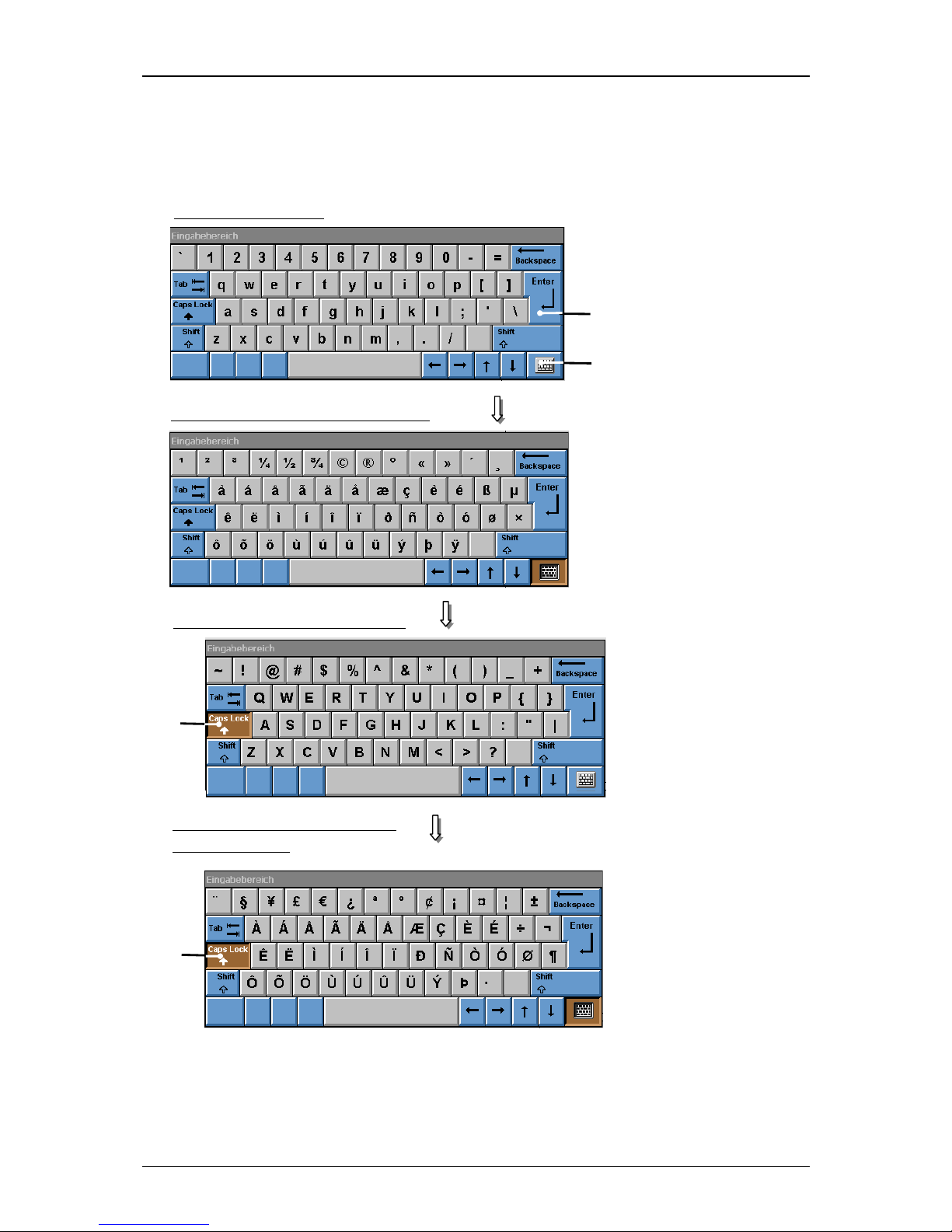
Group 6 Operation – Elements and procedures Page 53
Release R1.03e LEIBINGER JET3
6.3.2 Keyboard fields
Figure 17
Structure of keyboard field
1 –Button <Return> 3 – Button<Caps Lock>
2 –Button <Special characters>
2
1
Standard characters
Special characters (advanced font)
1
Caps Lock/Standard characters
Caps Lock/ Special characters
(advanced font)
1
Page 54

Group 6 Operation – Elements and procedures Page 54
Release R1.03e LEIBINGER JET3
The characters are entered with the keyboard fields. The structure of the keyboard
fields corresponds to the common computer keyboards.
Note:
Depending on the installed language package (e.g. Cyrillic) the structure can
vary from the shown display.
With the button <Return ↵> (1) the input is taken over and the number block will
be closed.
With the button <Special characters>
(2) you can change between the standard
characters and the special characters.
6.4 Basic operating processes
This paragraph describes the basic operating processes of the LEIBINGER JET3.
6.4.1 General
The complete control of the JET3 can be carried out with a connected PC-mouse or
directly with the TFT-Touch-Display.
For the operation with the Touch-Display the control of the device happens by a
slight touch on the buttons (touch-fields) with the finger or with the touch pin
(included in the delivery). Here the targeted precision is decisive and not the
pressure.
The operation with the Touch-Display is described subsequently.
Accidentally touching can release unintentional device conditions.
Page 55
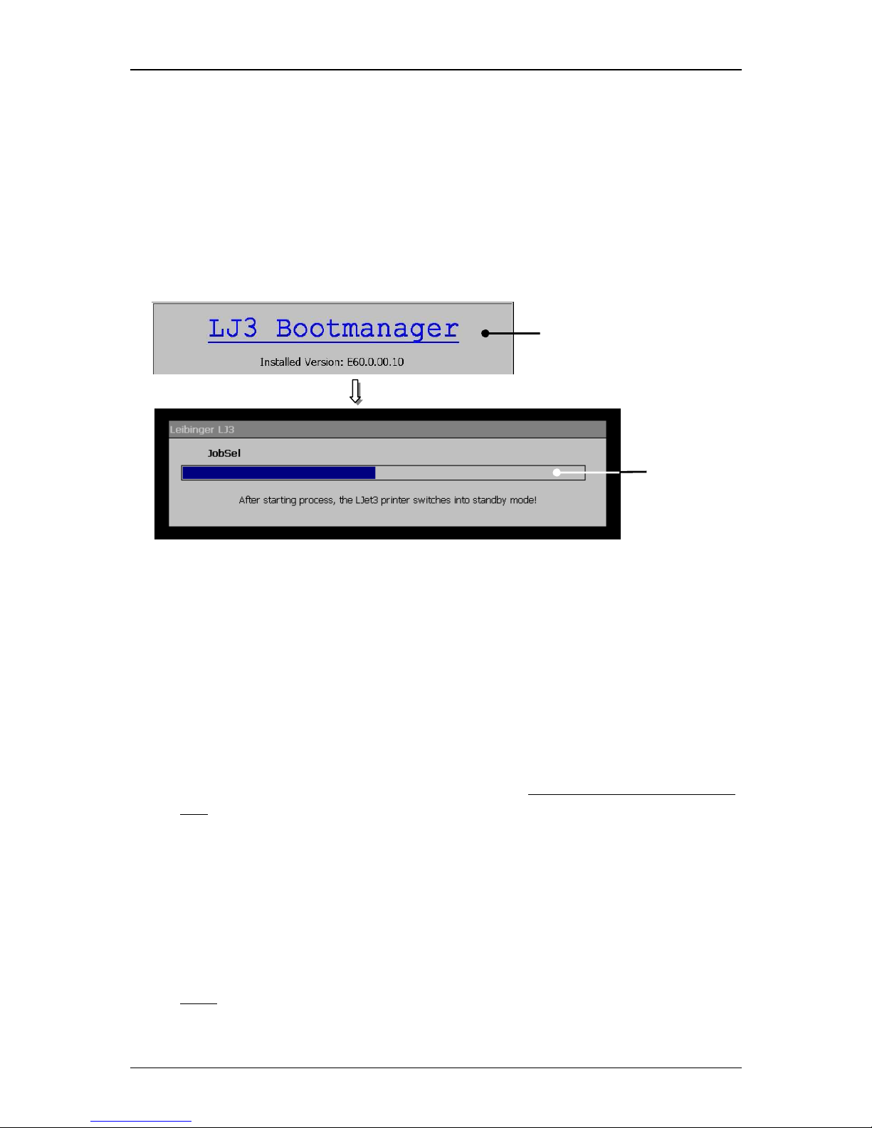
Group 6 Operation – Elements and procedures Page 55
Release R1.03e LEIBINGER JET3
6.4.2 First initialization of the device
After connection to the mains power or after a power interruption, the initialization
of the device will be carried out automatically. For this procedure the boot-manager
is started. The progress of the initialization is shown by a bar. After finishing the
process the device is switched to the standby-mode (monitor is dark) and the JET3
is now ready to switch on by pressing the touch screen.
Figure 18
Initialization process
1 – Bootmanager 2 – Progress display
6.4.3 Switch on device
6.4.3.1 Switching on without password protection
Proceeding:
Touch the dark Touch-Display (1) at any point. Period of touching approx. 2
sec..
The device turns on and the main menu (2) is displayed with the message
<Initialization> (3).
After the initialization the device starts with the bleeding of the system
automatically.
During the process the message <Bleeding> (4) is displayed. The bleeding
takes between 1 – 5 min. The process can be canceled by pressing the button
<Cancel> (5).
Note:
For starting the device the job which has been used at last will be loaded
automatically.
3
2
Page 56
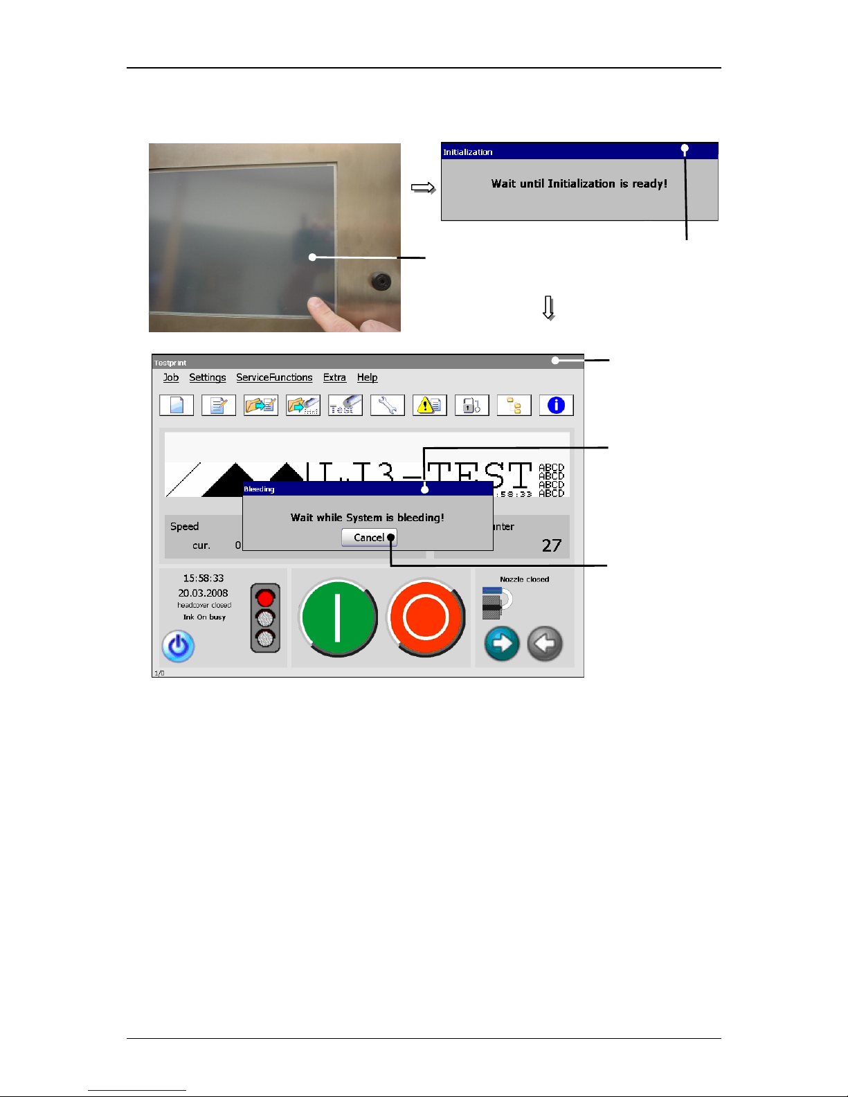
Group 6 Operation – Elements and procedures Page 56
Release R1.03e LEIBINGER JET3
Figure 19
Switch-on procedure without password protection
1 – TFT-Touch-Display 4 – Message <Bleeding>
2 – Message <Initialization > 5 – Button <Cancel>
3 – Main menu
1
5
3
2
4
Page 57
Group 6 Operation – Elements and procedures Page 57
Release R1.03e LEIBINGER JET3
6.4.3.2 Switching on with password protetction
Proceeding:
Touch the dark Touch-Display (1) at any point. Period of touching approx. 2
sec..
The device turns on and the main menu (2) is displayed with the message
<Initialization> (3).
After the initialization the device starts with the bleeding of the system
automatically.
During the process the message <Bleeding>
(4) is displayed. The bleeding
takes between 1 – 5 min. The process can be canceled by pressing the button
<Cancel> (5).
Note:
For starting the device the job which has been used at last will be loaded
automatically.
The dialog field <Current login> (6) and a keyboard field (8) is faded in.
You will find further information regarding the operation with
keyboard fields in the Chapter Keyboard fields!
Enter your password with the keyboard field.
Press the button <Enter> (9) of the keyboard field to finish the input.
Now press the button <Login> (10) to finish the login.
Attention! The login can be also carried out without a password.
In this case only several basic functions of the device are
available for the user.
You will find further information in the Chapter Password
protection!
Page 58
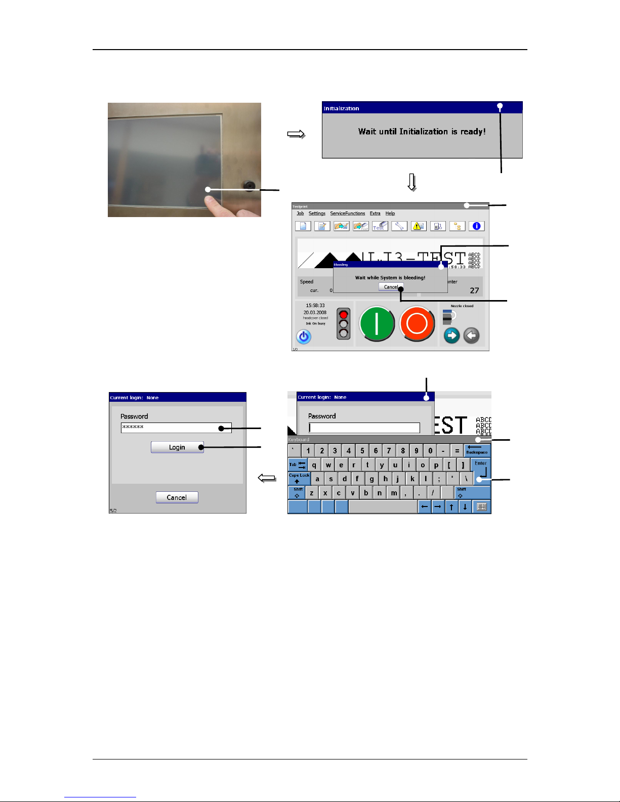
Group 6 Operation – Elements and procedures Page 58
Release R1.03e LEIBINGER JET3
Figure 20
Switch-on procedure with password protection
1 – TFT-Touch-Display 6 – Dialog field <Current login>
2 – Message <Initialization> 7 – Input field <Password>
3 – Main menu 8 – Keyboard field
4 – Message <Bleeding> 9 – Button <Enter>
5 – Button <Cancel> 10 – Button <Login>
1
5
3
2
4
6
8
9
10
7
Page 59
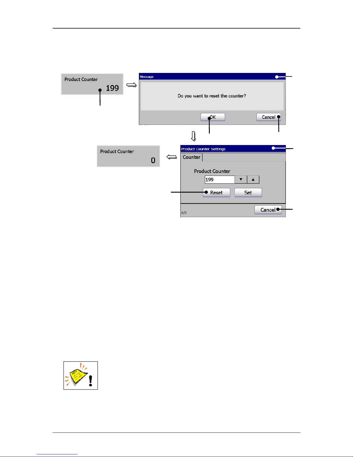
Group 6 Operation – Elements and procedures Page 59
Release R1.03e LEIBINGER JET3
6.4.4 Reset product counter
Figure 21
Reset product counter
1 – Status field <Product Counter> 5 – Window <Product counter settings>
2 – Message <Safety query> 6 – Button <Reset>
3 – Button <OK> 7 – Button <Cancel>
4 – Button <Cancel>
Proceeding:
Press on the status field <Product counter> (1).
A safety query (2), if the counter should be really reset is faded in.
Confirm the reset by pressing on the button <OK>
(3) or cancel the process
with the button <Cancel> (4).
The window <Product Counter Settings> (5) is faded in.
Confirm the reset of the counter again by pressing on the button <Reset>
(6)
or cancel the process with the button<Cancel> (7).
Attention! If job counters (object counters) whose existing settings
<Counter Reset>
have been applied with the attribute „Product
Counter“ are available in the current job, they will be also reset.
You will find further information also in the chapter Change product
counter as well as in the chapter Product counter!
1
3
2 5 4
7
6
Page 60
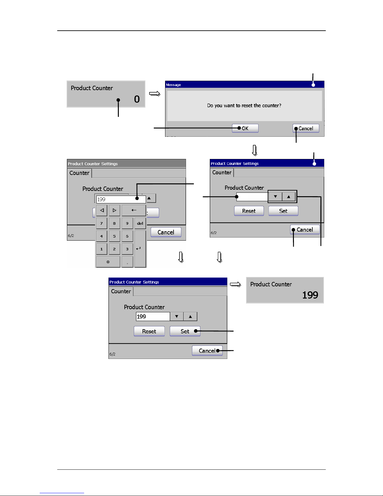
Group 6 Operation – Elements and procedures Page 60
Release R1.03e LEIBINGER JET3
6.4.5 Change product counter (Change value)
Figure 22
Change product counter (change value)
1 – Status field <Product counter> 6 – Arrow buttons
2 – Message <Safety query> 7 – Counter display field
3 – Button <OK> 8 – Number block
4 – Button <Cancel> 9 – Button <Set>
5 – Window <Product counter settings> 10 – Button <Cancel>
5
10
3
2
4
6
9
10
0
oder
8
7
Page 61

Group 6 Operation – Elements and procedures Page 61
Release R1.03e LEIBINGER JET3
Proceeding:
Press on the status field <Product Counter> (1).
A safety query (2), if the counter should be really changed is faded in.
Confirm the query by pressing on the button <OK>
(3) or cancel the process
with the button <Cancel> (4).
The window <Product Counter Settings> (5) is faded in.
Change the value of the counter with the Arrow buttons (6). The value of the
counter will be increased or reduced by pressing on the corresponding buttons.
or
Click in the Counter display field (7). The number block (8) opens for input.
You will find further information regarding the operation with
number blocks in chapter Number blocks!
Confirm the change of values by pressing on the button <Set> (9) or cancel
the process with the button <Cancel> (10).
Page 62
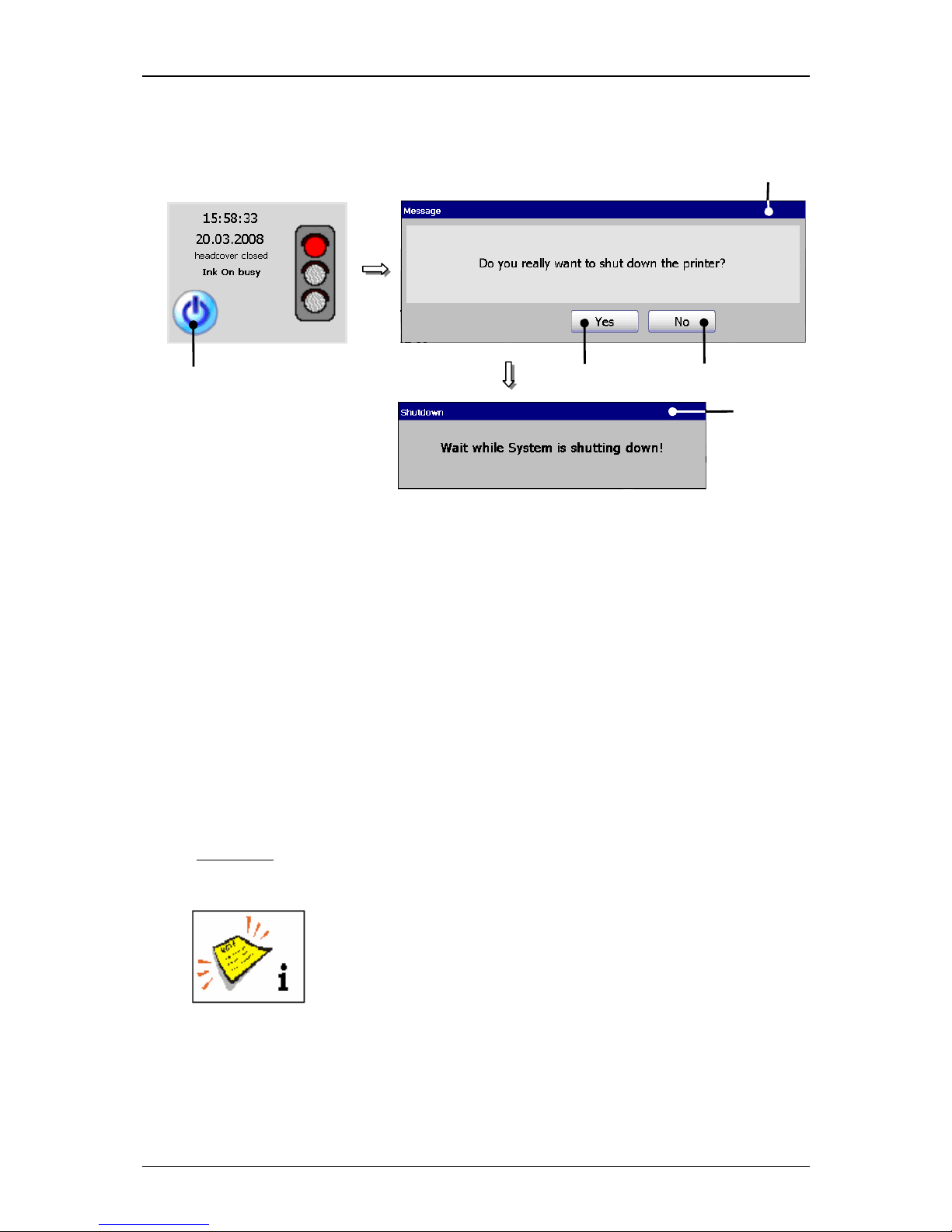
Group 6 Operation – Elements and procedures Page 62
Release R1.03e LEIBINGER JET3
6.4.6 Switch off device
Figure 23
Switch-off procedure
1 – Button <Off> 4 – Button <No>
2 – Message <Safety query> 5 – Message <Shutdown>
3 – Button <Yes>
Proceeding:
Press the button <Off> (1).
A safety query (2), if the printer should be really switched off is faded in.
Confirm the shut down of the device by pressing the button <Yes> (3) or
cancel the process with the button <No> (4) ab.
Now the device is turned off. During the shut down the message <Shutdown>
(5) is displayed.
Comment:
If the nozzle is still open during the turn-off procedure, it will be
closed automatically.
Turning off the device is only possible after a print stop has
been carried out!
After turning off you have to wait approx. 5 sec. to turn on the
device again.
1
3
2
5
4
Page 63
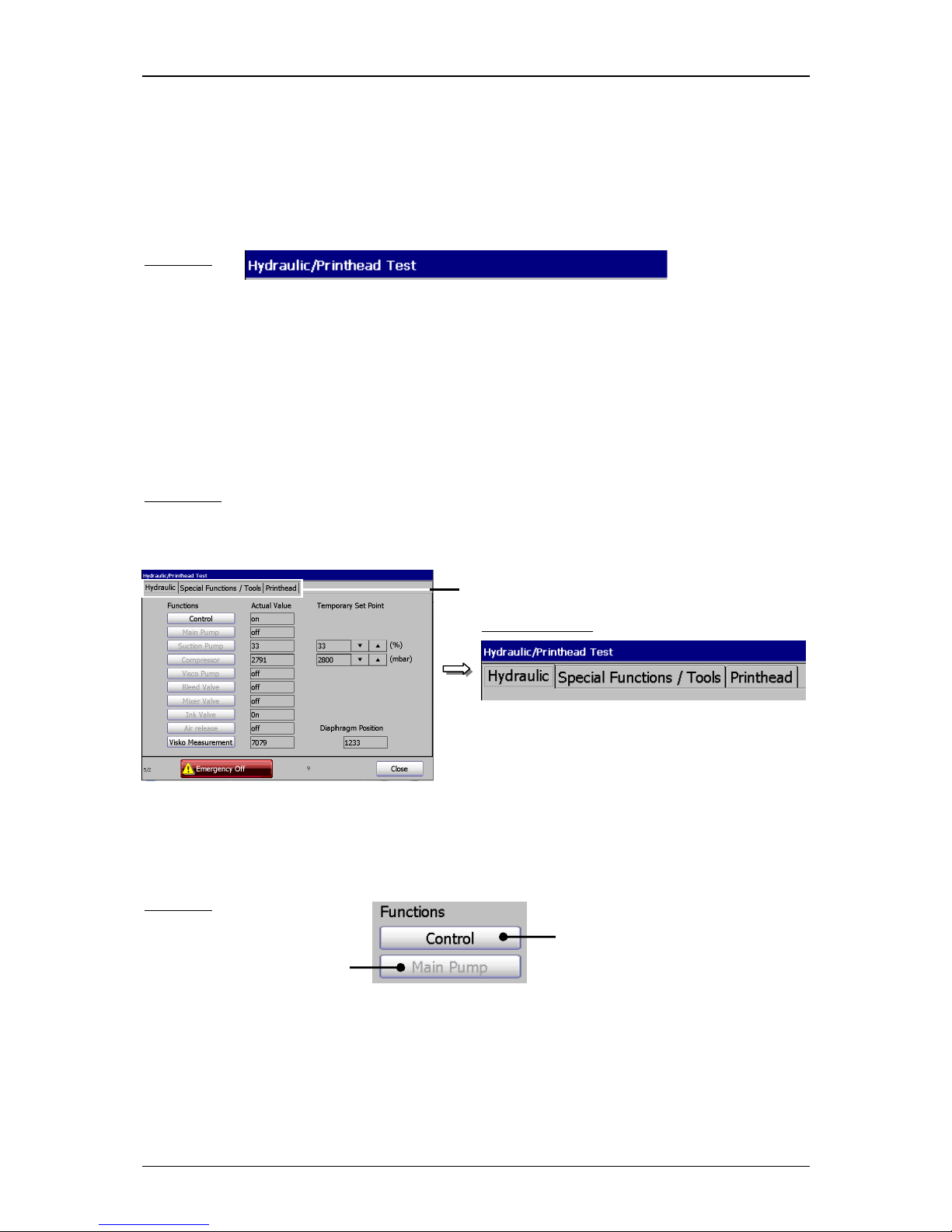
Gruppe 6 Bedienung – Menüaufbau Seite 63
Release R1.03e LEIBINGER JET3
6.5 Menu layout
Title bar:
The title bar is displayed at the top of a menu and contains the designation of the menu.
Example:
Register cards:
Complex menus are divided into so-called registers to get a better clearness. A register
arranges the several menu points to logical functional areas.
The selection of a functional area happens by clicking on the corresponding register
card.
Comment:
The proceeding corresponds to the Window™-standard procedure.
Figure 24
1 – Register cards
Menu layout (Register cards)
Display of functions:
If a function (menu item) is displayed slightly grey, it is not available at the moment.
Example:
1
Register cards:
available
not available
Page 64
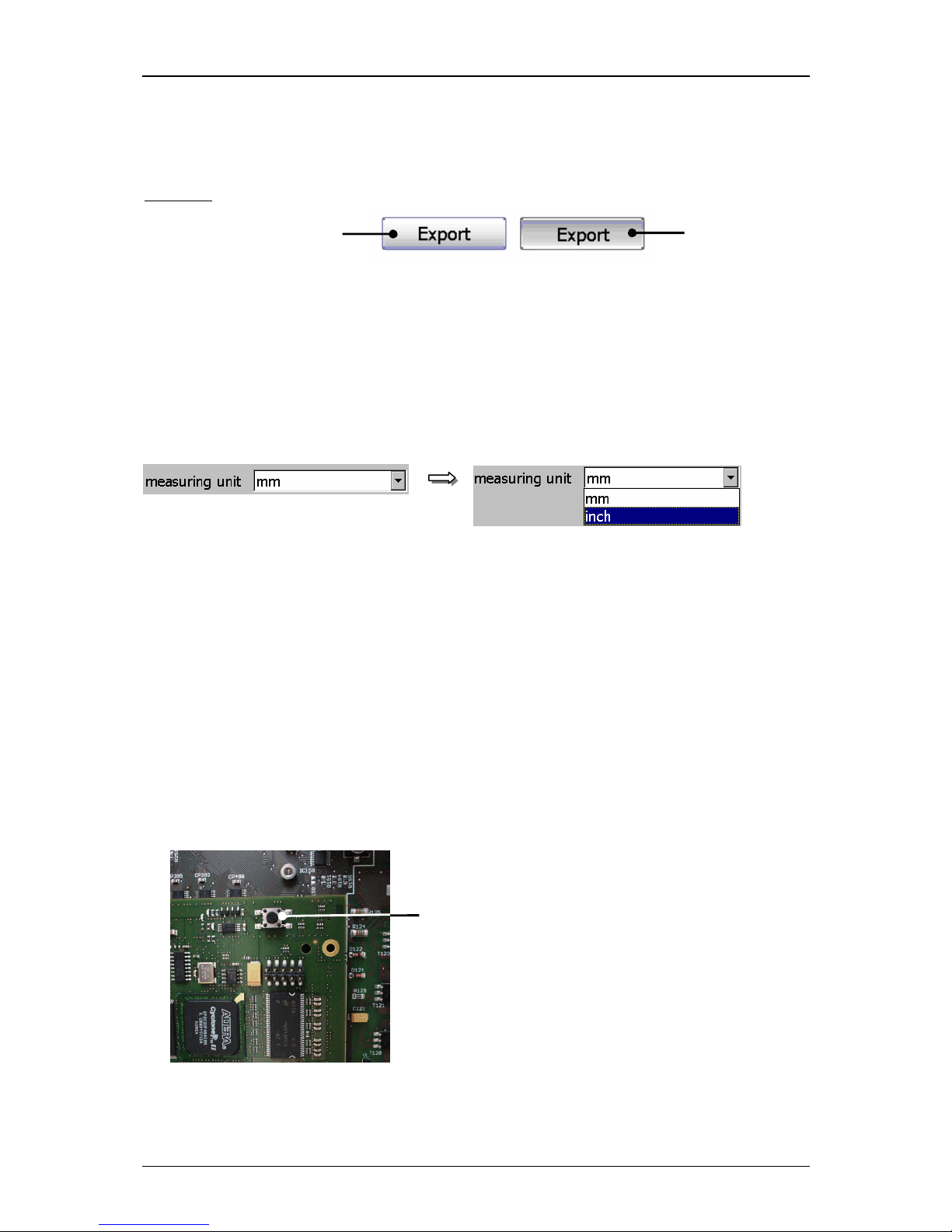
Gruppe 6 Bedienung – Einstellungen und Funktionen Seite 64
Release R1.03e LEIBINGER JET3
If a function is activated or just carried out the background of the button will be
displayed blue-grey during the process.
Example:
Pop-up window:
If several functions can be selected in one menu point or different parameters can be
set, the selection happens by a so-called pop-up window.
Figure 25
Menu layout (Pop-up window)
6.6 Other settings and functions
6.6.1 Carry out Hardware Reset
Reset-switch:
Enables the reset of the electronic in case of error. It is placed in the electronic-
cabinet on the main board (controller board).
Figure 26
1 – Reset-switch
Reset-switch (Hardware Reset)
activated
available, but not
activated
1
Page 65
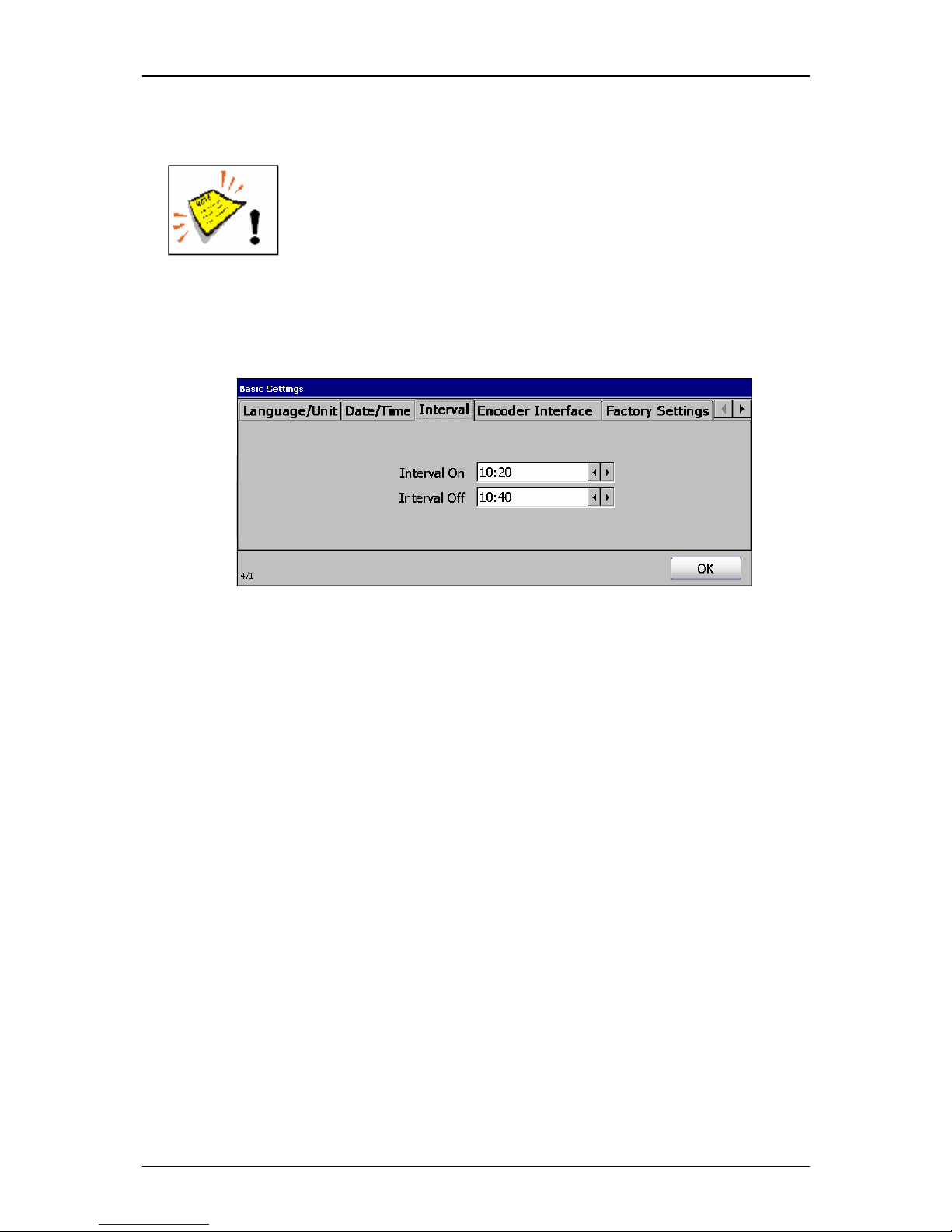
Gruppe 6 Bedienung – Einstellungen und Funktionen Seite 65
Release R1.03e LEIBINGER JET3
6.6.2 Interval operation (integrated clock timer)
The device has to be connected to the mains supply.
The device turns on automatically irrespectively of the ambient
conditions!
The integrated interval function activates the LEIBINGER JET3 automatically in the
on-state according to the times which have been set under the option <Interval>
(“Settings X Basic Settings X Interval“).
The circulation of the ink prevents a drying up of ink and accumulation of ink
components. The viscosity of the ink is constant.
You will find further information regarding setting of interval times in the Chapter
Set Interval Operation!
Page 66

Group 7 Data/Programming Page 66
Release R1.03e LEIBINGER JET3
7. Data entry/Programming
7.1 General
Data which should be printed by the LEIBINGER JET3 can be entered, called, changed
and saved with several input devices, e.g. TFT-Touch display, mouse etc..
The printer can also be programed and controlled with the (RS232/Ethernet) per external
software (according to the Leibinger interface protocol for the LJ3).
Further more the LEIBINGER JET3 can also carry out several functions (e.g. job
selection) by the control with digital signals (e.g. out of a SPS) and can be therefore
also controlled locally.
In the following the operation and programming with the TFT-Touch display are
described.
Page 67
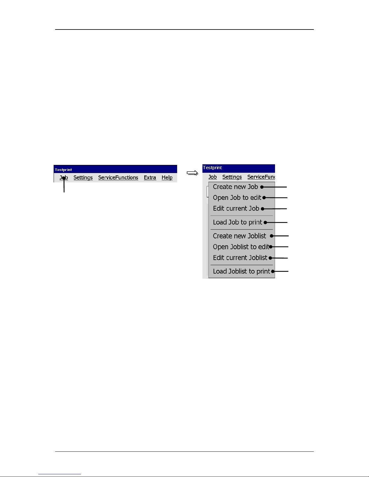
Group 7 Data/Programming Page 67
Release R1.03e LEIBINGER JET3
7.2 Job administration
With the button <Job> in the main menu bar the submenu „Job“ is displayed. The
following options are available:
Create new Job Open Job to edit
Load Job to print Create new Joblist
Edit current Joblist Load Joblist to print
Edit current Job Open Joblist to edit
Figure 27
Menu Job(administration)
1 – Button <Job> 6 – Option <Create new Joblist>
2 – Option <Create new Job> 7 – Option <Open Joblist to edit>
3 – Option <Open Job to edit> 8 – Option <Edit current Joblist>
4 – Option <Edit current Job> 9 – Option <Load Joblist to print>
5 – Option <Load Job to print>
1
2
3
4
5
6
7 8 9
Page 68
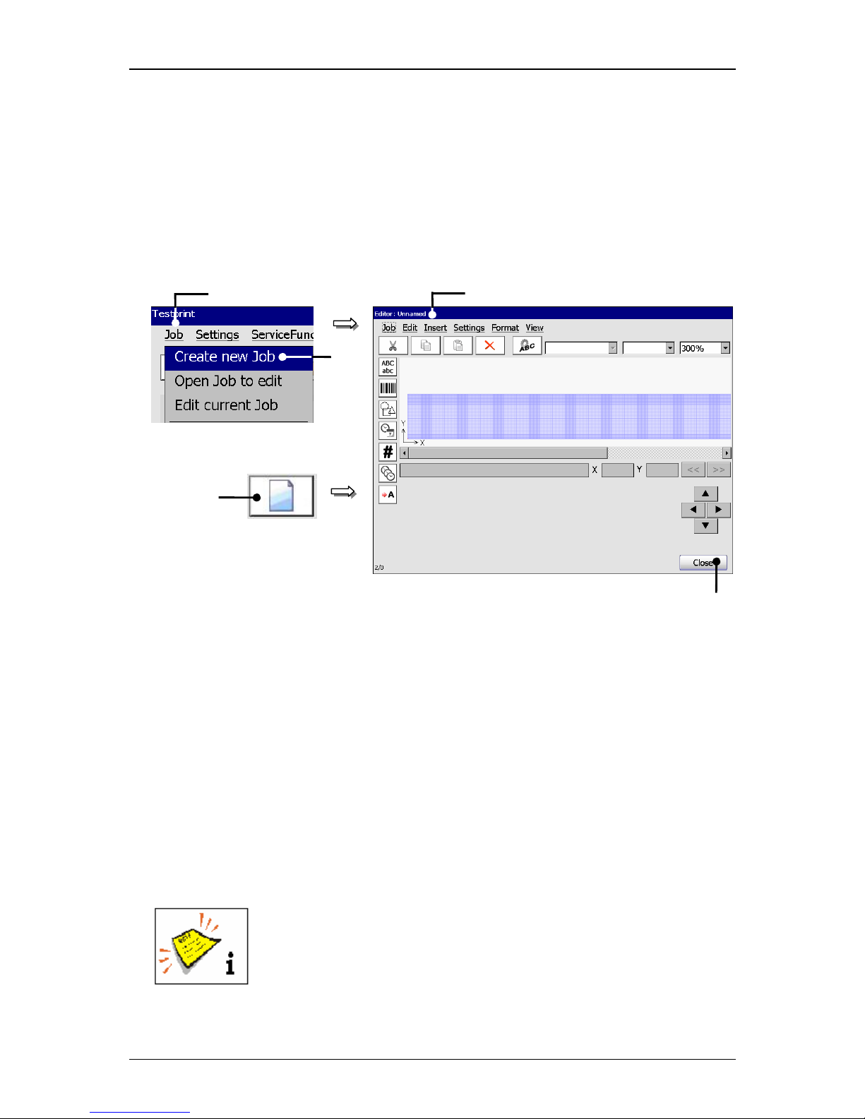
Group 7 Data/Programming Page 68
Release R1.03e LEIBINGER JET3
7.2.1 Create a new job
With the option <Create a new Job> or by pressing on the accordant direct
buutton (Icon) you can create a new job. For creation the job editor opens where
you can create the printing data and save it as a job. A variety of Windows® similar
tools make the operation easier.
Figure 28
Create a new job
1 – Button <Job> 4 – Menu <Jobeditor>
2 – Option <Create new Job> 5 – Button<Close>
3 – Direct button (Icon)
Proceeding:
Press the button <Job> (1) and the option <Create new Job> (2) or press the
accordant direct button [icon] (3).
The menu <Jobeditor> (4) opens to create the printing data.
Carry out the requested inputs and save the job data. You will find further
information regarding the memory process in the group Jobeditor in the chapter
Save job/Save job as.
You will find further information regarding the operation of the job
editor in the group Jobeditor.
1
2
4
or
3
5
Page 69
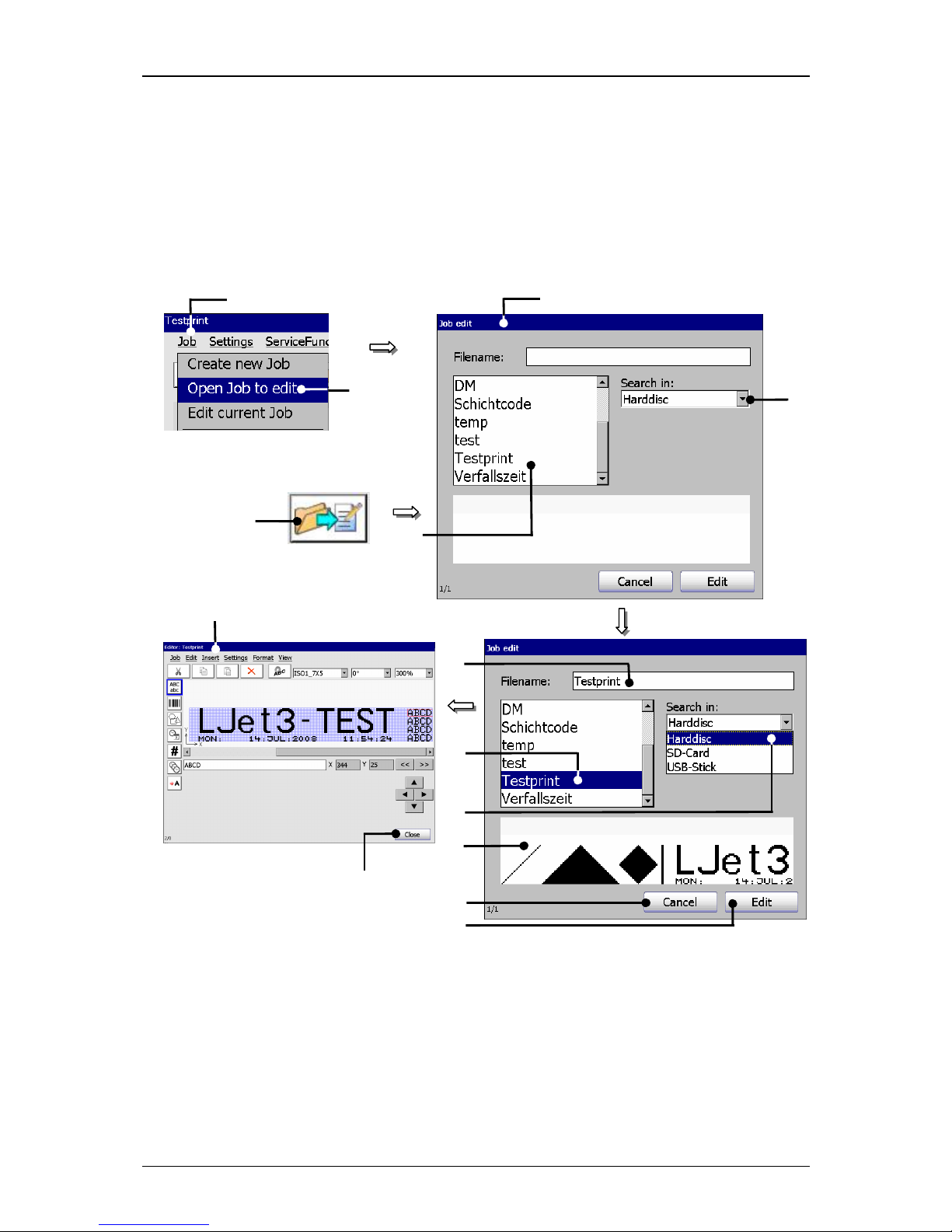
Group 7 Data/Programming Page 69
Release R1.03e LEIBINGER JET3
7.2.2 Open job to edit
With the option <Open Job to edit>
or by pressing on the accordant direct button
(Icon) you can open an existing job for editing. For selection of a job the window
„Job edit“ is faded in.
Figure 29
Open job to edit
1 – Button <Job> 8 – Selected job
2 – Option <Open Job to edit> 9 – Selected data carrier
3 – Direct button (Icon) 10 – Display <Job preview>
4 – Window<Job edit> 11 – Button<Cancel>
5 – Selection field <Job list> 12 – Button <Edit>
6 – Pop-up window <Search in> 13 – Menu <Job editor>
7 – Display <Filename> 14 – Button<Close>
1
2
13
6
4
12
11
7
14
8
10 9 5
or 3
Page 70

Group 7 Data/Programming Page 70
Release R1.03e LEIBINGER JET3
Proceeding
Press the button <Job> (1) and the option <Open Job to edit> (2) or press
the accordant direct button [icon] (3).
The window <Job edit> (4) is faded in.
Select the requested job in the selection field <Job list> (5). With the Pop-up
window <Search in> (6) you can select the various memory locations.
The name of the selected jobs is now shown on the display <Filename> (7).
Additionally a preview of the printing job is faded in on the display <Job
preview> (10).
Press the button <Edit> (12) to take over the selected job or press the button
<Cancel> (11) to cancel the process.
The menu <Jobeditor> (4) opens to change the printing data. The name of the
opened job is displayed in the title bar of the editor.
Carry out the requested changes and save it. You will find further information
regarding the memory process in the group Jobeditor in the chapter Save
job/Save job as.
You will find further information regarding the operation of the job
editor in the group Jobeditor.
Page 71
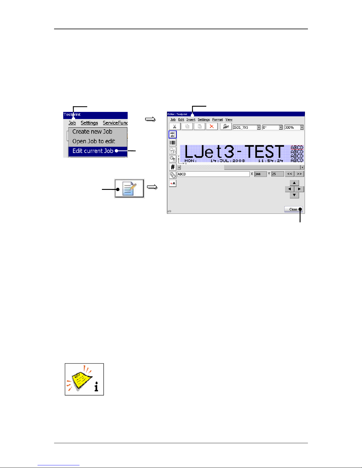
Group 7 Data/Programming Page 71
Release R1.03e LEIBINGER JET3
7.2.3 Edit current job
With the option <Edit current Job> or by pressing on the accordant direct button
(Icon) you can edit the current job.
Figure 30
Edit current job
1 – Button <Job> 4 – Menu <Jobeditor>
2 – Option <Edit current Job> 5 – Button<Close>
3 – Direct button (Icon)
Proceeding:
Press the button <Job> (1) and the option <Edit current Job> (2) or press the
accordant direct button [icon] (3).
The menu <Jobeditor> (4) opens to change the printing data. The name of the
opened job is displayed in the title bar of the editor.
Carry out the requested changes and save it. You will find further information
regarding the memory process in the group Jobeditor in the chapter Save
job/Save job as.
You will find further information regarding the operation of the job
editor in the group Jobeditor.
1
2
4
or 3 5
Page 72
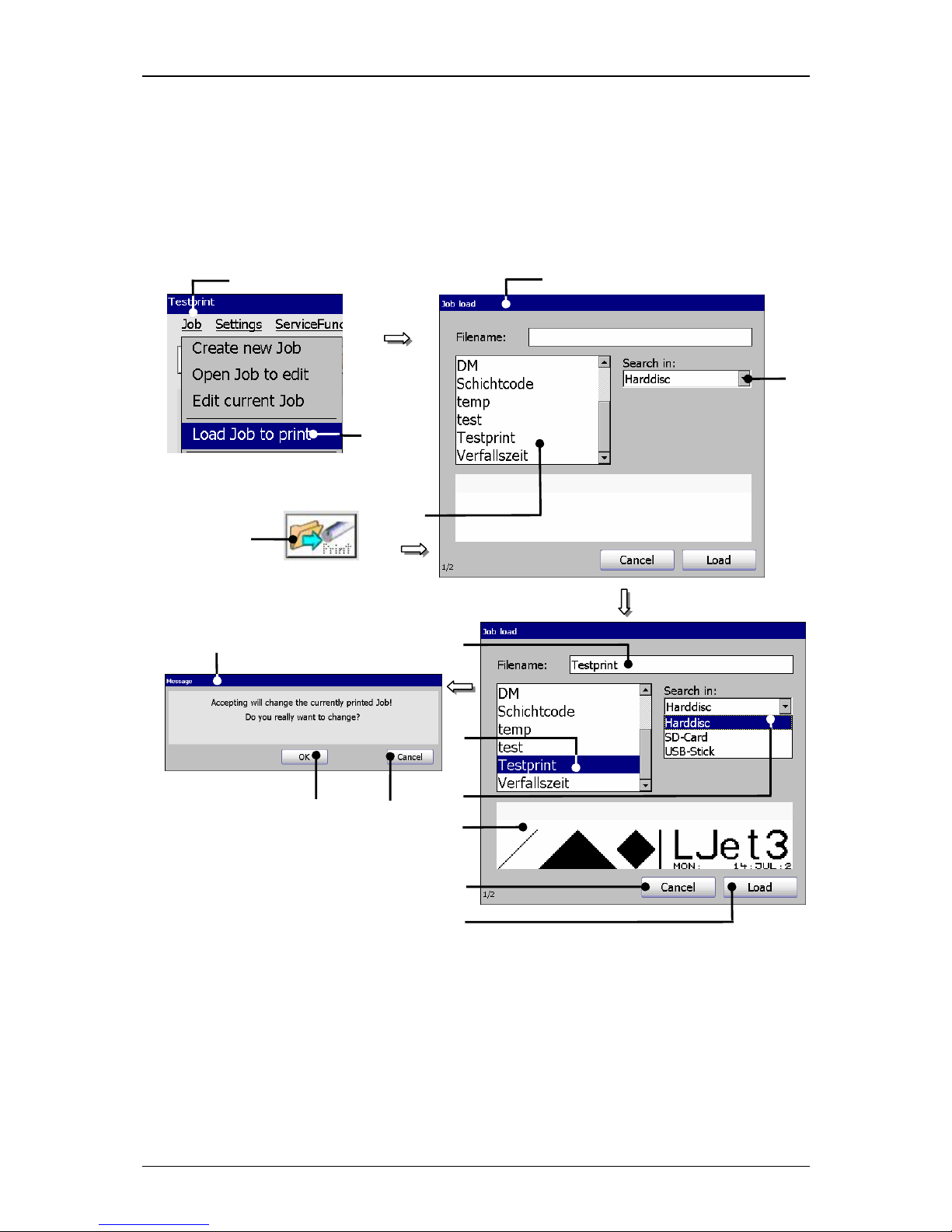
Group 7 Data/Programming Page 72
Release R1.03e LEIBINGER JET3
7.2.4 Load Job to print
With the option <Load Job to print>
you can load (open) a saved job directly for
printing. For selection of a job the window “Load job” opens.
Figure 31
Load job to print
1 – Button <Job> 9 – Selected data carrier
2 – Option <Load Job to print> 10 – Display <Job preview>
3 – Direct button (Icon) 11 – Button <Cancel>
4 – Window <Job load> 12 – Button <Load>
5 – Selection field <Job list> 13 – Message <Change print job>
6 – Pop-up window <Search in> 14 – Button <OK>
7 – Display <Filename> 15 – Button <Cancel>
8 – Selected job
1
2
13
6
4
12
11
7
14
8
1
0 9
15
5
or 3
Page 73
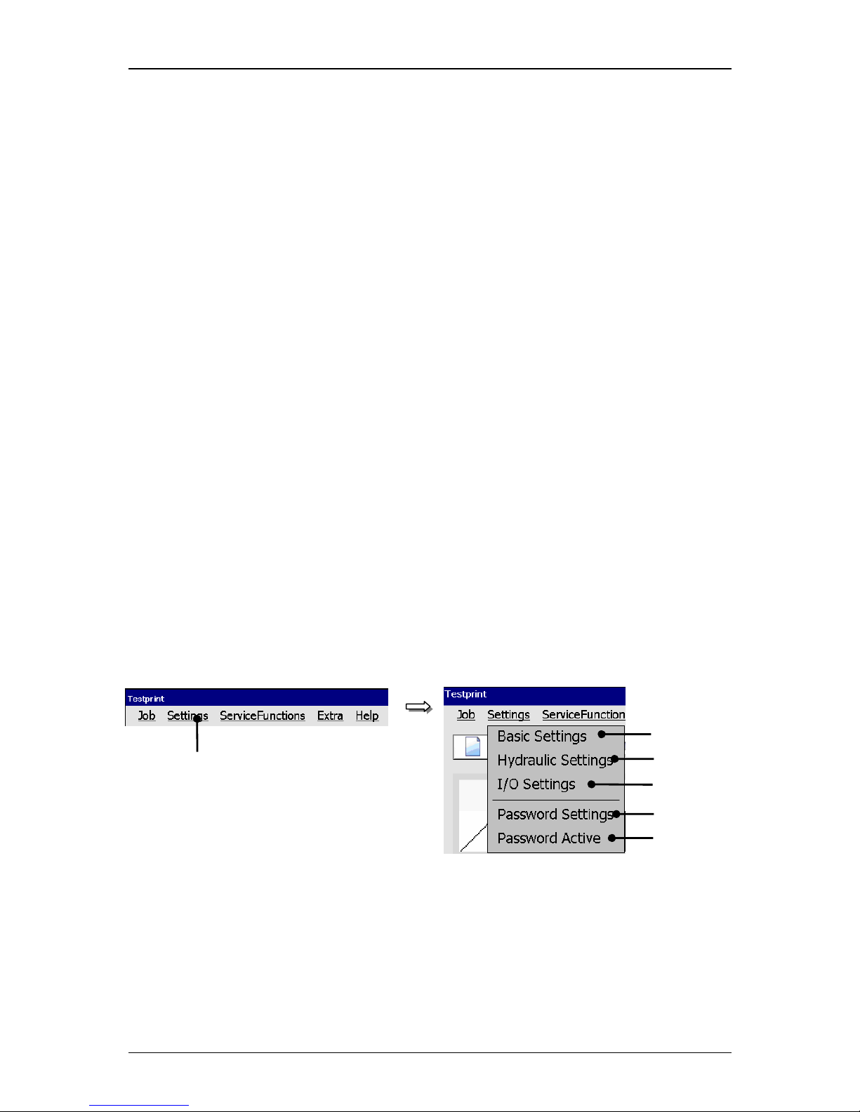
Group 7 Data/Programming Page 73
Release R1.03e LEIBINGER JET3
Proceeding:
Press the button <Job> (1) and the option <Load Job to print> (2) or the
accordant direct button [Icon] (3).
The window <Job load> (4) is faded in.
Select the requested job in the selection field <Job list> (5). With the Pop-up
window <Search in > (6) you can select different memory locations.
The name of the selected job is now shown on the display <Filename>
(7).
Additionally a preview of the printing job is faded in on the display <Job
preview > (10).
Press the button <Load> (12) to take over the selected job or press the button
<Cancel> (11) to cancel the process.
A safety query (13), if the printing job should be really changed is faded in.
Confirm the change by pressing the button <OK>
(14) or cancel the process
with the button <Cancel> (15).
7.3 Settings
With the button <Settings> in the main menu bar the submenu „Settings“ is displayed.
The following options are available:
Basic settings Hydraulic settings I/O settings
Password settings Password active
Figure 32
Menu settings
1 – Button <Settings> 4 – Option <I/O Settings>
2 – Option <Basic Settings> 5 – Option <Password Settings>
3 – Option <Hydraulic Settings> 6 – Option <Password active>
1
2
3
4
5
6
Page 74
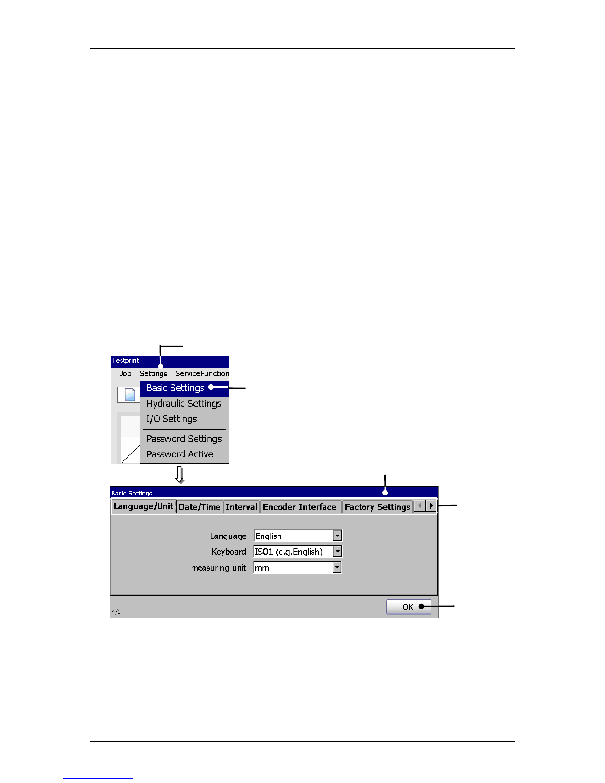
Group 7 Data/Programming Page 74
Release R1.03e LEIBINGER JET3
7.3.1 Basic settings
With the option <Basic Settings> (2) the menu „Basic settings“ (3) opens.
This menu serves as setting of
Language/Unit (Measurement) Interval function Factory Settings
Date/Time Encoder interface IP-address
and to reset the device to the factory settings.
The selection of a functional area happens by clicking on the accordant register card
(4).
Note:
The proceeding corresponds to the Windows™-standard procedure.
The button <OK> (5) closes the menu.
Figure 33
Menu basic settings
1 – Button <Settings> 4 – Register cards
2 – Option <Basic Settings> 5 – Button <OK>
3 – Menu <Basic Settings>
1
2
4
5
3
Page 75
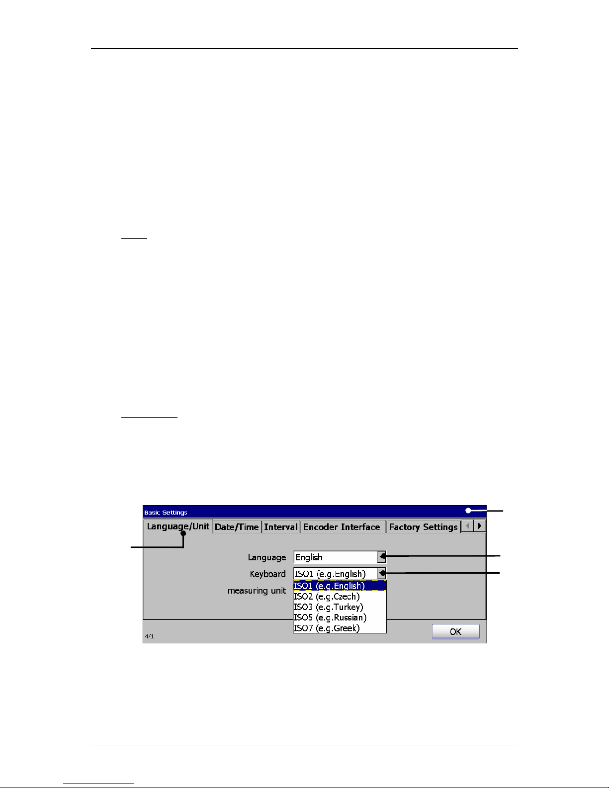
Group 7 Data/Programming Page 75
Release R1.03e LEIBINGER JET3
7.3.1.1 Language and units
The JET3 allows the selection of the operation language, the ISO-fonts which are
assigned to the keyboard as well as the used measuring unit. The parameters which
are set currently are displayed in the pop-up windows.
1. Menu language:
The available menu languages are listed in the pop-up window. The available
languages depend on the ordered version of the printer.
Note:
The function is also helpful to simplify the communication (e.g. in case of
service) with the dealer or the LEIBINGER service-hotline because
English language can be generally selected irrespectively of the
installed language package.
With the selected language the accordant ISO-font is assigned automatically to
the keyboard.
2. Keyboard:
In this Pop-up window you can change preset ISO-fonts with the language
selection.
Annotation:
The allocation of another ISO-font is reasonable e.g. if you have to
create also characters of another language group additionally to the
standard characters of the set language. These characters are then
available in the advanced font of the keyboard.
Figure 34
Set language and keyboard
1 – Menu <Basic settings> 3 – Pop-up window <Language>
2 – Register card <Language/Unit> 4 – Pop-up window <Keyboard>
2
3
1
4
Page 76
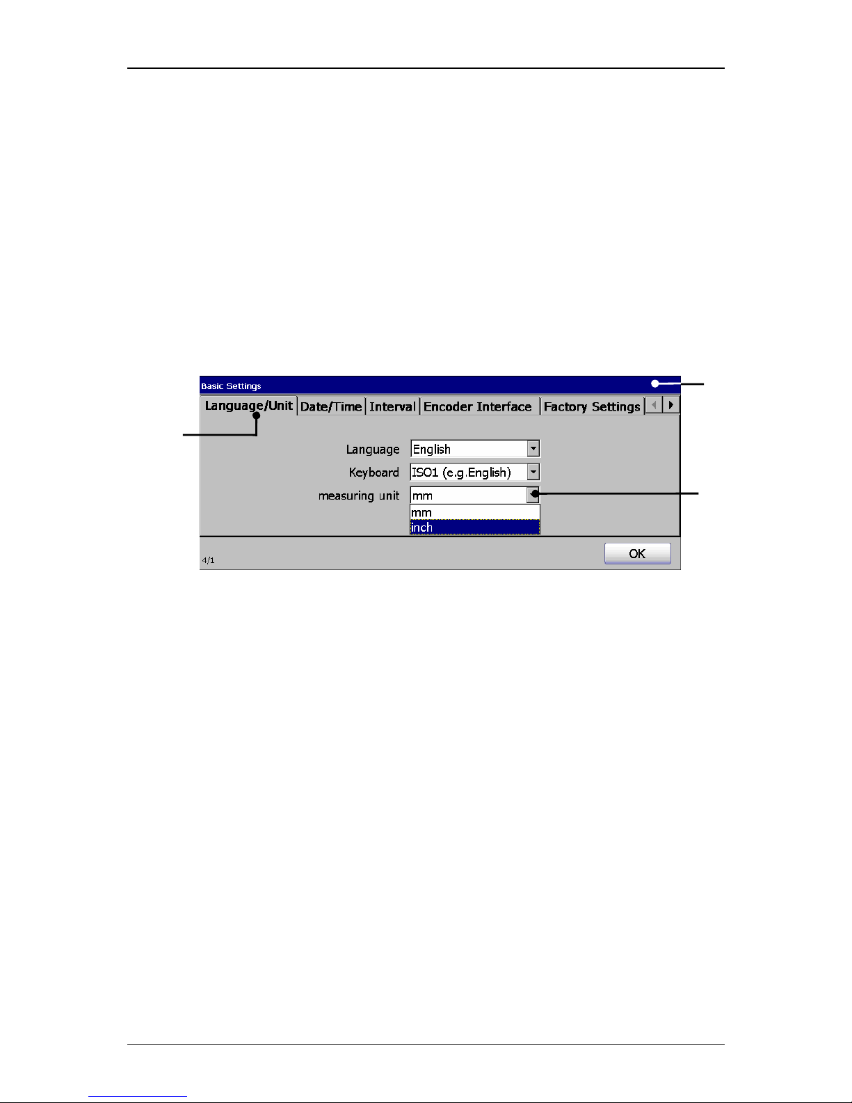
Group 7 Data/Programming Page 76
Release R1.03e LEIBINGER JET3
Proceeding:
Press on the register card <Language/Unit> (2) to select the functional area.
Press on the arrow button of the accordant pop-up window. The pop-up
window opens for selection.
Now select the requested language or the requested keyboard font.
3. Measuring unit:
The two different measuring units „mm“ and „inch“ are available.
Figure 35
Set measuring unit
1 – Menu <Basic Settings> 3 – Pop-up window <Measuring unit>
2 – Register card <Language/Unit>
Proceeding:
Press on the register card <Language/Unit> (2) to select the functional area.
Press on the arrow button of the pop-up window <Measuring unit> (3). The
pop-up window opens for selection.
Now select the requested measuring unit.
2
1
3
Page 77
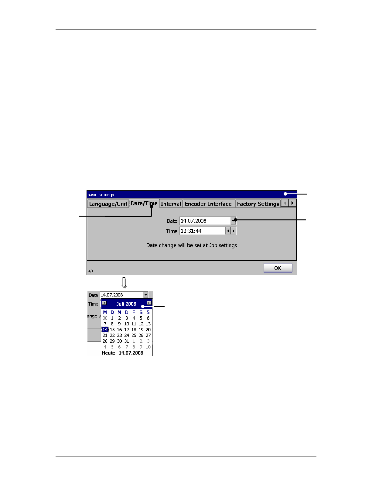
Group 7 Data/Programming Page 77
Release R1.03e LEIBINGER JET3
7.3.1.2 Date and time
Under the register card <Date/Time> you can set the current time and date.
1. Date:
Proceeding:
Press on the register card <Date/Time> (2) to select the functional area.
Press on the arrow button of the pop-up window <Date> (3). A calendar (4)
opens.
Select the requested date. The calendar will be automatically closed and the
selected date is taken over.
Figure 36
Set date
1 – Menu <Basic Settings> 3 – Pop-up window <Date>
2 – Register card <Date/Time> 4 – Calendar
4
2
1
3
Page 78
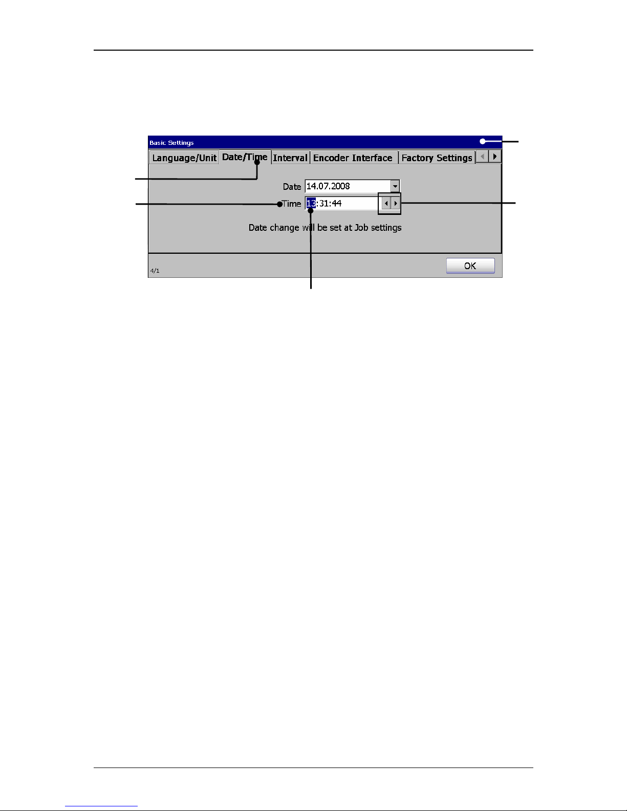
Group 7 Data/Programming Page 78
Release R1.03e LEIBINGER JET3
2. Time:
Figure 37
Set time
1 – Menu <Basic Settings> 4 – Example hour block selected
2 – Register card <Date/Time> 5 – Arrow buttons
3 – Setting field <Time>
Proceeding:
Press on the register card <Date/Time> (2) to select the functional area.
Now mark in the setting field <Time> (3) the hour-, minute- or second block
to change the values.
With the two <Arrow buttons> (5) you can increase or reduce the values of
the blocks wich are each marked.
2
5
1
4
3
Page 79
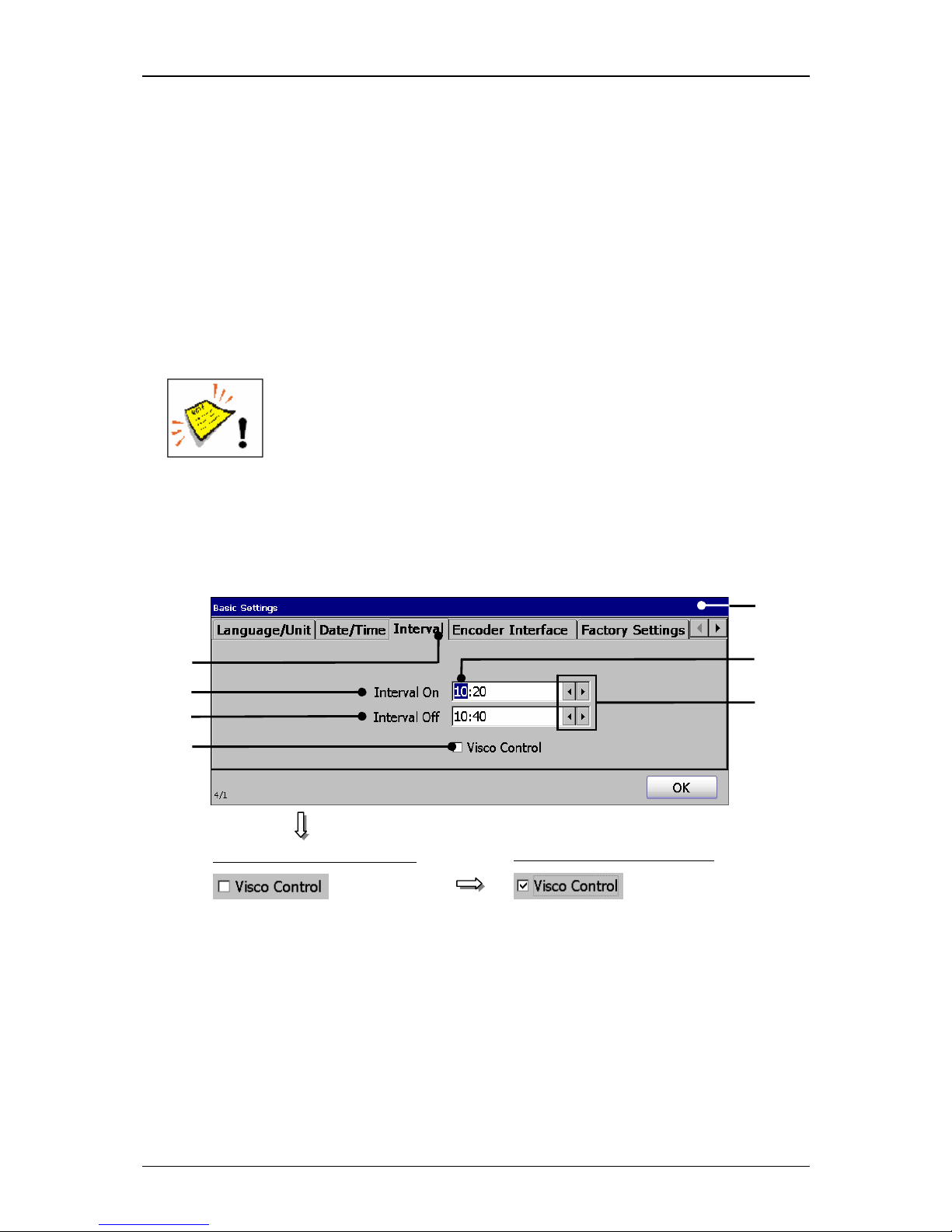
Group 7 Data/Programming Page 79
Release R1.03e LEIBINGER JET3
7.3.1.3 Interval operation (Set interval time)
The mode <Interval operation> enables the input of start-
and end times when the
LEIBINGER JET3 turns on or off automatically (e.g. 10.20 pm, the device turns on /
10.40 pm, the device turns off). to circulate the ink.
This function prevents that the ink dries up or sediments as well as the jamming of
the nozzle if the printer is turned off for a longer time.
As standard the interval operation is carried out without viscosity control. In case of
need the viscosity control can be also activated for the interval operation.
Attention!
The viscosity control should be only activated for special operating
conditions of the JET3 or after consultation with the LEIBINGERservice department.
You should set an interval time of at least 20 minutes.
Figure 38
Interval operation (Set interval time)
1 – Menu <Basic Settings> 5 – Example hour block selected
2 – Register card <Interval> 6 – Arrow buttons
3 – Setting field <Interval On> 7 – Control box <Visco control>
4 – Setting field <Interval Off>
2
4
1
6 3 5
Switched on viscosity control
Switched off viscosity control
7
Page 80

Group 7 Data/Programming Page 80
Release R1.03e LEIBINGER JET3
Proceeding:
Press on the register card <Interval> (2) to select the functional area.
Now mark in the setting field <Interval On> (3) the hour-
or minute block to
change the values.
With the the two <Arrow buttons> (6) you can increase or reduce the blocks
wich are each marked.
Now carry out the settings in the field <Interval (Off> (4) accordingly.
Now activate if necessary
the viscosity control by clicking on the control box
(7). An activated control is displayed by a √
in the control box.
Page 81
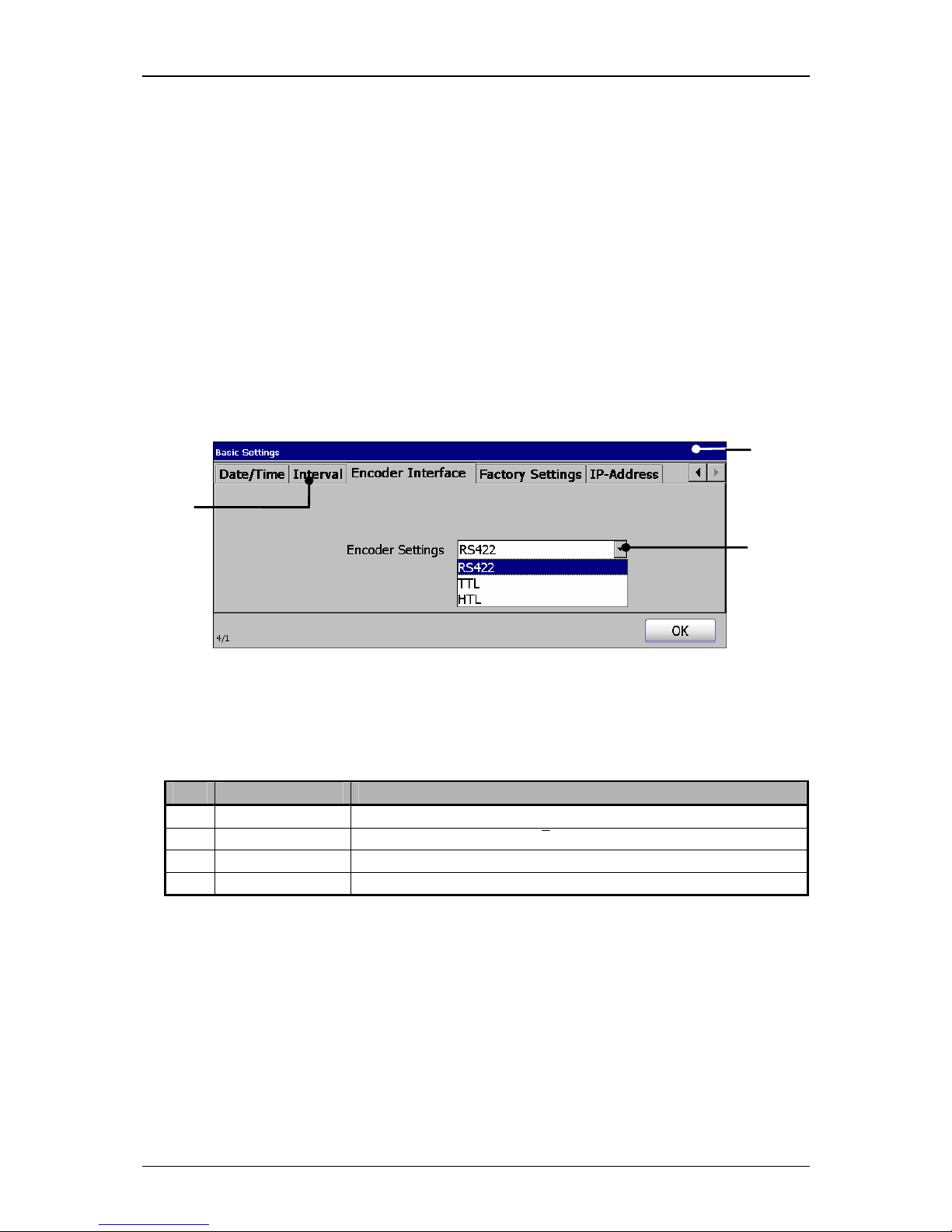
Group 7 Data/Programming Page 81
Release R1.03e LEIBINGER JET3
7.3.1.4 Encoder interface
Under the register card <Encoder Interface>
you can define the incremental
encoder.
Proceeding:
Press on the register card<Encoder Interface> (2) to select the functional area.
Press on the arrow button of the pop-up window <Encoder settings> (3). The
pop-up window opens for selection.
Now select the required interface.
Figure 39
Select encoder interface
1 –Menu <Basic Settings> 3 – Pop-up window <Encoder settings>
2 –Register card <Encoder Interface>
Pos. Interface Describtion
1. RS422 5V / 4 Signals (A, Ā, B, B)
2. TTL 5V TTL / 2 Signals (A, B)
3. HTL 24V / 2 Signals (A, B)
2
1
3
Page 82
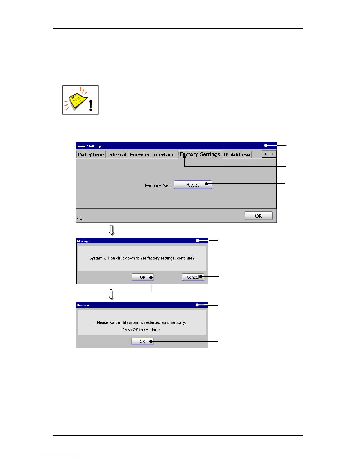
Group 7 Data/Programming Page 82
Release R1.03e LEIBINGER JET3
7.3.1.5 Factory Settings
Under the register card <Factory settings>
you can reset the printer adjustments
to the standard settings.
The consequences of resetting to the factory settings should be
considered!
Figure 40
Reset device to factory settings
1 – Menu <Basic Settings> 5 – Button <Cancel>
2 –Register card <Factory Settings> 6 – Button <OK>
3 –Button <Reset> 7 – Message <Restart>
4 – Safety query <Continue> 8 – Button <OK>
4
2
1
3
6
5
7
8
Page 83

Group 7 Data/Programming Page 83
Release R1.03e LEIBINGER JET3
Proceeding:
Press on the register card <Factory Settings> (2) to select the functional area.
Press the button <Reset> (3).
A Safety query (4) if you would like to continue with the process is faded in.
Press the button <Cancel> (5) to abort the process or press the button <OK>
(6) to reset the device.
The message <Restart> (7) is faded in.
Press the button <OK> (8). The device is shut down automatically and will be
rebooted afterwards. After this process the JET3 is reset to the standard
settings.
Page 84

Group 7 Data/Programming Page 84
Release R1.03e LEIBINGER JET3
7.3.2 Password settings and user authorizations
The LEIBINGER JET3 offers different access levels which are protected by
passwords from faulty operation or non-authorized access. Five levels of access
authorization are available. For each level any functions can be enabled or blocked
to apply access rights for e.g. operator or supervisor (free definable).
7.3.2.1 Menu password settings
With the option <Password Settings> (2) the menu „Password settings“ (3) opens.
This menu provides
Selection of user levels (Level of access right)
Definition of access rights.
Definition of passwords
In the several functional areas you can enable or lock the functions in the current
access levels. An enabled function is displayed by a √
in the accordant control box.
The selection of a functional area happens by clicking on the accordant register card
(4).
Note:
The proceeding corresponds to the Windows™-standard procedure.
With the pop-up window <Level>
(5) you can select the user levels for which you
would like to carry out the settings.
In the input field <Password> (6) you can enter the password for the current user
level or you can display an already defined password.
With the button <set…> (7) the password which has been entered for the current
access level will be taken over.
With the button <OK> (8) the menu closes and the settings will be saved.
The button <Cancel> (9) closes the menu without taking over the carried out
changes.
Page 85
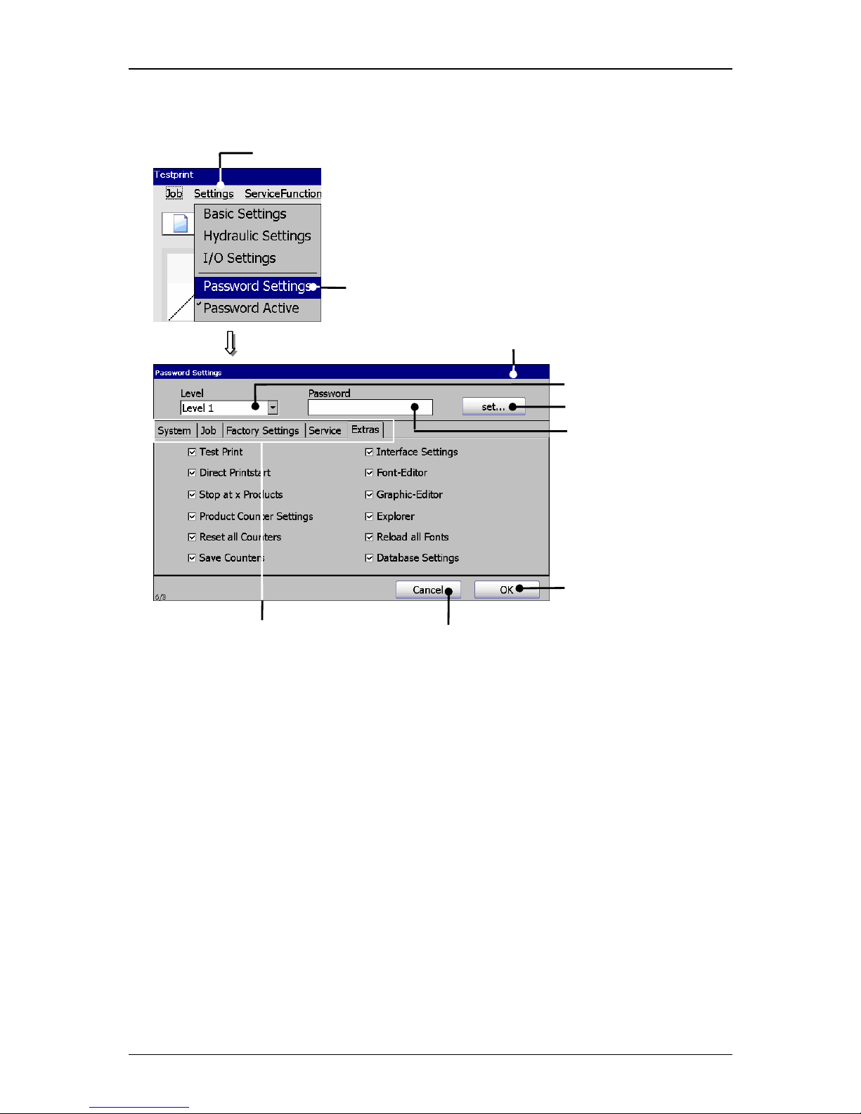
Group 7 Data/Programming Page 85
Release R1.03e LEIBINGER JET3
Figure 41
Menu password settings
1 – Button <Settings> 6 – Input field <Password>
2 – Option <Password Settings> 7 – Button <set…>
3 – Menu <Password Settings> 8 – Button <OK>
4 – Register cards 9 – Button <Cancel>
5 – Pop-up window <Level>
Proceeding:
Press the button <Settings> (1) and the option <Password Settings> (2).
The menu <Password Settings> (3) is faded in.
1
2
6 8
3
7
9 4 5
Page 86
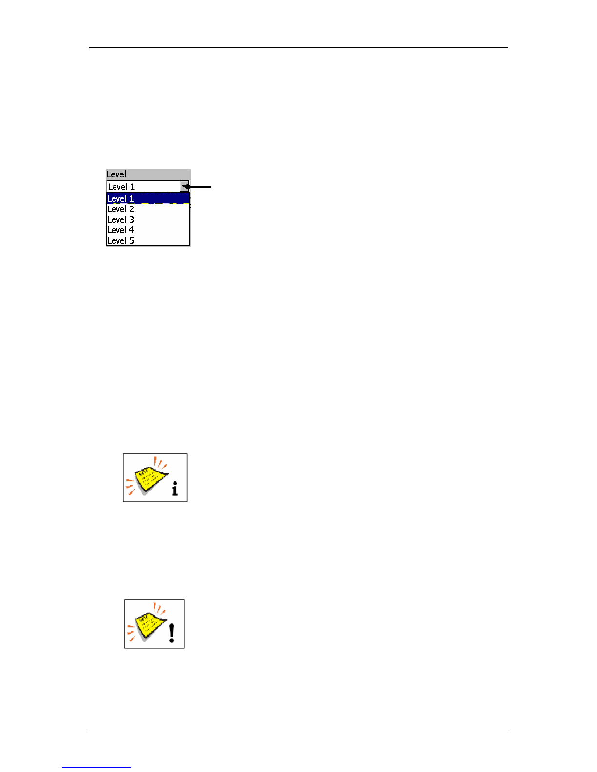
Group 7 Data/Programming Page 86
Release R1.03e LEIBINGER JET3
7.3.2.1.1 Selection of user level (Level of access authorization)
With the pop-up window <Level>
(1) you can select the user level for which the
user rights should be activated as well as how the password should be defined.
Figure 42
Selection of user level (Level of access authorization)
1 – Pop-up window <Level>
7.3.2.1.2 Definition of password
In the input field <Password>
(1) you can enter the password for the current user
level or you can display an already defined password.
Proceeding:
Example: The password „Leibinger“ should be defined.
Click in the input field <Password> (1). A keyboard field (2) opens for input.
You will find further information regarding the operation with
keyboard fields in the Chapter Keyboard field!
Enter the password „Leibinger“. The input is displayed in the input field
<Password> (1).
Press the button <Enter> (3) of the keyboard field to finish the input.
Now press the button <set…> (4) to take over the entered password.
Attention! A final taking over does only happen if the menu is
closed with the button <OK>!
1
Page 87
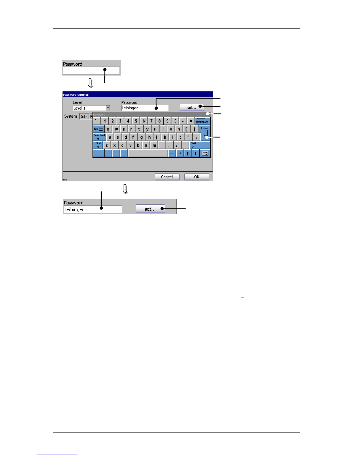
Group 7 Data/Programming Page 87
Release R1.03e LEIBINGER JET3
Figure 43
Define password
1 – Input field <Password> 3 – Button <Enter>
2 – Keyboard field 4 – Button <set…>
7.3.2.1.3 Definition of user rights
In the several functional areas of the menu you can enable or lock the functions of
the current access levels. An enabled function is displayed by a √
in the control box.
The selection of a functional area happens by clicking on the accordant register
card.
Note:
The proceeding corresponds to the Window™-standard procedure.
7.3.2.2 Lost password
If the password of the highest defined access right (Supervisor) has been lost
special measures are required. In this case please contact the dealer address which
is listed in the chapter Editor.
1
1
4
4
1
3
2
Page 88
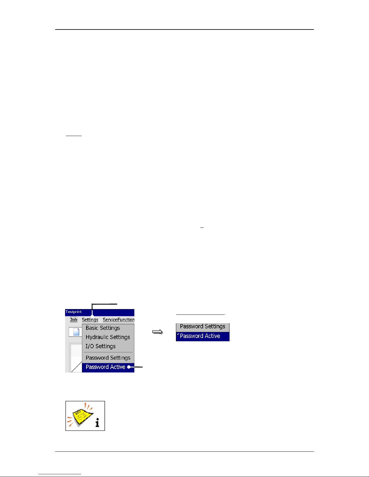
Group 7 Data/Programming Page 88
Release R1.03e LEIBINGER JET3
7.3.3 Password protection (Password query)
If the password protection LEIBINGER JET3 is activated a password enquiry is
carried out for every start of the device.
Further more the function <Login>
in the menu „Extras“ is activated. With this
function an user can login during the operation to e.g. carry out functions which are
still not enabled and can logout and can therefore prevent changes of the settings
by unauthorized staff.
Note:
If no password has been entered for an activated password query during
starting the device, only the following basic functions are available for
the user.
Open and close nozzle
Print start and print stop
Login
Touch-Calibration
After logout of the user these basic functions are still only available.
If the function is activated it is displayed by a √
on the control box of the function.
The function is activated or deactivated as following:
Press the button <Settings> (1) and the option <Password Activate> (2).
The function is activated or deactivated depending on the existing status.
Figure 44
Activate/deactivate password query
1 – Button <Settings> 2 – Option <Password protection activated >
You will find further information regarding login/logout and switching
on the device in the chapters Login and Switching on with password
protection!
1
2
Function activated
Page 89
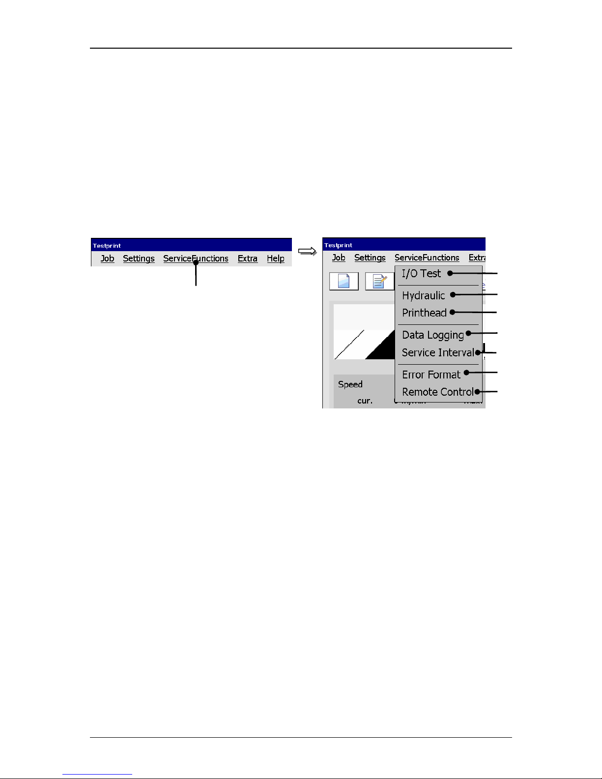
Group 7 Data/Programming Page 89
Release R1.03e LEIBINGER JET3
7.4 Service functions
With the button <ServiceFunctions> in the main menu bar the submenu „Service
functions“ is displayed. The following options are available:
I/O-Test Hydraulic Printhead
Data Logging Service Interval Error Format
Remote Control
Figure 45
Menu Service functions
1 – Button <ServiceFunctions> 5 – Option <Data Looging (Protocol file)>
2 – Option <I/O Test> 6 – Option <Service Interval>
3 – Option <Hydraulic> 7 – Option <Error Format>
4 – Option <Printhead> 8 – Option <Remote Control>
1
2
3
4 5 6 7 8
Page 90
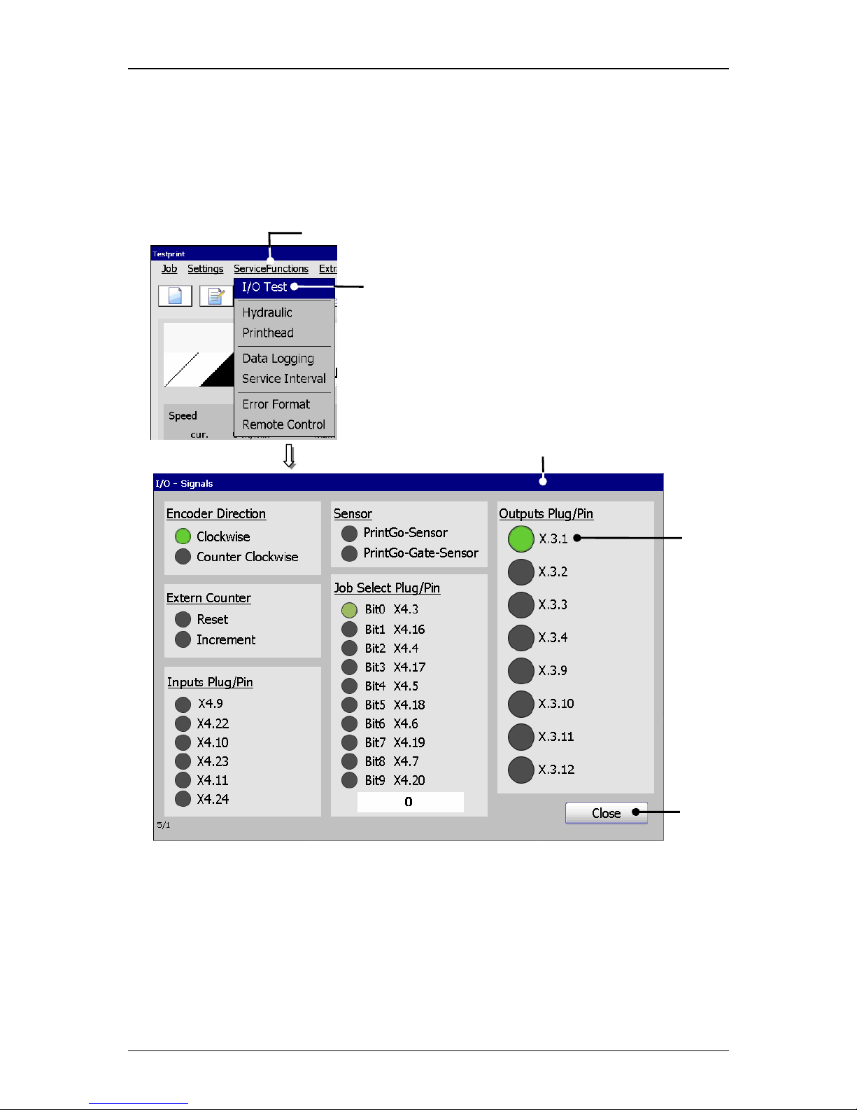
Group 7 Data/Programming Page 90
Release R1.03e LEIBINGER JET3
7.4.1 I/O Test (Signaltest)
With the option <I/O Test> (2) the menu „I/O-Signals (3)“ is displayed. The menu
shows the states of the inputs and outputs of the device.
Figure 46
5
I/O-Signal test
1 – Button <ServiceFunctions> 4 – Status display <I/O active/inactive>
2 – Option <I/O-Test> 5 – Button <Close>
3 – Menu <I/O-Signals>
The button <Close> (5) ends the menu.
1
2
5
4
3
Page 91

Group 7 Data/Programming Page 91
Release R1.03e LEIBINGER JET3
The menu allows to carry out a temporary test of the inputs and outputs of the
LEIBINGER JET3 during the troubleshooting without any additional tools.
If signals are fed to the inputs the signal status are displayed in the menu. The
functions which are assigned to the inputs are not carried out for feeding the
signals!
Active in-/outputs are displayed by a green status display.
For leaving the menu all carried out settings will be rejected, that means if outputs
have been defined just for testing (activated) they will be deactivated again.
Page 92
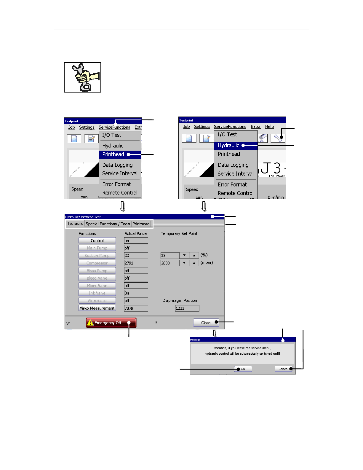
Group 7 Data/Programming Page 92
Release R1.03e LEIBINGER JET3
7.4.2 Hydraulic-/Printhead – and special functions
This work must only be carried out by trained personnel or by
Leibinger service technicians!
Figure 47
Hydraulic/Printhead test menu
1 – Direct button (Icon) <Service> 7 – Button <Close>
2 – Button <ServiceFunctions> 8 – Register cards
3 – Option <Printhead> 9 – Message <Close menu>
4 – Option <Hydraulic> 10 – Button <OK>
5 – Menu <Hydraulic/Printhead Test> 11 – Button <Cnacel>
6 – Button <Emergency Off>
2
3
7
6
5
1
4
oder
8
1
0
11
9
Page 93

Group 7 Data/Programming Page 93
Release R1.03e LEIBINGER JET3
By pressing the direct button [icon] <Service>
(1) or with the options
<Printhead> (3) or <Hydraulic>
(4) you can open the menu „Hydraulic/Printhead
Test“ (5).
This menu provides the verification of hydraulic components, activation or
deactivation and setting of print head functions as well as the processing of special
functions. All changes have only a temporary effect, that means as long as the
menu is open.
The selection of a functional area happens by clicking on the accordant register card
(8).
Note:
The proceeding corresponds to the Windows™-standard procedure.
By pressing the button <Emergency off>
(6) the JET3 is turned off immediately,
without carrying out further actions (e.g. closing the nozzle).
The button <Close> (5) closes the menu.
By closing the menu all changes are reset to the normal/fully
automatic operating condition!
If the menu closes an accordant message (9) is faded in which can
confirm or cancel the quitting.
Page 94
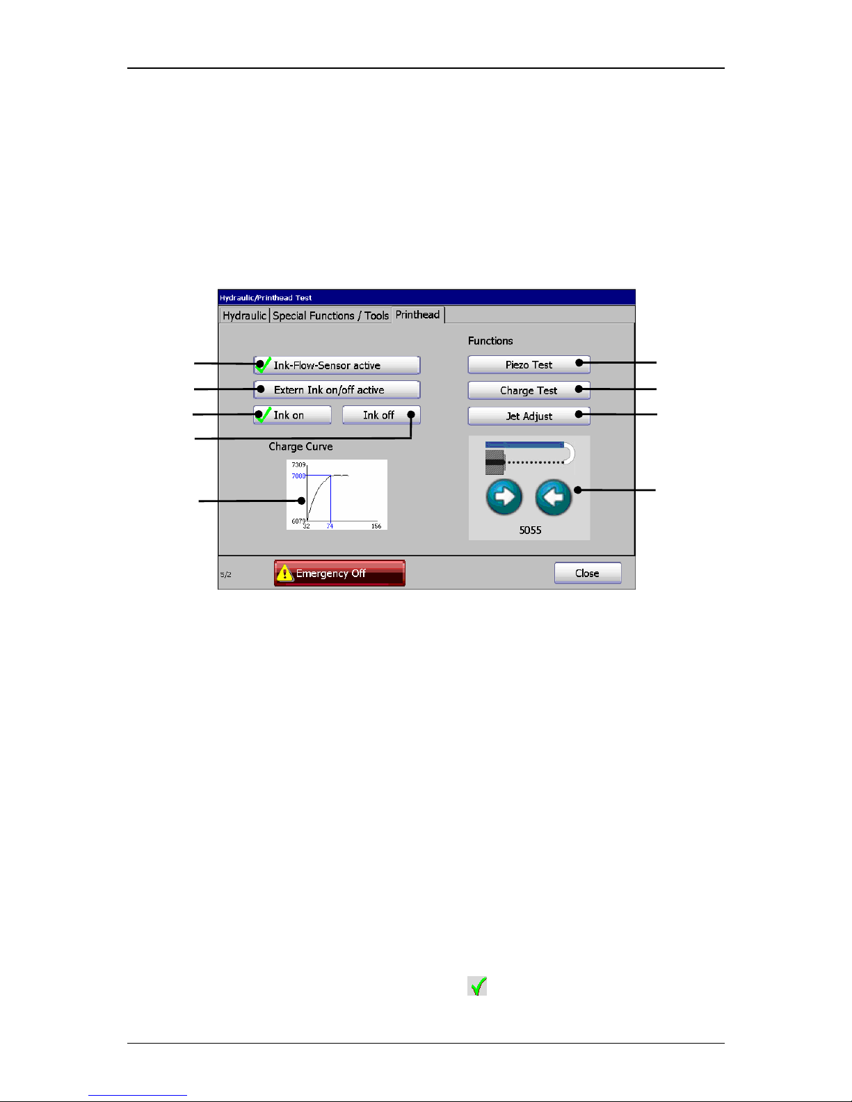
Group 7 Data/Programming Page 94
Release R1.03e LEIBINGER JET3
7.4.3 Printhead functions
Under the register card <Print head> the following functions are available:
Ink-Flow-Sensor active Ink on/Ink off Charge Test
Extern Ink on/off active Piezo Test Jet Adjust
Figure 48
Register card printhead
1 – Button <Ink-Flow-sensor active> 6 – Button <Charge Test>
2 – Button <Ink on> 7 – Button <Jet Adjust>
3 – Button <Ink off> 8 – Operating field<Nozzle seal>
4 – Button <Extern Ink on/off active> 9 – Display <Charging voltage curve>
5 – Button <Piezo Test>
7.4.3.1 Jet monitoring (Ink-Flow-Sensor active)
The ink jet monitoring provides highest operating reliability due to the additional
monitoring of the ink backflow. The full automatic monitoring turns off the ink jet as
soon as the ink backflow is interrupted. The nozzle seal will be closed automatically
and head impurities are therefore prevented.
By pressing the button <Ink-Flow-Sensor active>
(1) the jet monitoring is turned
on or off.
An activated jet monitoring is designated by a on the button.
3
1
4
2
5
6
7
8
9
Page 95
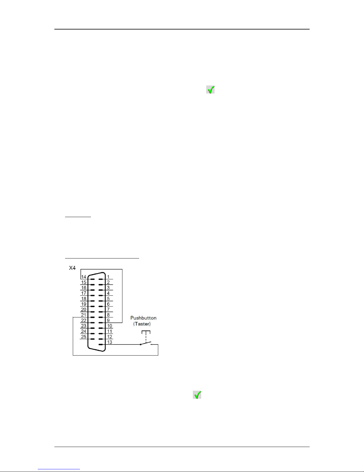
Group 7 Data/Programming Page 95
Release R1.03e LEIBINGER JET3
7.4.3.2 Ink on/off
With the two buttons <Ink on > (2) and <Ink off >
(3) the ink delivery to the
nozzle is turned on or off.
The status of the ink delivery is designated by a on the accordant button.
This function can be generated also „remote-controlled“ by an electronical contact
(see also the informations in the following chapter).
7.4.3.3 Extern Ink on/off
During cleaning works at the print head it can be helpful (e.g. in case of a long
umbilical) that the ink delivery can be turned on/off externally. The JET3 requires
impulses for the control.
This can be reached with a bridge between pin 9 and 14 and a switch contact
(pushbotton) at the pins 21 and 13 of the I/O interface X4.
Example:
First impulse = switches off the ink delivery
Second impulse = switches on again the ink delivery
Diagram/Plug assignment:
The signal which is pending at the interface is only analyzed by the JET3 if the
function <Extern Ink on/off active> (4) is turned on.
If the function is activated, it is shown by a on the display.
Page 96
Group 7 Data/Programming Page 96
Release R1.03e LEIBINGER JET3
7.4.3.4 Piezo test and charge test
You will find further informations in the separate document Service
manual!
7.4.3.5 Jet adjustment
This function provides a support for a required correction of the jet position.
This work must only be carried out by trained personnel or by
Leibinger service technicians!
Required tools and facilities:
Magnifier (Sixfold lens)
Allen key 1,5 mm
Attention! Do not use a ball head-Allen key because it can cause
damages at the screw heads!
Turn on the JET3 by touching the dark touch-display
(1) at any position
(Duration of touching approx. 2 sec.)
.
The main menu (2) with the message <Initialization> (3) is displayed.
After initialization the device starts automatically with the bleeding of the
system. During the process the message <Bleeding> (4) is displayed.
Wait until the bleeding process is finished.
Note:
Do not cancel the bleeding cycle ahead of time!
Press the button <ServiceFunctions> (1) and the option <Printhead> (2).
or
Press the Icon <Service> (7) and the register card <Printhead> (8).
The functional area <Printhead>
(9) in the menu „Hydraulic/ Print head Test“ is
now displayed.
Now turn off the jet monitoring with the button <Ink-Flow-Sensor active> (10).
An activated jet monitoring is marked by a …… on the button
Remove the print head cover (11).
Page 97
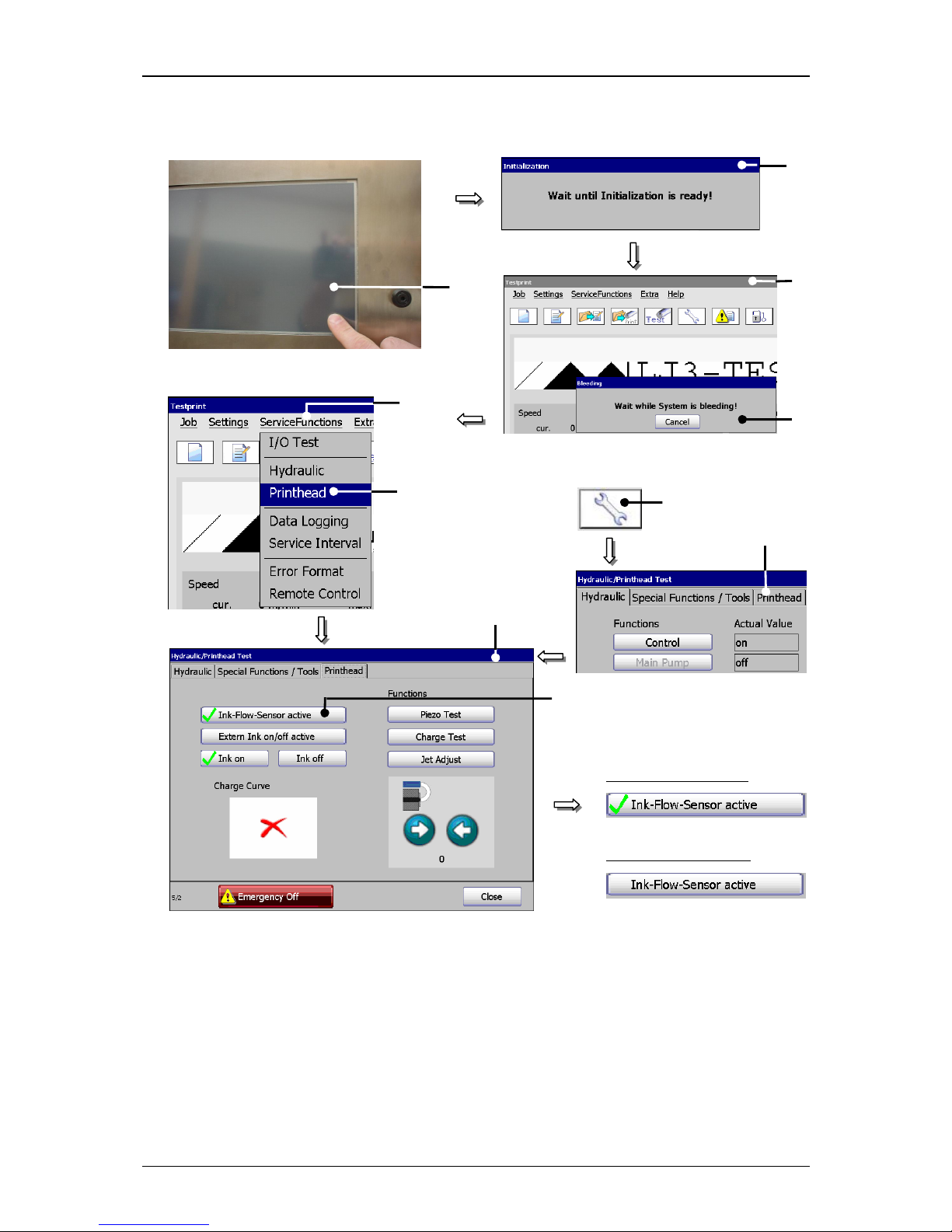
Group 7 Data/Programming Page 97
Release R1.03e LEIBINGER JET3
Figure 49
Jet adjustment (setp 1)
1 – TFT-Touch-Display 6 – Option <Printhead>
2 – Message <Initialization> 7 – Direct button (Icon) <Service>
3 – Main menu 8 – Register card <Printhead>
4 – Message <Bleeding> 9 – Functional area <Printhead>
5 – Button <ServiceFunctions> 10 – Button <Ink-Flow-Sensor active>
5
6
1
0
5
7
8
or
Monitoring turned off
1
3
2
4 9
Monitoring turned on
Page 98
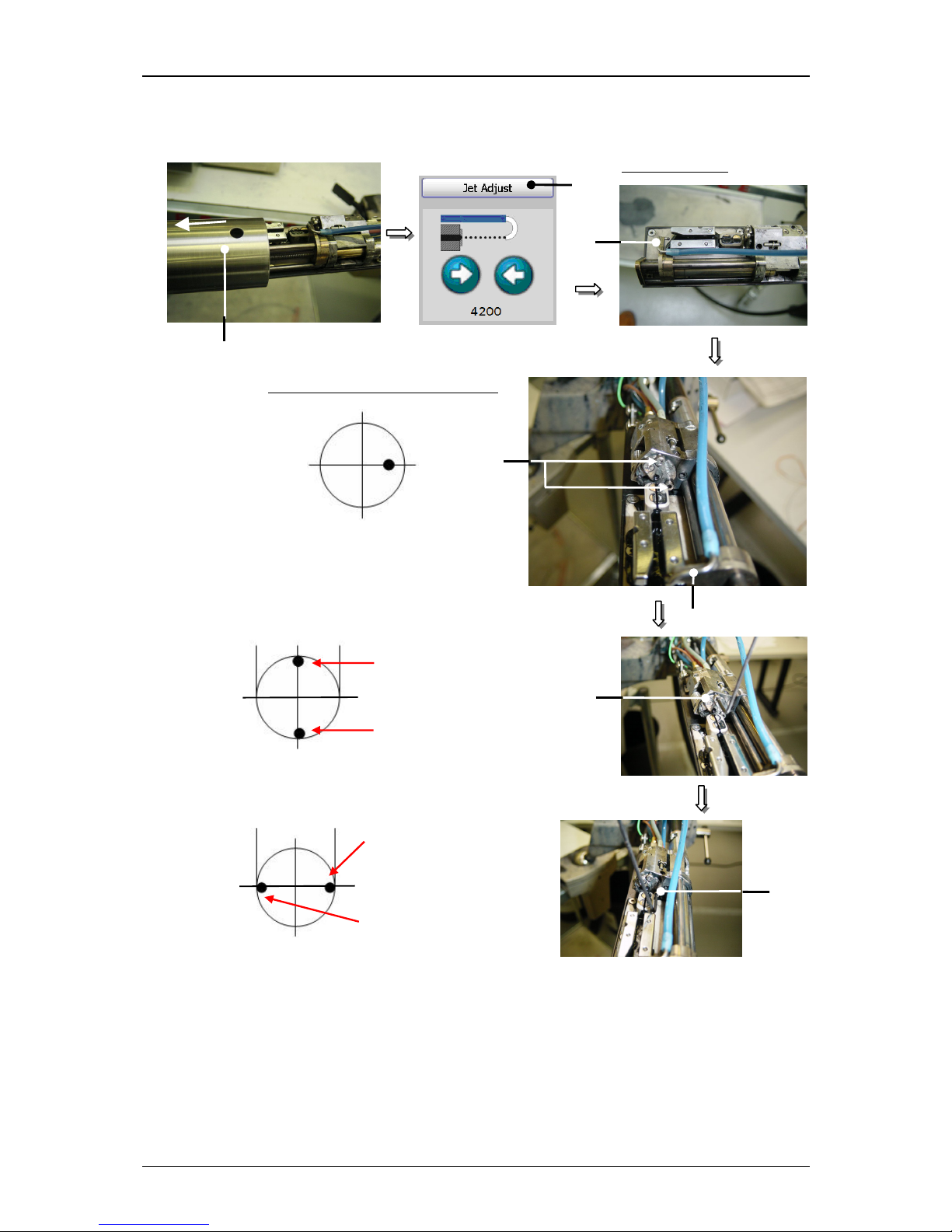
Group 7 Data/Programming Page 98
Release R1.03e LEIBINGER JET3
Figure 50
Jet adjustment (Step 2)
11 – Head cover 13.1 – Upper setting screw
12 – Button <Jet Adjust> 13.2 – Lateral setting screw
13 – Setting screw (2x) 14 – Gutter tube
Setting position
11
Gutter tube top edge
12
Setting position in the gutter tube
14
14
13.1
13
13.2
Gutter tube bottom edge
Right gutter tube angle
Left gutter tube angle
Page 99

Group 7 Data/Programming Page 99
Release R1.03e LEIBINGER JET3
Press the button <Jet Adjust>
(12). The gutter motor of the print head is now
moving automatically to the required setting position (approx. 4200).
Note:
Smaller deviations from the given setting position are in the tolerance
range of the system!
The ink jet has to be now adjusted with the two setting screws 13) according to
the following picture (jet adjustment (step2)) to the gutter tube (14).
By turning the upper setting screw (13.1) clockwise the ink jet moves to the
direction of the gutter tube top edge. Counter-clockwise the jet moves to the
direction of the gutter tube bottom edge.
Note:
Line of sight from the nozzle to the gutter tube.
By turning the lateral setting screw (13.2) clockwise the ink jet moves to the
direction of the left gutter tube angle. Counter-clockwise the jet moves to the
direction of the right gutter tube angle.
Note:
Line of sight from the nozzle to the gutter tube.
After carried out adjustment of the jet position in the gutter tube the complete
jet generation unit has to be adjusted in the charging tunnel (15) and in the
deflection plates in this way that the ink jet is parallel and flush with the left
angle of the charging tunnel.
Note:
Line of sight from the nozzle to the gutter tube.
Attention! The ink jet should be absolutely parallel to the
deflection plates.
For the optical evaluation of the jet position it is important that the
angle of view is exactly adjusted vertically from above via the
charging tunnel and ink jet to exclude parallax errors as far as
possible.
Setting sequence:
1. Open the 5 locking screws on the fixing plate (17) as far as the unit can be
moved by hand.
2. Move the unit carefully until the ink jet corresponds with the shown setting
position.
3. Fix the settings by tighten the locking screws (17).
4. Check the setting positions after fixing again and if necessary correct the
position again.
Now the nozzle seal has to be opened completely to souse the ink jet completely
into the charging tunnel (15). For this press on the arrow button <Open
nozzle> (18) and keep it pressed until the gutter motor has reached it’s end
position.
Page 100
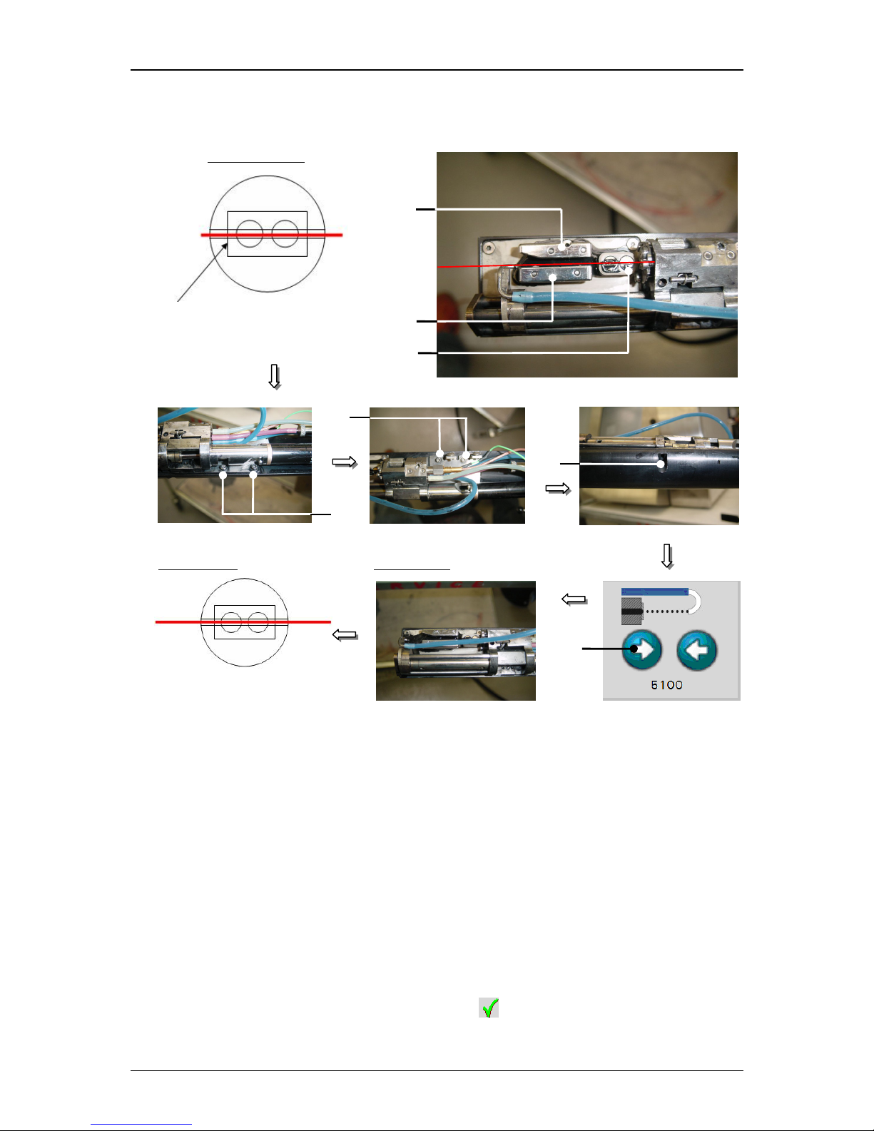
Group 7 Data/Programming Page 100
Release R1.03e LEIBINGER JET3
Figure 51
Jet adjustment (Step 3)
15 – Charging tunnel 17 – Holding screw of the fixing plate (5x)
16 – Deflection plates 18 – Arrow button <Open nozzle>
In this position check the setting position again. The ink jet should be now in the
centre of the charging tunnel and parallel to the deflection plates. If necessary
the position has to be corrected again by moving the fixing plate.
If you have reached the correct setting you have to close the nozzle seal. For
this press on the arrow button <Close nozzle>
(19) and keep it pressed until
the nozzle seal is completely closed.
Finally activate the ink jet monitoring with the button <Ink-Flow-Sensor active>
(20).
An activated jet monitoring is marked by a … on the button.
Close the menu with the button <Close> (21).
Setting position
17
17
Left angle of charging tunnel
17
16
15
16
18
End position
Target result
 Loading...