


16.4 oz Propane Bottle
Not Included
WARNING:
THE ENGINE EXHAUST FROM THIS
PRODUCT CONTAINS CHEMICALS
KNOWN TO THE S
TATE OF CALIFORNIA
TO CAUSE CANCER, BIRTH DEFECTS
OR OTHER REPRODUCTIVE HARM.
OPERATOR’S MA
PROPANE POWERED LINE TRIMMER
ECO-TRIMMER
NUAL
TABLE OF CONTENTS
Service and Safety ............................................................. 2
Safe Operation Rules .......................................................... 3
Understanding Your Trimmer ............................................... 4
Assembly ........................................................................... 5
Oil Information .................................................................... 6
Understanding Propane ...................................................... 7
Installing the Propane Canister ............................................ 8
Installing Attachments ......................................................... 9
Starting / Stopping ........................................................... 10
Operation ......................................................................... 11
Maintenance .................................................................... 12
Cleaning and Storage ....................................................... 19
Troubleshooting ................................................................ 19
Speci¯cations .................................................................. 20
Warranty .......................................................................... 21
MODELS:
ST 025SS
ST 025
DC
ST 025CS
ST 025
DO NOT RETURN THE UNIT
TO THE RETAILER
Call 1-866-941-LEHR (5347)
DS
LEHR | ALL RIGHTS RESERVED 2008-2009

LEHR |
2
WARNING:
WHEN USING THE UNIT, YOU MUST
FOLLOW THESE SAFETY RULES. PLEASE
READ THESE TO ENSURE THE SAFETY OF
THE OPERATOR AND ANY BY ST ANDERS.
PLEASE KEEP THESE INSTRUCTIONS FOR
LATER USE.
WARNING:
WHEN SERVICING, USE ONLY
REPLACEMENT
IDENTICAL
PARTS. USE OF ANY OTHER
PARTS
MAY CREATE A HAZARD OR CAUSE
PRODUCT DAMAGE.
SERVICE AND SAFETY
SAFE OPERATION RULES
LEHR ECO-TRIMMER
4-CYCLE PROPANE TRIMMER
For service call 1-866-941-LEHR in the United States, to
obtain a list of authorized service dealers near you.
For more details about your unit, visit our website at:
www.golehr.com.
DO NOT RETURN THE UNIT TO THE RETAILER.
PROOF OF PURCHASE WILL BE REQUIRED FOR
WARRANTY SERVICE.
THIS PRODUCT IS COVERED BY ONE OR MORE
U.S. PATENTS. OTHER PATENTS ARE PENDING
Service on this unit both within and after the warranty
period should be performed only by an authorized and
approved service dealer.
SPARK ARRESTOR NOTE
NOTE: For users on U.S. Forest Land and in the states
of California, Maine, Oregon, and Washington. All U.S.
Forest Land and the State of California (Public Resources
Codes 4442 and 4443), Oregon, and Washington require
by law that certain internal combustion engines operated
on forest brush and/or grass-covered areas be equipped
with a spark arrestor, maintained in eective working order,
or the engine be constructed, equipped and maintained
for the prevention of re. Check with your state or local
authorities for regulations pertaining to these requirements.
Failure to follow these requirements could subject you to
liability or a ne. This unit is factory equipped with a spark
arrestor.
All information, illustrations, and specications in this
manual are based on the latest production information
available at the time of printing. We reserve the right to
make changes at any time without notice.
IMPORTANT SAFETY INSTRUCTIONS
READ ALL INSTRUCTION BEFORE OPERATING
• Inspect the unit before use. Replace damaged parts.
• Check for fuel leaks. Make sure all fasteners are in place
and secure. Replace parts that are cracked, chipped,
or damaged in any way. Do not operate the unit with
loose or damaged parts.
• Carefully inspect the area before starting the unit.
Remove all debris and hard or sharp objects such as
glass, wire, etc.
• Be aware of the risk of injury to the head, hands and
feet.
• Clear the area of children, bystanders, and pets. At
a minimum, keep all children, bystanders, and pets
outside a 50 feet (15 m.) radius; there still may be a risk
to bystanders from thrown objects. Bystanders should
be encouraged to wear eye protection. If you are
approached, stop the unit immediately.
• Use only original equipment manufacturer replacement
line. Never use metal-reinforced line, wire or rope.
These can break o and become dangerous projectiles.
• Squeeze the throttle control and check that it returns
automatically to the idle position. Make all adjustments
or repairs before using unit.
• Do not operate this unit when tired, ill, under the
inuence of alcohol, drugs or medications.
• This unit is intended for adult use only. Do not allow
children or untrained individuals to use the unit.
• Familiarize yourself with the controls and proper use of
your trimmer prior to using.
DU
• Never start or run the unit inside a closed room or
ing. Breathing exhaust fumes can be fatal. Operate this
unit only in a well ventilated outdoor area.
• Wear safety glasses or goggles that meet ANSI Z87.1
standards and are marked as such. Wear ear/hearing
protection when operating this unit. Wear a face or dust
mask if the operation is dusty.
• Wear heavy long pants, boots, gloves and a long sleeve
shirt. Do not wear loose clothing, jewelry, short pants,
sandals or go barefoot. Secure hair above shoulder
level.
• The cutting attachment shield must always be in place
while operating the unit as a trimmer. Do not oper
ate unit without both trimming lines extended, and the
proper line installed. Do not extend the trimming line
beyond the length of the shield.
• This unit has a clutch. The cutting attachment remains
stationary when the engine is idling. If it does not, have
the unit adjusted by an authorized service technician.
• Adjust the handle to your size in order to provide the
best grip.
• Be sure the cutting attachment is not in contact with
anything before starting the unit.
• Avoid accidental starting. Be in the starting position
whenever pulling the starter rope. The operator and
unit must be in a stable position while starting. Refer to
Starting/Stopping Instructions. (p.10)
• Only use this tool for its intended purpose.
• Do not overreach. Always keep proper footing and bal
ance.
• Always hold the unit with both hands when operating.
Keep a rm grip on both handles or grips.
• Keep hands, face, and feet at a distance from all mov
ing parts. Do not touch or try to stop the cutting attach
ment when it rotates.
ALL RIGHTS RESERVED 2008-2009
parts get extremely hot from operation, even after the
unit is turned o.

LEHR | ALL RIGHTS RESERVED 2008-2009
3
SAFE OPERATION RULES
DURING OPERATION
• Never start or run the unit inside a closed room or build
ing. Breathing exhaust fumes can be fatal. Operate this
unit only in a well ventilated outdoor area.
• Wear safety glasses or goggles that meet ANSI Z87.1
standards and are marked as such. Wear ear/hearing
protection when operating this unit. Wear a face or dust
mask if the operation is dusty.
• Wear heavy long pants, boots, gloves and a long sleeve
shirt. Do not wear loose clothing, jewelry, short pants,
sandals or go barefoot. Secure hair above shoulder
level.
• The cutting attachment shield must always be in place
while operating the unit as a trimmer. Do not oper -
ate unit without both trimming lines extended, and the
proper line installed. Do not extend the trimming line
beyond the length of the shield.
• This unit has a clutch. The cutting attachment remains
stationary when the engine is idling. If it does not, have
the unit adjusted by an authorized service technician.
• Do not operate the engine faster than the speed needed
-
to cut, trim or edge. Do not run the engine at high speed
when not cutting.
• Always stop the engine when cutting is delayed or when
walking from one cutting location to another.
• If you strike or become entangled with a foreign object,
stop the engine immediately and check for damage. Do
not operate before repairing damage. Do not operate the
unit with loose or damaged parts. Stop the unit, switch
the engine to o, and disconnect the spark plug for
maintenance or repair.
• Use only original equipment manufacturer replacement
parts and accessories for this unit. These are available
from your authorized service dealer. Use of any unau thorized parts or accessories could lead to serious injury
to the user, or damage to the unit, and void your war ranty.
• Keep unit clean of vegetation and other materials. They
may become lodged between the cutting attachment
and shield.
• Adjust the handle to your size in order to provide the
best grip.
• Be sure the cutting attachment is not in contact with
anything before starting the unit.
• Use the unit only in daylight or good artificial light.
• Avoid accidental starting. Be in the starting position
whenever pulling the starter rope. The operator and
unit must be in a stable position while starting. Refer to
Starting/Stopping Instructions. (p.10) .
• Only use this tool for its intended purpose.
• Do not overreach. Always keep proper footing and bal ance.
• Always hold the unit with both hands when operating.
Keep a firm grip on both handles or grips.
• Keep hands, face, and feet at a distance from all mov
ing parts. Do not touch or try to stop the cutting attach ment when it rotates.
• Do not touch the engine, gear housing or muffler. These
parts get extremely hot from operation, even after the
unit is turned o.
To reduce fire hazard, replace faulty muffler and spark
arrestor. Keep the engine and muffler free from grass,
leaves, excessive grease or carbon build up.
OTHER SAFETY WARNINGS
• Never store a unit with propane canister attached inside
a building where vapor may reach an open flame or
spark.
• Allow the engine to cool before storing or transporting.
Be sure to secure the unit while transporting.
• Store the unit in a dry area, locked up or up high to
prevent unauthorized use or damage, out of the reach of
children.
• Never douse or squirt the unit with water or any other
liquid. Keep handles dry, clean and free from debris.
Clean after each use, see Cleaning and Storage instruc -
-
tions. (p.19)
• Keep these instructions. Refer to them often and use
them to instruct other users. If you loan someone this
unit, also loan them these instructions.
SAVE THESE INSTRUCTIONS
LEHR | ALL RIGHTS RESERVED 2008-2009
4
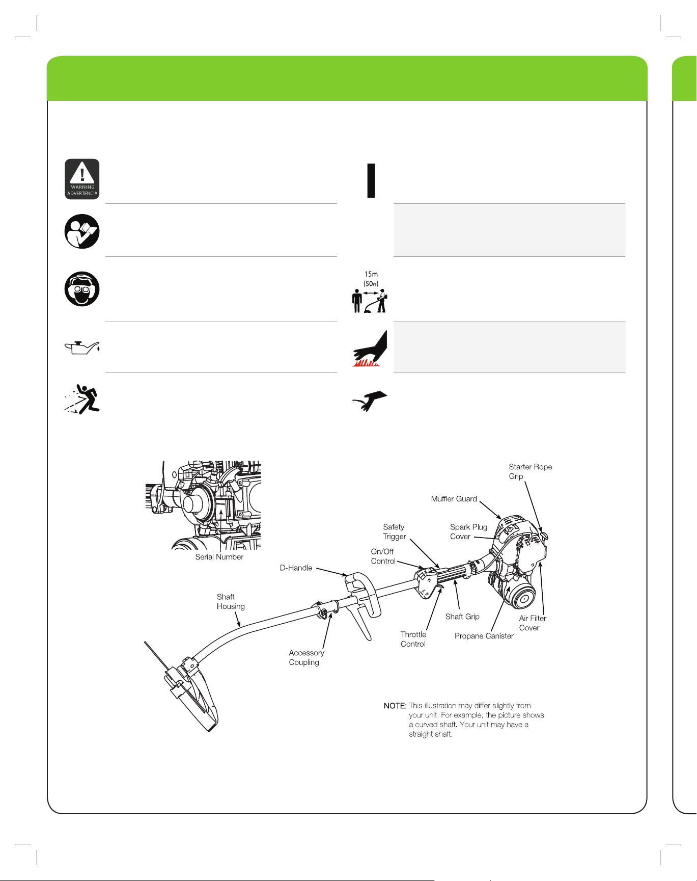
UNDERSTANDING YOUR TRIMMER
SAFETY AND INTERNATIONAL SYMBOLS
This operator’s manual describes safety and international symbols and pictographs that may appear on this product.
Read the operator’s manual for complete safety, assembly, operating and maintenance and repair information.
WARNING: Indicates danger, warning or caution.
May be used in conjunction with other symbols or
pictographs.
WARNING: READ OPERATOR’S MANUAL:
Read the operator’s manual(s) and follow all warnings
and safety instructions. Failure to do so can result in
serious injury to the operator and/or bystanders.
WEAR EYE AND HEARING PROTECTION WARNING:
Thrown objects and loud noise can cause severe eye
injury and hearing loss. Wear eye protection meeting
ANSI Z87.1 standards and ear protection when
operating this unit. Use a full face shield when needed.
OIL : Refer to operator’s manual for the proper type of oil.
ON/OFF STOP CONTROLS ON/START/RUN
ON/OFF STOP CONTROL OFF or STOP
KEEP SYSTANDERS AWAY WARNING:
Keep all bystanders, especially children and pets, at
least 50 feet (15 m) from the operating area.
HOT SURFACE WARNING
Do not touch a hot mufer, gear housing or cylinder. You
may get burned. These parts get extremely hot from opera tion. They remain hot for a short time after the unit turned o.
THROWN OBJECTS AND ROTATING CUTTER CAN
CAUSE SEVERE INJURY WARNING:
Do not operate without the cutting attachment shield in
place. Keep away from the rotating cutting attachment.
SHARP BLADE WARNING
Sharp blade on cutting attachment shield. To prevent
serious injury, do not touch the line cutting blade.
OTHER OPTIONAL ACCESSORIES MAY BE USED WITH YOUR UNIT
LEHR | ALL RIGHTS RESERVED 2008-2009
5
WARNING:
Cutting Attachment Shield
Spacer
Cap
Attaching Screws
Washer
Fig. 1
Fig. 2
Cutting Attachment Shield
Shaft Mount
Plate Washer
Washer
Lock W asher
Attaching Screws
Fig. 3
Attaching
Screws
D-Handle
Lower Handle
Fig. 4
D-Handle
Fasteners
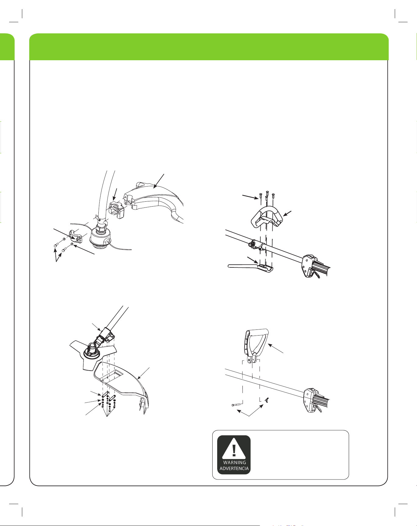
ASSEMBLY
INSTALLING CUTTING ATTACHMENT SHIELD
Use the following instructions if the cutting attachment
shield on your unit is not installed. Use only the
instructions that apply to the type of shaft and shield
that your unit is equipped with.
FOR CURVED SHAFT TRIMMERS
Place the cutting attachment shield and spacer against
tube as shown in (Fig. 1). Use the 2 screws provided
to clamp the cap and shield onto the tube. Tighten the
screws evenly. Make sure the shield does not touch
any rotating parts.
INSTALLING THE D-HANDLE AND LOWER HANDLE
STRAIGHT SHAFT AND ACCESSORY READY
TRIMMERS
1.Locate the 4 screws included in the tool kit.
2.Assemble the upper and lower handle parts and 4
screws as shown in (Fig. 3), positioning the handle
parts evenly over the rubber sleeve on shaft. Do not
completely tighten.
3.While holding the unit in the operating position (Fig.
14), position the D-handle to the location that provides you the best grip.
4.Tighten the clamp screws evenly, until the D-Handle
is secure.
FOR STRAIGHT SHAFT TRIMMERS
Place the cutting attachment shield onto the shaft
mount. Install using provided hardware in the sequence
as shown (Fig.2).
CURVED SHAFT TRIMMERS
1. Installing the D-Handle (non detachable model).
2. Installing D-Handle over the tube in desired position.
3. Install the fasteners as shown (Fig. 4).
4.Tighten until D-Handle is secure.
To prevent serious injury, never operate the
trimmer without the cutting attachment in
place.
LEHR |
6
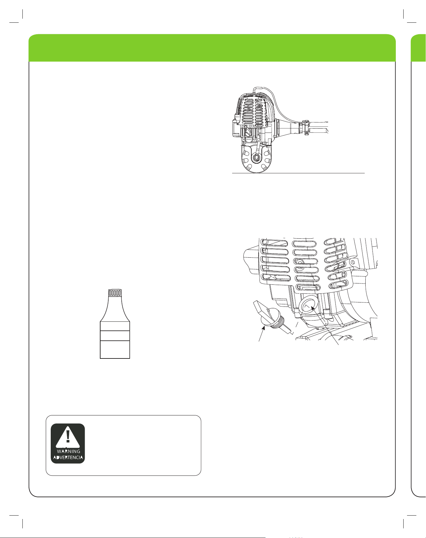
OIL INFORMATION
Fig. 5
4-Cycle Motor Oil
Oil ll plug/dipstick
Oil Fill Hole
Fig. 7
WARNING:
Fig. 6
RECOMMENDED OIL TYPE
Using the proper type and weight of oil in the crankcase
is extremely important. Check the oil before each use
and change the oil regularly. Failure to use the correct oil,
or using dirty oil, can cause premature engine wear and
failure. Use a high-quality SAE 10W-30 weight oil of API
(American Petroleum Institute) service class SF, SG, SH.
ADDING OIL TO THE CRANKCASE
INITIAL USE
NOTE: This unit is shipped without oil. In order to avoid
damage to the unit, put oil in the crankcase before you
attempt to start the unit.
Your unit is supplied with one 1.7 uid oz. (50 mL) bottle
of SAE 10W- 30 SF, SG or SH oil (Fig. 5).
NOTE: Save the bottle of oil. It can be used to measurethe correct amount during future oil changes. See
Changing The Oil (p
.13).
1. Unscrew the top of the bottle of oil and remove the
seal covering the opening. Replace the top. (Fig. 5).
2. Place the unit on a level surface (g.6).
3. Remove the oil plug / dipstick from the crankcase (Fig.7).
4. Pour the entire bottle of oil into the oil ll hole (Fig. 7).
Overfilling crankcase may cause hot oil to drip from
air filter, and smoke to come out from the exhaust.
Check and maintain the proper oil level in the crank
case; it is important and cannot be overemphasized.
Check the oil before each use and change as
needed. See Changing the Oil (p.13).
ALL RIGHTS RESERVED 2008-2009
Check oil before each use and change as needed. Refer
to Changing the Oil (p13).
5. Wipe up any oil that may have spilled and reinstall
the oil plug/dipstick.

LEHR | ALL RIGHTS RESERVED 2008-2009
7
UNDERSTANDING PROPANE
WARNING:
SAFETY WARNINGS FOR PROPANE UNITS
NOTE: Use propane only in containers specically
designed and approved for this unit. Propane is a
combustible gas, it is colorless and thus invisible to the
naked eye. Propane has a harmless odorant added so
that it is possible to smell it. The user should be familiar
with the smell of propane (smells like sulfur or rotten
eggs). If at any time the smell of propane is identied,
turn o the engine. If the leak persists, remove the pro pane canister. Never attempt to operate a unit that has
a suspected leak. Always remove the propane canister
from any unit that has a suspected leak.
CARBON MONOXIDE HAZARD
Burning propane makes Carbon Monoxide (CO). CO is
invisible, has no smell and can kill you. Operating your
trimmer in an enclosed area can be dangerous.
1. Use only in well ventilated areas. If you experience
headache, drowsiness, or nausea, turn unit o and
get fresh air quickly.
2. Never use where people are sleeping.
3. Follow unit instructions for proper use.
HANDLING & STORAGE
1. Keep out of reach of children.
2. Never expose cylinder to heat, sparks, or ame.
Never leave in direct sunlight. Never store at tem -
°
peratures above 120 degrees F
° (49
C).
3. Never store in living spaces.
4. Always use cylinder until it is completely empty.
5. Never rell a disposable cylinder. Relling may cause
an explosion. Federal law forbids transportation if re lled, a penalty up to $500,000, and 5 years impris onment (49 U.S.C. 5124).
6. Never put in luggage or take on trains or aircraft.
7. To discard, contact local refuse hauler or recycle cen
ter. Never put in re or incinerator. Do not puncture. If
your cylinder was purchased with a “Green Key” * or
similar device, install it when empty and cylinder may
be recycled with other steel items.
NOTE: FIRE/EXPLOSION HAZARD
Contains enough gas to cause serious re, explosion,
and burns. To reduce chance of leak, re, or explosion,
take the following precautions:
BEFORE USE
1. Check cylinder and appliance seals. Never use with
damaged or missing seals. Discard cylinder if dirt or
rust particles are in valve area.
2. Turn trimmer o.
3. Attach cylinder outdoors away from pilot lights, ames,
sparks or other ignition sources. These sources can
ignite leaking gas.
4. Hand tighten only. Never use tools to tighten. Overtightening can damage seals.
5. Check for leaks. Put soapy water on connections.
Look for bubbles. Listen for hiss of escaping gas. Feel
for extreme cold. Smell for rotten egg odor. Do not
use if leaking.
6. Read and follow appliance instructions.
DURING USE
Never use near pilot lights, ames, sparks, or other
ignition sources. They can ignite leaking gas.
AFTER USE
1. Turn trimmer o and let cool.
2. Detach cylinder when not in use.
3. Detach outdoors away from pilot lights, ames, sparks,
or other ignition sources, they can ignite leaking gas.
4. Replace cap to keep valve clean.
IN CASE OF FIRE
1. Leave area quickly and call for help.
2. Let cylinder burn out.
* Green Key- is a trademark of the Coleman company
PROPANE IS HIGHLY FLAMMABLE,
AND ITS VAPORS CAN EXPLODE IF
IGNITED.

LEHR |
8
INSTALLING THE PROPANE CANISTER
16.4 OUNCE/
465 GRAM
CANISTER
Fig. 8
WARNING:
WARNING:
WARNING:
WARNING:
USE THE CORRECT PROPANE CANISTER
Always use Propane canisters or “Bottles” that are the
correct size. The 17 ounce or 16.4 ounce/465 g can isters that are approximately 3-7/8 inches (9.5 cm) in
diameter are the correct canisters (Fig. 8). Do not use
the smaller diameter canisters as they will not latch
securely to the unit and vibration may cause damage to
the trimmer and potentially result in a dangerous leak.
Fig. 9B
REMOVING THE PROPANE CANISTER
1. Make sure the engine is o.
2. Un-latch the bottle clamp and push canister against the
guard exposing the propnae connector. Remove the
propane connector by turning it counterclockwise.
Propane
Connector
ATTACHING THE PROPANE CANISTER
1. Make sure the engine is o.
2. If the propane canister to be installed has a protec tive plastic cap over the threaded end, remove it.
Make sure the canister clamp is in the un-latched
position.
3. Insert the threaded end of the propane canister into
the clamp as far as it will go (Fig. 9A). Insert the propane connector onto the threaded end of the canister and screw it
onto threads clockwise (Fig. 9B). Screw it until snug.
Do not over tighten. It may be normal to hear or smell
a slight momentary leak of propane as the connector
is being screwed in. Make sure that the connector is
installed tight enough that any leakage stops. Hand
tight is sufcient. Slide canister back so all of fuel line
components are behind the guard and latch the canister
clamp.
3. Remove the empty canister.
4. Dispose of empty propane canisters in accordance
to Federal, State and local Regulations.
NEVER ATTEMPT TO FORCE A CONNECTOR ONTO A PROPANE CANISTER THAT
HAS IMPROPER OR DAMAGED THREADS.
THIS CONTAINER AND BY-PRODUCTS OF THE
COMBUSTION OF ITS CONTENTS CONTAIN
CHEMICALS KNOWN TO THE STATE OF
CALIFORNIA TO CAUSE CANCER, BIRTH
DEFECTS OR OTHER REPRODUCTIVE HARM.
EXTREMELY FLAMMABLE FIRE/ EXPLOSION HAZARD CONTENTS UNDER
PRESSURE. CARBON MONOXIDE
HAZARD.
Canister
Clamp
Fig. 9A
ALL RIGHTS RESERVED 2008-2009
PROPANE IS EXTREMELY FLAMMABLE.
VAPOR MAY EXPLODE. ALWAYS STOP
THE ENGINE AND ALLOW IT TO COOL
BEFORE REPLACING THE PROPANE
CANISTER. DO NOT SMOKE. KEEPS
SPARKS AND OPEN FLAMES AT A
DISTANCE FROM THE AREA.

LEHR | ALL RIGHTS RESERVED 2008-2009
9
Fig. 11
90° Edging
Hole
INSTALLING ATTACHMENTS
Fig. 10
Receiving Hole
Release Button
Coupler
Upper Shaft
Housing
Knob
Attachment
Housing
Line up parts
Coupler
Fig. 12
Release Button
WARNING:
INSTALLING CUTTING ATTACHMENTS OR ADD-ONS
NOTE: Place the unit on the ground or on a work bench
to make accessory installation or removal easier.
1. Turn knob counterclockwise to loosen (Fig. 10).
2. While rmly holding the attachment, push it straight into
coupler (Fig. 10).
NOTE: Aligning the release button with receiving hole
will help installation (Fig. 10).
NOTE: Always install the attachment so that the engine
is upright (propane tank on bottom) when unit is oper ated. A secondary receiving hole is provided for use of a
trimmer being used for edgi
ng only. No other accessory
should be used in this secondary hole (90° edging hole)
( Fig. 11).
REMOVING CUTTING ATTACHMENTS OR ADD-ONS
1. Turn the knob counterclockwise to loosen (Fig. 12).
2. Press and hold the release button (Fig. 12).
3. While rmly holding the upper shaft housing, pull
the cutting attachment or add-on straight out of the
coupler (Fig. 12).
3. Turn the knob clockwise to tighten (Fig. 11). Unit is
ready to use.
4. For edging (when using the string trimmer head cut ting attachment) lock the release button of the cut ting attachment into the 90° edging hole (Fig. 11), so
that the engine remains in the upright position while
operating.
NOTE: Lock the release button in the receiving hole and
securely tighten the knob before operating this unit.
NOTE: Attachments are to be used in the receiving hole
only. Using the wrong hole could lead to personal injury
or damage to the unit.
TO AVOID SERIOUS INJURY AND
DAMAGE TO THE UNIT, SHUT OFF
THE UNIT BEFORE REMOVING OR
INSTALLING ATTACHMENTS OR
ADD-ONS.

LEHR | ALL RIGHTS RESERVED 2008-2009
10
STARTING/STOPPING
Safety trigger
Stop/O
Start/On(I)
Throttle Control
Fig. 13
WARNING:
WARNING:
STARTING INSTRUCTIONS
1. Check the oil level in the crankcase. Refer to
the Oil Level ( p. 12).
2. Turn switch to ON position (Fig. 13).
NOTE: If your unit is equipped with a spring loaded type
ON/OFF switch, it will always remain in the ON position.
3. Place trimmer rmly on the ground or a very sturdy
work surface. Make sure cutting head is clear of all
objects. Make sure all bystanders are a minimum
of 50 feet (15 m) away. Do not attempt to start near
pilot lights or any open ame. Do not smoke. Grasp
the starter rope handle with one hand and the handle
pole with the other hand ( Fig. 14).
4. With the unit in the starting position, do not squeeze
the throttle control (Fig. 13). Then pull the rope
smoothly and briskly. The engine should start.
Engine should start with 3-5 pulls. Once warm, the
engine should start on the rst pull.
Checking
NOTE: On the rst use, it may take extra pulls to ll the
fuel system with propane.
5. Squeeze the throttle control slightly to warm up the
engine for 15 to 30 seconds. In cold weather, move
the throttle slowly until the engine warms up for 30 to
60 seconds.
NOTE: When starting the engine in very hot or cold
conditions it may be necessary to squeeze the throttle
open while pulling the starter rope.
Fig. 14
STOPPING INSTRUCTIONS
1. Release your hand from the throttle control. Allow the
engine to cool down by idling.
2. If your unit is equipped with a spring loaded ON/
OFF switch, press and hold the button on OFF until
the unit stops. Otherwise, push the switch to the o
position.
3. When done using the trimmer for the day, disconnect
the propane canister from the unit.
AVOID ACCIDENTAL STARTING. MAKE SURE YOU ARE IN
THE STARTING POSITION WHEN PULLING THE STARTER
ROPE. (FIG. 14) TO AVOID SERIOUS INJURY, THE OPERATOR
AND UNIT MUST BE IN A STABLE POSITION WHILE
STARTING. MAKE SURE THAT ANY ADD-ON ITEM IS
INSTALLED CORRECTLY AND SECURE BEFORE STARTING
UN I T.
ALWAYS WEAR EYE, HEARING, FOOT
AND BODY PROTECTION TO REDUCE
THE RISK OF INJURY WHEN OPERATING THIS UNIT.

LEHR | ALL RIGHTS RESERVED 2008-2009
11
OPERATION
Fig. 15
30°
Fig. 16
OPERATING YOUR TRIMMER
Before operating the unit, stand in the operating posi tion (Fig. 15). Check for the following:
• The operator is wearing eye protection and proper
clothing.
• With a slightly-bent right arm, the operator’s right
hand is holding the shaft grip.
• The operator’s left arm is straight, the left hand hold -
ing the handle.
• The unit is at waist level.
• The cutting attachment is parallel to the ground and
easily contacts the grass without the need to bend over.
ADVANCING THE CUTTING LINE
String advance is controlled by tapping the string head
on grass while running engine at full throttle.
1. Run engine at full throttle.
2. Tap the knob on ground to advance string. The string
advances each time the knob is tapped. Do not hold
the knob on the ground.
For example, the line will wear faster when trimming
against a foundation wall as opposed to trimming
around a tree.
Some line breakage will occur from:
• Entanglement with foreign matter
• Normal line fatigue
• Attempting to cut thick, stalky weeds
• Forcing the line into objects such as walls or fence posts
HOLDING THE TRIMMER
TIPS FOR BEST TRIMMING RESULTS
• For best trimming results, operate unit at full throttle.
• Keep the cutting attachment parallel to the ground.
• Do not force the cutting attachment. Allow the tip
of the line to do the cutting, especially along walls.
Cutting with more than the tip will reduce cutting ef -
ficiency and may overload the engine.
• Cut grass over 8 inches (200 mm) by working from
top to bottom in small increments to avoid prema -
ture line wear or engine drag.
• Slowly move the trimmer into and out of the cutting
area at the desired height. Move either in a forward-
backward or side-to-side motion. Cutting shorter
lengths produces the best results.
• Trim only when grass and weeds are dry.
• The life of your cutting line is dependent upon:
1. Proper adherence to explained trimming techniques
2. What vegetation is cut
DECORATIVE TRIMMING
Decorative trimming is accomplished by removing
all vegetation around trees, posts, fences and more.
Rotate the whole unit so that the cutting attachment is
at a 30-degree angle to the ground (Fig. 16).
3. Where vegetation is cut

LEHR | ALL RIGHTS RESERVED 2008-2009
12
WARNING:
MAINTENANCE
Oil Fill Hole
Oil Fill Plug/
Dipstick
Fig. 18
Oil Fill Plug/Dipstick
O-ring
Full
Add
Fig. 17
WARNING:
FREQUENCY MAINTENANCE REQUIRED REFER TO
BEFORE STARTING ENGINE CHECK
EVERY 10 HOURS CLEAN AND RE-OIL AIR FILTER PAGE 13
AT
FIRST
CHANGE
10
HOURS CHANGE OIL PAGE 13
EVERY 25 HOURS THEREAFTER CHANGE OIL PAGE 13
25
HOURS
HOURS
CHECK
R OCKER ARM CLEARANCE
EVERY 25
EVERY
OIL
SPARK PLUG POSITION
ADJ USTMENT
AND GAP
PAGE 6
PAGE 14
PAGE 17
Perform these required maintenance procedures at the
frequency stated in the table. These procedures should
also be a part of any seasonal tune-up.
NOTE: Failure to maintain your trimmer at the recom mended schedule may result in poor performance and/
or cause permanent damage to your trimmer
NOTE: Some maintenance procedures may require
special tools or skills. If you are unsure about these pro cedures call 1-866-941-LEHR for the location of your
nearest authorized service dealer.
NOTE: Maintenance, replacement, or repair of the
emission control devices and system may be performed
by any non-road engine repair establishment, individual
or authorized service dealer.
CHECKING THE OIL LEVEL
The importance of checking and maintaining the proper
oil level in the crankcase cannot be overemphasized.
Check oil before each use:
1. Stop the engine and allow to cool.
2. Place the unit on a at, level surface to get a proper
oil level reading.
3. Keep dirt, grass clippings and other debris out of the
engine. Clean the area around the oil ll plug/dipstick
before removing it.
4. Remove the oil ll plug/dipstick and wipe o oil. Rein sert it all the way back in.
5. Remove the oil ll plug/dipstick and check the oil level.
Oil should be between the add and ll marks. (Fig. 17)
6. If the level is low, add a small amount of oil to the oil
ll hole (Fig. 18) and recheck. Repeat this procedure
until the oil level reaches the full mark of the dipstick:
NOTE: Do not overll the unit.
NOTE: Make sure the O-Ring is in place on the oil ll
plug/dipstick when checking and changing the oil
(Fig. 17).
WHEN SERVICING, USE ONLY
IDENTICAL REPLACEMENT PARTS. USE
OF ANY OTHER PARTS MAY CREATE A
HAZARD OR CAUSE PRODUCT
DAMAGE
TO PREVENT EXTENSIVE ENGINE WEAR AND
DAMGE TO THE UNIT, ALWAYS MAINTAIN THE
PROPER OIL LEVEL IN THE CRANKCASE. NEVER
OPERATE THE UNIT WITH THE LEVEL BELOW
THE BOTTOM OF THE DIPSTICK.

LEHR | ALL RIGHTS RESERVED 2008-2009
13
Fig. 20
4-Cycle Motor Oil
WARNING:
MAINTENANCE
Fig. 19
CHANGING THE OIL
For a new engine, change the oil after the rst 10 hours
of operation. Change the oil while the engine is still
warm but not hot. The oil will ow freely and carry away
more impurities.
1. Unplug spark plug boot to prevent accidental starting.
2. Remove the oil ll plug/dipstick.
3. Pour the oil out of the oil ll hole and into a container
by tipping the unit to its side (Fig. 19). Allow ample
time for complete drainage.
CLEANING THE AIR FILTER
Clean and re-oil the air lter every 10 hours of operation.
It is an important item to maintain. Failure to maintain
your air lter properly can result in poor performance or
can cause permanent damage to your engine.
1. Remove phillips head screw in air lter cover. Then
pull the air lter cover out and upwards (Fig. 21) .
2. Remove the air lter (Fig. 21).
Air Filter
Air Filter
Cover
Screw
Air Filter
Base Plate
NOTE: Wear gloves to prevent injury when handling the
unit.
4. Wipe up any oil residue on the unit and clean up any
oil that may have spilled. Dispose of the oil according
to Federal, State and local regulations.
5. Rell the crankcase with 1.7 uid oz. (50 mL) of SAE
10W-30 SF, SG, or SH oil.
NOTE:
The bottle measure approximately 1.7 fluid oz/50 ml.
Check the level with the dipstick. If the level is low,
add a small amount of oil and recheck.
Do not over fill (Fig. 17).
6. Replace the oil ll plug/dipstick.
7. Reconnect the spark plug boot.
Fig. 21
3. Wash the lter in detergent and water. Rinse the lter
thoroughly and allow it to dry.
4. Apply enough clean SAE 10W-30 motor oil to lightly
coat the lter.
5. Squeeze the lter and remove excess oil.
6. Replace the lter.
NOTE: If the unit is operated without the air lter, you
will VOID the warranty.
7. Reinstall the air lter cover. Position the hooks on the
top of the air lter base plate into the slots at the top
of the lter cover.
8. Swing the cover until the air lter cover snaps into
place and replace the screw.
TO AVOID SERIOUS PERSONAL INJURY,
BE SURE TO TURN THE UNIT OFF
BEFORE SERVICING IT.

LEHR | ALL RIGHTS RESERVED 2008-2009
14
Idle Adjustment
Screw
Fig.22
WARNING:
0.02 in.
(0.5 mm)
Fig.23
MAINTENANCE
CARURETOR ADJUSTMENT
The idle speed of the engine is adjustable. An idle adjust ment screw is on the rear side of the carburetor (Fig. 22).
NOTE: Careless adjustments can seriously damage
your unit. An authorized service dealer should make
carburetor adjustments.
CLEAN AIR FILTER
The condition of the air lter is important to the op eration of the unit. A dirty or oil saturated air lter will
restrict air ow. This is often mistaken for an out of ad justment carburetor. Check the condition of the air lter
before adjusting the idle speed screw. Refer to Cleaning
Air Filter (p. 13).
ADJUST IDLE SPEED SCREW
If, after checking the fuel and cleaning the air lter, the
engine still will not idle, adjust the idle speed screw as
follows:
1.Start the engine and let it run at a high idle for a min ute to warm up. Refer to Starting/Stopping (p. 10)
instructions.
2. Release the throttle trigger and let the engine idle. If
the engine stops, use a small phillips or at blade to
turn the idle speed screw in, clockwise, 1/8 of a turn
at a time (as needed) until the engine idles smoothly.
NOTE: The cutting attachment should not rotate when
the engine idles.
3. If the cutting attachment rotates when the engine
idles, turn the idle speed screw counterclockwise
1/8 of a turn at a time (as needed), to reduce idle
speed. Checking the fuel, cleaning the air lter, and
adjusting the idle speed should solve most engine
problems. If not and all of the following are true:
• the engine will not idle
• the engine hesitates or stalls on acceleration
•there is a loss of engine power
Check the spark plug for proper gap and condition. If
problem still occurs, have the carburetor adjusted by an
authorized service dealer.
REPLACING THE SPARK PLUGS
Use a replacement part number NGK CMR6A. The cor rect air gap is 0.02 in. (0.5 mm). Remove the plug after
every 25 hours of operation and check its condition.
1.Stop the engine and allow it to cool. Remove the
spark plug cover. Grasp the plug wire rmly and pull
the cap from the spark plug.
2.Clean dirt from around the spark plug. Remove the
spark plug from the cylinder head by turning a 5/8 in.
socket counterclockwise.
3.Replace cracked, fouled or dirty spark plug. Set the air
gap at 0.02 in. (0.5 mm.) using a feeler gauge (Fig 23).
4.Install a correctly-gapped spark plug in the cylinder
head. Turn the 5/8 in. socket clockwise until snug.
If using a torque wrench torque to: 110-120 in. lb.
(12.3-13.5 N-m)
NOTE: Do not over tighten.
DO NOT SAND BLAST, SCRAPE, OR
CLEAN SPARK PLUG ELECTRODES.
GRIT IN THE ENGINE COULD DAMAGE
THE CYLINDER.

LEHR | ALL RIGHT RESERVED 2008-2009
15
Fig.24
Bump Feed
Button
Hole
Fig.25
Fig. 26
Wire Reel
Retention
Hook
Retention
Hook
Wrap Bottom CCW
Hook
Wrap Top CCW
Hook
Fig. 27
Trimmer Head
Body
Spring
Reel
Bump Feed
Button
Nut
Fig.28
Fig.29
Fig.30
MAINTENANCE
TRIMMER HEAD LINE INSTALLATION
SMALL BUMP FEED HEAD (.080” Line)
1. Review gure 28 for names of parts referred to in these
instructions.
2. Lock shaft by inserting allen key into hole in collar and turn
until it engages groove inside. When shaft can no longer
rotate, loosen head by turning it as shown (Fig. 24).
3. Loosen bump feed button and remove by turning CCW
(Fig. 25).
8. Continue winding cord in direction indicated as
shown, leave about 6 inches free length (15-20 cm)
to pull wire through holes in body. Snap the lines
through top notches in reel (Fig. 26 and Fig. 27).
9. Feed the free ends of
lines through holes in
body while inserting
reel back into body.
Hold reel in place
against spring pres sure (Fig. 28).
4. Pull reel out of trimmer body, take care to not lose
the spring behind it.
5. Un-wind and remove the remnants of the line left on
the reel. Note how the ends of the line are hooked in
place and the direction it is wound.
6. If using new line from a bulk spool, cut 2 pieces of
line 7.5 ft (2.28 m) long. Insert each line into one of
the holes on each retention hook opposite of the
direction of the rotation about1/2 inch deep.
7. Wrap line 180° and wind extra line in the opposite
direction of rotation of the head as shown (Fig. 26).
NOTE: Always use original equipment manufacturer replacement line. Lines other than those
specied may make the engine overheat or fail.
10. While holding reel into body, screw bump feed but ton and nut onto threads by turning CW (Fig. 29).
11. Insert allen key into hole tighten by turning body as
shown (Fig. 30).

LEHR | ALL RIGHTS RESERVED 2008-2009
16
Fig.34
Snap to groove to
pull through cover
Fig.31
T
op view
Trimmer Head Bod
y
Fig.32
Tab
Fig.33
Retention
Hook
Fig 35
Trimmer Head
Body
Spring
Reel
Bump Feed
Button
Trimmer Head Body
Bottom
Holes
Tab “click”
Fig.36
T
op view
Fig.3 7
MAINTENANCE
TRIMMER HEAD LINE INSTALLATION
LARGE BUMP FEED HEAD (.095” Line)
1. Lock shaft by inserting allen key into groove. Loosen
by turning head as shown for straight shaft. If your
model is a curved shaft, loosen by turning opposite
the direction shown in (Fig. 31).
2. Depress tab and twist trimmer head body CW to
disassemble (Fig. 32).
6. Snap the free length of lines into top grooves in reel and pull
through holes on trimmer head body (Fig. 34 and Fig. 35).
7. Close assembly in sequence as shown in (Fig. 35).
8. Reassemble by lining up the 4 tabs on trimmer head
body and bottom. Turn CCW until “click” (Fig. 36).
3. If using new line from a bulk spool, cut 2 pieces of
line 7.5’ (2.28 m) long. Insert each line into one of the
holes on each retention hook opposite of the direc tion of the rotation about 1/2 in (12-7 mm) deep.
4. Wrap line 180° and wind extra line in the opposite
direction of rotation of the head (Fig. 33).
5. Wind cord in direction indicated (CW) leaving 6 in (15-20 cm)
access to pull through holes trimmer head body (Fig. 34).
9. Insert allen key into hole, tighten head by turning
as shown for curved shaft and opposite for straight
shaft (Fig. 37).

LEHR | ALL RIghTS ReSeRved 2008-2009
17
Fig. 38
Left-Hand Thread Nut
Cotter Pin
Loosen
Fig.39
Hole
Brush Cutter Blade
Fig.40
Left-Hand Thread Nut
Clamp Plate
Star Washer
Fig. 41
Bottom Shield
Attachment
Screw
Cutting Attachment
Sheild
Fig.42
Engine cover
screws
Engine cover
screws
MAINTENANCE
BrUSH CUTTer BlaDe remoVal / inSTallaTion
1.Remove the cotter pin (Fig. 38).
2. Insert an allen key into the hole in the shroud to
lock the shaft. Remove the left-hand thread nut to
dissasemble with tool provided in the tool kit (Fig. 39).
GUarD CHanGe
NOTE: When using the brush cutter blade remove
the bottom shield attachment by removing the screw.
Replace when using line trimmer head (Fig. 41).
roCKer arm ClearanCe aDJUSTmenT
This requires partial disassembly of the engine. If you
feel unsure or unqualified to perform this, take the unit
to an authorized service center.
1. Remove the four screws on the engine cover with a
phillips head screw driver (Fig. 42).
3. Remove in the sequence shown (Fig. 40).
• For reassembly, install all components in the correct
• Tighten the left-hand thread nut until snug and install
sequence ( Fig. 40).
a new cotter pin.
2. Remove the engine cover.
3. Disconnect the spark plug wire.
4. Clean dirt from around the spark plug. Remove the
spark plug by using tool provided, turn CCW.
NOTE: Inspect the valve to rocker arm clearance with
`
a feeler gage after the first 25 hours of operation. The
engine must be cold when checking or adjusting the
valve clearances. This task should be performed in a
clean dust free environment.

LEHR | ALL RIGHTS RESERVED 2008-2009
18
Fig.43
Rocker Arm
Cover
Rocker Arm Cover
Screws
Jam Nuts
Adjusting Screws
Rocker Arm
Feeler Gauge
Exhaust Valve
Intake Valve
Fig.44
WARNING:
MAINTENANCE
ROCKER ARM CLEARANCE ADJUSTMENT
5. Clean dirt from around the rocker arm cover.
6. Remove the three screws holding the rocker arm
cover with a phillips head screwdriver.
7. Remove the rocker arm cover and gasket (Fig. 43).
8. Pull the starter rope slowly to bring the piston to
the top of its travel, (This position is known as top
dead center).Check that the piston is at the top of
its travel by looking down into the spark plug hole.
Both valves should be closed and the rocker arms
should move freely. If this statement is not true,
repeat this step.
9. Slide a feeler gage between the rocker arm and the
valve return spring. Measure the distance between
the rocker arm and valve stem (Fig. 44) Take care
to only measure the free play. It is very easy to
insert too thick a feeler gauge and accidentally
depress the valve and spring. Measure both the
intake and exhaust valve distances.
IF THE CLEARANCE IS NOT WITHIN SPECIFICATION
1. Loosen the jam nut and turn the adjusting screw
as necessary. To increase the clearance, turn the
adjusting screw CCW. To decrease the clearance,
turn the adjusting screw CW.
2. Tighten the jam nut when the clearance is set.
3. Recheck the both clearances. Readjust if necessary.
4. Reinstall the rocker arm cover using a new gasket.
5. Tighten cover screws evenly until snug.
6. Reinstall the engine cover checking the alignment of
the cover. Tighten the four engine cover screws until
snug.
• The recommended clearance for both intake and
exhaust is 0.076-0.152mm (0.003-0.006in).
• Use a standard automotive 0.127mm (0.005in) feeler gage.
TO PREVENT SERIOUS INJURY, NEVER PERFORM
MAINTENANCE OR REPAIRS WITH UNIT RUNNING.
ALWAYS SERVICE AND REPAIR A COOL UNIT. DISCONNECT THE SPARK PLUG WIRE TO ENSURE THAT THE
UNIT CANNOT START.
10. Check the spark plug and reinstall (See
the Spark Plug (p.14)
.
11. Reinstall the spark plug wire.
Replacing

LEHR | ALL RIGHTS RESERVED 2008-2009
19
CLEANING AND STORAGE
WARNING:
CLEANING
Use a small brush to clean the outside of the unit. Do
not use strong detergents. Household cleaners that
contain aromatic oils such as pine and lemon, and sol vents such as kerosene, can damage plastic housing or
handle. Wipe o any moisture with soft cloth.
STORAGE
• Remove propane canister.
• Never store the unit with attached propane canister where
fumes may reach an open ame or spark.
• Allow the engine to cool before storing.
• Lock up the unit to prevent unauthorized use or damage.
• Store the unit in a dry, well-ventilated area.
• Store unit out of reach of children.
TO AVOID SERIOUS INJURY, ALWAYS
TURN YOUR UNIT OFF AND ALLOW
IT TO COOL BEFORE YOU SERVICE
I T.
LONG TERM STORAGE
1. Remove propane canister.
2. Allow the engine to cool. Remove the spark plug and
put 5 drops of high quality motor oil into the cylinder.
Pull the starter rope slowly to distribute the oil. Rein stall the spark plug.
NOTE: Remove the spark plug and drain all of the oil
from the cylinder before attempting to start the trimmer
after storage.
3. Change the oil, referring to Changing the Oil (p.13) .
Dispose of the old oil in accordance to Federal, State
and Local regulations.
4. Thoroughly clean the unit and inspect for any loose
or damaged parts. Repair or replace damaged parts
and tighten loose screws, nuts or bolts. The unit is
ready for storage.
TRANSPORTING
• Allow the engine to cool before transporting.
• Secure the unit while transporting.
• Remove propane canister.
TROUBLE SHOOTING
ENGINE WILL NOT START
CAUSE
EMPTY PROPANE CANISTER INSTALL FULL CANISTER
BAD SPARK PLUG REPLACE THE SPARK PLUG
ENGINE WILL NOT IDLE
CAUSE
AIR FILTER IS PLUGGED REPLACE THE AIR FILTER
IMPROPER CARBURETOR ADJUSTMENT
ENGINE WILL NOT ACCELERATE
CAUSE ACTION
CUTTING ATTACHMENT BOUND WITH GRASS
DIRTY AIR FILTER CLEAN OR REPLACE THE AIR FILTER
ENGINE LACKS POWER OR STALLS WHEN CUTTING
CAUSE ACTION
BAD SPARK PLUG
ACTION
ACTION
ADJUST ACCORDING TO THE ‘C ARBURETOR
ADJUSTMENTS’ SECTION OR TAKE TO AN
AUTHORIZED SERVICE DEALER FOR AN ADJUSTMENT
STOP ENGINE AND CLEAN THE CUTTING ATTACHMENT
IF FURTHER ASSISTANCE IS REQUIRED, CONTACT A QUALIFIED SERVICE DEALERF .

LEHR | ALL RIGHTS RESERVES 2008-2009
20
SPECIFICATIONS
ENGINE*
ENGINE TYPE
DISPLACEMENT
CLUTCH TYPE
OPERATING R.P.M.
IDLE SPEED
IGNITION TYPE
IGNITION SWITCH
VALVE CLEARANCE
SPARK PLUG GAP
LUBRICATION
CRANKCASE OIL CAPACITY
FUEL
AIR COOLED 4-CYCLE
25.4 CC
CENTRIFUGAL
6,800-9300 R.P.M.
3,000-3,400 R.P.M.
ELECTRONIC
PUSH ON/OFF SWITCH
0.076-0.152MM (0.003-0.006 IN)
0.020 INCH (0.5 MM)
SAE 10W-30 OIL
1.7 FLUID OZ. (50mL)
PROPANE 16.4
OZ CANISTER
CARBURETOR
STARTER
MUFFLER
THROTTLE
DRIVE SHAFT AND HOUSING
DRIVE SHAFT HOUSING
THROTTLE CONTROL
APPROXIMATE UNIT WEIGHT
CUTTING MECHANISM
LINE SPOOL DIAMETER
TRIMMING LINE DIAMETER
CUTTING PATH DIAMETER
CHOKE-LESS, ALL-POSITION
AUTO REWIND
BAFFLED WITH
SAFETY LOCK WITH MANUAL SPRING RETURN
ALUMINUM
BUMP
FINGER
FEED
0.080 /0.095 INCHES
17 INCHES (431.8 MM)
-TIP TRIGGER
13.1-14.9 LBS
CUTTING HEAD
2.4/3.4 INCHES
GUARD
TUBE
ALL SPECIFICATIONS ARE BASED ON THE LASTEST PRODUCT INFORMATION AT THE TIME OF PRINTING.
WE RESERVE THE RIGHT TO MAKE CHANGES AT ANY TIME WITHOUT NOTICE.

LEHR | ALL RIGHTS RESERVED 2008-2009
21
MANUFACTURER’S LIMITED WARRANTY
The limited warranty set forth below is given by LEH R with respect to new merchandise purchased and used in the United States and Canada, its possessions and
territories.
LEHR warrants to the original purchaser that each new LEH R brand power tool or
attachment is free from defects in material and workmanship and agrees to repair or
replace under this warranty any defective power product or attachment as follows
from the original date of purchase.
3 YEARS -- Parts and Labor, on carburetor.
2 YEARS -- Parts and Labor, when used for household purposes.
90 DAYS -- Parts and Labor, when used for commercial, professional, or income
producing purposes.
30 DAYS -- Parts and Labor, if used for rental purposes.
This warranty is not transferable and does not cover damage or liability caused by
improper handling, improper maintenance, or the use of accessories and/or attachments not specically recommended by LEHR for this product. In addition, it does not
cover any product that has been subject to misuse, neglect, negligence, or accident,
or has been operated in any way contrary to the operating instructions specied in
this operator’s manual. Additionally, this warranty does not cover tune-ups, spark
plugs, carburetor adjustments, lters, cutting line, bump knobs, outer spools, inner
reels, starter pulley, or rotating head parts that will wear and require replacement with
reasonable use during the warranty period. This warranty does not cover pre delivery
setup or normal adjustments explained in the instruction manual.
THIS WARRA NTY GIVES YOU SP E CIFIC L EG AL RIGHTS, A ND YOU MAY HAVE
OTHE R RI GHTS W HICH VARY FROM STAT E TO STAT E .
NO CLAIMS FOR CO NSEQU ENTIAL OR OT HER DAMAGE S WILL B E ALLOW ED,
AND THE RE ARE NO OT HER EXPR ESS WARRA NTIES EXCEPT T HOS E E XPRE SSLY
STIPULAT ED HE REIN. SOM E STAT ES DO NOT ALLOW LIMITATIO NS O N HOW
LONG AN IMPLIED WARRA NTY LASTS OR T HE EXCLUSIO N OR LIMITATIO NS OF
INCIDENTAL OR CO NS EQU ENTIAL DAMAGE S, SO T HE ABO VE LIMITATIONS OR
EXCLUSIO N MAY NOT APPLY TO YOU.
LEHR does not extend any warranty for products sold or exported outside of the
United States or Canada, its possessions and territories, except those sold through
LEHR’s authorized channels of export distribution. The policy of LEH R is to continuously improve its products. Therefore, LEH R reserves the right to change, modify, or
discontinue models, designs, specications, and accessories of all products at any
time without notice or obligation to any purchaser.
HOW TO OBTAI N S ER VICE: Warranty service is available, with proof of purchase
through your local authorized service dealer. To locate the dealer in your area, visit our
website at www.golehr.com or call 1-866-941-LEHR or write to
8922 Ellis Ave. LA, CA 90034.
YOUR WARRANTY RIGHTS AND OBLIGATIONS
The California Air Resources Board, the Environmental Protection Agency and LEH R,
Inc. are pleased to explain the emissions control system’s warranty on your 2009 and
later small o-road engine. In California and the 49 states, new equipment that use
small o-road engines must be designed, built, and equipped to meet the State’s
stringent anti-smog standards. LEH R, Inc. must warrant the emissions control system
on your small o-road engine for the period listed below provided there has been no
abuse, neglect or improper maintenance of your equipment. Your emissions control
system may include parts such as: carburetors or fuel injection system, ignition
system, catalytic converters, fuel tanks, valves, lters, clamps, connectors, and other
associated components. Also, included may be hoses, belts, connectors, sensors,
and other emission-related assemblies. Where a warrantable condition exists, L EHR
will repair your small o-road engine at no cost to you including diagnosis, parts and
labor at an authorized service dealer.
MANUFACTURER’S WARRANTY COVERAGE:
This emissions control system is warranted for two years. If any emissions-related
part on your equipment is defective, the part will be repaired or replaced by LEH R.
OWNER’S WARRANTY RESPONSIBILITIES:
As the small o-road engine owner, you are responsible for performance of the required maintenance listed in your owner’s manual. LEHR recommends that you retain
all receipts covering maintenance on your small o-road engine, but LEH R cannot
deny warranty solely for the lack of receipts or your failure to
ensure the performance of all scheduled maintenance. As the small o-road engine
owner, you should however be aware that LEHR may deny you warranty coverage
if your small o-road engine or a part has failed due to abuse, neglect, or improper
maintenance or unapproved modications.
You are responsible for presenting your small o-road engine to a LEHR service
center as soon as the problem exists. The warranty repairs should be completed in a
reasonable amount of time, not to exceed 30 days. If you have a question regarding
your warranty coverage, you should contact LEHR at 1-866-941-L EHR.
DEFECTS WARRANTY REQUIREMENTS:
(a) The warranty period begins on the date the engine or equipment is delivered to an
ultimate purchaser.
(b) General Emissions
engine or equipment must warrant to the ultimate purchaser and each subsequent
owner that the engine or equipment is:
Designed, built, and equipped so as to conform with all applicable regulations
adopted by the Air Resources Board; and free from defects in materials and work manship that causes the failure of a warranted part for a period of two years.
(c) The warranty on emissions-related parts will be interpreted as follows:
Any warranted part that is not scheduled for replacement as required maintenance in
the written instructions required by Subsection
(d) Must be warranted for the warranty period dened in Subsection (b)(2). If any such
part fails during the period of warranty coverage, it must be repaired or replaced
by the manufacturer according to Subsection (4) below. Any such part repaired or
replaced under the warranty must be warranted for the remaining warranty period.
Any warranted part that is scheduled only for regular inspection in the written instruc-
tions required by Subsection (d) must be warranted for the warranty period dened
in Subsection (b)(2). A statement in such written instructions to the eect of “repair
or replace as necessary” will not reduce the period of warranty coverage. Any
such part repaired or replaced under warranty must be warranted for the remaining
warranty period.
Any warranted part that is scheduled for replacement as required maintenance in the
written instructions required by Subsection (d) must be warranted for the period of
time prior to the rst scheduled replacement point for that part. If the part fails prior
to the rst scheduled replacement, the part must be repaired or replaced by the
engine manufacturer according to Subsection (4) below.
Section 4: Any such part repaired or replaced under warranty must be warranted for
the remainder of the period prior to the rst scheduled replacement point for the
part. Repair or replacement of any warranted part under the warranty must be
performed at no charge to the owner at a warranty station.
Notwithstanding the provisions of Subsection (4) above, warranty services or repairs
must be provided at all manufacturer distribution centers that are franchised to
service the subject engines.
The owner must not be charged for diagnostic labor that leads to the determination
that a warranted part is in fact defective, provided that such diagnostic work is
performed at a warranty station.
The manufacturer is liable for damages to other engine components proximately
caused by a failure under warranty of any warranted part.
Throughout the emissions warranty period dened in Subsection (b)(2), the manu-
facturer must maintain a supply of warranted parts sufcient to meet the expected
demand for such parts.
Any replacement part may be used in the performance of any warranty maintenance
or repairs and must be provided without charge to the owner. Such use will not
reduce the warranty obligations of the manufacturer.
Add-on or modied parts that are not exempted by the Air Resources Board may not
be used. The use of any non-exempted add-on or modied parts will be grounds
for disallowing a warranty claim. The manufacturer will not be liable to warrant
failures of warranted parts caused by the use of a non-exempted add-on or modi ed part.
The manufacturer issuing the warranty shall provide any documents that describe that
manufacturer’s warranty procedures or policies within ve working days of request
by the Air Resources Board.
(d) Emission Warranty Parts List.
The following components are included in the emission related warranty of the engine:
Air Filter, Carburetor, Regulator, Fuel Lines & Fittings, Fuel Valve, Ignition Coil, Spark
Plug, Valves, CAM and Mufer.
LEHR will furnish with each new engine written instructions for the maintenance and
use of the engine by the owner.
Warranty Coverage. The manufacturer of each small o-road

NOTES
22
LEHR | ALL RIGHT RESERVED 2008-2009
 Loading...