

Page 1

OPERATOR’S MANUAL
PROPANE POWERED
OUTBOARD MARINE ENGINE
5 HP
MODEL:
LP 5.0S
LP 5.0L
CAUTION: BEFORE OPERATING THIS PRODUCT,
READ AND FOLLOW ALL SAFETY RULES AND
OPERATING INSTRUCTIONS.
TABLE OF CONTENTS
Important Manual Information....................................................1
General Information.........................................................................2
Installation............................................................................................7
Operation..............................................................................................8
Maintenance......................................................................................13
Troubleshooting...............................................................................21
Specications.....................................................................................24
Warranty..............................................................................................25
FOR SERVICE
Call 1-866-941-LEHR (5347)
WARNING:
THIS PRODUCT CONTAINS CHEMICALS
KNOWN TO THE STATE OF CALIFORNIA
TO CAUSE CANCER, BIRTH DEFECTS OR
OTHER REPRODUCTIVE HARM.
LEHR | ALL RIGHTS RESERVED 2010-2011
LEHR | ALL RIGHTS RESERVED 2012-2013
Page 2

UNDERSTANDING PROPANE
SAFETY WARNINGS FOR PROPANE UNITS
NOTE: Use propane only in containers and/or remote
larger tanks specically designed and approved for this
unit. Propane is a combustible gas, it is colorless and
thus invisible to the naked eye. Propane has a harmless
odorant added so that it is possible to smell it. The user
should be familiar with the smell of propane (smells like
sulfur or rotten eggs). If at any time the smell of propane
is identied, turn o the engine. If the leak persists,
remove the pro-pane canister. Never attempt to operate
a unit that has a suspected leak. Always remove the
propane canister from any unit that has a suspected leak.
CARBON MONOXIDE HAZARD
Burning propane makes Carbon Monoxide (CO). CO is
invisible, has no smell and can kill you. Operating your
outboard engine in an enclosed area can be dangerous.
1. Use only in well ventilated areas. If you experience
headache, drowsiness, or nausea, turn unit o and
get fresh air quickly.
2. Never use where people are sleeping.
3. Follow unit instructions for proper use.
HANDLING & STORAGE
1. Keep out of reach of children.
2. Never expose cylinder to heat, sparks, or ame.
Never store in direct sunlight.
Never store at temperatures above 120 degrees F
°
(49° C).
3. Never store in living spaces.
4. Always use cylinder until it is completely empty.
5. Never rell a disposable cylinder. Relling may cause
an explosion. Federal law forbids transportation if
relled, a penalty up to $500,000, and 5 years
imprisonment (49 U.S.C. 5124).
6. Never store in luggage or take on trains or aircraft.
7. To discard, contact local refuse hauler or recycle center.
Never put in re or incinerator. Do not puncture.
If your cylinder was purchased with a “Green Key” * or
similar device, install it when empty and cylinder may
be recycled with other steel items.
NOTE: FIRE/EXPLOSION HAZARD
Contains enough gas to cause serious re, explosion,
and burns. To reduce chance of leak, re, or explosion,
take the following precautions:
BEFORE USE
1. Check cylinder and appliance seals. Never use with
damaged or missing seals. Discard cylinder if dirt or
rust particles are in valve area.
2. Turn engine o.
3. Attach cylinder outdoors away from pilot lights, ames,
sparks or other ignition sources. These sources can
ignite leaking gas.
4. Hand tighten only. Never use tools to tighten.
Over tightening can damage seals.
5. Check for leaks. Put soapy water on connections.
Look for bubbles. Listen for hiss of escaping gas. Feel
for extreme cold. Smell for rotten egg odor. Do not
use if leaking.
6. Read and follow operation instructions.
DURING USE
Never use near pilot lights, ames, sparks, or other
ignition sources. They can ignite leaking gas.
AFTER USE
1. Turn engine o and let cool.
2. Detach cylinder when not in use.
3. Detach outdoors away from pilot lights, ames, sparks,
or other ignition sources, they can ignite leaking gas.
4. Replace cap to keep valve clean.
IN CASE OF FIRE
1. Leave area quickly and call for help.
2. Let the cylinder burn out.
WARNING:
PROPANE IS HIGHLY FLAMMABLE, AND ITS
VAPORS CAN EXPLODE IF IGNITED.
* Green Key- is a trademark of the Coleman company
Page 3
IMPORTANT MANUAL INFORMATION
TO THE OWNER
Thank you for purchasing a LEHR propane outboard engine. This operator’s manual explains information
needed for proper operation, maintenance, and care of your LEHR outboard motor. Understanding and
following these instructions will help you get the most trouble free use from your LEHR outboard. If you
have any questions about operation or maintenance of your outboard motor please contact LEHR at
1-866-941-LEHR (5347).
READ THE OPERATOR’S MANUAL BEFORE OPERATING YOUR LEHR OUTBOARD MOTOR
Read this manual. Read all manuals supplied with the boat. Read all labels on the outboard motor and the
boat. If you need any additional information, contact your LEHR dealer or call 1-866-941-LEHR (5347).
WARNING
Warning symbol indicates: ATTENTION! YOUR SAFETY IS INVOLVED! Failure to follow WARNING
instructions could result in severe injury or death to the machine operator, a bystander, or a person
inspecting or repairing the outboard motor.
NOTE
A “NOTE” provides information to make procedures easier or clearer. To ensure long product life, LEHR
recommends that you use the product and perform the specified periodic inspections and maintenance by
correctly following the instructions in the operator’s manual. Note that if you do not follow these instructions,
not only may the product malfunction, but the warranty will also be voided.
This product is covered under one or more of the following U.S. Patents:
7424886 B1, 7631636 B2, 7730868 B2, 7690347 B2, 7739996 B2, 7874275 B1, 7854219 B2, 7735464 B2.
Other Patents Pending.
LEHR |
ALL RIGHTS RESERVED 2012-2013
1
Page 4

GENERAL INFORMATION
• Before mounting or operating the outboard motor, completely read manual and labels. Reading them will
give you a good understanding of the motor and its operation.
• Before operating the boat, read any owner's or operator's manuals supplied with it and all labels. Be sure
you understand all items from the boat manual as well as this engine manual before operating.
• Do not over power the boat with this outboard motor. Overpowering the boat could result in damage to
the boat and injury to all occupants. The rated power of the outboard should be equal to or less than the
rated horsepower capacity of the boat. If the rated horsepower capacity of the boat is unknown, consult
the dealer or boat manufacturer.
• Do not attempt to modify the outboard. Modifications could make the motor unsafe to use and will void the
warranty. Incorrect propeller selection and incorrect use may not only cause engine damage, but also
adversely affect fuel consumption. Consult your dealer for correct use.
• Never operate after drinking alcohol or taking drugs. About 50% of all boating fatalities involve intoxication.
• Have an approved personal flotation device (PFD) on board for every occupant. It is a good idea to wear a
PFD whenever boating. Children and non-swimmers should always wear PFD's, and every one should wear
PFD's when there are potentially hazardous boating conditions.
• Propane is highly flammable, and its vapors are flammable and explosive. Handle and store propane
carefully. Make sure there are no fumes or leaking fuel before starting the engine.
• This product emits exhaust gases which contain carbon monoxide, a colorless, odorless gas which may
cause brain damage or death when inhaled. Symptoms include nausea, dizziness, and drowsiness. Keep
cockpit and cabin areas well ventilated. Avoid blocking exhaust outlets.
• Check throttle, shift, and steering for proper operation before starting the engine.
• Attach the engine stop switch lanyard cord to a secure place on your clothing, or your arm or leg while
operating. If you accidentally leave the helm, the cord will pull from the switch, stopping the engine.
• Know the marine laws and regulations where you will be boating and obey them.
• Know about the weather forecast. Check weather before boating. Avoid boating in hazardous
weather.
• Tell some one where you are going: leave a Float Plan with a responsible person. Be sure to cancel the
Float Plan when you return.
• Be aware, alert, and use good judgment when boating. Know your abilities, and be familiar with how your
boat handles under the different boating conditions you may encounter. Operate within your limits,
and the limits of your boat. Always operate at safe speeds, and watch carefully for obstacles and other
traffic.
• Always watch carefully for swimmers.
• Stay away from swimming areas.
• When a swimmer is in the water near you shift into neutral and shut off the engine.
• Do not illegally discard empty containers used to replace or replenish oil. For the correct processing of
empty containers ,consult the dealer where you purchased the oil.
• When replacing oils used to lubricate the product (engine or gear oil), be sure to wipe away any spilled oil.
Never pour oil without using a funnel or similar device. If necessary, verify the necessary replacement
procedure with the dealer.
• Never illegally discard (dump) disposable propane tanks. Consult your local city recycling center on
discarding empty propane tanks.
2
LEHR | ALL RIGHTS RESERVED 2012-2013
Page 5
GENERAL INFORMATION
SERIAL NUMBER EMISSIONS LABEL WARNING LABEL
The outboard motor serial number is stamped on the label attached to the clamp bracket. Record your
outboard motor serial number, you will need it when ordering spare parts from your LEHR dealer or for
reference if your outboard motor is stolen.
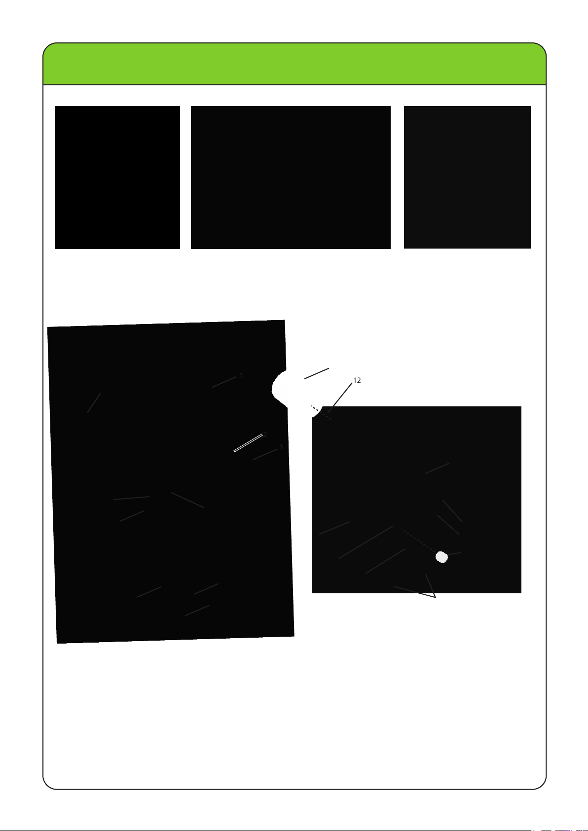
BASIC COMPONENTS
NOTE: May not be exactly as shown, also may not be included as st andard equipment on all models.
11
19
19
12
13
10
14
20
15
17
16
1
2
3
9
8
7
4
5
6
1. TOP COVER
2. TOP COVER LOCK L EVER
3. CARRYING HA NDLE
4. STEERING FRI CTION SCREW
5. ANTI-CAVITATION PLATE
6. PROPELLER
7. COOLING WATER INLET
8. TRIM R OD
9. CLAMP BRAC KET
10. THROTTLE FRICTION AD JUSTER
11. THROTTLE LEVER / TILLER HANDLE
12. BOTTLE BRACKET CLAM P
13. PULL START HANDLE
14. ENGINE SHUT-OFF SWITCH
15. REMOTE PROPANE C ONNECTOR
16. CLAMP SCREWS
17. ROPE ATTACHMENT
18. GEAR SHIFT LEVER
19. RUBBER TANK PLUG
20. BRASS CONNECTOR PLUG
LEHR | ALL RIGHTS RESERVED 2012-2013
3
Page 6
GENERAL INFORMATION
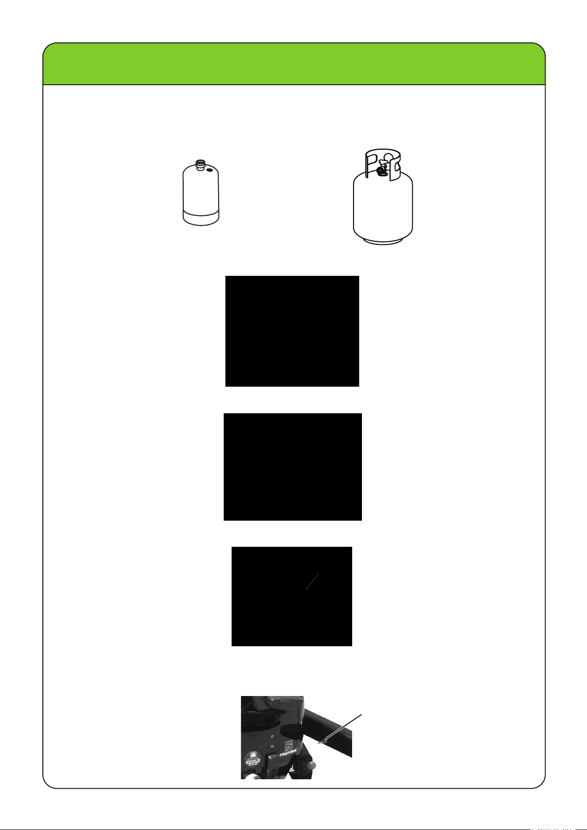
FUEL TANK
Use a standard 16.4 oz. (1 lb.) propane canister connected to the rear propane tank position or any larger
DOT approved propane tank connected to the remote propane connector with an approved high pressure
propane hose. Do not use a hose assembly that includes a pressure regulator.
16.4 OUNCE
1 LB. / 465 GRAMS
TILLER HANDLE
To change direction, move the tiller handle to the left or right as necessary.
REMOTE PROPANE TANK
GEAR SHIFT LEVER
Your outboard has two gear shift positions to provide operation: Forward(F), Neutral(N), and Reverse(R).
Reduce throttle speed to idle speed. Always shift outboard into gear with a quick motion.
THROTTLE GRIP
The throttle grip is on the tiller handle. Turn the grip counterclockwise to increase speed and clockwise to
decrease speed.
THROTTLE GRIP
THROTTLE FRICTION ADJUSTER
A friction device provides adjustable resistance to movement of the throttle grip or the remote control lever,
and can be set according to operator preference. To increase resistance, turn the adjuster clockwise. To
decrease resistance, turn the adjuster counterclockwise.
THROTTLE FRICTION
ADJUSTER
4
LEHR | ALL RIGHTS RESERVED 2012-2013
Page 7
GENERAL INFORMATION
WARNING: Do not overtighten the throttle friction adjuster. If there is too much resistance, it could be
difficult to move throttle lever or grip, which could result in an accident. When constant speed
is desired, tighten the adjuster just enough to maintain the desired throttle setting.
ENGINE STOP SWITCH
The stop switch lock must be attached to the engine stop switch for the engine to run. The hook should be
attached to a secure place on the operators clothing, or arm or leg. Should the operator fall over board or
leave the helm, the hook will pull out the stop switch lock, stopping ignition to the engine. This will prevent
the boat from running away under power.
ENGINE STOP SWITCH
ENGINE STOP SWITCH LANYARD
WARNING: Attach the engine stop switch hook to a secure place on your clothing, or your arm or leg
while operating. Do not attach the hook to clothing that could tear loose. Do not route the
lanyard where it could be come entangled, preventing it from functioning. Avoid accidentally
pulling the lanyard during normal operation. Loss of engine power means the loss of most
steering control. Also, without engine power, the boat could slow rapidly. This could cause
people and objects in the boat to be thrown forward.
NOTE: The engine cannot be started with the stop switch lock removed.
ENGINE STOP SWITCH LOCK
HOOK
ENGINE STOP BUTTON
To stop the engine, push and hold this button or pull the lanyard out from the switch.
ENGINE STOP
BUTTON
MANUAL STARTER HANDLE
To start the engine, first gently pull the handle out until resistance is felt. From that position, then pull the
handle straight out quickly to crank the engine.
STEERING FRICTION ADJUSTER
A friction device provides adjustable resistance to the steering mechanism, and can be set according to
operator preference. An adjusting screw or bolt is located on the swivel bracket.
To increase resistance, turn the adjuster clockwise. To decrease resistance, turn the adjuster
counterclockwise.
:
WARNING
steer, which could result in an accident.
Do not overtighten the friction adjuster. If there is too much resistance, it could be difficult to
LEHR | ALL RIGHTS RESERVED 2012-2013
5
Page 8
GENERAL INFORMATION
TRIM ROD
The position of the trim rod determines the angle of the outboard motor in relation to the transom
TILT LOCK MECHANISM
The tilt support lock keeps the outboard motor in the tilted up position. If the outboard engine needs to be
tilted up out of the water or to get the propeller higher than the bottom of the boat, push down on the tiller
handle while lifting up in the rear carrying handle. Once the engine is all the way up, the tilt lock mechanism
will engage and lock the engine in the up position. To release the lock to lower the engine pull up on the
rear carrying handle to lift the engine up as far as it will go. While the engine is all the way up, lift up on the
lock lever to disengage it while lowering the engine.
TILT LOCK LEVER
.
WARNING: Do not use the tilt support bar when trailering the boat. The outboard motor could shake loose
from the tilt support and fall. If the motor cannot be trailered in the normal running position, use
an additional support device to secure it in the tilt position.
TOP COVER LOCK LEVER
To remove the engine top cover, remove the 1 lb. propane tank or rubber plug. Pull the lock levers upwards
from the bottom and unhook from the top cover. Then lift the cover. When installing the cover, check to be
sure it fits properly on the rubber seal. Then lock the cover by moving the levers downward.
LOCK
LEVER
CARRYING HANDLES
Carrying handles are provided on the front and rear of the outboard motor. The handles enable you to carry
the outboard motor easily with two hands.
FRONT
CARRYING
HANDLE
REAR
CARRYING
HANDLE
6
LEHR | ALL RIGHTS RESERVED 2012-2013
Page 9
INSTALLATION
INSTALLATION
Incorrect engine height or obstructions to smooth water flow in front of the propeller can cause propeller
cavita tion while the boat is cruising. Cavitat ion occurs when the engine speeds up momentarily and suddenly
slows as the propeller engages the water. Severe engine damage may result if the motor is operated
continuously while cavit ating. During water testing check the buoyancy of the boat, at rest, with its maximum
load. Check that the static water level on the exhaust housing is low enough to prevent water entry in to the
power head, when water rises due to waves when the outboard is not running.
MOUNTING THE OUTBOARD MOTOR
• Overpowering a boat could cause severe instability. Do not i nstall an outboard motor with more horsepower
than the maximum rating on the capacit y plate of the boat. If the boat does not have a capacity plate,
consult the boat manufacturer.
• This section is int ended as reference only. It is no
possible boat and motor combinat ion. Proper mounting depends in part on experience and the specific boat
and motor combination. Improper mount ing of the outboard motor could result in hazardous conditions, or
poor handling, loss of control, or boat damage.
• Your dealer or ot her person experienced in proper out board m otor mountings should show you how to
mount your motor. Mount the outboard mot or on the center line (keel line) of the boat, and ensure that the
boat itself is well balanced. Otherwise the boat will be hard to steer. For boats without a keel or which are
asymmetrical, consult your dealer.
aa
t possible to provide complete instructions for every
ANTI-CAVITATION PLATE
CENTER LINE
(KEEL LINE)
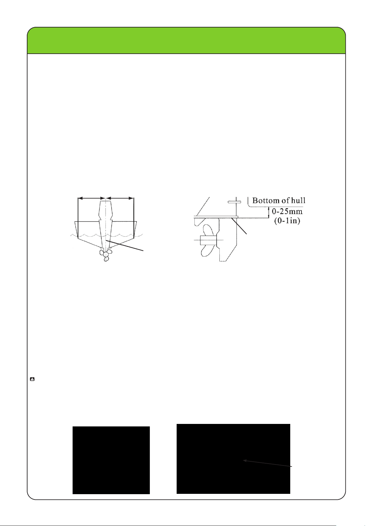
MOUNTING HEIGHT
To run your boat a t best efficiency, the water resistance (drag ) of the boat and outboard motor must be
made as little as possible. The mount ing height of the outboard motor greatly affect s the water resistance.
If the mounting
tips cut the air, the engine speed will rise abnormally and cause the engine to over heat. If the mounting
height is too low, the water resistance will increase and thereby reduce engine efficiency. Mount th e
outboard motor so that the ant i-cavitation plate is between the bottom of the boat and a level 25mm (1in.)
below it.
The optimum mounting height of the outboard motor is affected by the boat and motor combination and the
desired use. Test runs at different heights can help determine the opt imum mounting height. Consult your
boat manufacturer for further informat ion on determining the proper mounting height.
CLAMPING THE OUTBOARD MOTOR
1. Place the outboard motor on the transom so that it is positioned as close to the center as possible. Tighten
the transom clamp screws evenly and securely. Occasionall y check the clamp screws for tightness during
operation of the outboard motor because they could become loose due to engine vibration.
WARNING: Loose clamp screws could allow the outboard motor to f all off or move on the transom. This could
cause loss of cont rol and serious injury. Make sure the transom screws are tight ened securely.
Occasionally check the screws for tightness during operation.
2. If an engine restraint cable or chain attac hment is equipped on your boat, the cable or chain should be
used. Attach one end of the engine restraint cable attachment to the engine clamp and the other to a
secure mounting point on the boat. Otherwise the engine could be completely lost i f it accidentally falls
off the transom.
height is too high, cavitation tends to occur, thus reducing the propulsion, and if the propeller
RESTRAINT CABLE
LEHR | ALL RIGHTS RESERVED 2012-2013
7
Page 10

OPERATION
PRE-OPERATION CHECKS
WARNING: If anything in the pre-operation check is not working properly, have it inspected and repaired
before operating the outboard motor. Failure to do so could result in an accident.
CONTROLS
• Check throttle, shift, and steering for proper operation before starting the engine.
• The controls should work smoothly, without binding or unusual free play.
• Look for loose or damaged connections.
• Check operation of the starter and stop switches when the outboard motor is in the water.
• If the engine has not been used in some time, rev it in neutral to be sure it returns to idle before putting it
in gear.
ENGINE
• Check the engine and engine mounting.
• Look for loose or damaged fasteners.
• Check the propeller for damage.
CHECKING THE ENGINE OIL LEVEL
1. Put the outboard motor in an upright position (not tilted).
2. Screw the oil dipstick all the way in. Unscrew it and check the oil level using the oil dipstick to be sure
the level falls between the upper and lower marks. Fill with oil if it is below the lower mark, or drain to
the specified level if it is above the upper mark.
OIL DIPSTICK
UPPER LEVEL MARK
OIL DIPSTICK
Recommended engine oil:
4-stroke motor oil with a combination of the following SAE and API oil classifications
Engine oil type SAE:
10W-30
Engine oil grade API:
SE,S F, SG, SH, SJ, SL
Engine oil quantity:
0.53USqt (0.5L)
WARNING: ALL ENGINES ARE SHIPPED FROM THE FACTORY WITHOUT ENGINE OIL.
ADD OIL BEFORE STARTING ENGINE.
LOWER LEVEL MARK
FUEL
• Check to be sure you have plenty of fuel for your trip.
• Make sure there are no fuel leaks or propane fumes.
FUELING INSTRUCTIONS
WARNING: PROPANE AND ITS VAPORS ARE HIGHLY FLAMMABLE AND EXPLOSIVE!
• Stop engine before refueling.
• Do not smoke when refueling, and keep away from sparks, flames, or other sources of ignition.
• Refuel in a well-ventilated area.
• Refuel portable fuel tanks off the boat.
USE THE CORRECT PROPANE CANISTER
Always use propane canisters or “bottles” that are the correct size. The 17 ounce or 16.4 ounce / 465g
canisters that are approximately 3-7/8 inches (9.5 cm) in diameter are the correct canisters.
NOTE: Do not use smaller diameter canisters as they will not latch securely to the unit and vibration may
cause damage to the unit and potentially result in a dangerous leak.
8
LEHR | ALL RIGHTS RESERVED 2012-2013
Page 11

OPERATION
INSTALLING THE PROPANE CANISTER
1. Make sure the engine is off.
2. If the propane canister to be installed has a protective plastic cap over the threaded end, remove it.
Make sure the canister clamp is in the unlatched position. If the rubber tank plug is in place, remove it.
Save the plug for future use.
3. Pull the propane connector out from the bottle bracket through the canister clamp.
4. Insert the propane connector onto the threaded end of the canister and screw it clockwise onto threads.
Screw it until snug. Do not over tighten.
NOTE: It may be normal to hear or smell a slight momentary leak of propane as the connector is being
screwed in. Make sure that the connector is installed tight enough that any leakage stops.
Hand tight is sufficient.
5. Insert the connected propane canister through the canister clamp and against the bottle bracket until it
stops against it.
6. Latch the canister clamp closed.
CLAMP
BOTTLE BRACKET
CONNECTOR
CANISTER
REMOVING THE PROPANE CANISTER
1. Make sure the engine is off.
2. Unlatch the canister clamp, pull the canister out, and remove the propane connector by turning it
counterclockwise.
3. Remove the empty canister.
4. Dispose of empty propane canisters in accordance to Federal, State and Local regulations.
CONNECTING REMOTE PROPANE TANK
1. Make sure the engine is off and the propane tank is closed.
2. Connect the remote hose to the remote propane tank. Use only a high pressure propane hose. Do not
use a hose with a regulator attached.
3. Unscrew the brass connector plug from the remote propane connector on the engine. Connect the remote hose to
the remote propane connector.
REMOTE HOSE
REMOTE PROPANE TANK
4. If the engine is intended to be operated solely on the larger remote tank, insert the brass connector plug into the
rear propane connector for the small bottle and install the provided rubber tank plug, and clamp it into place.
REMOTE
CONNECTOR
RUBBER TANK PLUG
NOTE: When a new hose from a remote tank is being used, it may
take a few seconds for the propane to flow to reach the engine.
The engine may start and then die, or not start immediately.
A few extra pulls of the starter are usually sufficient for the flow
to reach the engine.
LEHR | ALL RIGHTS RESERVED 2012-2013
BRASS CONNECTOR PLUG
9
Page 12

OPERATION
STARTING ENGINE
1. Place the gear shift lever in neutral. The engine is equipped with a lockout which will prevent the stater
rope from being pulled if the engine is engaged in forward or reverse.
WARNING: Keep hands, hair, and clothing away from rotating parts while the engine is running. Do not
touch or remove electrical parts when starting or during operation.
2. Attach the stop switch lanyard to a secure place on your clothing, or your arm or leg. Then install the lock
plate on the other end of the lanyard into the engine stop switch.
• Do not attach the lanyard to clothing that could tear loose. Do not route the lanyard where it could become
entangled, preventing it from functioning.
• Avoid accidentally pulling the lanyard during normal operation. Loss of engine power means the loss of
most steering control. Also, without engine power, the boat could slow rapidly. This could cause people
and objects in the boat to be thrown forward.
GEAR SHIFT LEVER
3.
Place
the
a turn faster than the “start” or Idle position.
throttle
4. Pull the manual starter handle slowly until you feel resistance. Then give a strong pull straight out to
start the engine. Repeat if necessary.
5. After the engine starts, slowly return the manual starter handle to the original position before releasing it.
6. Slowly return the throttle grip to the fully closed position.
NOTE: If the engine fails to start after 4 or 5 tries, open the throttle a small amount (between 1/8 - 1/4 throttle)
and try again. Also if the engine is warm and fails to start, open the throttle a small amount and try to
start the engine again. If the weather is below 45 degrees F, open the throttle to 1/4 - 1/2 to start
cold.
grip
in
the
"START" position
THROTTLE GRIP
STOP SWITCH LANYARD
.
If the engine is cold, set the position about 1/8 to 1/4 of
WARMING UP ENGINE
1. Warm up the engine by operating at 1/2 throttle or less for the first 4 minutes. Failure to do so will cause
engine to stall in cold weather, and will shorten engine life.
2. Check for a steady flow of water from the cooling water pilot hole.
NOTE: A continuous flow of water from the cooling water pilot hole shows that the water pump is pumping
water through the cooling passages. If water is not flowing out of the hole at all times while the
engine is running, over heating and serious damage could occur. Stop the engine and check whether
the cooling water inlet on the lower case or the cooling water pilot hole is blocked. Consult your
dealer if the problem cannot be located and corrected.
COOLING WATER
PILOT HOLE
(BOTTOM VIEW OF ENGINE)
10
LEHR | ALL RIGHTS RESERVED 2012-2013
Page 13

OPERATION
SHIFTING
WARNING: Before shifting, make sure no swimmers are in the water near your boat.
1. Place the throttle in the slowest position.
2. Move the gear shift lever quickly to the desired gear from neutral to forward or reverse.
WARNING: When operating your outboard engine in reverse, go slowly. Do not attempt to open the throttle
more than half throttle in reverse. Otherwise your boat can become unstable which can result
in loss of control or a possible accident.
STOPPING ENGINE
1. Push and hold the engine stop button until the engine completely stops.
2. After the engine has stopped disconnect the propane canister.
ADJUSTING BOAT TRIM
WARNING: Stop the engine before adjusting the trim angle. Use care to avoid being pinched when removing
the trim rod. Use caution when trying a trim position for the first time. Increase speed gradually
and watch for any signs of instability or control problems. Improper trim angle can cause loss of
control.
• Tilt the engine up slightly.
• Reposition the rod inside the desired hole.
• To raise the bow (”trim-out”), move the trim rod away from the transom.
• To lower the bow (”trim-in”), move the trim rod closer to the transom.
• Test the boat with the trim set to different angles to find the position that works best for your boat and
operating conditions.
TRIM ROD
NOTE: The outboard motor trim angle can be changed approximately 4 degrees by shifting the trim rod one
hole.
When the boat is on plane, a bow-up attitude results in less drag, greater stability and efficiency. This is
generally when the keel line of the boat is up about 3 to 5 degrees. With the bow up, the bow of the boat may
have a greater tendency to steer to one side or the other. Compensate for this as you steer. The trim tab
can also be adjusted to help to help offset this effect. When the bow is down, it is easier to accelerate from
a standing start onto plane.
BOW UP
Too much trim-out puts the bow of the boat too high in the water. Performance and economy are decreased
because the hull of the boat is pushing the water and there is more drag. Excessive trim-out can also cause
the propeller to ventilate, which reduces performance further, and the boat may “porpoise” (hop in the water)
which could throw the operator and passengers overboard.
LEHR | ALL RIGHTS RESERVED 2012-2013
11
Page 14

OPERATION
BOW DOWN
Too much trim-in causes the boat to “plow” through the water, decreasing fuel economy and making it hard
to increase speed. Operating with excessive trim-in at higher speeds also makes the boat unstable.
Resistance at the bow is greatly increased, heightening the danger of “bow steering” and making operation
difficult and dangerous.
NOTE: Depending on the type of boat, the outboard motor trim angle may have little effect on the trim of the
boat when operating.
TILTING UP AND DOWN
If the engine will be stopped for some time and the boat is moored in shallows, the outboard motor should
be tilted up to protect the propeller and casing from damage from collision with obstructions, and also to
reduce salt corrosion.
WARNING: Before tilting the outboard motor, follow the procedure under “Stopping Engine” in this section.
Never tilt the outboard motor while the engine is running. Sever damage from o verheating can
result. Do not tilt the engine b y pushing the tiller handle bec ause this could break the handle.
Keep the power unit higher than th e propeller at all times otherwise wate r could run into the
cylinder and cause damage. The outboard motor cannot be tilted while in revers e.
WARNING: Be sure all people are clear of the outboard motor when tilting up and down, also be careful not
to pinch any body parts between the drive unit and engine bracket.
PROCEDURE FOR TILTING UP
1. Place th e gear s hifter lever i n neutral and face the ou tboard mo tor forward.
2. Tighten the st eering frict ion adjust er by turning it clock wise to prev ent the motor from turning freely.
3. Hold th e carrying handle and ti lt the engine up fully unti l the t ilt s upport lever automat ically loc ks.
PROCEDURE FOR TILTING DOWN
1. Slightly tilt t he outboard motor up.
2. Slowly ti lt the outboard mo tor down while pulling the til t support lever up .
3. Loosen th e steering friction adjuster by turning it c ounterclockwise, and adjust the st eering frict ion
accordin
g to opera tor pre ference.
STEERING FRICTION
ADJUSTER
TILT SUPPORT
LEVER
12
LEHR | ALL RIGHTS RESERVED 2012-2013
Page 15

MAINTENANCE
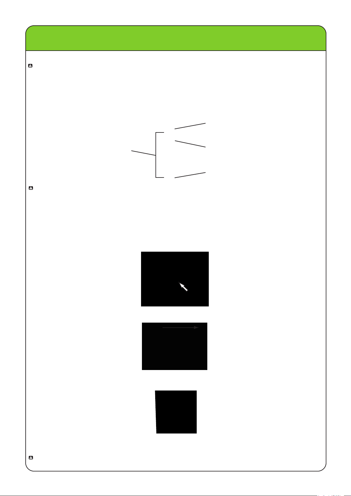
TRANSPORTING AND STORING THE OUTBOARD MOTOR
WARNING: Leaking fuel is a fire hazard. When transporting or storing the outboard motor, disconnect the
propane connector to prevent the possibility of fuel from leaking. Use care when transporting
the fuel tank whether in boat or car.
Never get under the lower unit while i t is tilted, even if a motor support bar is used. Severe injury could occur
if the outboard motor accidentally falls.
Do not use the tilt support lever when trailering the boat. The out board motor could shake loose from the tilt
support and fall. If the motor can not be trailered in the normal running position, use an additional support
device to secure it in the tilt position.
The outboard motor should be trailered and st ored in the normal running posit ion. If there is insufficient road
clearance in this position, then trailer the outboard motor in the tilt position using a motor support device such
as a transom saver bar.
When transporting or st oring the outboard motor while removed from a boat, keep the outboard motor
in the attitudes shown.
CARRY FROM THE HANDLES
STORE WITH THE HANDLE SIDE DOWN
STORE IN THE UPRIGHT POSITION
LEHR | ALL RIGHTS RESERVED 2012-2013
13
Page 16

MAINTENANCE
STORING THE OUTBOARD MOTOR
NOTE: Place a towel or something similar under the outboard motor to protect it from damage.
When storing your outboard motor for prolonged periods of time (2 months or longer), several important
procedures must be performed to prevent excessive damage.
NOTE: Cooling system flushing is essent ial to prevent the cooling syst em from clogging up with salt sand,
or dirt. In addition, fogging / lubricating of the engine is mandat ory to prevent excessive engine
damage due to rust. Perform the flushing and fogging at the same time.
• To prevent problems which can be caused by oil ent ering the cylinder from the sump, keep the outboard
motor in the attit ude shown when transporting and storing it. If storing or transporting the outboard motor
on its side (not upright), put it on a cushion after draining the engine oil.
• Do not place the outboard motor on it s side before the cooling wat er has drained from it complet ely,
otherwise water may ent er the cylinder through the exhaust port and cause engine trouble.
• Store the outboard motor in a dry, well vent ilated place, not in direct sunlight.
PROCEDURE FOR FLUSHING AFTER SEA WATER USE
If the engine has been operated in saltwater, it should always be flushed with fresh water after each use before being
stored. Do
damaged
water to the cooling water passages.
1. Wash the out board motor body using fresh water.
2. Remove the engine top cover.
3. Install the outboard mot or on a test tank, or submerge the drive in water in some way, as long as the
outboard is safely and securely mounted to a solid object.
4. Fill the tank with fresh wat er to above the level of the anti-cavitation plate. If the freshwater level is
below the level of the anti-cavit ation plate , or if the water supply is insufficient, engine seizure may
occur.
5. Run the engine at a fa st idle for a few minutes in neutral position.
not
run
the
or
the engine will be damaged from overheating. Be fore starting the engine, be sur e to supply
engine
without
supplying
it
with
cooling
water.
Either
the
engine
water
pump
will
be
WARNING: Never engage forward gear if engine is running when not attached to a boat. An exposed,
spinning propeller is dangerous. Even in a tank, the engine can suddenly move when shifted
into gear causing the tank or motor to shift and expose the propeller which could result in
serious injury.
NOTE: Do not touch or remove elect rical parts when starting or during operation. Keep hands, hair, and
clothes away from the flywheel and ot her rotating parts while the engine is running.
6. Remove the out board motor from the test tank.
7. Install the top cover
8. Drain the cooling water complet ely out of the motor. Clean t he body thoroughly.
.
WATER SURFACE
LOWEST WATER LEVEL
ANTI-CAVITATION PLATE
14
LEHR | ALL RIGHTS RESERVED 2012-2013
Page 17

MAINTENANCE
LUBRICATION
1. Remove the spark plug and spray some fogging oil into the cylinder.
2. Grease the spark plug threads and install the spark plug and torque to proper specification.
3. Change the gear oil. Inspect the oil for the pres ence of water that indicates a leaky seal.
4. Grease all grease fittings.
CLEANING THE OUTBOARD MOTOR AFTER USE
1. After use wash the exterior of the outboard mot or with fresh water.
2. Flush the cooling syst em with fresh water.
CHECKING PAINTED SURFACE OF MOTOR
1. Check the motor for scratches, nicks, or flaking paint. Areas with damaged paint are more likely to
corrode. If necessary, clean and paint the areas.
NOTE: Be sure to turn o ff the engine when you perform maintenance unless otherwise specified. If you or
the owner are not familiar with machine servicing, this work should be done by your LEHR dealer
or other qualified mechanic.
REPLACEMENT PARTS
If replacement parts are necessary, use only genuine LEHR parts or parts of the same type and of
equivalent strength and materials. Any part of inf erior quality may malfunction, and the resulting loss of
control could endanger the operator and passengers. LEHR genuine parts and accessories are available
from your LEHR dealer, or directly from LEHR.
MAINTENANCE CHART
Frequency of maintenance operat ions may be adjusted according to the operating condit ions, but the
following table gives general guidelines. Refer to the sections in this chapter for explanat ions of each
owner-specificaction. When operating in salt wat er or dirty water, the engine should be flushed wit h clean
water after each use.
The “ ” symbol indicat es the check-ups which you may carry out yourself.
•
The “ ” symbol indicat es work to be carried out by your LEHR dealer.
Item Actions
Anodes(s)
Cooling water passages
Cover clamps Inspection
Fuel system Inspection
Gear oil Change
Greasing points
Idling speed Inspection /adjustment
Propeller and cotter pin Inspection/replacement
Shift link Inspection/adjustment
Thermostat Inspection/replacement
Throttle link/throttle
cable/ throttle
Water pump Cleaning/adjustment/replacement
Engine oil Inspection/change
Spark plug(s) Inspection/adjustment/replacement
Inspection/replacement
Cleaning
Greasing
Inspection/adjustment
Initial Every
10 hours 50 hours 100 hours 200 hours
(1
month)
(3
months )
( 6 months)
(
1
year)
Valve clearance Inspection/adjustment
LEHR | ALL RIGHTS RESERVED 2012-2013
15
Page 18

MAINTENANCE
GREASING
NOTE: Use only water resist ant grease.
Grease in these areas:
SPARK PLUG
WARNING: When removing or installing a spark plug, be caref ul not to damage the insulator. A damaged
insulator could allow ext ernal sparks, which could lead to explosion or fire.
The spark plug is an important engine part and is easy to inspect. The condition of the spark plug can
indicate the condition o f the engine. Normally, the spark plug in a propane engine will stay very clean.
Oily or dark color ceramic could indicate a malfunction. Do not attempt to diagnose any problems yourself.
Instead, take the outboard mot or to a L EHR dealer. You should periodically remove and inspect the spark
plug because the electric arcing will cause the spark plug to slowly erode and the gap will increase.
If electrode erosion becomes excessive, or i f carbon and other deposits are excessive, you should replace
the spark plug with another of the correct type.
Before fitting the spark plug, measure the electrode gap with a wire thickness gauge. Adjust the gap to
specific ation if necessary.
Spark plug ID mark (i.e. NGK)
Standard spark plug: BR6H8
Spark plug gap:
0.020-0.024in (0.5-0.6mm)
Spark plug torque:
l8.4ft-lb (25.0Nm)
Spark plug Boot
When fitting the plug, always clean the gasket surf ace and use a new gasket. Wipe off any dirt from the
threads and screw in the spark plug to the correct torque.
NOTE: If a torque-wrench is not available when you are fitting a spark plug, a good estimate o f the correct
torque is 1/4 to 1/2 a turn past finger tight. Have the spark plug adjusted to the correct torque as
soon as possible with a torque wrench.
INSPECTION CHECKPOINTS
Periodically check the fuel system for leaks. With the propane tank attached, and the engine cover removed,
inspect the following fuel system parts for leakage. Leaks can be identified by smell of propane or carefully
listening for a hissing sound of escaping gas. Suspected leaks can be verified by applying soapy water
solution on the area and observing bubbles forming.
16
LEHR | ALL RIGHTS RESERVED 2012-2013
Page 19

MAINTENANCE
NOTE: Inspect the following for any source of a fuel leak.
• Fuel system parts leakage
• Fuel line joint leakage
• Fuel line cracks or other damage
• Fuel connector leakage
ADJUSTING IDLING SPEED
WARNIN G: Do not t ouch or remove elec trical part s when s tarting or during operation. Keep hands, hair ,
and clo thes away from the flywheel and other rotat ing parts while the engine is running.
CAUTION: T his procedure must be performed while the o utboard m o tor is in th e water . A flushing
NOTE: A diagnostic tachome ter should be us ed for this procedu r e. Resul ts may vary depending on whether
testing is conduc ted wit h the f lushing at tachment , in a t est tank, or wit h the o utboard m otor in the
water .
1. S
tart the engine and allow it to warm up f ully in neutral u n til it is running smoothly.
NOTE: Correct idling speed ins pection i s only possible if the engine is fully warmed up. If not warmed up
fully, the idle speed will measure higher than nor m al. If yo u have difficu lty verif ying th e idle s peed
2. Verify whether t he idle speed is s et to speci ficat ion (200 0 150 RPM) . Adjust the speed by turning th e
idle speed screw wi th a phillips head screw driver as sho w n.
attachment or test tank can be used.
,
or the idle speed requires adjust ment, consult a LE H R dealer o r other quali fied mechanic.
+
CARBURETOR
IDLE SPEED SCREW
CHANGING ENGINE OIL
WARNIN G: Avoid draining the engine oil immediat ely aft er stop p ing the engine. The oil is h ot and should
be handled with care to a void burns.
• Be sure the outboard mo tor is securely fastened to the transom or a st able stand .
• Do n ot overf ill the oil , and b e sure th e out board motor is up right (not t ilted) when checking and changing
the engine oil.
• If the oil level is above the upper leve l mark, drain until the lev el meet s the s pecified capacity. Ov erfilling
the oil could cause leakage or damage.
• Change th e engine oil afte r the f ir
thereafter . Otherwise th e engine will wear quickly .
st 10 hours of operation, and every 100 hours o r at 6 month i ntervals
NOTE: Change th e engine oil when th e oil is still warm .
OIL DRAIN PLUG
TORQUE TO 10 lb/ft (13.6 N-m)
(BOTTOM VIEW OF ENGINE)
1. Put the outboard mot or in an upright position (not tilted).
2. Prepare a suitable container that holds a larger amount than the engine oil capacity. Loosen and remove
the drain plug while holding the cont ainer under the drai n hole. The oil drain plug is located on the
bottom of the engine near the shift lever. Use a 13 mm socket wrench. Then remove the oil filler cap.
Let the oil drain completely. Wipe up any spilled oil immediately.
3. Put a new gasket on the oil drain plug. Apply a light coa t of oil to the gasket and install the drain screw.
NOTE: If a torque wrench is not available when you are install ing the drain screw, finger tighten the screw
just until the gasket comes in contact wit h the sur face of the drain hole. Then tighten 1/4 to 1/2 turn
more. Tighten the drain screw to the correct torqu e with a torque wrench as soon as possible.
4. Add the correct amount of oil through the filler hole. Ins t all the filler cap.
LEHR | ALL RIGHTS RESERVED 2012-2013
17
Page 20

MAINTENANCE
5. Make sure that there are no oil leaks. Continued operat ion with an oil leak could cause severe engine
damage.
6. Turn off the engine and wait 3 minutes. Recheck the oil level using the oil dipstick to be sure the level
falls between the upper and lower marks when the dipstick is screwed in all the way. Add oil if the level
is below the lower mark, or drain to the specified level if it is above the upper mark (see pg 8).
7. Dispose of used oil according to local regulat ions.
NOTE: Change the oil more often when operating the engine under adverse conditions such as extended
trolling.
Recommended engine oil: 10W - 30
4-stroke outboard motor oil
Engine oil quantity:
0.5L (0.53
US
qt)
OIL DIPSTICK
CHECKING WIRING AND CONNECTORS
• Check that each grounding wire is properly secured.
• Check that each connector is engaged and secured.
EXHAUST LEAKAGE
Start the engine and check that no exhaust leaks from the joint s between the exhaust cover, cylinder
head, and cylinder.
WATER LEAKAGE
Start the engine and check that no water leaks from the joints between the exhaust cover, cylinder head,
cylinder, thermostat housing, and thermostat hose.
CHECKING PROPELLER
WARNING: You could be seriously injured if the engine accident ally starts when you are near the propeller.
Before inspecting, removing, or installing the propeller, remove the spark plug cap from the
spark plug. Also, place the shift control in neutral, and remove the lanyard from the engine stop
switch.
•
Check each of the propeller blades for wear, erosion from cavitation, or other damage.
• Check the propeller shaft for damage.
• Check the splines for wear or damage.
• Check for fish line tangled around the propeller shaft.
• Check the propeller shaft oil seal for damage.
REMOVING THE PROPELLER
1. Straighten the cotter pin and pull it out using a pair of pliers.
2. Remove the propeller nut and washer.
3. Remove the propeller and thrust washer.
1
2
3
4
1. COTTER PIN
2. PROPELLER NUT
3. WASHER
4. PROPELLER
5. THRUST WASHER
6
5
6. PROPELLER SHAFT AND SPLINES
18
LEHR | ALL RIGHTS RESERVED 2012-2013
Page 21

MAINTENANCE
WARNING: Do not use your hand to hold the propeller when loosening or tightening the propeller nut. Put
a wood block between the anti-cavitation plate and the propeller to prevent the propeller from
turning.
ANTI-CAVITATION PLATE
WOOD BLOCK
PUT A WOOD BLOCK BETWEEN THE PROPELLER AND
THE ANTI-CAVITATION PLATE TO KEEP IT FROM TURNING
INSTALLING THE PROPELLER
• Be sure to inst all the thrust washer before installing the propeller, otherwise the lower case and propeller
boss could be damaged.
• Be sure to use a new cotter pin and bend the ends over secure ly. Otherwise the propeller could come
off during operation and be lost.
1. Apply corrosion resistant grease to the propeller shaft.
2. Install the thrust washer, and propeller on the propeller shaft.
3. Install the washer. Tighten the propeller nut until there is no forward-and-backward movement.
4. Align the propeller nut with the propeller shaft hole. Ins ert a new cotter pin in the hole and bend the
cotter pin ends.
NOTE: If the propeller nut does not align wit h the propeller shaft hole after tight ening it, loosen the
nut until it aligns with the hole.
COTTER PIN
PROPELLER SELECTION
Your LEHR outboard engine is supplied with a propeller that matches the needs of a boat most suited to an
engine of its size. If you feel you are not getting optimal performance from the engine on your boat, a
different pitch propeller could help. The performance of your outboard motor will be affected if you choose a
different propeller, as an incorrect choice could adversely affect performance and could also seriously damage
the motor. Engine speed depends on the propeller size and boat load. If engine speed is too high or too low
for good engine performance, this will have an adverse effect on the engine. For a greater operating load, a
smaller-pitch propeller is more suitable as it enables the correct engine speed to be maintained. Conversely,
a larger-pitch propeller is more suitable for a smaller operation load.
X
1 2 3
1. Propeller diameter in inches.
2. Propeller pitch in inches.
3. Type of propeller (propeller mark).
NOTE: Select a propeller which will allow the engine to reach the middle or upper half of the operation range
at full throttle with the maximum boat load. In operation conditions such as light boat loads, do not
allow the engine RPM to rise above the maximum recommended range, reduce the throttle setting to
maintain the engine in the proper operation range.
LEHR | ALL RIGHTS RESERVED 2012-2013
19
Page 22

MAINTENANCE
Oil leveI plug
Gear oil drain screw
CHANGING GEAR OIL
• Be sure the outboard motor is securely fastened to the transo m or a st able stand. You could be severely
injured if the outboard mot or falls on you.
• Never get under the lower unit while it is tilted, even when the tilt support lever or knob is locked.
Severe injury could occur if the outboard motor accident ally falls.
1. Tilt the outboard motor so that the gear oil drain screw is at the lowest point possible.
2. Place a suitable container under the gear case.
3. Remove the gear oil drain screw.
Recommended
Hypo id
Gear
oil
2.54
NOTE: If a magnetic gear oil drain screw is equipped, remove all metal particles from the screw bef ore
installing it.
• Always use new gaskets .
• Do not reuse the removed gasket s.
4. Remove the oil Ievel plug to allow the oil to drain completely. Inspect the used oil after it has been
drained. If the oil is milky, water is getting into the g ear case which can cause gear and bearing damage.
Consult your LEHR dealer for repair of the lower unit seals.
5. With the out board motor in a vert ical position and using a flexible or pressurized filling device, inject the
gear oil into the gear oil drain screw hole.
6. When the oil begins to flow out o f the oil level plug hole, insert and tighten the oil level plug.
7. Insert and tighten the gear oil drain screw.
gear
quan tity
US fl.
gear
oil
oz. (
oil:
SAE#90
:
75.0
mL)
INSPECTING AND REPLACING ANODE
LEHR outboard mot ors are protected from corrosion by a sacrificial anode. Inspect the ext ernal anode
periodically. Remove scales from the surfaces o f the anode. Do not paint the anode, as this would render
it ineffective.
ANODE
ANODE
COATING THE BOAT BOTTOM
A clean hull improves boat performance. The boat bottom should be kept as clean of marine growt h as
possible. If necessary, the boat bottom can be coat ed with an anti-fouling paint approved for your area
to inhibit marine growth . Do not use anti-fouling paint which includes copper or graphite. These paints
can cause more rapid engine corrosion.
20
LEHR | ALL RIGHTS RESERVED 2012-2013
Page 23

TROUBLESHOOTING
A problem in the fuel, compression, or ignition systems can cause poor starting, loss of power, or other
problems. This section describes basic checks and possible remedies.
ENGINE WILL NOT START OR OPERATE
Q: Is engine stop switch lanyard not attached?
A: Attach lanyard.
Q: Is throttle speed set incorrectly?
A: Set throttle speed to 1/4 or less, unless the water is cold, then set to 1/4 - 1/2 throttle. See pg 10.
Q: Is shift lever in gear?
A: Shift to neutral.
Q: Is propane tank empty, or fully connected?
A: Shake the tank to feel for liquid, then be sure it is fully connected.
Q: Is the spark plug fouled or incorrect type?
A: Inspect spark plugs. Clean or replace with recommended type.
Q: Is spark plug cap fitted incorrectly?
A: Check and re-fit caps.
Q: Is ignition wiring damaged or poorly connected?
A: Check wires for wear or breaks. Tighten all loose connections. Replace worn or broken wires.
Q: Possible faulty ignition parts?
A: Have serviced by LEHR dealer.
Q: Possible faulty internal engine parts?
A: Have serviced by a LEHR dealer.
ENGINE IDLES IRREGULARLY OR STALLS
Q: Is propane tank empty?
A: Check tank fluid level by shaking it.
Q: Is spark plug fouled or incorrect type or gap?
A: Inspect spark plug. Clean or replace with recommended type.
Q: Is the Idle speed set correctly?
A: Adjust Idle screw or have serviced by LEHR dealer.
Q: Are fuel joints connected correctly?
A: Check for any leaks or smell of propane. Tighten any loose fittings. Replace any faulty fuel lines or
connectors.
Q: Is thermostat faulty or clogged?
A: Have serviced by LEHR dealer.
Q: Is carburetor faulty?
A: Have serviced by LEHR dealer.
Q: Is engine oil level low?
A: Check oil level and add oil if needed.
ENGINE POWER LOSS
Q: Is fuel supply running low?
A: Shake propane bottle or tank to determine if propane level is low. If so, replace tank or operate at reduced
throttle settings until fuel supply is replenished.
Q: Is fuel system obstructed?
A: Check for pinched or kinked fuel line or other obstructions in fuel line.
Q: Is propeller damaged?
A: Have propeller repaired or replaced.
Q: Is propeller pitch or diameter incorrect?
A: Install correct propeller to operate outboard at its recommended speed.
LEHR | ALL RIGHTS RESERVED 2012-2013
21
Page 24

TROUBLESHOOTING
Q: Is trim angle correct?
A: Adjust trim angle to achieve most efficient operation.
Q: Is motor mounted at incorrect height on transom?
A: Have motor adjusted to proper transom height.
Q: Is boat bottom fouled with marine growth?
A: Clean bottom of boat.
Q: Are weeds or other foreign matter Tangled on gear housing?
A: Remover foreign matter and clean power unit.
Q: Is spark plug gap incorrect?
A: Inspect and adjust as specified.
Q: Is ignition wire damaged or poorly connected?
A: Check wires for wears and breaks.
Q: Have electrical wires failed?
A: Have serviced by a LEHR dealer.
ENGINE VIBRATES EXCESSIVELY
Q: Is propeller damaged?
A: Have propeller repaired or replaced.
Q: Is propeller shaft damaged?
A: Have serviced by a LEHR dealer.
IMPACT DAMAGE
WARNING: The outboard motor can be seriously damaged by a collision while operating or traveling.
Damage may make the outboard motor unsafe to operate.
If the outboard motor hits an object in the water, follow the procedure below.
1. Stop the engine immediately.
2. Inspect the control system and all components for damage. Also inspect boat for damage.
3. Whether damage is found or not, return to the nearest harbor slowly and carefully.
4. Have the outboard motor inspected before operating it again.
STARTER WILL NOT OPERATE
If the start mechanism does not operate (the engine cannot be cranked with the starter), the engine can be
started with an emergency starter rope.
WARNING:
• Use this procedure only in an emergency and only to return to the port for repairs.
• Make sure the gear shift lever is in neutral. Otherwise the boat could unexpectedly start to
move, which could result in an accident.
• Attach the engine stop switch lanyard to a secure place on your clothing, or your arm or leg while operating.
• Do not attach the lanyard to clothing that could tear loose. Do not route the cord where it could become.
entangled, preventing it from functioning.
• Avoid accidentally pulling the lanyard during normal operation. Loss of engine power means the loss of
most steering control. Also without engine power, the boat could slow rapidly. This could cause people
and objects in the boat to be thrown forward.
• Be sure no one is standing behind you when pulling the starter rope. It could whip behind you and hurt
someone.
• An exposed, rotating flywheel is very dangerous. Keep loose clothing and other objects away when
starting the engine. Do not touch the flywheel or other moving or parts when the engine is running.
22
LEHR | ALL RIGHTS RESERVED 2012-2013
Page 25

TROUBLESHOOTING
EMERGENCY ENGINE START
1. Remove the top engine cover.
2. Remove the starter cover by unscrewing the bolts.
3. Make sure the engine is in neutral and that the switch is attached to the engine shut o ff switch.
4. Insert the knotted end of the emergency starter rope in the notch into the flywheel rotor and wind the rope
several times clockwise.
NOTCH
NOTE: If the rope is too long a fter winding it around the flywheel, shorten at the handle.
5. Pull the rope slowly until resistance is felt.
6. Give a st rong pull out to crank and st art the engine. Repeat if necessary.
PROCEDURE FOR SUBMERGED MOTOR
If the outboard motor has been submerged, immediately take it to a LEHR dealer. Some corrosion may
begin almost immediately. If you cannot immediately take the out board to a dealer, follow the procedures
below in order to minimize engine damage.
1. Wash away mud, salt, seaweed, and debris with fresh water.
2. Remove the spark plug, then face the spark plug hole downward
contaminants to drain.
3. Drain the engine oil completely.
4. Fill the sump with fresh engine oil.
5. Feed small drops of oil throughout carburet or and spark plug hole while cranking the manual starter or
emergency starter rope.
6. Take the out board motor to a L EHR dealer as soon as possible.
NOTE: Do not attempt to run the outboard motor until it has been inspected.
to allow any water, mud, or
LEHR | ALL RIGHTS RESERVED 2012-2013
23
Page 26

SPECIFICATIONS
MODELS LP 5.0S & LP 5.0L
ENGINE TYPE
DISPLACEM ENT
BORE X STROKE 59 mm X 41 mm
POWER 5 hp (3.5 kW)
MAX OPERATING R. P.M.
IDLE SPEED
IGNITION TYPE
IGNITION SWITCH
VALVE CLEARANCE IN and EX (COLD)
SPARK PLUG TYPE
SPARK PLUG GAP
WATER COOLED 4-CYCLE
.003-.005 in (0.08-0. 12mm)
0.020-0.024 INCH (0.5-0.6 mm)
NOTE:
(S) SHORT SHAFT
(L) LONG SHAFT
112.0 CC
4000 - 4500 R. P.M.
2000 R. P.M.
ELECTR ONIC
TETHER
NGK BR 6 H 8
SPARK PLUG TORQUE SPEC
LUBRICATION
CRANKCASE OIL CAPACITY
GEAR OIL CAPACITY
FUEL
STARTER
GEAR SHIFT F – N – R
GEAR RATIO 2.08
TRANSOM HEIGHT 15” (381 mm)(S), 20” (508 mm)(L)
WEIGHT 49.6 lbs (22.5kg) (S), 52.8 lbs (23.9 kg)(L)
PULL CHORD AUTO REWIN D
18.4 ft•lb (25.0 N•m)
4 STROKE 10W-30
0.53 US qt (0.5L)
3.93 fl oz. (0.100L)
PROPANE
24
*ALL SPECIFICATIONS ARE BASED ON THE LATEST PRODUCT INFORMATION AT THE TIME OF PRINTING.
WE RESERVE THE RIGHT TO MAKE CHANGES AT ANY TIME WITHOUT NOTICE.
LEHR | ALL RIGHTS RESERVED 2012-2013
Page 27

MANUFACTURER’S LIMITED WARRANTY
The limited warranty set forth below is given by LEHR with respect to new merchandise purchased and used
in the United States and Canada, its possessions and territories. LEHR warrants to the original purchaser
that each new LEHR brand outboard is free from defects in material and workmanship and agrees to repair
or replace under this warranty any defective product or attachment as follows from the original date of
purchase.
3 YEARS -- Parts and Labor.
90 DAYS -- Parts and Labor, when used for income producing purposes.
30 DAYS -- Parts and Labor, if used for rental purposes.
This warranty is not transferable and does not cover damage or liability caused by improper handling,
improper maintenance, or the use of accessories not specifically recommended by LEHR for this product.
In addition, it does not cover any product that has been subject to misuse, neglect, negligence, or accident,
or has been operated in any way contrary to the operating instructions specified in this operator’s manual.
Additionally, this warranty does not cover tune-ups, spark plugs, carburetor adjustments, starter pulley or
parts that will wear and require replacement with reasonable use during the warranty period. This warranty
does not cover pre delivery setup or normal adjustments explained in the instruction manual. Shipping of
parts is not the responsibility of LEHR.
THIS WARRANTY GIVES YOU SPECIFIC LEGAL RIGHTS, AND YOU MAY HAVE OTHER RIGHTS WHICH
VARY FROM STATE TO STATE. NO CLAIMS FOR CONSEQUENTIAL OR OTHER DAMAGES WILL BE
ALLOWED, AND THERE ARE NO OTHER EXPRESS WARRANTIES EXCEPT THOSE EXPRESSLY
STIPULATED HEREIN. SOME STATES DO NOT ALLOW LIMITATIONS ON HOW LONG AN IMPLIED
WARRANTY LAST OR THE EXCLUSION OR LIMITATIONS OF INCIDENTAL OR CONSEQUENTIAL
DAMAGES, SO THE ABOVE LIMITATIONS OR EXCLUSION MAY NOT APPLY TO YOU.
LEHR does not extend any warranty for products sold or exported outside of the United States or Canada,
its possessions and territories, except those sold through LEHR’s authorized channels of export distribution.
The policy of LEHR is to continuously improve its products. Therefore, LEHR reserves the right to change,
modify, or discontinue models, designs, specifications of all products at any time without notice or obligation
to any purchaser.
HOW TO OBTAIN SERVICE: Warranty service is available, with proof of purchase through your local
authorized service dealer. To locate the dealer in your area, visit our website at www.golehr.com or call
1-866-941-LEHR or write to 8922 Ellis Ave. LA, CA 90034.
CALIFO RN IA EMISSIO NS/EPA CONTR OL WA RRANTY STATE MENT
YOUR W ARRANTY RI GH TS AN D OBL IGATI ONS
The Ca liforni a Air Resources Board, t he Environ mental Pro tecti on Agen cy and LEHR, Inc. are pl eased to
expl ain the emis sions contro l syste m’s w arranty on your 2 012 a nd later marine eng ine. In Cal iforn ia and
the 49 stat es, n ew eq uipment that use marin e engines must be des igned , bui lt, and eq uipped to me et th e
State’ s str ingent antismal l off-road engine for the p eriod l isted belo w provi ded t here has bee n no abuse, negle ct or improp er
mainte nance o f you r eng ine.
Your e missi ons con trol system may inc lude parts such as: ca rbure tors or fu el inje ction system , ign ition
system , cat al ytic conve rters, fuel tanks , valves, filte rs, cla mps, conne ct ors, and o ther as socia ted
compon ents. Als o, in cl uded may be hoses , bel ts, con necto rs, sensors, and other e missi onassemblies.
Where a warra ntabl e con ditio n exi sts, LE HR will repa ir your mari ne en gine at no c ost t o you i nclud ing
diagno sis, parts and la bor.
MANUFACT URER’ S W ARRAN TY COVE RAGE:
This e missi ons control syste m is warranted for ten yea rs. If an y emi ssions-relat ed part on you r equ ipmen t
is def ectiv e, the part wi ll be repa ired or repl aced by LE HR.
smog s tandard s. LEH R, In c. mu st warr ant t he em issio ns cont rol s ys tem o n your
relate d
OWNER’S W AR RANTY R ESPON SIBIL IT IES:
As the marine engi ne ow ner, you are resp onsible fo r perfo rmanc e of the req uired main tenance list ed in
•
your own er’s manual. LEH R recommends that you retain all r eceipts cove ring maintenance on your
marine en gi ne, b ut LEHR cann ot de ny warr an ty so lel y for the lack of receipts or your fail ure to ensure
the perform ance of al l sched uled maint en ance.
• As the marine engi ne ow ner, you sho uld h oweve r be aware t hat L EHR may deny you wa rrant y covera ge if
you r mar ine e ngine or a p art has fa iled due to abuse , neglect, or imp roper m ainte nance or u napprov ed
modifi catio ns.
• You ar e respo nsibl e for p resen ting your ma rine engin e to a LEHR servi ce ce nter as soon as the proble m
exis ts. The w arran ty re pairs s hould be complete d in a reaso nable a mount of t ime, no t to exceed 30 da ys .
f you hav e a que stion regard ing your w arranty cove rage, you should conta ct LEHR at 1-8 66-941-LEHR.
I
LEHR | ALL RIGHTS RESERVED 2012-2013
25
Page 28

MANUFACTURER’S LIMITED WARRANTY
DEFECT S WAR RANTY REQU IR EMENTS:
(a) The wa rrant y per iod b egins on the date the en gine or equi pment is d elivere d to an ul timat e purch aser.
(b)
Genera l Emiss ions Warra nty Cov erage . Th e man ufactur er of each m ari ne engine or equ ipmen t mus t
warrant to th e ult imate purcha ser a nd ea ch subs equ en t own er that the engine or equi pme nt is :
(1) Desi gn ed, b uilt, and eq uip ped so as to confor m wit h all applicable re gulat ions ad opted by t he Ai r
Resou rces Bo ard; and
(2) Free f rom d efect s in materia ls and workm anshi p that cause s the failur e of a warra nte d part for a
perio d of ten yea rs.
The wa rrant y on em issio ns-relate d par ts will be i nterp re ted a s fol lows:
(c)
(1) Any warrant ed pa rt th at is n ot sc heduled for repla cement as re quired maint enance in the writt en
instr uctio ns requ ired by Subs ectio n (d) must b e warranted for the warrant y perio d defin ed in
Subse ction (b)(2) . If an y such pa rt fail s during t he pe riod of warr an t y cover ag e, it must be rep air ed
or re placed by th e manufact urer ac cordi ng to Subs ec tion (4) bel ow. Any s uch par t rep aired o r
replaced u nder the war ranty must be war ranted for t he rema ining warran ty pe riod.
(2) Any warrant ed pa rt th at is s cheduled onl y for regu lar ins pecti on in the wr itten instru ction s requi red
b y Su bsect ion (d) must be w arrante d for the wa rrant y perio d def ined in Su bsect ion (b) (2). A
stat ement i n suc h wri tten instr uctions to t he effe ct of “repai r or replace as n ecess ary” wi ll no t red uce
warran ted f or the remai ning warrant y perio d.
(3) Any warrant ed pa rt th at is s cheduled for repl aceme nt as r equir ed maintenan ce in t he wr itten
instr uctio ns requ ired by Subs ectio n (d) must be war ranted for t he peri od of time pr ior to the f irst
sched uled replace ment point for th at part . If the part fa ils pri or to the fi rst schedu led r eplacem ent,
the p art m ust be repai red o r repla ced b y the engine manu facture r accor ding to Subsectio n (4) below.
Any s uch p art r epair ed or r eplac ed unde r war ra nty m ust b e warranted for t he rema ind er of t he pe ri od
prior to t he firs t sched uled replacement point for the part.
the o wner at a wa rrant y sta tion.
pro vided a t all manufa cture r dis tribution ce nters t hat a re fran chised to service the subje ct en gi nes.
(6) The owner m ust n ot be c harged for d iagno stic labor that l eads to the deter minat ion t hat a w arran ted
part is in fact defective, provi ded tha t suc h diagnos tic w ork i s perfo rme d at a warrant y sta tion.
under warr ant y of an y warra nted part.
(8) Thro ughout the e missi ons war ranty p eriod defi ned i n Sub secti on (b)( 2), the manufa cture r must
mai ntain a supp ly of warran ted p arts suffi cient t o mee t the e xpect ed dema nd fo r such parts .
must be pr ovided witho ut char ge to the ow ner. Such u se wi ll no t reduc e the warran ty ob ligat ions of
the m anufa cture r.
(10) Add-on or mo dified parts that are no t exe mpted b y t he Air Resou rces Bo ard m ay not be us ed.
The u se of a ny no n-exe mpted add-on or m odified part s will be gr ounds f or di sallo wing a warranty
cla im. Th e man ufacturer wi ll no t be liable to warr ant f ailures of w arran ted p arts ca used by t he us e
of a non-exempted add- on or modi fi ed pa rt.
(11) The man ufact urer issuing the warrant y sha ll prov ide any docum ents that de scribe that manuf actur er’s
warranty p rocedures or poli cies withi n five working da ys of r eq uest by th e Air Resour ces Board.
(d) Emis sion Warranty Par ts Li st.
the en gine: Carburetor, Fuel Lines & Fittings, Ignition Coil, Spark Plug, Valves, and Cam. LEHR will furnish with each
new engine written instructions for the maintenance and use of the engine by the owner.
the pe riod of warr anty coverage. A ny su ch pa rt repa ired or repl aced under warran ty must be
(4) Repa ir or repl aceme nt of any wa rrant ed pa rt unde r the warran ty mu st be performed at no ch arge to
(5) Notw ithst anding the pro visions of Subs ection (4) a bove, w arranty serv ices or repa irs mus t be
(7) The manufac turer is l iable f or damages t o oth er en gine compo nents p roxim ately c aused b y a fail ure
(9) Any replace ment part may be used in th e per fo rmanc e of an y war ranty main tenance or rep airs and
The fo llowi ng comp onent s are i nclud ed in the emission rel ated wa rrant y of
26
LEHR | ALL RIGHTS RESERVED 2012-2013
Page 29

NOTES
LEHR | ALL RIGHTS RESERVED 2012-2013
27
Page 30

One Star – Low Emission
The one-star label identies Personal Watercraft, Outboard, Sterndrive and Inboard engines
that meet the Air Resources Board’s Personal Watercraft and Outboard marine engine 2001
exhaust emission standards. Engines meeting these standards have 75% lower emissions
than conventional carbureted two-stroke engines. These engines are equivalent to the U.S.
EPA's 2006 standards for marine engines.
Two Stars – Very Low Emission
The two-star label identies Personal Watercraft, Outboard, Sterndrive and Inboard engines
that meet the Air Resources Board’s Personal Watercraft and Outboard marine engine 2004
exhaust emission standards. Engines meeting these standards have 20% lower emissions
than One Star – Low-Emission engines.
Three Stars – Ultra Low Emission
The three-star label identies engines that meet the Air Resources Board’s Personal
Watercraft and Outboard marine engine 2008 exhaust emission standar
and Inboard marine engine 2003 exhaust emission standards. Engines meeting these
standards have 65% lower emissions than One Star – Low Emission engines.
ds or the Sterndrive
Four Stars – Super Ultra Low Emission
The four-star label identies engines that meet the Air Resources Board’s Sterndrive and
Inboard marine engine 2009 exhaust emission standards. Personal Watercraft and
Outboard marine engines may also comply with these standards. Engines meeting these
standards have 90% lower emissions than One Star – Low Emission engines.
LEHR INC.
8922 ELLIS AVE
LOS ANGELES, CA 90034
1-866-941-LEHR
Cleaner Watercraft – Get the Facts
1-800-END-SMOG
www.arb.ca.gov
 Loading...