

Page 1

OPERATOR’S MANUAL
PROPANE POWERED
OUTBOARD MARINE ENGINE
15 HP
MODELS:
CAUTION: BEFORE OPERATING THIS PRODUCT,
READ AND FOLLOW ALL SAFETY RULES AND
OPERATING INSTRUCTIONS.
TABLE OF CONTENTS
Important Manual Information....................................................1
General Information.........................................................................2
Installation............................................................................................7
Operation..............................................................................................8
Maintenance......................................................................................13
Troubleshooting...............................................................................21
Warranty..............................................................................................25
LP15 S
LP15 L
LP15 ES
LP15 EL
LP15 ES IB
LP15 EL IB
LP15 ERS
LP15 ERL
FOR SERVICE
Call 1-866-941-LEHR (5347)
WARNING:
THIS PRODUCT CONTAINS CHEMICALS
KNOWN TO THE STATE OF CALIFORNIA
TO CAUSE CANCER, BIRTH DEFECTS OR
OTHER REPRODUCTIVE HARM.
LEHR | ALL RIGHTS RESERVED 2010-2011
LEHR | ALL RIGHTS RESERVED
Page 2

UNDERSTANDING PROPANE
SAFETY WARNINGS FOR PROPANE UNITS
NOTE: Use propane only in tanks specifically designed
and approved for this unit. Propane is a combustible
gas, it is colorless and thus invisible to the naked eye.
Propane has a harmless odorant added so that it is
possible to smell it. The user should be familiar with the
smell of propane (smells like sulfur or rotten eggs). If at
any time the smell of propane is identified, turn o the
engine. If the leak persists, remove the propane tank.
Never attempt to operate a unit that has a suspected
leak. Always remove the propane tank from any unit
that has a suspected leak.
Leakage of liquid propane can cause serious frostbite
damage to skin. If you see liquid propane leaking, do not
attempt to touch the area. Turn o the valve on the tank
and let the leak dissipate.
CARBON MONOXIDE HAZARD
Burning propane makes Carbon Monoxide (CO). CO is
invisible, has no smell and can kill you. Operating your
outboard engine in an enclosed area can be dangerous.
1. Use only in well ventilated areas. If you experience
headache, drowsiness, or nausea, turn unit o and
get fresh air quickly.
2. Never use where people are
sleeping.
3. Follow unit instructions for proper use.
HANDLING & STORAGE OF PROPANE TANKS
1. Keep out of reach of children.
2. Never expose to heat, sparks, or flame.
3. Never store in direct sunlight.
4. Never store at temperatures above 120
° F (49° C).
5. Never store in living spaces.
6. Always use tank until it is completely empty.
7. Never store in luggage or take on trains or aircraft.
8. To discard, contact local refuse hauler or recycle center.
9. Never put in fire or incinerator. Do not puncture.
NOTE: FIRE/EXPLOSION HAZARD
Propane tanks contain enough gas to cause serious fire,
explosion, and burns. To reduce chance of leak, fire, or
explosion, take the following precautions:
BEFORE USE
1. Check tank and hose seals. Never use with damaged
or missing seals. Clean tank if dirt or rust particles are
in valve area.
2. Attach tanks outdoors away from pilot lights, flames,
sparks or other ignition sources. These sources can
ignite leaking gas.
3. Hand tighten only. Never use tools to tighten.
Over tightening can damage seals.
4. Check for leaks. Put soapy water on connections.
Look for bubbles. Listen for hiss of escaping gas. Feel
for extreme cold. Smell for rotten egg odor. Do not
use if leaking.
5. Read and follow operation instructions.
DURING USE
Never use near pilot lights, flames, sparks, or other
ignition sources. They can ignite leaking gas.
AFTER USE
1. Turn engine o and let cool.
2. Detach tank when not in use.
3. Detach outdoors away from pilot lights, flames, sparks,
or other ignition sources, they can ignite leaking gas.
4. Replace valve and connector caps to keep them clean.
IN CASE OF FIRE
1. Leave area quickly and call for help.
2. Let the tank burn out.
WARNING:
PROPANE IS HIGHLY FLAMMABLE, AND ITS
VAPORS CAN EXPLODE IF IGNITED.
Page 3
IMPORTANT MANUAL INFORMATION
TO THE OWNER
Congratulations for purchasing a LEHR propane outboard motor. Thank you for t aking t he initiative to reduce
pollution in our water, air and environment by changing to an environmentally friendly fuel source f or your
outboard motor. This operator’s manual explains information needed f or proper operation, maintenance and
care of your LEHR propane outboard engine. Understanding and f ollowing t hese instructions will help you
get the most trouble f ree use from your LEHR propane outboard. If you have any questions about operation
or maintenance of your outboard motor please contact LEHR at1-866-941-LEHR (5347).
READ THE OPERATOR’S MANUAL BEFORE OPERATING YOUR LEHR PROPANE OUTBOARD MOTOR
• Read this manual completely and understand the operating procedures before operating the outboard
motor.
• Read and understand all manuals supplied with your boat.
• Read and understand all labels on t he outboard motor and t he boat.
• If you need any additional information, contact your LEHR dealer or call 1-866-941-LEHR (5347).
WARNING
WARNING SYMBOLS
Warning symbols indicates: ATTENTION! YOUR SAFETY IS INVOLVED! Failure t o follow WARNING
instructions c ould result in severe injury or death to the machine operator, a bystander, or a person
inspecting or repairing the outboard motor.
NOTE
A “NOTE” provides information t o make procedures easier or clearer. To ensure long product life, LEHR
recommends t hat you use the product and perform the s pecified periodic inspections and maintenance by
correctly following t he instructions in the operator’s manual. Note t hat if you do not follow t hese instructions,
not only may the product malfunction, but the warranty will also be voided.
This product is c overed under one or more of the following U.S. Patents:
7424886 B1, 7631636 B 2, 7730868 B 2, 7690347 B2, 7739996 B 2, 7874275 B1, 7854219 B 2, 7735464 B 2.
Other Patents P ending.
LEHR |
ALL RIGHTS RESERVED
1
Page 4

GENERAL INFORMATION
• B efore mounting or operating t he outboard motor, completely read t he operator’s manual and labels.
Reading them will give you a good understanding of the motor and its operation.
• B efore operating t he boat, read any owner's or operator's manuals supplied with it and all labels. Be sure
you understand all items f rom t he boat manual as well as t his engine manual before operating.
• Do not over power t he boat with this outboard motor. Overpowering the boat could result in damage t o
the boat and injury to all occupants. The rated power of the outboard should be equal to or less t han t he
rated horsepower capacity of the boat. If the rated horsepower capacity of the boat is unknown, consult
the dealer or boat manufacturer.
• Do not attempt to modify the outboard. Modifications could make the motor unsafe t o use and will
warranty. Incorrect propeller selection and incorrect use may not only cause engine damage, but also
adversely affect fuel consumption. Consult your dealer f or correct use.
• Never operate after drinking alcohol or t aking drugs. About 50% of all boating f atalities involve intoxication.
• Have an approved personal f lotation device (PFD) on board f or every occupant. It is a good idea t o wear a
PFD whenever boating. Children and non-swimmers should always wear PFD's, and every one should wear
PFD's when there are potentially hazardous boating conditions.
• P ropane is highly f lammable, and its vapors are f lammable and explosive. Handle and store propane
carefully. Make sure there are no f umes or leaking fuel before starting the engine.
• Leaking propane can be dangerously cold. It can freeze skin if handled. Never attempt to tighten a loose
fitting while it is leaking. Turn the valve off on t he cylinder and allow leak to dissipate before handling.
• T his product emits exhaus
cause brain damage or death when inhaled. Symptoms include nausea, dizziness, and drowsiness. Keep
cockpit and cabin areas well ventilated. Avoid blocking exhaust outlets.
• Check throttle, shift, and steering f or proper operation before starting t he engine.
• Attach t he engine stop switch lanyard cord to a secure place on your clothing, or your arm or leg while
operating. If you accidentally leave the helm, the cord will pull from t he switch, stopping t he engine.
• K now t he marine laws and regulations where you will be boating and obey t hem.
• K now about the weather forecast. Check weather before boating. Avoid boating in hazardous
weather.
t gases which contain carbon monoxide, a colorless, odorless gas which may
void t he
• T ell some one where you are going. Leave a F loat Plan with a responsible person. Be sure t o cancel t he
Float Plan when you return.
• B e aware, alert, and use good judgment when boating. Know your abilities, and be familiar wi
boat handles under the different boating conditions you may encounter. Operate within your limits,
and the limits of your boat. Always operate at safe speeds, and watch carefully f or obstacles and other
traffic.
• A lways watch carefully f or swimmers.
• Stay away from swimming areas.
• W hen a swimmer is in t he water near you shift into neutral and shut off the engine.
• Do not illegally discard empty containers used t o replace or replenish oil. For t he correct processing of
empty containers ,consult the dealer where you purchased t he oil.
• W hen replacing oils used to lubricate the product (engine or gear oil), be sure t o wipe away any spilled oil.
Never pour oil without using a funnel or similar device. If necessary, verify the necessary replacement
procedure with t he dealer.
th how your
2
LEHR | ALL RIGHTS RESERVED
Page 5
GENERAL INFORMATION
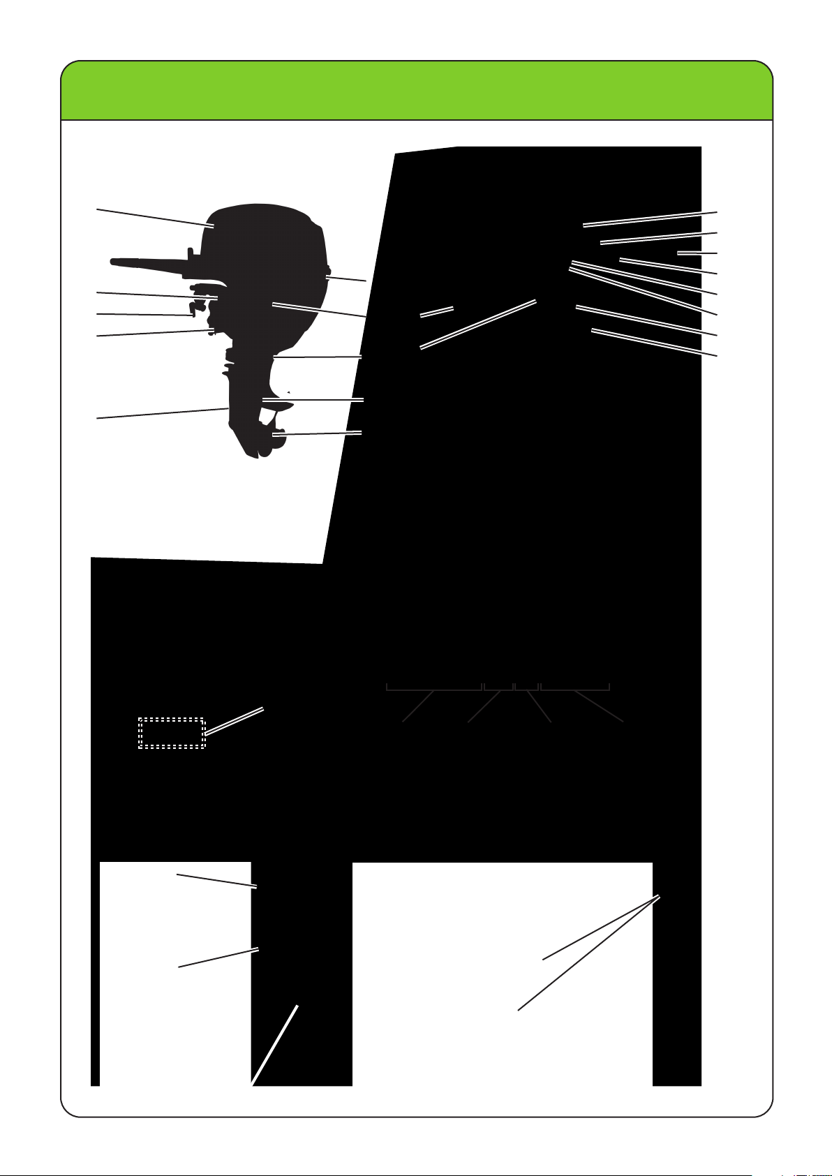
BASIC COMPONENTS
NOTE: All c omponents may not be exactly as shown, also may not be included as standard equipment on
all models.
1
10
6
11
7
12
8
9
2
3
4
5
13
14
15
16
17
18
19
20
1. TOP COWLING
2. SWIVEL BRACKET
3. CLAMP BRACKET
4. TRIM ROD
5. COOLANT WATER I NTAKE
6. TOP COWLING LOCK LEVER
7. LOWER COWLING
8. OIL OUTLET
9. LOWER UNIT HOUSING
10. PROPELLER
SERIAL NUMBER
The outboard motor s erial number is stamped on the label attached t o the
clamp bracket. Record your outboard motor serial number, you will need it
when ordering s pare parts from y our LEHR dealer or f or reference if your
outboard motor is stolen.
11. COOLANT WATER PILOT HOLE
12. TILT LOCK LEVER
13. PULL START HANDLE
14. GEAR S HIFT LEVER
15. TILLER HANDLE
16. ENGINE STOP BUTTON
17. LOW OIL PRESSURE WARNING LIGHT
18. PROPANE CONNECTOR
19. ENGINE RESTRAINT CABLE MOUNT
20. TRANSOM CLAMP HANDLE
LP15S14A1234
MODEL YEAR
EX: 14 = 2014
EX: A = JANUARY
B = FEBRUARY
C = MARCH
SEQUENCE PER MONTH MONTH
INTERNAL
BATTERY
EMISSIONS LABEL
LEHR | ALL RIGHTS RESERVED
WARNING LABELS:
-DETACH FUEL LINE
FROM MOTOR
OR
CLOSE VALVE ON
TANK WHEN NOT IN
USE
-USE ONLY PROPANE
MOTOR FUEL
-FIRE HAZARD
3
Page 6
GENERAL INFORMATION
PROPANE TANK
Use of a LEHR Liquid Draw propane t ank or liquid draw forklift type t ank is recommended. A DOT approved
vapor “BBQ” propane t ank may be used, however extended use at high RPM will result in slowed engine
performance. Connect a vapor type tank t o t he remote propane connector with t he provided high pressure
vapor draw propane hose.
NOTE: Do not use a hose assembly that includes a pressure regulator.
WARNING: If using a liquid draw t ank and liquid draw hose, always t urn off the v alve on tank when done
using. When disconnecting t he t ank, the hose will still contain liquid propane. If the liquid draw
hose needs to be removed, turn off the t ank valve and run the engine to deplete the contents of
the hose before removing t he hose f rom t he t ank.
LEHR LIQUID DRAW
PROPANE TANK
STANDARD 20 lb.
PROPANE TANK
“LIQUID DRAW”
HIGH PRESSURE PROPANE HOSE
“VAPOR DRAW”
HIGH PRESSURE PROPANE HOSE
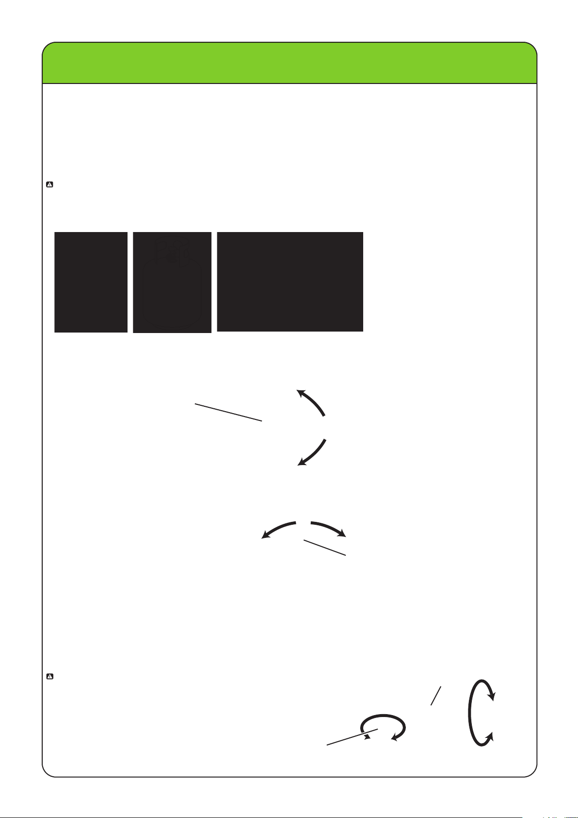
TILLER HANDLE
To change direction wile operating your boat, move t he t iller handle to the left or right as necessary.
TILLER HANDLE
GEAR SHIFT LEVER
Your outboard has three gear shift positions t o provide operation: Forward(F), Neutral(N), and Reverse(R).
Reduce throttle speed to idle speed before shifting. Always shift outboard into gear with a quick motion.
(R)
(N)
(F)
GEAR SHIFT LEVER
THROTTLE GRIP AND THROTTLE FRICTION ADJUSTER
The t hrottle grip is on the t iller handle. Turn t he grip counterclockwise t o increase speed and clockwise t o
decrease speed. A friction device provides adjustable resistance t o movement of the throttle grip or t he
remote control lever, and can be set according t o operator preference. To increase resistance, turn the
adjuster clockwise. To decrease resistance, turn t he adjuster counterclockwise.
WARNING: Do not overtighten the t hrottle f riction adjuster.
If there is t oo much resistance, it could be
difficult to move throttle lever or grip, which
could result in an accident. When constant
speed is desired, tighten t he adjuster just
enough to maintain the desired throttle setting.
4
LEHR | ALL RIGHTS RESERVED
THROTTLE FRICTION
ADJUSTER
THROTTLE GRIP
Page 7
GENERAL INFORMATION
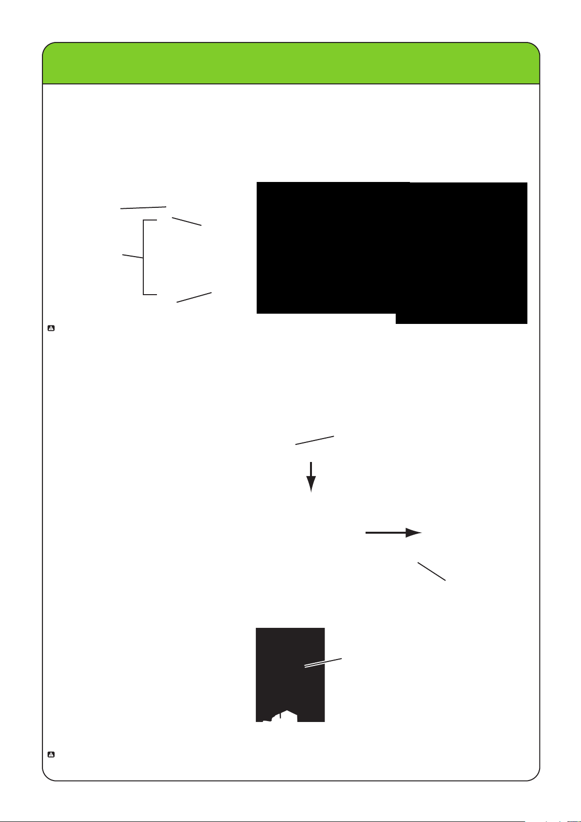
ENGINE STOP SWITCH
The stop switch lock must be attached t o the engine stop switch for t he engine t o run. The hook should be
attached t o a secure place on t he operators clothing, or arm or leg. Should the operator fall over board or
leave the helm, the stop switch lock will pull out the stop switch, stopping ignition t o the engine. This will
prevent the boat from running away under power.
NOTE: The engine cannot be started with t he stop switch lock removed.
ENGINE STOP
SWITCH
STOP SWITCH
LOCK
ENGINE STOP
SWITCH LANYARD
HOOK
CORRECT
WARNING: Attach the engine stop switch hook to a s ecure place on y our clothing, or y our arm or leg
while operating. Do not attach t he hook to clothing that could t ear loose. Do not route t he
lanyard where it could be come entangled, preventing it from f unctioning. Avoid accidentally
pulling the lanyard during normal operation. Loss of engine power means the loss of most
steering control. Also, without engine
people and objects in t he boat to be t hrown f orward.
power, the boat could slow rapidly. This could c ause
INCORRECT
ENGINE STOP BUTTON
To stop t he engine, push and hold the engine stop switch button or pull the lanyard out from t he switch.
ENGINE STOP
BUTTON
MANUAL STARTER HANDLE
To start the engine, first gently pull the handle out until resistance is felt. From that position, then pull the
handle straight out quickly t o crank t he engine.
NOTE: If the shift lever is not in t he neutral
position t he starter rope will be locked
and cannot be pulled
HANDLE
STEERING FRICTION ADJUSTER
A friction device provides adjustable resistance t o t he steering mechanism, and can be set according t o
operator preference. An adjusting screw or bolt is located on t he s wivel bracket.
STEERING FRICTION ADJUSTER BOLT
To increase resistance, turn t he adjuster bolt clockwise. To decrease resistance, turn t he adjuster bolt
counterclockwise.
:
WARNING
steer, which c ould result in an accident.
Do not overtighten the f riction adjuster. If there is t oo much resistance, it could be difficult to
LEHR | ALL RIGHTS RESERVED
5
Page 8
GENERAL INFORMATION
TRIM ROD
The position of the t rim rod determines t he angle of the outboard motor in relation t o the t ransom
TRIM ROD
TRIM ROD
.
TRANSOM CLAMP
TILT LOCK MECHANISM
The t ilt support lock keeps the outboard motor in t he t ilted up position. If the outboard engine needs t o be
tilted up out of the water or to get the propeller higher than t he bottom of the boat, unlock t he t ilt lock
mechanism as shown and t ilt the engine upwards. The tilt lock mechanism will engage and lock the engine
in three possible positions. To lower t he engine, turn the lock lever back t o the lock position. Then lift the
engine slightly to allow lock mechanism to disengage, then c arefully lower the engine all t he way down.
TILT UP AND LOCK
UNLOCK
TILT LOCK LEVER
LOCK
TILT LOCK LEVER
WARNING: Do not use t he t ilt support bar when t railering t he boat. The outboard motor could shake loose
from t he t ilt support and f all. If the motor cannot be trailered in the normal running position, use
an additional support device to secure it in t he t ilt position.
TOP COVER LOCK LEVER
Pull t he lock lever upwards from t he bottom and unhook from t he t op cover. Then lift the c over f rom t he rear
and remove f rom t he f ront hook. When installing t he cover, make sure t he f ront hook is securely inserted in
it’s slot, then lock the rear lever into place. Check t o be sure t he rubber seal f its properly on t he lower cowling.
Then lock the c over by moving the lock lever downward.
RUBBER SEAL
TOP COVER
LOCK
LEVER
LOWER COWLING
FRONT HOOK
LOWER COWLING
LOCK
LEVER
CARRYING HANDLES
Carrying handles are provided on the f ront and rear of the outboard motor. The handles enable you to c arry
the outboard motor with t wo hands.
REAR
CARRYING
HANDLE
6
LEHR | ALL RIGHTS RESERVED
FRONT
CARRYING
HANDLE
Page 9
INSTALLATION
INSTALLATION
Incorrect engine height or obstructions to smooth water flow in front of the propeller can cause propeller
cavitation while the boat is cruising. Cavitation occurs when the engine speeds up momentarily and suddenly
slows as the propeller engages the water. Severe engine damage may result if the motor is operated
continuously while cavitating. During water testing check the buoyancy of the boat, at rest, with its maximum
load. Check that the static water level on the exhaust housing is low eno
power head, when water rises due to waves when the outboard is not running.
MOUNTING THE OUTBOARD MOTOR
• Overpowering a boat could cause severe instability. Do not install an outboard motor with more horsepower
than the maximum rating on the capacity plate of the boat. If the boat does not have a capacity plate,
consult the boat manufacturer.
• This section is inten
possible boat and motor combination. Proper mounting depends in part on experience and the specific boat
and motor combination. Improper mounting of the outboard motor could result in hazardous conditions, or
poor handling, loss of control, or boat damage.
• Your dealer or other person experienced in proper out board motor mountings sho
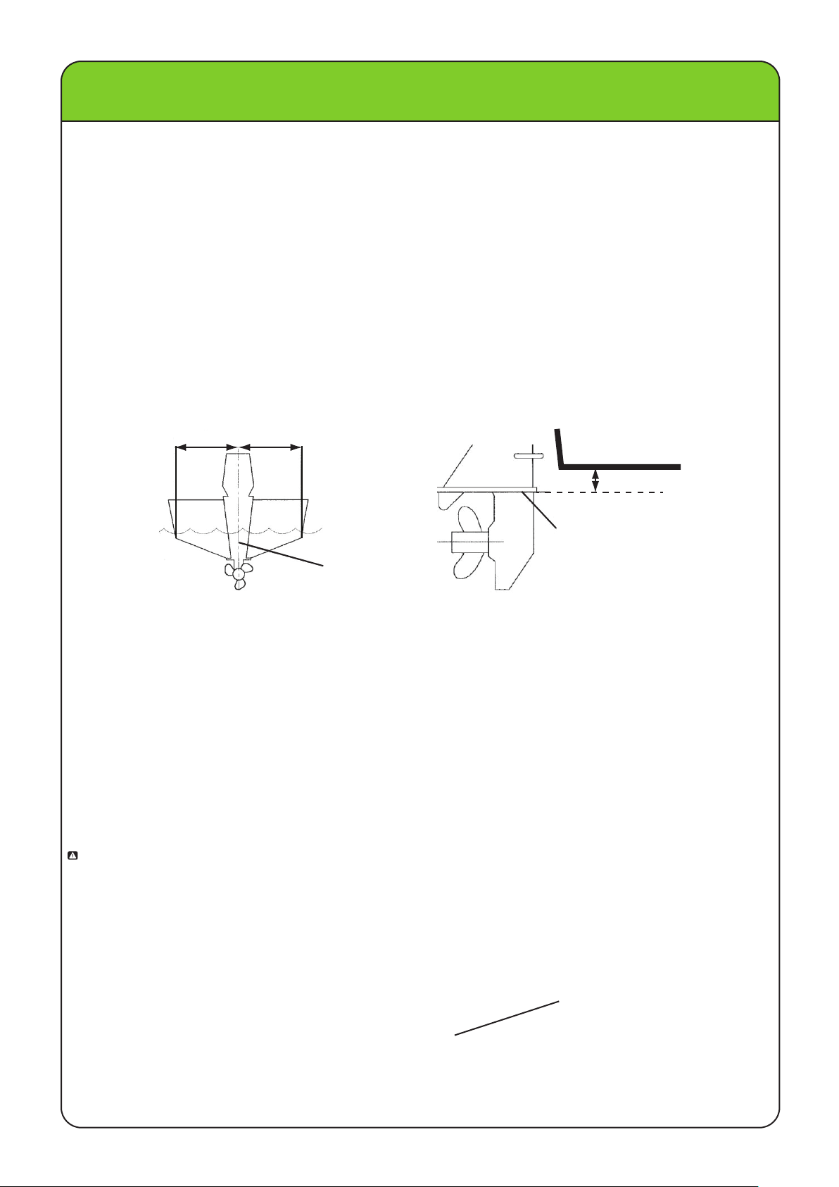
mount your motor. Mount the outboard motor on the center line (keel line) of the boat, and ensure that the
boat itself is well balanced. Otherwise the boat will be hard to steer. For boats without a keel or which are
asymmetrical, consult your dealer.
ded as reference only. It is not possible to provide complete instructions for every
aa
ugh to prevent water entry in to the
uld show you how to
BOTTOM OF HULL
0-1 in (0-25mm)
ANTI-CAVITATION PLATE
CENTER LINE
(KEEL LINE)
MOUNTING HEIGHT
To run your boat at best efficiency, the water resistance (drag) of the boat and outboard motor must be
made as little as possi
If the mounting height is too high, cavitation tends to occur, thus reducing the propulsion, and if the propeller
tips cut the air, the engine speed will rise abnormally and cause the engine to over heat. If the mounting
height is too low, the water resistance will increase and thereby reduce engine efficiency. Mount the
outboard motor so that the anti-cavitation plate is between the bottom of the boat and a level 25mm (1in.)
low it.
be
The optimum mounting height of the outboard motor is affected by the boat and motor combination and the
desired use. Test runs at different heights can help determine the optimum mounting height. Consult your
boat manufacturer for further information on determining the proper mounting height.
CLAMPING THE OUTBOARD MOTOR
1. Place the outboard motor on the transom so that it is positioned as close to the center as possible. Tighten
the transom clamp screws evenly and securely. Occasionally check the clamp screws for tightness during
operation of the outboard motor because they could become loose due to engine vibration.
WARNING: Loose clamp screws could allow the outboard motor to fall off or move on the transom. This could
cause loss of control and seri
Occasionally check the screws for tightness during operation.
2. If an engine restraint cable or chain attachment is equipped on your boat, the cable or chain should be
used. Attach one end of the engine restraint cable attachment to the engine clamp and the other to a
secure mounting point on the boat. Otherwise the engine could be completely lost if it accidentally falls
off the transom.
ble. The mounting height of the outboard motor greatly affects the water resistance.
ous injury. Make sure the transom screws are tightened securely.
ATTACH ONE END OF THE RESTRAINT
CABLE THROUGH THIS CLAMP MOUNT
AND ONE END SECURELY ON THE BOAT
LEHR | ALL RIGHTS RESERVED
7
Page 10

OPERATION
PRE-OPERATION CHECKS
WARNING: If anything in the pre-operation check is not working properly, have it inspected and repaired
before operating t he outboard motor. Failure to do so could result in an accident.
CONTROLS
• Check throttle, shift, and steering f or proper operation before starting t he engine.
• T he controls should work smoothly, without binding or unusual free play.
• Look for loose or damaged connections.
• Check operation of the starter and stop switches when t he outboard motor is in t he water.
• If the engine has not been used in some t ime, rev it in neutral to be sure it returns t o idle before putting it
in gear.
ENGINE
• Check the engine and engine mounting.
• Look for loose or damaged f asteners.
• Check the propeller for damage.
CHECKING THE ENGINE OIL LEVEL
1. Put the outboard motor in an upright position (not tilted).
2. Insert the oil dipstick all t he way in. Pull it out and check the oil
the level f alls between t he upper and lower marks. Fill with oil if it is below the lower mark, or drain t o
the specified level if it is above t he upper mark.
UPPER LEVEL MARK
level using the oil dipstick to be sure
LOWER LEVEL MARK
Recommended engine oil:
Use a quality 4-stroke motor oil.
Engine oil type:
10W-30
Engine oil quantity:
1.06 US qt (1.0L)
WARNING: ALL ENGINES ARE SHIPPED FROM T HE FACTORY WITHOUT ENGINE OIL.
ADD OIL BEFORE STARTING ENGINE.
FUEL
• Use a LEHR Liquid Draw propane t ank or any DOT approved propane t ank.
• Check to be sure you have plenty of fuel f or your trip.
• Make sure t here are no f uel leaks or propane f umes.
REFUELING INSTRUCTIONS
WARNING: PROPANE AND ITS VAPORS ARE HIGHLY FLAMMABLE AND EXPLOSIVE!
• Stop engine before refueling.
• Do not smoke when refueling, and keep away f rom sparks, flames, or other sources of ignition.
• Refuel in a well-ven
• Refuel portable f uel t anks off the boat.
• Have your propane tanks refilled or exchanged at a certified propane refueling or exchange center.
tilated area.
USE THE CORRECT PROPANE TANK
NOTE: Use of a LEHR Liquid Draw tank is recommended. Forklift tanks are also liquid draw and may be
used. These tanks may be operated vertically or laid down horizontally. If used horizontal, the tank
must be positioned correctly t o ensure liquid is withdrawn. Use of a f orklift style mounting bracket is
recommended.
A standard U.S. 20 lb. DOT approved propane t ank may be used, however extended use at high R.P.M. may
result in slowed engine performance.
8
LEHR | ALL RIGHTS RESERVED
Page 11

OPERATION
CONNECTING THE PROPANE TANK
1. Make sure the engine is off and t he propane tank valve is closed.
2. Unscrew the connector plug from the propane connector on the engine, then connect the high pressure propane hose
to the propane connector by turning the connector on the hose clockwise.
3. When using a liquid draw t ank, connect the “liquid draw” propane hose t o tank (right hand threads).
When using a vapor draw or BBQ type tank, connect the “vapor draw” propane hose t o t he propane tank
(left hand t hreads).
NOTE: The t hreads on the high pressure propane hose that connect to the t ank are left hand t urn.
“LIQUID DRAW”
HIGH PRESSURE
PROPANE HOSE
LIQUID DRAW TANK CONNECTION (FORKLIFT TYPE)
PROPANE
CONNECTOR
CONNECTOR
PLUG
HIGH PRESSURE
PROPANE HOSE
VALVE
LEHR LIQUID DRAW
PROPANE TANK
VAPOR DRAW TANK CONNECTION (BBQ TYPE TANK)
“VAPOR DRAW”
HIGH PRESSURE
PROPANE HOSE
LEFT HAND
TURN THREADS
3. Open t he valve on t he t ank slowly. Opening the v alve t oo quickly could cause a sudden s urge of
propane to activate a safety f low limiting device within t he t ank.
NOTE: Use only a high pressure propane hose. Do not use a hose with a regulator attached.
NOTE: When a new hose f rom a propane t ank is being used, it may take a few seconds f or t he propane flow
to reach t he engine. The engine may start and t hen die, or not start immediately. Extra pulls of the
starter are usually necessary for t he f low
start guide f or priming the propane system.
to reach t he engine, or follow t he procedure in t he quick
VALVE
LEHR VAPOR DRAW
PROPANE TANK
LEHR | ALL RIGHTS RESERVED
9
Page 12

OPERATION
STARTING THE ENGINE
1. Place t he gear shift lever in neutral. The engine is equipped with a lockout which will prevent the starter
rope from being pulled if the engine is engaged in f orward or reverse. If your engine is electric start, it
will not start if it is engaged in forward or reverse.
WARNING: Keep hands, hair, and c lothing away from rotating parts while the engine is running. Do not
touch or remove electrical parts when starting or during operation.
2. Attach t he stop switch lanyard to a secure place on your clothing, or your arm or leg. Then install t he stop
switch lock on t he other end of the lanyard into t he engine stop switch.
• Do not attach t he lanyard t o clothing that could tear loose. Do not route the lanyard where it could become
entangled, preventing it from f unctioning.
• A void accidentally pulling the lanyard during normal operation. Loss of engine power means the
most steering c ontrol. Also, without engine power, the boat could slow rapidly. This could cause people
and objects in the boat to be t hrown f orward.
STOP SWITCH LANYARD
STOP SWITCH LOCK
ENGINE STOP SWITCH
GEAR SHIFT LEVER
(N) NEUTRAL POSITION
loss of
3.
Place
the
a t urn f aster than t he “start” or I dle position.
throttle
4. Pull t he manual starter handle slowly until you f eel resistance. Then give a strong pull straight out to
start the engine. Repeat if necessary.
5. After t he engine starts, slowly return t he manual starter handle to the original position before releasing it.
6. Slowly return t he t hrottle grip to t he f ully closed position.
NOTE: If the engine fails t o start after 4 or 5 tries, open the t hrottle a small amount more (between 1/4 - 1/3
throttle) and try again. Also if the engine is warm and f ails t o star
and try t o start the engine again. If the weather is below 45 degrees F, open the t hrottle t o 1/4 - 1/2
to start cold.
grip
in
the
"START" position
.
If the engine is cold, set the position about 1/8 to 1/4 of
START POSITION
1/8 TO 1/4 THROTTLE
t, open t he t hrottle a small amount
ELECTRIC START MODELS
Place t he gear shift lever in neutral. The engine is equipped with a neutral safety switch, which will prevent
the starter to engage if the engine is in gear. Place t he t hrottle in the start position. Insert the key and t urn
it clockwise and release after t he engine is running.
10
.
LEHR | ALL RIGHTS RESERVED
Page 13

OPERATION
WARMING UP ENGINE
1. Warm up the engine by operating at 1/2 t hrottle or less for t he f irst 4 minutes. Failure to do so may cause
the engine to stall in cold weather, and will shorten engine life.
2. Check f or a steady f low of water f rom t he cooling water pilot hole.
NOTE: A continuous flow of water from t he cooling water pilot hole shows that the water pump is pumping
water t hrough t he cooling passages. If water is not flowing out of the hole at all t imes while the
engine is running, over heating and serious damage could occur. Stop t he engine and check whether
the cooling water inlet on t he lower case or t he cooling water pilot hole is blocked. Consult your
dealer if the problem cannot be located and corrected.
COOLING WATER
PILOT HOLE
SHIFTING
WARNING: Before shifting, make sure no swimmers are in the water near your boat.
1. Place t he t hrottle in the slowest position.
2. Move t he gear shift lever quickl
WARNING: When operating your outboard engine in reverse, go slowly. Do not attempt to open t he t hrottle
more than half throttle in reverse. Otherwise your boat can become unstable which can result
in loss of control or a possible accident.
y to t he desired gear f rom neutral t o f orward or reverse.
STOPPING ENGINE
1. Push and hold t he engine stop button until the engine completely stops.
2. After t he engine has stopped disconnect or close the valve on the propane tank.
ADJUSTING BOAT TRIM
WARNING: Stop the engine before adjusting the t rim angle. Use care t o avoid being pinched when removing
the t rim rod. Use caution when t rying a trim position f or t he f irst time. Increase speed gradually
and watch for any signs of instability or control problems. Improper t rim angle can c ause loss of
control.
• T ilt the engine up slightly.
• Reposition t he rod inside t he desired hole.
• T o raise t he bow (”trim-out”), move t he t rim rod away f rom t he t ransom.
• T o lower t he
• T est the boat with t he t rim set to different angles to find the position t hat works best for your boat and
operating c onditions.
bow (”trim-in”), move the t rim rod closer to the t ransom.
TRIM ROD
NOTE: The outboard motor t rim angle can be changed approximately 4 degrees by shifting the t rim rod one
hole.
LEHR | ALL RIGHTS RESERVED
11
Page 14

OPERATION
When t he boat is on plane, a bow-up attitude results in less drag, greater stability and efficiency. This is
generally when t he k eel line of the boat is up about 3 t o 5 degrees. With t he bow up, the bow of the boat may
have a greater t endency t o steer to one side or t he other. Compensate f or t his as you steer. The t rim t ab
can also be adjusted to help to help offset this effect. When the bow is down, it is easier t o accelerate f rom
a standing start onto plane.
WATER LINE
BOW UP
Too much trim-out puts t he bow of the boat too high in the water. Performance and economy are decreased
because the hull of the boat is pushing t he water and t here is more drag. Excessive trim-out can also c ause
the propeller to ventilate, which reduces performance further, and t he boat may “porpoise” (hop in the water)
which could t hrow
BOW DOWN
Too much trim-in causes the boat to “plow” through t he water, decreasing f uel economy and making it hard
to increase speed. Operating with excessive t rim-in at higher s peeds also makes t he boat unstable.
Resistance at the bow is greatly increased, heightening the danger of “bow steering” and making operation
difficult and dangerous.
the operator and passengers overboard.
WATER LINE
WATER LINE
NOTE: Depending on the t ype of boat, the outboard motor t rim angle may have little effect on t he t rim of the
boat when operating.
TILTING UP AND DOWN
If the engine will be stopped f or some time and the boat is moored in shallows, the outboard motor should
be tilted up t o protect the propeller and casing f rom damage f rom collision with obstructions, and also to
reduce salt corrosion.
WARNING: Before tilting the outboard motor, follow the procedure under “Stopping Engine” in this section.
Never
result. Do not tilt the engine by pushing the tiller handle alone because this could break the
handle. Hold f rom t he rear of the top cover t o help t ilt the engine up and down. Keep the power
unit higher than the propeller at all times otherwise water could run into the c ylinder and cause
damage. The outboard motor cannot be tilted while in reverse.
tilt the outboard motor while the engine is running. Sever damage from overheating can
PULL FROM HERE
WARNING: Be sure all people are clear of the outboard motor when t ilting up and down, also be careful not
to pinch any body parts between t he drive unit and engine bracket.
Follow t he procedures in “Tilt Lock Mechanism” on pg 6 for t ilting the engine
12
LEHR | ALL RIGHTS RESERVED
up and down instructions.
Page 15

MAINTENANCE
TRANSPORTING AND STORING THE OUTBOARD MOTOR
WARNING: Leaking f uel is a fire hazard. When t ransporting or storing t he outboard motor, disconnect the
propane connector t o prevent the possibility of fuel f rom leaking. Use c are when transporting
the f uel t ank whether in boat or car.
Never get under the lower unit while it is tilted, even if a motor support bar is used. Severe injury could occur
if the outboard motor accidentally falls.
Do not use the tilt support lever when trailering the boat. The outboard motor could shake loose from the tilt
support and fall. If the motor can not be trailered in the normal running position, use an additional support
device to secure it in the tilt position.
The outboard motor should be trailered and stored in the normal running position. If there is insufficient road
clearance in this position, then trailer the outboard motor in the tilt position using a motor support device such
as a transom saver bar.
When transporting or storing the outboard motor while removed from a boat, keep the outboard motor in the
attitudes shown.
WARNING: This engine weighs at least 88.7 lbs. (40 Kg). Use a hoist or an extra person to help when ever
possible when lifting and moving the engine.
STORE IN THE UPRIGHT POSITION
CARRY FROM THE HANDLES
STORE WITH THE TILLER SIDE DOWN
CUSHION
FLOOR
FLOOR
STORING THE OUTBOARD MOTOR
NOTE: Place a t owel or something similar under t he outboard motor to protect it from damage.
When storing y our outboard motor f or prolonged periods of time (2 months or longer), several impor
procedures must be performed t o prevent excessive damage.
NOTE: Cooling system flushing is essential to prevent the cooling system from clogging up with salt sand,
or dirt. In addition, fogging / lubricating of the engine is mandatory to prevent excessive engine
damage due to rust. Perform the flushing and fogging at the same time.
tant
• To prevent problems which can be caused by oil entering the cylinder from the sump, keep the outboard
motor in the attitude shown when transporting and storing it. If storing or transporting the outboard motor
on its side (not uprig
• Do not place the outboard motor on its side before the cooling water has drained from it completely,
otherwise water may enter the cylinder through the exhaust port and cause engine trouble.
• S tore the outboard motor in a dry, well ventilated place, not in direct sunlight.
ht), put it on a cushion after draining the engine oil.
LEHR | ALL RIGHTS RESERVED
13
Page 16

MAINTENANCE
PROCEDURE FOR FLUSHING AFTER SEA WATER USE
If the engine has been operated in saltwater, it should always be flushed with fresh water after each use before being
stored. Do
damaged
water t o the cooling water passages.
1. A flushing port has been provided f or ease of flushing. Unscrew the f resh water garden hose adapter
from its mount and attach a garden hose t o it. Turn on t he water t o t he hose and adjust the flow s o t hat
the stream f rom t he c ooling water pilot hole is approximately the s ame as if the engine is running in t he
water.
2. Run the engine at a fast idle for a few minutes in neutral position.
3. Wash the outboard motor body using fresh water.
4. Turn off the motor.
5. Turn off the garden hose and reattach it to its mount.
6. Wipe t he water off the motor, cleaning the body thoroughly.
7. Let the cooling water drain completely out of the motor.
not
run
the
or
the engine will be damaged from overheating. Before starting the engine, be sure t o supply
FRESH WATER
GARDEN HOSE
ADAPTER
engine
without
supplying
it
with
cooling
water.
Either
the
engine
water
MOUNT
pump
will
be
WARNING: Never engage forward gear if engine is running when not attached t o a boat. An exposed,
spinning propeller is dangerous. Even in a t ank, on a stand or mounted on a boat, the engine
can suddenly move when shifted into gear causing the t ank or motor t o shift and expose the
propeller which c ould result in serious injury.
NOTE: Do not touch or remove electrical parts when starting or during operation. Keep hands, hair, and
clothes away from the flywheel and other rotating parts while the engine is running.
14
LEHR | ALL RIGHTS RESERVED
Page 17

MAINTENANCE
LUBRICATION
1. Remove t he spark plug and spray some f ogging oil into t he cylinders if the engine will not be operated
for several months.
2. Grease the spark plug threads and install the spark plug and torque to proper specification.
3. Change the gear oil. Inspect the oil for the presence of water that indicates a leaky seal.
4. Grease all grease fittings.
CLEANING THE OUTBOARD MOTOR AFTER USE
1. After use wash the exterior of the outboard motor with fresh water.
2. Flush the cooling system with fresh water.
CHECKING PAINTED SURFACE OF MOTOR
1. Check the motor for scratches, nicks, or flaking paint. Areas with damaged paint are more likely to
corrode. If necessary, clean and paint the areas.
NOTE: Be sure to turn off the engine when you perform maintenance unless otherwise specified. If you or
the owner are not familiar with machine servicing, this work should be done by your LEHR dealer
or other qualified mechanic.
REPLACEMENT PARTS
If replacement parts are necessary, use only genuine LEHR parts or parts of the same type and of
equivalent strength and materials. Any part of inferior quality may malfunction, and the resulting loss of
control coul
from your LEHR dealer, or directly from LEHR.
d endanger the operator and passengers. LEHR genuine parts and accessories are available
MAINTENANCE CHART
Frequency of maintenance operations may be adjusted according to the operating conditions, but the
following table gives general guidelines. Refer to the sections in this chapter for explanations of each
owner-specificaction. When operating in salt water or dirty water, the engine should be flushed with clean
water after each use.
The “ ” symbol indicates the check-ups which you may carry out yourself.
•
The “ ” symbol indicates work to be carried out by your LEHR dealer.
Initial Every
Item Actions
Anodes(s)
Cooling water passages
Cover clamps Inspection
Fuel system Inspection
Gear oil Change
Greasing points
Idling speed Inspection /adjustment
Propeller and cotter pin Inspection/replacement
Shift link Inspection/adjustment
Thermostat Inspection/replacement
Throttle link/throttle
cable/ throttle
Water pump Cleaning/adjustment/replacement
Engine oil Inspection/change
Spark plug(s) Ins
Valve clearance Inspection/adjustment
Inspection/replacement
Cleaning
Greasing
Inspection/adjustment
pection/adjustment/replacement
10 hours 50 hours 100 hours 200 hours
(1
month)
(3
months)
( 6 months)
(
1
year)
LEHR | ALL RIGHTS RESERVED
15
Page 18

MAINTENANCE
GREASING
NOTE: Use only water resistant grease.
Grease in these areas:
SPARK PLUGS
WARNING: When removing or installing a spark plug, be careful not to damage the insulator. A damaged
insulator could allow external sparks, which could lead to explosion or fire.
The spark plug is an important engine part and is easy to inspect. The condition of the spark plug can
indicate the condition of the engine. Normally, the spark plug in a propane engine will stay very clean.
Oily or dark c olor ceramic could indicate a malfunction. Do not attempt to diagnose any problems yourself.
Instead, take the outboard motor to a LEHR dealer. You should periodically remove and inspect the spark
plug because the electric arcing will cause the spark plug to slowly erode and t he gap will increase.
If electrode erosion becomes excessive, or if carbon and other deposits are excessive, you should replace
the spark plug with an
Before fitting the spark plug, measure the electrode gap with a wire thickness gauge. Adjust the gap to
specification if necessary.
When fitting the plug, always clean the gasket surface and use a new gasket. Wipe off any dirt from the
threads and screw in the spark plu
other of the correct type.
Spark plug Boots
g to the correct torque.
Spark plug ID mark (i.e. NGK)
Standard spark plug: DPR6EA-9
Spark plug gap:
0.020-0.024 in (0.5-0.6 mm)
Spark plug torque:
13.3 ft-lb (18.0 Nm)
NOTE: If a torque-wrench is not available when you are fitting a spark plug, a good estimate of the correct
torque is 1/4 to 1/2 a turn past finger tight. Have the spark plug adjusted to the correct torque as
soon as possible with a torque wrench.
INSPECTION CHECKPOINTS
Periodically check t he f uel system for leaks. With the propane t ank attached, and the engine cover removed,
inspect the following f uel s ystem parts f or leakage. Leaks can be identified by smell of propane or carefully
listening for a hissing sound of escaping gas. Suspected leaks can be verified by applying soapy water
solution on t he area and observing bubbles forming.
16
LEHR | ALL RIGHTS RESERVED
Page 19

MAINTENANCE
NOTE: Inspect the f ollowing f or any source of a fuel leak. A propane sniffing device may be used to inspect.
• F uel system parts leakage
• F uel line joint leakage
• F uel line cracks or other damage
• F uel connector leakage
ADJUSTING IDLING SPEED
WARNING: Do not touch or remove electrical parts when starting or during operation. Keep hands, hair, and
clothes away from t he f lywheel and other rotating parts while t he engine is running.
CAUTION: This procedure must be performed while t he outboard motor is in the water. A flushing attachment
or test tank can be used.
NOTE: A diagnostic t achometer should be used f or t his procedure. Results may vary depending on whether
testing is conducted with t he f lushing attachment, in a t est tank, or with t he outboard motor in t he
water.
1. Start the engine and allow it to warm up fully in neutral until it is running smoothly.
NOTE: Correct idling speed inspection is only possible if the engine is f ully warmed up. If not warmed up
fully, the idle speed will measure higher t han normal. If you have difficulty verifying t he idle speed,
or the idle speed requires adjustment, consult a LEHR dealer or other qualified mechanic.
2. Verify whe
idle speed screw with a phillips head screw driver.
ther t he idle speed is set to specification (1050 + 150 RPM). Adjust the speed by turning t he
IDLE SPEED SCREW CARBURETOR
CHANGING ENGINE OIL
WARNING: Avoid draining t he engine oil immediately after stopping the engine. The oil is hot and should
be handled with care t o avoid burns.
• B e sure t he outboard motor is securely fastened to t he t ransom or a stable stand.
• Do not overfill t he oil, and be sure the outboard motor is upright (not tilted) when checking and changing
the engine oil.
• If the oil level is above t he upper level mark, drain until the level meets the specified capacity. Overfilling
the oil could cause leakage or damage.
• Change the engine oil after the f irst 10 hours of operation, and every 100 hours or at 6 month intervals
thereafter. Otherwise t he engine will wear quickly.
NOTE: Change t he engine oil when the oil is still warm.
OIL DRAIN PLUG
OIL FILL CAP
(REAR VIEW OF ENGINE)
1. Put the outboard motor
2. Remove t he oil fill cap.
3. Prepare a suitable container that holds a larger amount than t he engine oil c apacity. Loosen and remove
the drain plug while holding t he container under t he drain hole. The oil drain plug is located on t he
tiller s ide of the engine. Use a 14 mm socket wrench. Then remove the oil f ill cap. Let the oil drain
completely. Wipe up any s pilled oil immediately.
4. Put a new gasket on the oil drain plug. Apply a light coat of oil t o the gasket and install the drain screw.
in an upright position (not tilted).
TORQUE TO 13.3 ft-lb (18 N-m)
NOTE: If a torque wrench is not available when you are installing the drain screw, finger t ighten the screw
just until the gasket comes in contact with the surface of the drain hole. Then t ighten 1/4 to 1/2 t urn
more. Tighten t he drain screw t o the c orrect torque with a t orque wrench as s oon as possible.
5. Add t he correct amount of oil t hrough t he f iller hole. Install t he oil fill cap
.
LEHR | ALL RIGHTS RESERVED
17
Page 20

MAINTENANCE
5. Make sure that there are no oil leaks. Continued operation with an oil leak could cause severe engine
damage.
6. Turn off the engine and wait 3 minutes. Recheck t he oil level using t he oil dipstick to be sure t he level
falls between t he upper and lower marks when t he dipstick is inserted in all t he way. Add oil if the level
is below t he lower mark, or drain t o t he s pecified level if it is above the upper mark (see pg. 8).
7. Dispose of used oil according to local regul
ations.
NOTE: Change the oil more often when operating the engine under adverse conditions such as extended
trolling.
Recommended engine oil: 10W - 30
4-stroke outboard motor oil
Engine oil quantity:
1.0L (1.06
US
qt)
CARBURETOR
OIL DIPSTICK HANDLE
CHECKING WIRING AND CONNECTORS
• Check that each grounding wire is properly secured.
• Check that each connector is engaged and secured.
EXHAUST LEAKAGE
Start the engine and check that no exhaust leaks from the joints between the exhaust cover, cylinder
head, and cylinder.
WATER LEAKAGE
Start the engine and check that no water leaks from the joints between the exhaust cover, cylinder head,
cylinder, thermostat housing, and t hermostat ho
se.
CHECKING PROPELLER
WARNING: You could be seriously injured if the engine accidentally starts when you are near the propeller.
Before inspecting, removing, or installing the propeller, remove the spark plug cap from the
spark plug. Also, place the shift control in neutral, and remove the lanyard from the engine stop
switch.
•
Check each of the propeller blades for wear, erosion from cavitation, or other damage.
• Check the propeller shaft for damage.
• Check the splines for wear or damage.
• Check for fish line tangled around the propeller shaft.
• Check the propeller shaft oil sea
l for damage.
REMOVING THE PROPELLER
1. Straighten the cotter pin and pull it out using a pair of pl iers.
2. Remove the propeller nut and washer.
3. Remove the propeller and thrust washer.
1
2
3
4
1. COTTER PIN
2. PROPELLER NUT
3. WASHER
4. PROPELLER
5. THRUST WASHER
6
5
6. PROPELLER SHAFT AND SPLINES
18
LEHR | ALL RIGHTS RESERVED
Page 21

MAINTENANCE
WARNING: Do not use your hand t o hold t he propeller when loosening or t ightening t he propeller nut. Put
a wood block between t he anti-cavitation plate and the propeller to prevent the propeller f rom
turning.
ANTI-CAVITATION PLATE
WOOD BLOCK
PUT A WOOD BLOCK BETWEEN THE PROPELLER AND
THE ANTI-CAVITATION PLATE TO KEEP IT FROM TURNING
INSTALLING THE PROPELLER
• Be sure to install the thrust washer before installing the propeller, otherwise t he lower case and propeller
boss could be damaged.
• Be sure to use a new cotter pin and bend the ends over securely. Otherwise the propeller could come
off during operation and be lost.
1. Apply corrosion resistant grease to the propeller shaft.
2. Install the thrust washer, and propeller on the propeller shaft.
3. Install the washer. Tighten the propeller nut until there is no forward-and-backward movement.
4. Align the propeller nut with the propeller shaft hole. Insert a new cotter pin in the hole and bend the
cotter pin ends.
NOTE: If the propeller nut does not align with the propeller shaft hole after tightening it, loosen the
nut until it aligns with the hole.
COTTER PIN
PROPELLER SELECTION
Your LEHR outboard engine is supplied with a propeller t hat matches the needs of a boat most suited t o an
engine of its size. If you feel you are not getting optimal performance f rom t he engine on y our boat, a
different pitch propeller could help. The performance of your outboard motor will be affected if you c hoose a
different propeller, as an incorrect choice could adversely affect performance and c ould also s eriously damage
the motor. Engine speed depends on t he propeller size and boat load. If engine speed is t oo high or t oo low
for good engine performance, this will have an adverse effect on the engine. For a greater operating load, a
smaller-pitch propeller is more suitable as it enables the correc
a larger-pitch propeller is more suitable f or a smaller operation load.
t engine speed to be maintained. Conversely,
PROPELLER MARK
X
1 2 3
1. PROPELLER DIAMETER IN INCHES.
2. PROPELLER PITCH IN INCHES.
3. TYPE OF PROPELLER (PROPELLER MARK).
NOTE: Select a propeller which will allow the engine to reach the middle or upper half of the operation range
at full t hrottle with the maximum boat load. In operation conditions such as light boat loads, do not
allow the engine RPM t o rise above the maximum recommended range, reduce the t hrottle s etting to
maintain t he engine in t he proper operation range.
LEHR | ALL RIGHTS RESERVED
19
Page 22

MAINTENANCE
CHANGING GEAR OIL
• Be sure the outboard motor is securely fastened to the transom or a stable stand. You could be severely
injured if the outboard motor falls on you.
• Never get under the lower unit while it is tilted, even when the tilt support lever or knob is locked.
Severe injury could occur if the outboard motor accidentally falls.
1. Tilt the outboard motor so that the gear oil drain screw is at the lowest point possible.
2. Place a suitable container unde
3. Remove the gear oil drain screw.
Recommended
Hypoid
Gear
oil
0.26 US US qt
NOTE: If a magnetic gear oil drain screw is equipped, remove all metal particles from the screw before
installing it.
• Always use new gaskets.
• Do not reuse the removed gaskets.
4. Remove the oil Ievel plug to allow the oil to drain completely. Inspect the used oil after it has been
drained. If the oil is milky, water is getting into the gear case which can cause gear and bearing damage.
Consult your LEHR dealer for repair of the lower unit seals.
5. With the outboard motor in a vertical position and using a flexible or pressurized filling de
gear oil into the gear oil drain screw hole.
6. When the oil begins to flow out of the oil level plug hole, insert and tighten the oil level plug.
7. Insert and tighten the gear oil drain screw.
gear
quantity
gear
oil
:
. (0
oil:
SAE#90
.250
L)
r the gear case.
OIL LEVEL PLUG
GEAR OIL DRAIN SCREW
vice, inject the
INSPECTING AND REPLACING ANODES
LEHR outboard motors are protected from corrosion by sacrificial anodes. Inspect the anodes periodically.
Remove scales from the surfaces of the external anode. Do not paint the external anode, as this would
render it ineffective.
EXTERNAL
ANODE
INTERNAL
ANODE
OIL DIPSTICK
COATING THE BOAT BOTTOM
A clean hull improves boat performance. The boat bottom should be kept as clean of marine growth as
possible. If necessary, the boat bottom can be coated with an anti-fouling paint approved for your area
to inhibit marine growth. Do not use anti-fouling paint which includes copper or graphite. These paints
can cause more rapid engine corrosion.
20
LEHR | ALL RIGHTS RESERVED
Page 23

TROUBLESHOOTING
A problem in the f uel, compression, or ignition systems can cause poor starting, loss of power, or other
problems. This section describes basic checks and possible remedies. Whenever difficulties are encountered
please call LEHR customer s ervice f or help. 1-866-941-LEHR (5347)
ENGINE WILL NOT START OR OPERATE
Q: Is engine stop switch lanyard not attached?
A: Attach lanyard.
Q: Is t hrottle speed set incorrectly?
A: Set throttle s peed t o 1/8 - 1/4 or less, unless t he weather is cold, then set to 1/4 - 1/2 t hrottle. See pg 10.
Q: Is s hift lever in gear?
A: Shift to neutral.
Q: Is propane tank empty, and fully connected?
A: Shake the t ank to feel f or liquid, then be sure it is fully connected and t he valve is opened correctly (slowly).
Q: Is t he spark plug f ouled or incorrect type?
A: Inspect spark plugs. Clean or replace with recommended type.
Q: Is s park plug cap f itted incorrectly?
A: Check and re-fit caps.
Q: Is ignition wiring damaged or poorly connected?
A: Check wires for wear or breaks. Tighten all loose connections. Replace worn or broken wires.
Q: Possible f aulty ignition parts?
A: Have serviced by LEHR dealer.
Q: Possible f aulty internal engine parts?
A: Have serviced by a LEHR dealer.
ENGINE IDLES IRREGULARLY OR STALLS
Q: Is propane tank empty?
A: Check t ank f luid level by shaking it.
Q: Is s park plug fouled or incorrect type or gap?
A: Inspect spark plug. Clean gap, adjust to c orrect gap or replace with recommended t ype.
Q: Is t he I dle speed set correctly?
A: Adjust Idle screw or have serviced by LEHR dealer.
Q: Are fuel joints connected correctly?
A: Check f or any leaks or smell of propane. Tighten any loose f ittings. Replace any f aulty f uel lines or
connectors.
Q: Is t hermostat faulty or clogged?
A: Have serviced by LEHR dealer.
Q: Is c arburetor faulty?
A: Have serviced by LEHR dealer.
Q: Is engine oil level low?
A: Check oil level and add oil if needed.
ENGINE POWER LOSS
Q: Is f uel s upply running low?
A: Shake propane t ank
settings until fuel s upply is replenished.
to determine if propane level is low. If so, replace tank or operate at reduced t hrottle
Q: Is t he engine running hot?
A: Check f or debris around t he water pump inlet in t he lower unit, remove obstructions.
Q: Is f uel s ystem obstructed?
A: Check f or pinched or kinked f uel line or other obstructions in f uel line.
Q: Is propeller damaged?
A: Have propeller repaired or replaced.
LEHR | ALL RIGHTS RESERVED
21
Page 24

TROUBLESHOOTING
Q: Is propeller pitch or diameter incorrect?
A: Install correct propeller t o operate outboard at its recommended speed.
Q: Is trim angle correct?
A: Adjust trim angle t o achieve most efficient operation.
Q: Is motor mounted at incorrect height on t ransom?
A: Have motor adjusted t o proper t ransom height.
Q: Is boat bottom f ouled with marine growth?
A: Clean bottom of boat.
Q: Are weeds or other f oreign matter t angled on gear housing?
A: Remover f oreign matter and clean power unit.
Q: Is spark plug gap incorrect?
A: Inspect and adjust as specified.
Q: Is ignition wire damaged or poorly connected?
A: Check wires for wears and breaks.
Q: Have electrical wires failed?
A: Have serviced by a LEHR dealer.
Q: Is propeller damaged?
A: Have propeller repaired or replaced.
Q: Is propeller shaft damaged?
A: Have serviced by a LEHR dealer.
IMPACT DAMAGE
WARNING: The outboard motor c an be seriously damaged by a collision while operating or traveling.
Damage may make the outboard motor unsafe t o opera
If the outboard motor hits an object in t he water, follow t he procedure below.
1. Stop t he engine immediately.
2. Inspect the control system and all components for damage. Also inspect boat for damage.
3. Whether damage is found or not, return to the nearest harbor slowly and carefully.
4. Have t he outboard motor inspected before operating it again.
te.
STARTER WILL NOT OPERATE
If the start mechanism does not operate (the engine cannot be c ranked with t he starter), the engine can be
started with an emergency starter rope.
WARNING: Use this procedure only in an emergency and only t o return t o the port for repairs.
• Make sure t he gear s hift lever is in neutral. Otherwise t he boat could unexpectedly start to
move, which c ould result in an accident.
• Attach t he engine stop switch lanyard t o a secure place on your clothing, or your arm or leg while operating.
• Do not attach t he lanyard t o clo
entangled, preventing it from f unctioning.
thing t hat could tear loose. Do not route t he cord where it could become.
• A void accidentally pulling the lanyard during normal operation. Loss of engine power means the loss of
most steering control. Also without engine power, the boat could slow rapidly. This c ould cause people
and objects in t he boat to be t hrown f orward.
• B e sure no one is standing behind you when pulling t he starter rope. It could whip behind you and hurt
someone.
• A n exposed, rotating flywheel is very dangerous. Keep loose clothing and other objects away when
starting t he engine. Do not touch t he f lywheel or other moving or parts when t he engine is running.
22
LEHR | ALL RIGHTS RESERVED
Page 25

TROUBLESHOOTING
EMERGENCY ENGINE START
NOTE: A tool k it is supplied with each engine. The tool k it contains the emergency starter rope, handle and
tools necessary to start the engine if the manual pull or electric starter fail. Keep t his tool k it on
your boat at all t imes in case of an emergency.
1. Remove the top engine cowling.
2. Remove the starter cover by unscrewing the 3 bolts with t he 10mm socket.
2
FRONT LEFT
(PORT SIDE)
1
FRONT RIGHT
(STARBOARD SIDE)
OF PULL
START COVER
3. Make sure the engine is in neutral and that the switch is attached to the engine shut off switch.
4. Insert the knotted end of the emergency starter rope in the notch into the flywheel rotor and wind the rope
several times clockwise.
OF PULL
START COVER
3
REAR OF PULL
START COVER
FLYWHEEL
NOTCH
EMERGENCY
STARTER ROPE
NOTE: If the rope is too long after windin
KNOT
5. Pull the rope slowly until resistance is felt.
6. Give a strong pull out to crank and start the engine. Repeat if necessary.
g it around the flywheel, shorten it at the handle.
EMERGENCY PULL START HANDLE
PROCEDURE FOR SUBMERGED MOTOR
If the outboard motor has been submerged, immediately take it to a LEHR dealer. Some corrosion may
begin almost immediately. If you cannot immediately take the outboard to a dealer, follow the procedures
below in order to minimize engine damage:
1. Wash away mud, salt, seaweed, and debris with fresh water.
2. Remove the spark plug, then face the spark plug hole downward to allow an
contaminants to drain.
3. Drain the engine oil completely.
4. Fill the sump with fresh engine oil.
5. Feed small drops of oil throughout carburetor and spark plug hole while cranking the manual s tarter or
emergency starter rope.
6. Take the outboard motor to a LEHR dealer as soon as possible.
NOTE: Do not attempt to run the outboard motor until it has been inspected.
y water, mud, or
LEHR | ALL RIGHTS RESERVED
23
Page 26

SPECIFICATIONS
MODELS LP15
FUEL
ENGINE TYPE WATER COOLED 4-CYCLE
DISPLACEMENT 19.71 cu. in (323 c c)
BORE X STROKE 2.32 in X 2.32 in (59 mm X 59 mm)
POWER 15 hp (11.2 kW) @5000 R.P.M.
MAX OPERATING R.P.M.
IGNITION TYPE ELECTRONIC CDI
IGNITION SWITCH TETHER / KEY (ELECTRIC START MODELS)
(S) SHORT SHAFT
(L) LONG SHAFT
(ES) ELECTRIC START, TILLER, SHORT SHAFT
(EL) ELECTRIC START, TILLER, LONG SHAFT
(ES IB) ELECTRIC START, TILLER, SHORT SHAFT, INTERNAL BATTERY
(EL I B) ELECTRIC START, TILLER, LONG SHAFT, INTERNAL BATT
(ERS) ELECTRIC START,REMOTE STEERING, SHORT SHAFT
(ERL) ELECTRIC START, REMOTE STEERING, LONG SHAFT
ERY
4500-5500 R.P.M.
+
1000 100 R.P.M.IDLE SPEED
-
PROPANE
STARTER PULL CHORD AUTO REWIND AND/OR TURN KEY SWITCH
SPARK PLUG TYPE NGK DPR6EA-9
SPARK PLUG GAP 0.020-0.024 in (0.5-0.6 mm)
SPARK PLUG TORQUE SPEC 13.3 ft.•lb. (18.0 N•m)
LUBRICATION O IL TYPE
CRANKCASE OIL CAPACITY
OIL DRAIN PLUG TORQUE SPEC
GEAR OIL TYPE / CAPACITY
GEAR SHIFT F – N – R
GEAR RATIO
PROPELLER NUT TORQUE SPEC 12.5 ft•lb (17.0 N•m)
VALVE CLEARANCE IN and EX (COLD)
TRANSOM HEIGHT
WEIGHT
INTERNAL BATTERY TYPE LITHIUM IRON PHOSPHATE LiFePO4
HYPOID GEAR O IL SAE#90 0.26 US qt. (0.250L)
INTAKE: 0.0032-0.0047 in (0.08-0.12mm)
EXHAUST: 0.0032-0.0047 in (0.08-0.12mm)
SHORT SHAFT 15 in (381 mm)
LONG SHAFT 20 in (508 mm)
(S) 110 lbs (49.9 kg), (L) 114 lbs (51.7 kg)
(ES) 120 lbs (54.4 kg), (EL) 124 lbs (56.3 kg)
(ESIB) 122 lbs (55.3 kg), (ELIB) 126 l bs (57.2 kg)
(ERS) 118 lbs (53.5 kg), (ERL) 122 lbs (55.3 kg)
4 S TROKE 10W-30
1.06 US qt. (1.0L)
20.7 ft•lb (28.0 N•m)
2.08 (27/13)
*ALL SPECIFICATIONS ARE BASED ON THE LATEST PRODUCT INFORMATION AT THE TIME OF PRINTING.
WE RESERVE THE RIGHT TO MAKE CHANGES AT ANY TIME WITHOUT NOTICE.
24
LEHR | ALL RIGHTS RESERVED
Page 27

MANUFACTURER’S LIMITED WARRANTY
The limited warranty set forth below is given by LEHR with respect to new merchandise purchased and used
in the United States and Canada, its possessions and t erritories. LEHR warrants t o t he original purchaser
that each new LEHR brand outboard is f ree f rom defects in material and workmanship and agrees to repair
or replace under this warranty any defective product or attachment as follows from the original date of
purchase.
3 YEARS -- P arts and Labor.
90 DAYS -- P arts and Labor, when used for income producing purposes.
30 DAYS -- P arts and Labor, if used f or rental purposes.
This warranty is not transferable and does not cover damage or liability caused by improper handling,
improper maintenance, or t he use of accessories not specifically recommended by LEHR for t his product.
In addition, it does not cover any product that has been subject to misuse, neglect, negligence, or accident,
or has been operated in any way contrary to t he operating
Additionally, this warranty does not cover t une-ups, spark plugs, carburetor adjustments, starter pulley or
parts that will wear and require replacement with reasonable use during the warranty period. This warranty
does not cover pre delivery setup or normal adjustments explained in the instruction manual. Shipping of
parts is not the responsibility of LEHR.
THIS WARRANTY GIVES YOU SPECIFIC LEGAL RIGHTS, AND YOU MAY HAVE OTHER RIGHTS WHICH
VARY FROM STATE TO STATE. NO CLAIMS FOR CONSEQUENTIAL OR OTHER DAMAGES WILL BE
ALLOWED, AND THERE ARE NO OTHER EXPRESS WARRANTIES EXCEPT THOSE EXPRESSLY
STIPULATED HEREIN. SOME STATES DO NOT ALLOW LIMITATIONS ON HOW LONG AN IMPLIED
WARRANTY LAST OR T HE EXCLUSION OR LIMITATIONS OF INCIDENTAL O R CONSEQUENTIAL
DAMAGES, SO THE ABOVE LIMITATIONS OR EXCLUSION MAY NOT APPLY TO YOU.
instructions specified in this operator’s manual.
LEHR does not extend any warran
its possessions and t erritories, except those sold t hrough LEHR’s authorized channels of export distribution.
The policy of LEHR is t o continuously improve its products. Therefore, LEHR reserves the right to c hange,
modify, or discontinue models, designs, specifications of all products at any time without notice or obligation
to any purchaser.
HOW TO OBTAIN SERVICE: Warranty service is available, with proof of purchase through your local
authorized service dealer. To locate the dealer in your area, visit our website at www.golehr.com or call
1-866-941-LEHR or write t o 8922 Ellis A ve. LA, CA 90034.
CALIFORNIA EMISSIONS/EPA CONTROL WARRANTY STATEMENT
YOUR WARRANTY RIGHTS AND OBLIGATIONS
The California Air Resources Board, the Environmental Protection Agency and LEHR, Inc. are pleased to
explain the emissions control system’s warranty on your 2014 and later marine engine. In California and
the 49 states, new equipment that use marine engines must be designed, built, and equipped to meet the
State’s stringent anti-smog standards. LEHR, Inc. must warrant the emissions control system on your
small off-road engine for the period listed below provided there has been no abuse, neglect or improper
maintenance of your engine.
Your emissions control system may include parts such as: carburetors or fuel injection system, ignition
system, catalytic converters, fuel tanks, valves, filters, clamps, connectors, and other associated
components. Also, included may be hoses, belts, connectors, sensors, and other emission-related
assemblies.
Where a warrantable condition exists, LEHR will repair your marine engine at no cost to you including
diagnosis, parts and labor.
MANUFACTURER’S WARRANTY COVERAGE:
This emissions control system is warranted for ten years. If any emissions-related part on your equipment
is defective, the part will be repaired or replaced by LEHR.
ty for products sold or exported outside of the United States or Canada,
OWNER’S WARRANTY RESPONSIBILITIES:
• As the marine engine owner, you are responsible for performance of the required maintenance listed in
your owner’s manual. LEHR recommends that you retain all receipts covering maintenance on your
marine engine, but LEHR cannot deny warranty solely for the lack of receipts or your failure to ensure
the performance of all scheduled maintenance.
• As the marine engine owner, you should however be aware that LEHR may deny you warranty coverage if
your marine engine or a part has failed due to abuse, neglect, or improper maintenance or unapproved
modifications.
• You are responsible for presenting your marine engine to a LEHR service center as soon as the problem
exists. The warranty repairs should be completed in a reasonable amount of time, not to exceed 30 days.
If you have a question regarding your warranty coverage, you should contact LEHR at 1-866-941-LEHR.
LEHR | ALL RIGHTS RESERVED
25
Page 28

MANUFACTURER’S LIMITED WARRANTY
DEFECTS WARRANTY REQUIREMENTS:
(a) The warranty period begins on the date the engine or equipment is delivered to an ultimate purchaser.
(b) General Emissions Warranty Coverage. The manufacturer of each marine engine or equipment must
warrant to the ultimate purchaser and each subsequent owner that the engine or equipment is:
(1) Designed, built, and equipped so as to conform with all applicable regulations adopted by the Air
Resources Board; and
(2) Free from defects in materials and workmanship that causes the failure of a warranted part for a
period of ten years.
(c) The warranty on emissions-related parts will be interpreted as follows:
(1) Any warranted part that is not scheduled for replacement as required maintenance in the written
instructions required by Subsection (d) must be warranted for the warranty period defined in
Subsection (b)(2). If any such part fails during the period of warranty coverage, it must be repaired
or replaced by the manufacturer according to Subsection (4) below. Any such part repaired or
replaced under the warranty must be warranted for the remaining warranty period.
(2) Any warranted part that is scheduled only for regular inspection in the written instructions required
by Subsection (d) must be warranted for the warranty period defined in Subsection (b)(2). A
the period of warranty coverage. Any such part repaired or replaced under warranty must be
warranted for the remaining warranty period.
(3) Any warranted part that is scheduled for replacement as required maintenance in the written
instructions required by Subsection (d) must be warranted for the period of time prior to the first
scheduled replacement point for that part. If the part fails prior to the first scheduled replacement,
the part must be repaired or replaced by the engine manufacturer according to Subsection (4) below.
Any such part repaired or replaced under warranty must be warranted for the remainder of the period
prior to the first scheduled replacement point for the part.
(4) Repair or replacement of any warranted part under the warranty must be performed at no charge to
the owner at a warranty station.
(5) Notwithstanding the provisions of Subsection (4) above, warranty services or repairs must be
provided at all manufacturer distribution centers that are franchised to service the subject engines.
(6) The owner must not be charged for diagnostic labor that leads to the determination that a warranted
part is in fact defective, provided that such diagnostic work is performed at a warranty station.
under warranty of any warranted part.
(8) Throughout the emissions warranty period defined in Subsection (b)(2), the manufacturer must
maintain a supply of warranted parts sufficient to meet the expected demand for such parts.
must be provided without charge to the owner. Such use will not reduce the warranty obligations of
the manufacturer.
(10) Add-on or modified parts that are not exempted by the Air Resources Board may not be used.
The use of any non-exempted add-on or modified parts will be grounds for disallowing a warranty
claim. The manufacturer will not be liable to warrant failures of warranted parts caused by the use
of a non-exempted add-on or modified part.
(11) The manufacturer issuing the warranty shall provide any documents that describe that manufacturer’s
warranty procedures or policies within five working days of request by the Air Resources Board.
(d) Emission Warranty Parts List. The following components are included in the emission related warranty of
the engine: Carburetor, Fuel Lines & Fittings, Ignition Coil, Spark Plug, Valves, and Cam. LEHR will furnish with each
new engine written instructions for the maintenance and use of the engine by the owner.
statement in such written instructions to the effect of “repair or replace as necessary” will not reduce
(7) The manufacturer is liable for damages to other engine components proximately caused by a failure
(9) Any replacement part may be used in the performance of any warranty maintenance or repairs and
26
LEHR | ALL RIGHTS RESERVED
Page 29

NOTES
LEHR | ALL RIGHTS RESERVED
27
Page 30

One Star – Low Emission
The one-star label identies Personal Watercraft, Outboard, Sterndrive and Inboard engines
that meet the Air Resources Board’s Personal Watercraft and Outboard marine engine 2001
exhaust emission standards. Engines meeting these standards have 75% lower emissions
than conventional carbureted two-stroke engines. These engines are equivalent to the U.S.
EPA's 2006 standards for marine engines.
Two Stars – Very Low Emission
The two-star label identies Personal Watercraft, Outboard, Sterndrive and Inboard engines
that meet the Air Resources Board’s Personal Watercraft and Outboard marine engine 2004
exhaust emission standards. Engines meeting these standards have 20% lower emissions
than One Star – Low-Emission engines.
Three Stars – Ultra Low Emission
The three-star label identies engines that meet the Air Resources Board’s Personal
Watercraft and Outboard marine engine 2008 exhaust emission standar
and Inboard marine engine 2003 exhaust emission standards. Engines meeting these
standards have 65% lower emissions than One Star – Low Emission engines.
ds or the Sterndrive
Four Stars – Super Ultra Low Emission
The four-star label identies engines that meet the Air Resources Board’s Sterndrive and
Inboard marine engine 2009 exhaust emission standards. Personal Watercraft and
Outboard marine engines may also comply with these standards. Engines meeting these
standards have 90% lower emissions than One Star – Low Emission engines.
LEHR INC.
8922 ELLIS AVE
LOS ANGELES, CA 90034
1-866-941-LEHR
LP15SLIB14A0001
Cleaner Watercraft – Get the Facts
1-800-END-SMOG
www.arb.ca.gov
 Loading...