


Powered by Harley Davidson
2009-2013
H-D TOURING MODELS
INSTALLATION
INSTRUCTIONS
*FLHX AND FLTR MODELS REQUIRE ADDITIONAL HARDWARE
December 2013
Rev. 8

FOREWARD
This manual is designed for use by authorized Lehman Trikes
manual may be printed for internal use in your shop. This manual is for use in a properly equipped shop
and should remain available for reference in the shop area.
Some procedures outlined in this manual require sound knowledge of mechanical theory, tool use, and
shop procedures in order to perform work safely and correctly. Illustrations in this manual may show a
trike body or other component removed for clarity. These illustrations are for photographic purposes
only and may or may not indicate removing such components.
Read the text and become familiar with the procedures before starting any work. Some procedures require the use of special tools. Use only the proper tools as specified. If you have any doubt as to your
ability to perform any of the procedures outlined in this manual, please contact Lehman Trikes
you start work at 1-888-394-3357.
®
dealer technicians. Online copies of this
®
before
© 2010. All rights reserved.
Lehman Trikes
taken in the preparation of this manual, Lehman Trikes
damages resulting from the use of the information contained herein. Lehman Trikes
as it sees fit. This publication describes the state of this product at the time of its publication, and may not reflect the product in the future.
Lehman Trikes
holders. Printed in the United States of America.
®
provides this publication as is without warranty of any kind, either expressed or implied. While every precaution has been
®
is a registered trademark. All other brands and product names are trademarks or registered trademarks of their respective
2009-2013 FLH RENEGADE
®
assumes no responsibility for errors or omissions. Neither is any liability assumed for
®
reserves the right to revise and improve its products
2

SAFETY INFORMATION
UNDERSTANDING SAFETY LABELS & INSTRUCTIONS
READ AND BECOME FAMILIAR WITH ALL WARNING, CAUTION SYMBOLS AND STAT EMENTS
LISTED BELOW AND IN THE TEXT OF THIS MANUAL BEFORE YOU BEGIN WORK.
DANGER, WARNINGS & CAUTION SYMBOLS
Throughout these instructions “Front” or “Forward” refers to the front of the bike. The front of any component is the end which faces toward the front of the bike. The “Left” and “Right” hand sides refer to the
position of the parts as viewed by a rider sitting on the seat, facing forward.
NOTE: The symbol HD refers to Harley Davidson. The symbol LH refers to left-hand side while seated
on the bike. The symbol RH refers to the right-hand side while seated on the bike.
These instructions do not include information, specifications, or procedures relating to the motorcycle
itself. For this information, refer to the factory service manual.
The information in these instructions is provided to Lehman Trike dealers. It is proprietary to Lehman
Trikes, Inc. and provided solely for use by dealers. Any unauthorized duplication or distribution is a violation of international copyright law.
This is the safety alert symbol. When you see this
symbol on your machine or in this manual, be alert
to the potential for personal injury. Your safety is
involved!
SAFETY ALERT WARNING indicates a potential hazard
that may result in severe injury or death to the operator, bystander or person (s) inspecting or servicing the vehicle.
Indicates a potential hazard that may result in minor personal injury or damage to the vehicle.
CAUTION indicates special precautions that must be taken
to avoid vehicle damage or property damage.
NOTE provides key information by clarifying instructions.
IMPORTANT provides key reminders during disassembly,
assembly and inspection of components.
WARNING
CAUTION
CAUTION
NOTE:
IMPORTANT:
2009-2013 FLH RENEGADE
3

SECTION BREAKOUT
UNPACKING THE KIT
PREPARING THE MOTORCYCLE
REMOVING HD SWINGARM
INSTALLING LEHMAN SWINGARM
TOP MOTOR MOUNT LINK
CARRIER/PULLEY
DIFFERENTIAL-LEFT HALF
DIFFERENTIAL-RIGHT HALF
BELT TENSIONING/TRACKING
BRAKE SYSTEMS
FRAME/SUSPENSION
EXHAUST
ELECTRICAL
BODY
REPLACEMENT PARTS
TORQUE SPECIFICATIONS
FINAL TRIKE INSPECTION
HARDWARE DESCRIPTION/BOLT BAG BREAKDOWN
*Notes before starting conversion
*For 2009+ FLHX (Street Glide) and FLTR (Road Glide) installations, the following parts will need
to be ordered from H-D for antenna and turn signal installation:
HD P/N
76252-86 Base, antenna 1
76253-86 Reinforcement plate 1
76255-86 Gasket, base 1
11486 Grommet 1
68713-94A Lamp, rear signal 2
**Dakota Digital offers a hidden antenna kit as an alternative. Part # ANT-2000
*For 2010+ Models, the following parts are required.
HD P/N
73108-96BK Pin Housing 1
73190-96 Terminal Pin 8
*For 2010+ FLTR Models, the following parts are required.
HD P/N
65846-09 Muffler 1
LP1351 Exhaust Extension 1 (Lehman Part)
**ABS Models– Disabling the ABS light will also disable the cruise control light.
Description Qty.
Description Qty.
Description Qty.
2009-2013 FLH RENEGADE
4

GENERAL INFORMATION
General Safety Information
This kit is designed to be installed by a competent technician. Improper installation can affect
the safe operation of your trike, which could also result in serious injury or death. Make sure
you have a complete understanding of the work to be preformed. Unqualified installers are
urged to have the unit installed by a trained technician.
• Always protect yourself when the vehicle is in the air. Make sure the vehicle is properly supported
anytime you use a hoist or jack.
• Always use the proper tools.
• Protect your eyes by using proper safety glasses or goggles.
• Read through the installation instructions before you begin. Make sure you have all the proper
tools, parts and skill set to perform the installation safely and completely.
NOTE: Compliance with national (DOT-USA, MOT-Canada), State, Provincial, and local vehicle is
standards is the responsibility of the installer. Installation of the parking brake and grab handles is necessary to achieve compliance with DOT/MOT.
ARB Label Confirmation– California Kits
1. See Fig. 1. California Air Resource Board (ARB) certification label must be affixed on all swin-
garms for kits sold into California.
2. Label should be placed on left side of swingarm 1/2” from rear
weld.
3. Make sure label correlates with correct model year.
Fig. 1
2009-2013 FLH RENEGADE
5
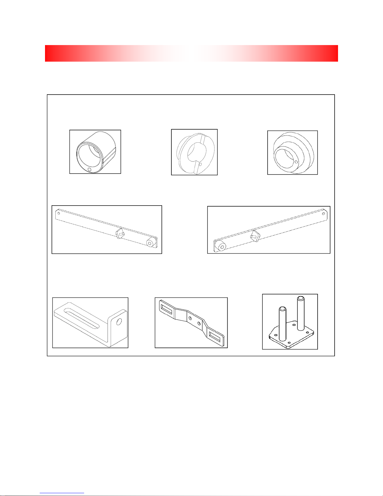
ILLUSTRATIONS
SWINGARM BUSHING-
S001315 (09-10 MODELS)
FRAME BRACE-S001266 FRAME BRACE-S001268
BODY BRACE-LB1235 LICENSE PLATE BRACKET-LB1207 ADAPTER PLATE-LP1038
SWINGARM BUSHING-LT-
S001346
SWINGARM BUSHING-RT-
S001347
2009-2013 FLH RENEGADE
6

ILLUSTRATIONS CONTINUED
MODULAR DIFFERENTIAL
LS2013-2002+ SWINGARM
GM0142 MOTOR MOUNT LINK
S001271-FRAME
2009-2013 FLH RENEGADE
7

PREPARING THE MOTORCYCLE
The following instructions are a guide to preparing the motorcycle to accept the Lehman Trike Conversion Kit. This will assist you in removing the necessary parts to install the kit. Refer to H-D service manual for detailed procedures on motorcycle disassembly.
1. Locate motorcycle year, model and serial number, as well as Lehman serial number, located inside
body, on left-side of swingarm and on warranty registration form in owner’s manual.
2. Make sure motorcycle is standing straight up and handlebars are centered. Support motorcycle under rear of transmission so it is straight up and down and handlebars are straight. The front forks or
handlebars should be anchored to hold bike.
NOTE: Use a small spirit level on rear wheel or disc brake to stand bike straight up. Any
movement of handlebars will move bike off level. Locate reference point on bike frame that
is level and check it frequently.
3. Remove seat and save mounting screw.
4. Disconnect battery.
CAUTION: Always disconnect negative battery cable first. If positive cable should conta ct a
grounded object while negative cable is installed, resulting sparks may cause an explosion.
5. Remove tour pack.
6. Raise motorcycle lift to working height.
7. Remove side stand mounting bolt and separate side stand from bracket.
8. Remove passenger footboards. Save boards and hardware for re-installation.
9. Remove side covers; they will be re-used.
10. Remove saddlebags (if equipped).
11. Remove mufflers and saddlebag mounts. Keep all muffler mounting hardware including rubber isolators located in saddlebag mounts. These parts will be re-used.
12. Support bike on center stand.
13. Disconnect airlines from shocks and remove shocks. Stand shocks upright to prevent oil leaks.
Save air valve plate and discard original shock mounting bolts.
14. Remove rear fender and save turn signal lights.
15. Remove brake line from caliper and remove caliper.
16. Remove retaining clip from rear axle and remove axle nut with 36mm socket. Axle can now be removed.
17. Remove rear wheel assembly.
18. Support transmission from below with jack and padded block.
2009-2013 FLH RENEGADE
8

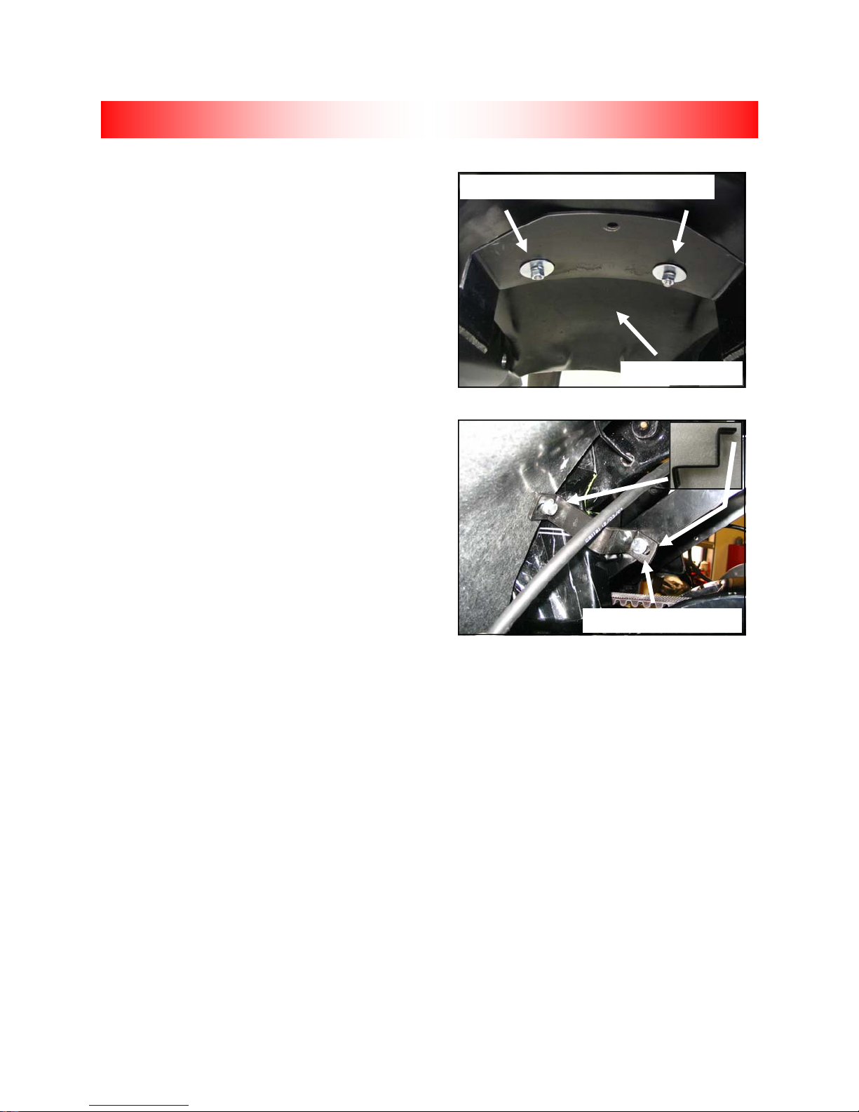
REMOVING HD SWINGARM
2009-2010 MODELS
1. See Fig. 1. Remove (2) bolts to free swingarm
fork bracket from left side of motorcycle frame.
2. Release rear brake line hose and rear wheel speed
sensor (if ABS equipped) from cable clips on right
side of swingarm.
3. Remove decorative chrome plug from right side.
NOTE: For best results, use an air impact
wrench to remove right-side nut. Applying heat
to right-side nut may also improve removal. If
left-side nut loosens first, remove left-side nut
and use double nuts to hold pivot shaft while
removing right-side nut.
4. See Fig. 2. Hold left-side nut and remove right
side nut from end of pivot shaft. Remove and
discard cup washer.
5. Using a suitable punch, tap pivot shaft toward
left side of motorcycle.
6. See Fig. 1. Pull pivot shaft assembly with nut,
cup washer, rubber mount and outer spacer out
of transmission mount and left side fork. Hold
shaft in padded vise and remove LH nut. Discard LH cup washer.
7. Remove outer spacer from right side of swingarm.
8. Remove rubber mount from right side.
2011+ MODELS
1. See Fig. 1. Remove (2) bolts to free swingarm fork bracket from left side of motorcycle frame.
2. Release rear brake line hose and rear wheel speed sensor (if ABS equipped) from cable clips on
right side of swingarm. Remove black plastic plug from right side.
NOTE: For best results, use an air impact wrench to remove right-side bolt. Applying heat to
right-side bolt may also improve removal. If left-side bolt loosens first, use a ¾” socke t to
hold LH pivot shaft outer spacer while removing right-side bolt.
3. See Fig. 2. Hold left-side bolt and remove right side bolt from end of pivot shaft.
4. Using a suitable punch, tap pivot shaft toward left side of motorcycle.
5. See Fig. 1. Pull pivot shaft assembly with outer spacer and rubber mount out of transmission mount
and left side fork. Hold shaft in padded vise and remove LH bolt.
6. Remove outer spacer from right side of swingarm. Remove rubber mount from right side.
Pivot shaft nut
Right-side mount
Fig. 1
LH Fork bracket bolts
Fig. 2
2009-2013 FLH RENEGADE
9

REMOVING H-D SWINGARM
TRIMMING EXHAUST
NOTE: Trimming rear head pipes is more
convenient while swingarm is removed
from frame.
1. Remove LH and RH rear heat shields.
2. See Fig. 4. Using an appropriate cutting tool,
cut 1 5/8” from end of both rear head pipes.
3. Reinstall LH heat shield after cut. Shield will
be placed 1/4” to 1/2” forward to gain clearance for extension pipe installation.
4. Install RH heat shield.
Fig. 4
2009-2013 FLH RENEGADE
10

INSTALLING LEHMAN SWINGARM
NOTE: Swingarm pivot shaft components are different between
2009-10 and 2011+ models. Be sure to use the correct procedu re
for your specific model year. See Fig. 1. Swingarm pivot shaft
bushings for 2011 models (S001661) will have a larger inside diameter.
Fig. 1
2009-2010 Models
NOTE: If all original components of H-D swingarm are in good
working order, they may be re-used.
1. Press bearing assemblies out of HD swingarm using appropriate
press collar. Refer to HD service manual.
NOTE: Make sure swingarm bore is clean where bearing w ill
be pressed in.
2. Press bearings into Lehman swingarm following H-D service man
ual procedure (H-D tool # HD-45327). H-D tool will set bearings at
correct location in Lehman swingarm collar.
3. See Fig. 1 & Fig 2. OEM cup washers will be replaced by new
swingarm reinforcement bushings (S001346-LH, S001347-RH &
S001315).
4. See Fig. 3. Install RH swingarm reinforcement bushings (S001347 & S001315) into original rubber mounts. Be
sure to align offset in mount and bushings.
5. Install Lehman swingarm with word “TOP” (stamped into swingarm collar) facing upward.
6. See Fig. 3. Assemble parts for LH side (S001346 & S001315) as shown.
7. See Fig. 3. Re-install LH swingarm fork bracket. Apply Loctite 242 and torque bolts to 55 ft.-lbs.
8. Apply Loctite 242 to pivot shaft nuts and install. Torque swingarm pivot shaft nuts to 55 ft.-lbs and
reinstall chrome caps.
NOTE: Refer to HD service manual for swingarm installation procedures and torque specifications for specific model of motorcycle.
Verify swingarm assembly moves freely with no side to side play. Light resistance when moving up
9.
and down is normal.
Fig. 3
Fig. 2
2009-2013 FLH RENEGADE
11

INSTALLING LEHMAN SWINGARM
2011+ Models
NOTE: If all original components of H-D swingarm are in good working order, they may be re used.
1. Press bearing assemblies out of HD swingarm using appropriate press collar. Refer to HD service
manual.
NOTE: Make sure swingarm bore is clean where bearing will be pressed in.
2. Press bearings into Lehman swingarm following H-D service manual procedure (H-D tool # HD-
45327). H-D tool will set bearings at correct location in Lehman swingarm collar.
3. See Fig. 1 & Fig 2 on previous page. Swingarm reinforcement bushings (S001346-LH, S001347-
RH & S001661).
4. See Fig. 4. Install RH swingarm reinforcement bushings (S001347 & S001661) into original rubber
mounts. Be sure to align offset in mount and bushings.
5. Install Lehman swingarm with word “TOP” (stamped into swingarm collar) facing upward.
6. See Fig. 4. Assemble parts for LH side (S001346 & S001661) as shown.
7. See Fig. 4. Re-install LH swingarm fork bracket. Apply Loctite 242 and torque bolts to 55 ft.-lbs.
8. Apply Loctite 242 to pivot shaft bolts and install. Torque swingarm pivot shaft bolts to 55 ft.-lbs.
9. See Fig. 4. Discard OEM black plastic pivot shaft plugs and replace with S001662 chrome caps.
NOTE: Refer to H-D service manual for swingarm installation procedures and torque specifi
cations for specific model of motorcycle.
10. Verify swingarm assembly moves freely with no side to side play. Light resistance when moving up
and down is normal.
Fig. 4
2009-2013 FLH RENEGADE
12

Top Motor Mount Link Removal: 2009+ Models
NOTE: For 2009+ models, do not disturb
OEM head bolts or lower engine mount bolt.
MOTOR MOUNT LINKS
1. See Fig. 1. OEM top motor mount link will be
replaced with Lehman Motor Mount Link.
2. See Fig. 2. Remove OEM motor mount link.
3. Save all mounting hardware.
Lehman Motor Mount Link
NOTE: Refer to H-D service manual for
proper removal and installation procedures
for all motor mounts.
4. Adjust Lehman motor mount link to same distance from center of hole to center of hole as
OEM motor mount link.
• (1) Upper Engine Stabilizer Link– GM0142
NOTE: Locate position of eyelet holes and
alignment of OEM link. Lehman link must be
adjusted same as OEM link; when link is adjusted, use Loctite 262 and secure lock nuts
in place.
5. Install Lehman link using existing OEM bolts,
blue Loctite 242 and supplied motor mount link
shims. Reinstall OEM washer below link on RH
side.
NOTE: Be sure to shim both sides of link ends.
6. Torque OEM bolts to 33 ft. lbs.
Fig. 1
Lehman motor mount link
OEM Top motor mount link
Fig. 2
Lehman link installed
2009-2013 FLH RENEGADE
13

DIFFERENTIAL
Differential Installation
1. See Fig. 1. Attach LH adapter plate (LP1038) to
swingarm as shown. Leave hardware loose.
2. See Fig. 2. Attach RH adapter plate to swin-
garm as shown with park brake bracket mounted
to lower holes. Leave hardware loose.
3. See Fig. 1 and 2. Install 3/8” nut to adjuster bolt
and thread into adapter plate from backside. Run
bolt completely into adapter plate.
Fig. 1
Fig. 2
2009-2013 FLH RENEGADE
14

DIFFERENTIAL CONTINUED
4. See Fig. 3 and 4. Loosely install hardware to
pinch blocks before installing differential to
swingarm.
NOTE: Shock plate orientation is different
on 09+ models. Make sure shock mount
hole on rear of plate is towards the top.
Fig. 3
Hole towards top
Fig. 4
Hole
towards
top
2009-2013 FLH RENEGADE
15

DIFFERENTIAL CONTINUED
5. Support swingarm with jack stands.
6. See Fig. 5. With differential assembly on lift,
slide belt over LH axle tube and against center
housing.
7. See Fig. 5. Set differential assembly on swin-
garm adapter plates. Slide differential as far
forward as possible. Set jack stands under
axle tubes.
8. Tighten pinch block hardware just enough to
allow differential to slide on swingarm adapter
plates.
9. See Fig. 5. Remove upper, lower and rear
housing plates.
10. See Fig. 6. Carefully slide belt over pulley.
11. Reinstall housing plates with original hardware
using Loctite 242. Install all hardware before
tightening. Torque hardware to 17 ft. lbs.
Fig. 5
Remove plates
Fig. 6
Install belt
2009-2013 FLH RENEGADE
16

DIFFERENTIAL CONTINUED
12. See Fig. 10. Remove RH front plate hardware
and install tapered washers (S001784) into
holes on RH side before installing brace.
13. Bolt rear half of differential brace to housing
using bolts (CB1939).
14. See Fig. 11. Bolt front half of differential brace
to top of swingarm gusset with a 3/8” x 1” bolt,
flat washers and lock nut.
Note: Do not bolt down brace until belt tensioning is completed.
15. Tighten bolts in following order:
a. Front half of brace to swingarm gusset.
Torque bolts to 35 ft. lbs.
b. Rear half of brace to differential housing.
Torque bolt to 25 ft. lbs.
c. Torque LH front plate bolts to 17 ft. lbs.
Fig. 7
Tapered washers
Fig. 8
2009-2013 FLH RENEGADE
17

BELT TENSIONING AND TRACKING
1. Center differential to motorcycle frame– this is critical for proper body and seat pan alignment.
Make sure distance is within 1/16” from side to side.
2. Level swingarm to motorcycle frame. This will help achieve proper ride height and is critical for
proper belt tensioning.
3. See Fig. 1. Using adjusters, push differential assembly back until belt has about 3/8” slack with 10
lbs. pressure at midpoint of bottom run. Measure between adapter plates and pinch blocks to en-
sure that distances are equal.
4. Rotate pulleys forward for at least 3 revolutions of rear pulley by pulling
backwards on bottom run of belt. Pull belt
straight back to get an accurate reading. Check
that belt is running about 0.030” from flange on
rear pulley. Belt may ride next to flange as long
as it’s not trying to climb.
5. Tighten socket head screws (8) that hold adapter
plates to swingarm and torque to 35 ft. lbs.
6. Once tracking is obtained, re-check belt tension.
Raise and lower differential assembly slowly with a jack while checking belt tension. When tightest
position is located, apply 10 lbs. force at midpoint of lower strand of belt. Correct deflection for
various models is as follows:
Fig. 1
MODEL INCHES MILLIMETERS
FLHX 1/4-5/16 6.4-7.9
All other FLH models 3/8-7/16 9.5-11.1
7. Increase or reduce belt deflection by turning adjuster screw on each side in or out an equal number
of turns.
8. Look along top of belt to check belt alignment on front pulley. There should be about 0.030” clearance between pulley flange and belt. Check rear alignment and belt tension again if adjustment is
required.
NOTE: If necessary, apply chalk to edge of belt to aid in getting proper clearance be tween
belt and pulley flanges. If visible clearance cannot be obtained, be sure belt is not climbing
up the side of pulleys or squeaking as belt is rotated.
9. After all adjustments are made, tighten adjuster lock nuts and tighten pinch block bolts. Tighten
pinch blocks in a criss-cross pattern. Go over both sides at least 2 times to seat blocks over pins.
Torque bolts to 25 ft. lbs.
2009-2013 FLH RENEGADE
18

BRAKE SYSTEMS
Disc Brakes
CAUTION: Brakes are a critical safety component of the trike. Verify all brake components
have been properly installed before test riding.
Improper brake operation could result in death
or serious injury. Do not allow dirt or debris to
enter master cylinder reservoir. New brake
pads and rotors will have a break-in period before optimum brake operation is achieved.
Note: FOR ABS DISABLE, SEE PAGE 21
Brake System
1. See Fig. 1. Attach brass tee to differential
brace using the following hardware.
• (1) Brass Tee– CF5105
• (1) Spacer– S001530
• (2) 1/4” x 1-3/4” Hex Bolt– CB1100
• (2) 1/4” Flat Washers– CW2005
• (2) 1/4” Lock Nut– CN3042
2. See Fig. 1. Install original brake line from
master cyclinder and rear braided lines to
brass tee using the following hardware. Torque
banjo bolt to 16 ft. lbs.
• (1) Banjo Bolt– S002022
• (2) Banjo Washers- GC6002
• (2) 45” M10 Braided Line– S001976
3. See Fig. 2. Install (2) braided brake lines to
rear calipers as shown. Torque bolts to 16 ft.
lbs.
• (2) M10 Banjo Bolt– CB6001
• (4) M10 Banjo Washers- GC6002
4. Secure brake lines to swingarm with cable ties.
Fig. 1
OEM line
Spacer
Fig. 2
Install brake lines to LH/RH calipers
2009-2013 FLH RENEGADE
19

BRAKE SYSTEMS CONTINUED
Note: Be sure you have correct model year reservoir extension pack before proceeding
(Reminder: packs are labeled 1997-2007 and
2008+).
5. See Fig. 3. Remove original master cylinder
reservoir cap screws and discard. Install extension to master cylinder with new extension
screws. Do not over tighten extension
screws.
Note: Verify all brake lines and hardware are
tight before bleeding system.
6. Add brake fluid (refer to OEM reservoir cap for
brake fluid requirements) to brake system and
work brakes to fill lines.
7. Remove rubber caps on bleeder valves. Install
clear brake bleeder hose over bleeder valve on
caliper.
8. Pump brake pedal to build hydraulic pressure.
9. While holding the brake pedal, open bleeder
valve to release pressure and remove air from
system. Repeat bleeding on both calipers until
fluid is solid without bubbles in bleeder hose.
10. Tighten bleeder valves and check for leaks.
11. Install master cylinder reservoir cap with new
screws. Do not over tighten cap screws.
Park Brake Assembly
1. See Fig. 4. Install park brake cable to caliper
brackets. Secure cable to bracket with cir-clip
provided on cables.
Fig. 3
Supplied cover screws
Extension screws (2008+ pack)
Fig. 4
Secure to bracket
Attach cable
2009-2013 FLH RENEGADE
20

BRAKE SYSTEMS CONTINUED
5. See Fig. 7. Remove snap ring from one side of large
clevis pin on brake lever. Hold park brake lever on its
side and push release button at end of park brake lever
to allow clevis pin to slide out.
6. See Fig. 7.Place park brake lever within park brake
bracket, ensuring ratchet is secure on cross brace. Attach with large clevis pin.
7. See Fig. 7. Attach park brake cable pulling bracket
(LB1294) to brake lever using small clevis pin (CC3106)
and cotter pin (CC4017).
8. See Fig. 8. Route left park brake cable above differen-
tial and under motorcycle frame, attaching cable ties to
cable and frame, and install in left hole in handle mount.
9. See Fig. 9. Route right park brake cable up around axle
and forward to right hole in handle mount.
10. See Fig. 9. Secure both cables to upper rear pinch block
with clamp (GC0108).
11. See Fig. 10. Secure cable retaining nuts to handle
mount with 7/8” wrench.
12. Check for tire clearance.
13. See Fig. 10. Thread one 5/16” NF nut onto each brake
cable. Place threaded end of brake cables through
holes in cable bracket. Thread second nut onto each
brake cable.
14. Adjust park brake cables at handle to engage at 3–4
clicks.
Note: Take up slack in cables before tightening ends to
ensure good adjustment range with threaded end of
brake cables.
Fig. 7
Fig. 8
Left park brake cable
Fig. 9
Cable routing
Attach clamp
Fig. 10
Cable retaining nuts
Adjuster nuts
2009-2013 FLH RENEGADE
21

BRAKE SYSTEMS-ABS MODELS
ABS Systems
1. See Fig. 1. Disconnect OEM rear brake line (black)
from ABS unit “MR”. Route brake line along lower
frame tube and above swingarm. This line will be
used for the rear brake system.
2. See Fig. 2. Re-install banjo bolt with spacer
(S001067) in ABS unit “MR” and tighten.
3. See Fig. 1. Disconnect OEM rear brake line (silver)
from ABS unit “R” and discard (brake line was disconnected from rear caliper during motorcycle disassembly).
4. See Fig. 2. Re-install banjo bolt with spacer
(S001067) in ABS unit “R” and tighten.
5. See Fig 3. Locate ABS front wheel sensor plug un-
der left side of fairing and disconnect. Secure longer
sensor plug to fairing wire bundle with cable tie
(CT1026).
6. See Fig. 4. Locate ABS rear wheel sensor plug (left
side of ABS unit). Disconnect plug, remove sensor
from right-side axle and discard.
7. Place ABS warning label above warning light indicators on fairing.
Fig. 1
From ABS to caliper (silver)
From Mas. Cyl. to ABS (black)
R
MR
Fig. 2
R
MR
Banjo bolt spacer (S001067)
Fig. 3
ABS front wheel sensor plug
2009-2013 FLH RENEGADE
Fig. 4
ABS rear wheel sensor plug
22

BRAKE SYSTEMS-ABS MODELS CONTINUED
Note: Items 7-11 can be performed during Neck Race
Preload check.
7. Remove outer fairing (refer to HD service manual).
Caution: Disabling ABS light will also disable cruise
control light.
8. See Fig. 5. Disable ABS warning light by cutting orange wire with white stripe.
9. See Fig. 6. Install 2” heat-shrink to each end of cut
wire.
10. Re-install fairing.
11. See Fig. 7. Place ABS warning label above warning
light indicators on fairing.
Fig. 5
Fig. 6
Apply heat shrink to ends of wires
Fig. 7
Place “ABS Disabled” sticker here
2009-2013 FLH RENEGADE
23

FRAME AND SUSPENSION
1. The holes in front of Lehman frame line up with
HD shock mount holes.
2. Position Lehman frame above differential and
inside motorcycle frame, lining up mounting
holes.
3. See Fig. 1. Install the following hardware in the
front frame mounting holes. Torque bolts to 75
ft.-lbs.
• (2) 1/2” X 2” bolts- CB1406
• (2) 1/2” Lock Washers– CW2061
• (2) 1/2” Flat Washers– CW2025
4. See Fig. 2. Install the following hardware in the
rear frame mounting holes. Torque bolts to 18
ft.-lbs.
• (4) 5/16” x 1” Bolts– CB1161
• (4) 5/16” Lock Washers– CW2047
• (4) 5/16” Flat Washers– CW2010
5. See Fig. 3. Install LH and RH frame straps to
upper holes in motorcycle frame using the fol-
lowing hardware. Torque bolts to 18 ft.-lbs.
• (1) LH Frame Strap– S001266
• (1) RH Frame Strap– S001268
• (2) 5/16” x 1” Bolts– CB1161
• (2) 5/16” Lock Washers– CW2047
• (2) 5/16: Flat Washers– CW2010
6. See Fig. 3. Lower frame strap mounting holes
will use the following hardware. Torque bolts to
52 ft.-lbs.
• (2) 7/16” x 1” Bolts– CB1287
• (2) 7/16” Lock Washers– CW2022
• (2) 7/16” Flat Washers– CW2053
Fig. 1
LH and RH front holes
Fig. 2
LH and RH rear holes
Fig. 3
Frame strap top mounting holes
2009-2013 FLH RENEGADE
Frame strap bottom mounting holes
24

FRAME AND SUSPENSION
7. Use original cross-over airline to connect “tee” to air
valve. Use new air line to connect two shocks together.
8. See Fig. 4. Air valve plate for front and rear shocks
must be removed and relocated. Recommended location is on right side of trike behind air deflector in location shown.
9. See Fig. 5. Air valve plate will be fastened with
stainless nuts on both sides of deflector.
10. Route airlines along bottom side of upper frame tube
and back to rear shocks.
11. Secure airline to frame with cable ties as needed.
12. Charge system with air to 20 psi and check for leaks.
13. See Fig. 6. Install Shock to lower threaded shock
plate. Torque bolt to 40 ft.-lbs. Secure bolt with lock
nut.
• (2) 1/2” X 2 x 1/4” Bolts– CB1411
• (2) 1/2” Flat Washer– CW2025
• (2) 1/2” Lock Nut
14. See Fig. 6. Raise differential and install top of shock
To frame using the following hardware. Shock should
run parallel to frame tube when viewed from rear.
Torque shock bolts to 40 ft.-lbs.
• (2) 1/2” X 2 x 1/4” Bolts– CB1411
• (2) 1/2” Lock Washer– CW2060
• (2) 1/2” Flat Washer– CW2025
Fig. 6
Fig. 4
Relocate air valve plate
Fig. 5
Air valve plate
mounting hardware
2009-2013 FLH RENEGADE
25

EXHAUST
NOTE: Exhaust pipes are marked “L” and “R.”
1. See Fig. 1. Install exhaust clamp (GC1016) on front end of LH extension pipe (S001309) and slide
onto LH OEM pipe.
2. Install exhaust clamp (GC1016) on front end of RH extension pipe (S001273) and slide onto RH
OEM pipe.
3. Install rubber mount into Lehman frame.
4. Slide OEM muffler mounting bracket through rubber mount.
5. Slide mufflers with clamps in place over Lehman extension pipes.
6. Ensure mufflers are even on both sides.
7. Torque exhaust clamps to 40 ft.-lbs.
8. Use OEM mounting hardware to secure muffler to mounting bracket on Lehman frame. Torque bolts
to 144 in.-lbs.
Fig. 1
ITEM PART # QTY. DESCRIPTION
0 OEM PARTS
1 S001273 1 PIPE, EXT., RIGHT-HAND
2 S001309 1 PIPE, EXT., LEFT-HAND
3 GC1016 2 CLAMP, EXHAUST
2009-2013 FLH RENEGADE
26

LIGHTS AND WIRING
Lights and Wiring
Caution: Use care with painted surfaces
1. See Fig. 1. Drill 15/16” hole for turn signal on flat
below taillight. Center turn signal with inside edge
of taillights. Mount H-D turn signals using original
bolts with supplied washers (CW2001).
NOTE: Do not over tighten taillight mounting hardware. Damage to housing may occur.
2. See Fig 2. Mount taillight assemblies to body with
gaskets. Attach ground wire to stud with flange nut
after taillight mounting hardware is installed.
• (2) Taillight Assembly-S002204
• (2) Gaskets– BG0200
• (4) 1/4” Flat Washer– CW2006
• (4) Lock washer– Provided with light
• (4) Nut– Provided with light
• (2) 1/4” Flange Nut– CN3007
3. See Fig’s 3 & 4. If required- Install female terminals
and male connectors to taillight wiring Use appropriate
tool for crimping terminals to wires. (Mac Tools–
TCT1028).
4. See Fig’s 3 & 4. Inspect crimps before installing into
connector. Distortion should be minimal.
Fig. 1
Mount signal
to body
Fig. 2
Attach ground wire to stud
Fig. 3
Female Terminal
Insulation crimp
2009-2013 FLH RENEGADE
Wire core crimp
Fig. 4
1
2
3
27

LIGHTS AND WIRING
5. See Fig. 5. Install license plate bracket to door
with 1/4” x 1” bolts, washers, lock nuts and rubber
washers. Use rubber washers between bracket
and door. Install U-nuts to bracket
• (2) 1/4” x 1” Button head bolt (CB1086)
• (2) 1/4” Rubber washer (FG1002)
• (2) 1/4” Flat washer (CW2005)
• (2) 1/4” Lock nut (CN3040)
• (2) 1/4” U-nut (CN3301)
6. See Fig. 6. Install license plate light and support
plate to bracket using (2) 1/4” x 1 bolts.
See Fig. 5. Run wiring through lower hole in door .
• (1) License plate light (S001469)
• (1) Support plate (S001601)
• (2) 1/4” x 1 Button head bolt (CB1086)
• (2) M6 Flat washer- CW2175
7. See Fig. 6. Install lower license plate mounting
hardware into place on support bracket using 1/4”
x .50” bolts and (2) lock nuts
Fig. 5
Install rubber washers
between bracket and door
U-nut
Install wire through lower hole
Fig. 6
• (2) 1/4” x .50 Button head bolt (CS4032)
• (2) 1/4” Lock nut (CN3040)
8. Solder and heat shrink light wiring to trunk wiring
harness. Attach wire as follows-
• Black wire on light to Black wire on
trunk harness
• Red wire on light to Red wire on trunk
harness
9. Seal wiring through door with silicone (Ultra
Black).
2009-2013 FLH RENEGADE
28

Renegade Wiring Harness
1. See Fig.’s 1-2. Attach wiring harness to body
clips on underside of body. The Purple turn signal wire will go to the LH side. The Brown turn
signal wire will go to the RH side.
2. Connect 8 position connector on wiring harness
(Fig. 3) to OEM harness, located under rider
seat at rear of OEM frame.
Body clip
LIGHTS AND WIRING CONTINUED
Fig. 2
Fig. 1
Taillight connector
Light bar
connector
on RH side
Body clips
Fig. 3
8-position connector on wiring harness-main
License plate connector
6-position connector on wiring harness for trailer
3. See Fig.’s 4-5. Before connecting license plate and light bar (optional) to harness, terminals and
connectors will need to be installed to each before connecting to wiring harness. Use appropriate
tool for crimping terminals to wires. (Mac Tools– TCT1028, Blue Point– PWC47 or H-D 41609).
4. See Fig. 5. Inspect crimps before installing into connector. Distortion should be minimal.
Fig. 4
Male terminal
Fig. 5
Insulation crimp
Wire core crimp
Female terminal
2009-2013 FLH RENEGADE
29

LIGHTS AND WIRING CONTINUED
6 position connector for
trailer-GH0023-2
8 position connector
under seat-GH0023-1
Included in bag
Fig. 8
Left brake
light-GH0023-4
Left turn signalGH0023-4
License plate connectorGH0023-3
Right brake
light-GH0023-3
Right turn signalGH0023-4
Light barGH0023-5
Wiring Diagram
Red/White
Tracer
Purple
Blue
Fig. 9
Orange/White
Tracer
Brown
Black
Orange/White
Tracer
2009-2013 FLH RENEGADE
Black
30

SIDE COVER MODIFICATION
1. See Fig. 1. Place side cover template
(S001324) as shown with a 90° bend at center;
make sure template rests firmly against mounting peg.
2. See Fig. 2. Mark grommet access hole and
side-cover cut-out as shown.
3. Using 1/8” drill bit, make a starter hole for grommet access hole.
4. Using a 7/16” drill bit, drill a 7/16” hole for grommet access hole.
5. Install rubber grommet (S001323) in grommet
access hole. Secure with glue if necessary.
6. Using appropriate cutting tool, cut side-cover
along template mark.
7. See Fig. 3. Trim upper, rear mounting peg
leaving 1/4” remaining.
8. Repeat steps 1-7 for other side.
Fig. 1
Set template firmly against peg
Template should be at 90°
Fig. 2
Mark side-cover cut-out
Mark grommet access hole
Fig. 3
Trim mounting peg to 1/4”
2009-2013 FLH RENEGADE
31
BODY
WARNING: To meet DOT and MOT requirements one of the following must be installed
on all Lehman Trikes: stock grab handles,
stock grab strap or Lehman-supplied grab
handles. Please contact Lehman Trikes if
you require replacement grab handles.
1. Place body on trike frame.
2. Route emergency trunk release cable along H-D
frame and secure behind LH side cover.
3. Install (1) rubber body washer (CW2097) between body and frame mounting tabs.
4. Place a thin strip of weather seal around seat
shell.
• (1) Weather Seal– CW2505
• (1) 09+ Seat Shell– S001317
5. Insert (2) studs with Red Loctite (262) into seat
shell inserts.
• (2) 1/4” x 1” Studs– S001343
6. See Fig. 1. Install seat shell to support on frame
using the following hardware. Leave bolts loose.
• (2) 1/4” Fender Washers– CW2108
• (2) 1/4” Lock Washers– CW2040
• (2) 1/4” Lock Nuts– CN3041
7. See Fig. 2. Install left and right body support
brackets with 90° bend against frame strap; attach front of body mount bracket into seat shell inserting rubber washer between bracket and body. Attach brackets with the following hardware. Leave
bolts loose.
• (2) Rubber Washer– CW2096
• (2) 1/4” 1” Bolts– CB1085
• (2) 1/4” Lock Washers– CW2040
• (2) 1/4” Flat Washers– CW2005
8. Attach rear of body mount bracket to frame strap using the following hardware. Leave bolts loose.
• (2) 1/4” x 3/4” Bolts– CB1081
• (2) 1/4” Lock Washers– CW2040
• (2) 1/4” Flat Washers– CW2005
Underside of frame-seat shell hardware
Fig. 1
Seat shell support
Fig. 2
90° bend to frame strap
2009-2013 FLH RENEGADE
32
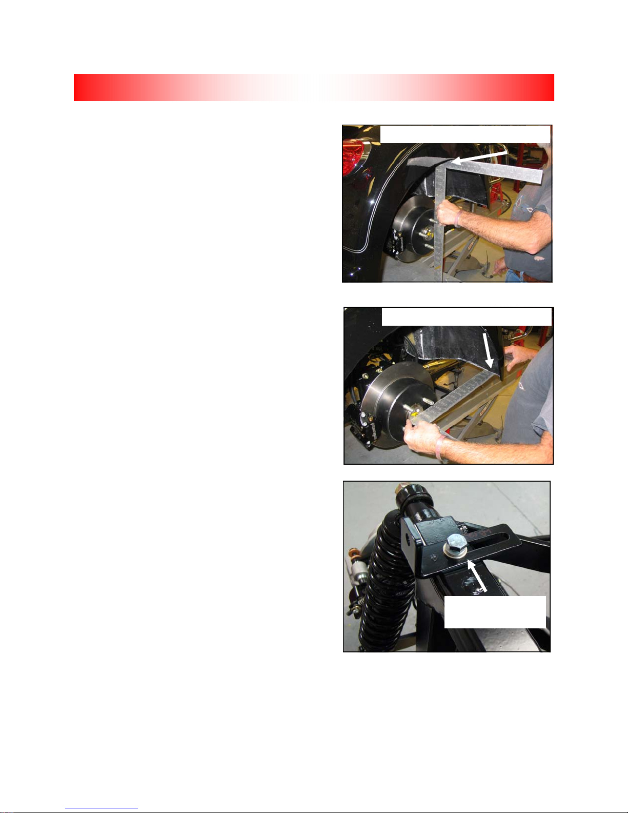
BODY CONTINUED
9. See Fig. 3. Center body to differential from side
to side until equal measurements are achieved on
both sides.
10. See Fig. 4. Center body front to back measuring
from rear axle flange to front of fender until equal
measurements are achieved on both sides.
11. Allow at least 1/2” gap between front of seat shell
and side cover for side cover removal.
12. Tighten hardware in this order: seat shell bolts,
front body mount bolts into seat shell; torque front
body mount bolts to 6 ft-lbs.
13. From underside of body, drill a 1/4” hole in body
through each of four mounting tabs. Keep hole
centered in slots on frame.
14. Fasten body to Lehman frame as follows: Head
of bolt will be inside trunk.
• (4) 1/4” x 1-1/2” Button Head Bolts- CS4031
• (4) 1/4” x 1 1/4” Fender Washers- CW2108
• (4) Foam Sealing Washers- FG1002
• (4) 1/4” Flat Washers- CW2007
• (4) 1/4” Lock Nuts- CN3041
15. Recheck body alignment; adjust accordingly.
16. Tighten body mount brackets to frame straps.
Torque bolts to 8 ft.-lbs.
17. See Fig. 5. Install upper body braces (LB1235)
by attaching slotted side on top of Lehman frame using the following hardware. Leave hardware loose.
• (2) Body Brace– LB1235
• (2) 5/16” x 1” Bolts– CB1161
• (2) 5/16” Lock Washers– CW2047
• (2) 5/16” Flat Washers– CW2010
18. Slide bracket against trunk, mark and drill 1/4” hole.
19. Attach bracket to body using the following hardware.
• (2) 1/4” x 1-1/2” button head bolts- CS4031
• (2) 1/4” x 1 1/4” fender washers CW2108
• (2) Foam Sealing Washers FG1002
• (2) 1/4” Flat Washers- CW2007
• (2) 1/4” Lock Nuts- CN3041
20. Tighten 5/16” hardware into place on trike frame.
21. Verify all body mounting hardware is tight.
Fig. 3
Equal measurements on both sides
Fig. 4
Equal measurements on both sides
Fig. 5
Body brace attached
to frame
2009-2013 FLH RENEGADE
33

TOUR PACK
NOTE: See Fig. 1. Adapter plate (S001307)
angled ears determine rearward position and
straight and 90° edges determine forward
position.
1. Install tour pack adapter plate to base plate us-
ing button head bolts. Torque bolts to 8 ft.-lbs.
• (1) Adapter Plate- S001307
• (1) Base Plate– S001090
• (4) 1/4” x 5/8” Button Head Bolts– CS4089
2. See Fig. 1. Set base assembly on bench and
place tour pack on base assembly.
3. See Fig. 2. Open tour pack lid and temporarily
fasten tour pack to base assembly using (2) of
the (4) 1/4” x 7/8” button head bolts (CS4094).
4. Set tour pack and assembly on body.
5. Center tour pack to body, seat and grab handle.
6. Mark holes in body with scribe or equivalent.
7. Remove tour pack and assembly from body.
8. Drill holes in body with 5/16” drill bit and drill.
9. Remove tour pack from base assembly.
10. See Fig. 3. Place rubber gaskets on body and
install base assembly using the following hardware.
• (4) 5/16” x 1-1/4” Button Head Bolts– CB1163
• (4) 5/16” Lock Washers– CW2046
• (4) 5/16” Flat Washers– CW2009
11. Install tour pack support brackets inside trunk
body and fasten plates to assembly hardware.
Torque bolts to 17 ft.-lbs.
• (1) Tour Pack Support Brackets- S001091
12. Reinstall tour pack and fasten tour pack with all
hardware. Torque bolts to 8 ft.-lbs.
13. Reinstall all tour pack wiring in proper locations.
14.NOTE: Tour pack ground strap will need
to be relocated to proper ground.
14. Reinstall tour pack liner.
Fig. 1
Rearward
Adaptor plate-S001307
Fig. 2
Temporarily fasten tour pack with hardware
Fig. 3
Base assembly on body
Forward
2009-2013 FLH RENEGADE
34

TRUNK DOOR
Trunk Door Installation
Note: Lip on weather seal will face away
from door opening; top of seal is flush with
top of door.
1. See Fig. 1. Install door seal around edge of
body, starting at center on bottom and following trunk opening. Trim seal ends straight
with scissors; glue ends together when finished.
• (6’) Door Seal– CW2536
2. See Fig. 2. Insert lanyard through top bend
on cable stop bracket. Make a small loop in
the end of lanyard and crimp using aluminum clip (see inset in Fig. 2). There should be
7-1/2” between the crimp and pre-made end of
lanyard. Verify both lanyards match before
crimping.
• (2) Door Lanyard– S001686
• (2) Cable Bracket– FB1036
• (2) Aluminum Crimp– CC1900
3. Apply masking tape to body just below hinge
mounting holes to prevent scratching of paint by
hinges.
Fig. 1
Top of seal is flush with door opening
Lip on weather seal
Fig. 2
Insert through bracket
Loop and crimp
4. See Fig. 3.Install door hinges and stop cable
brackets to body with hinge gaskets underneath
hinge using 10/32” x 1” screws and plated star
nuts.
• (2) Door Hinge– GH0903
• (2) Hinge Gaskets– FG1003
• (4) 10/32” x 1” Phillips Screws– CS4024-0
• (4) Plated Star Lock Nuts– CN1898
5. Fasten door to hinges using 10/32” x 3/8”
screws.
• (4) 10/32 x 3/8” Phillips Screws– CS4024-1
6. Attach lanyard to door using shoulder screws
with M6 flat washer under cable end.
• (2) 1/4” x .438 Shoulder Screws– CB1151
• (2) M6 Flat Washer– CW2172
7. See Fig. 3.Torque shoulder screws to 6 ft-lbs us-
ing 5/32” Allen socket.
2009-2013 FLH RENEGADE
35
Shoulder Screw
Washer under
cable end
Fig. 3

TRUNK DOOR CONTINUED
8. See Fig. 4 Install key switch through body.
9. See Fig. 4 Install latch cable bracket onto key
switch.
10. See Fig. 4 Install large nut to rear door key
switch using 7/8” wrench and adjust bracket in
an upright position.
11. See Fig. 4.Attach cable to key mechanism while
key is in vertical position with head of screw from
cable facing out.
12. See Fig. 5. Install striker pin to striker bracket
using 5/16” lock nut .
• (1) Striker Pin– GL2041
• (1) Striker Bracket– LB1297
• (1) 5/16” Lock Nut– CN3045
13. Attach striker pin bracket to door using 1/4”
lock washers and 1/4” bolts .
• (2) 1/4” x 1/2” Bolts– CB1075
• (2) 1/4” Lock Washers– CW2040
14. Install Renegade badge to bottom right side
of door. Install Lehman badge GB1320 to
bottom left side of door.
• (1) Renegade Badge– GB1324
• (1) Lehman Badge– GB1320
15. Cut license plate wire from body to length to
reach body wiring as needed.
16. Install shrink tubing over license plate wires.
17. Strip and solder ends of license plate wires from the body and door together.
18. Slide shrink tubing over soldered connections and heat.
19. Solder and heat shrink light wiring to trunk wiring harness. Attach wire as follows-
Cable bracket
Fig. 4
Fig. 5
Key switch
Striker pin
and bracket
• White wire on light to Black wire on trunk harness
• Gray wire on light to Red wire on trunk harness
20. Secure wiring to trunk door.
2009-2013 FLH RENEGADE
36

DOOR ADJUSTMENT
Fig. 1
2009-2013 FLH RENEGADE
37

DOOR ADJUSTMENT CONTINUED
Fig. 2
Fig. 18
2009-2013 FLH RENEGADE
38

FINAL ASSEMBLY
Final Assembly
1. Install grab handle to seat shell using the following hardware. Torque bolts to 8 ft.-lbs.
• (1) Grab Handle– LH1026
• (2) 1/4” x 3/4” Bolts– CB1081
• (2) 1/4” Lock Washers– CW2040
• (2) 1/4” Flat Washers– CW2005
2. Install seat to fender using original H-D mounting hardware.
Note: Make sure insert in fender is free of paint before installing screw.
3. Install wheels. Torque wire wheel lug nuts to 75 ft.-lbs. and aluminum wheel lug nuts to 85 ft.-lbs.
Install center caps (if applicable).
Caution: Do not use an impact wrench when installing lug nuts.
4. Reflectors can be installed to body. See Fig. 1. Install rear reflectors 3” below taillights on body.
See Fig. 2. Install side reflectors using wheel center caps as a reference, 1/4” above wheel opening
on body.
Fig. 1 Fig. 2
2009-2013 FLH RENEGADE
39

STEERING NECK
Neck Race Preload,
Steering head should be approximately twice as tight as factory specifications for a trike conversion.
Refer to H-D service manual for adjustment procedure.
Caution: Do not tighten bolts past factory specifications. Only bearing adjustment collar should
be tightened past factory settings.
2009-2013 FLH RENEGADE
40

TORQUE SPECIFICATIONS
Swingarm pivot shaft (09+ models) 55 ft. lbs.
LH fork bracket 55 ft. lbs.
Park brake bracket 35 ft. lbs.
Pinch block bolts 25 ft. lbs.
LP1038 Adapter Plate 35 ft. lbs.
Banjo bolts 16 ft. lbs.
Torque link to engine/frame 33 ft.-lbs.
Lehman frame, front 75 ft. lbs.
Rear frame bolts 18 ft. lbs.
Frame brace, top 18 ft. lbs.
Frame brace, lower 52 ft. lbs.
Shock bolts 40 ft. lbs.
Wheels/aluminum 85 ft. lbs.
Wheels/wire 75 ft. lbs.
Caliper to bracket bolts 38 ft. lbs.
Caliper bracket to axle flange bolts 38ft. lbs.
Differential bearing bridge bolts 38ft. lbs.
Axle flange bolts 38 ft. lbs.
2009-2013 FLH RENEGADE
41

FINAL TRIKE INSPECTION
1. Reflectors Installed
2. Lights and horn work
3. Park brake operation
4. Engine/Transmission oil levels
5. Belt tension 3/8”-7/16”
6. Wheel torque 85 ft. lbs. (75 ft. lbs.-wire)
7. Rear tire pressure 26 psi
8. Front tire pressure 36 psi
9. Trunk clean and dry
10. Trunk door seals and operates smoothly
11. Rear shocks set @ 20 psi
12. Heat shields, side covers
13. Renegade/Lehman badge installed
14. Accessories (if applicable)
15. No paint defects
16. Warranty/owner’s manual included
Good Rework
□ □
□ □
□ □
□ □
□ □
□ □
□ □
□ □
□ □
□ □
□ □
□ □
□ □
□ □
□ □
□ □
2009-2013 FLH RENEGADE
42
 Loading...