

LEGRAND Wattstopper LMRC-101 User Manual
Wattstopper
Daylighting
Sensor
J-Box
Digital Lighting Management Single Relay Room Controller
Gestion numérique de l’éclairage Contrôleur de pièce à relais unique
No: 22893 – 11/17 rev. 2
Catalog Number • Numéro de Catalogue • Número de Catálogo: LMRC-101
Country of Origin: Made in China • Pays d’origine: Fabriqué en Chine • País de origen: Hecho en China
This unit is pre-set for Plug n’ Go™ operation, adjustment is optional.
For full operational details, adjustment and more features of the product, see the
DLM System Installation Guide provided with Wattstopper room controllers, and also
available at www.legrand.us/wattstopper.
Installation shall be in accordance with all applicable regulations, local and NEC
codes. Wire connections shall be rated suitable for the wire size (lead and building
wiring) employed.
For Class 2 DLM devices and device wiring: To be connected to a Class 2 power
source only. Do not reclassify and install as Class 1, or Power and Lighting Wiring.
WARNING: Do not install to cover a junction box having Class 1, 3 or Power and
Lighting Circuits.
Control de la iluminación digital Controlador de habitación de relé simple
Quick Start Guide • Guide de démarrage rapide • Guía de inicio rápido
Input Voltage ....... Single Phase 120/230/240/277VAC, 50/60Hz
Load Requirements
Incandescent ........................................20A @ 120VAC
Ballast ...........................................20A @ 120/277VAC
Motor ............................................ 1Hp @ 120/240VAC
Output ....................................................... 150mA @ 24VDC
DLM Local Network Characteristics:
Provides low voltage power over Cat 5e cable (LMRJ).
Supports up to 24 communicating devices, including 4
LMRC‑10x or LMPL‑101 max per each DLM Local Network.
Free topology up to 1,000ft of low voltage cable.
Environment:
Operating Temperature .........32° to 104°F (0° to 40°C)
Storage Temperature ...........23° to 176°F (‑5° to 80°C)
Relative Humidity ...............5 to 95% (non condensing)
Patent Pending
®
SPECIFICATIONS
PLACEMENT EXAMPLE
DLM Local Network
(low voltage, Class 2)
Corner Mount
Occupancy
Sensor
J Box
To
Load
Ceiling Mount
Occupancy
Sensor
Room
Controller
LMRJ cables
Switch
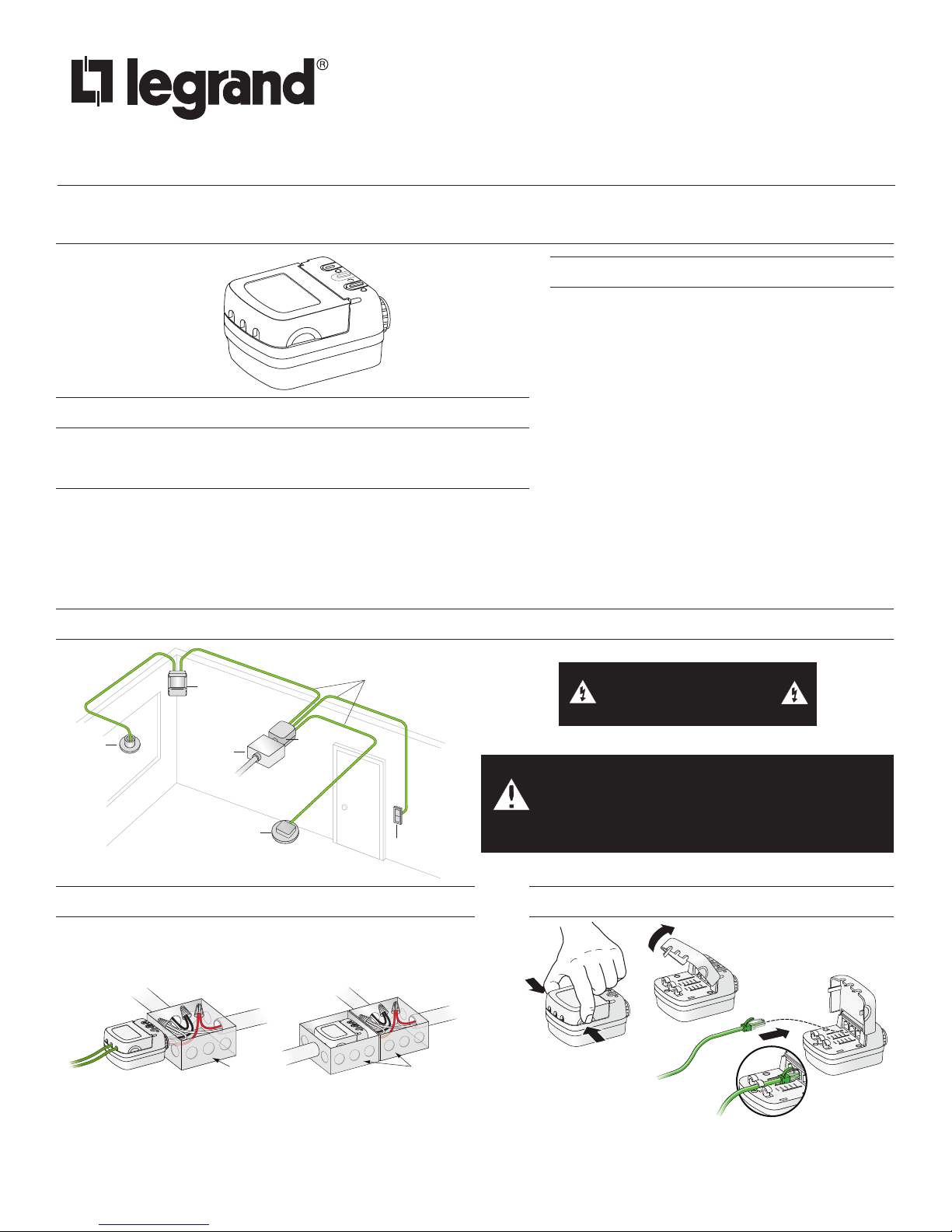
MOUNTING THE CONTROLLER
The LMRC‑101 room controller can be mounted external to either
a 4”x 4” or 4‑11/16 x 4‑11/16 junction box, placing it in the plenum
space or mounted directly inside a 4‑11/16 x 4‑11/16 junction box.
Line
Load
Line
Load
J-Boxes
WARNING: TURN THE
POWER OFF AT THE CIRCUIT
BREAKER BEFORE WIRING.
CAUTION: TO CONNECT A COMPUTER TO THE
DLM LOCAL NETWORK USE THE LMCI-100. NEVER
CONNECT THE DLM LOCAL NETWORK
TO AN ETHERNET PORT – IT MAY DAMAGE
COMPUTERS AND OTHER CONNECTED EQUIPMENT.
ATTACHING CABLES
Outside a 4” x 4” or
4 11/16 x 4‑11/16 box
Inside a 4 11/16 x 4‑11/16 box
Remove rubber jack covers if using all 3 RJ45 receptacles.
Leave covers in place for all unused receptacles.
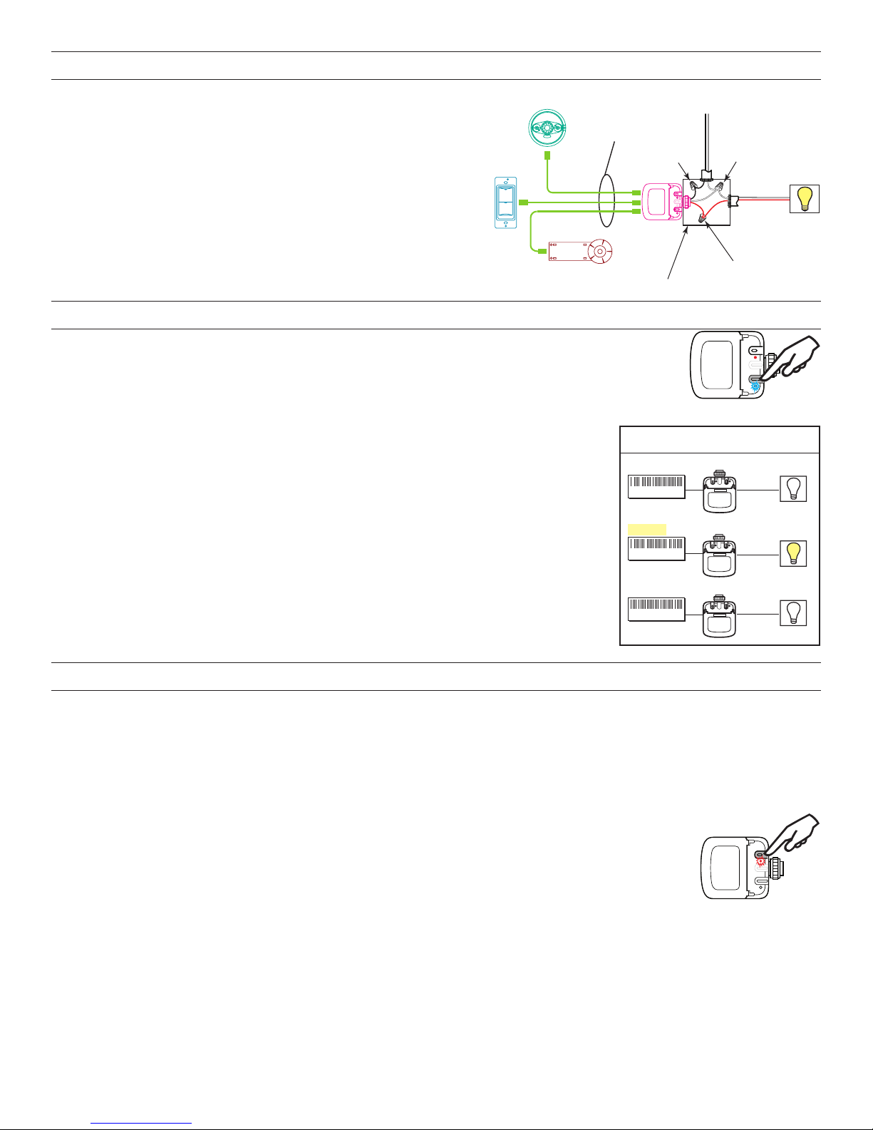
CONNECTIVITY
J-Box
Switch
Ceiling Mount
The LMRC‑101 communicates to all other DLM devices connected to the
DLM Local Network. Connection drawings are for example only. The low
voltage LMRJ cables can connect to any DLM device with an open RJ45
receptacle.
Sensor
DLM Local Network
Low Voltage
LMRJ Cables
All line voltage wiring is #12 AWG.
Daylight Sensor
PLUG N’ GO OPERATION (PNG)
Plug n’ Go supports the most energy efficient control strategy. For example, if one load,
one switch and one occupancy sensor are connected to the DLM local network, the system
operates the load as Manual‑On, Automatic‑Off.
See DLM device Quick Start Guides to determine how each device affects the PNG
operation of the LMRC‑101.
Load Control Arbitration
To take full advantage of automatic PnG configuration, review these simple rules about load control
arbitration.
After the room controllers are connected to the DLM Local Network and powered up they
automatically negotiate to determine which controller becomes the Master, as well as the load
numbers for each relay on the DLM Local Network.
The Master is the controller with the most load relays. If more than one controller has the most
relays, the one with the highest serial number becomes the Master.
The LMRC‑101 has only one load . In a DLM local network with only LMRC‑101 room controllers,
the LMRC‑101 with the highest serial number is the Master, carrying Load 1 and Load 2. The next
highest serial number would have Load 3 and Load 4, and so forth.
Load ON/OFF button
Blue LED ON when
load is ON
Line/Hot
Black wire
LMRC
101
Room
Controller
Serial
Number
0458356155
Master
0458356679
0458356133
Line
Voltage
White wire
Room
Controller
LMRC-101
0458356155
LMRC-101
0458356679
LMRC-101
0458356133
Neutral
Red wire
to Load
Load
Load
Control
2
1
3
OPTIONAL UNIT ADJUSTMENT - PUSH N’ LEARN (PNL)
Load Selection Procedure
A configuration button (Config) allows access to our patented Push n’ Learn™ technology to change binding relationships between
sensors, switches and loads.
Step 1 Enter Push n’ Learn
Press and hold the Config button (on any DLM device) for 3 seconds.
The red LED on the LMRC‑101 begins to blink as does the red LED on ALL other communicating devices connected to the DLM Local
Network.
The red LEDs continue to blink until you exit PnL mode.
All loads in the room turn OFF immediately after entering PnL, then one load will turn ON. This is Load #1, which
is bound to switch button #1 and occupancy sensors as part of the Plug n’ Go factory default setting.
All switch buttons and sensors that are bound to this load have their blue LED solid ON.
Step 2 Load selection
Press and release the Config button to step through the loads connected to the DLM Local Network. As each load
turns ON note the devices (switch buttons and sensors) that are showing a bright solid blue LED. These devices
are currently bound to the load that is ON. The blue LED on the room controller or plug load controller connected to the load is also lit.
• To unbind a switch button from a load, press the switch button while its blue LED is ON bright. The blue LED goes dim to indicate
the button no longer controls the load that is currently ON.
• To unbind an occupancy sensor, press the up () or down () adjustment button while its blue LED is ON. The blue LED turns
OFF to indicate the sensor no longer controls the load that is currently ON.
Pressing the switch or up () or down () button again while the load is ON rebinds the load to the button or sensor and the blue LED
illuminates brightly.
2
Cong button &
red LED
Step 3 Exit Push n’ Learn
Luminosit
Press and hold the Config button until the red LED turns OFF, approximately 3 seconds.
TROUBLESHOOTING
Loads do not operate as expected.
LEDs on a switch or
sensor don’t light
1. Check to see that the the device is connected to the DLM Local Network.
2. Check for 24VDC input to the device: Plug in a different DLM device at the device location. If the
device does not power up, 24VDC is not present.
• Check the high voltage connections to the room controller and/or plug load controller(s).
• If high voltage connections are good and high voltage is present, recheck DLM Local Network
connections between the device and the room controller and/or plug load controller(s).
The wrong lights and
plug loads are controlled
LEDs turn ON and OFF
but load doesn’t switch
1. Configure the switch buttons and sensors to control the desired loads using the Push n’ Learn
adjustment procedure.
1. Make sure the DLM local network is not in PnL.
2. Check load connections to room controllers and/or plug load controllers.
INSTRUCTIONS EN FRANÇAIS
Cet appareil est préréglé pour un fonctionnement Plug n’ GoMC
et son réglage est optionnel.
Pour connaître tous les détails opérationnels, les réglages et les fonctions
supplémentaires du produit, consulter le guide d'installation du système
DLM fourni avec Wattstopper contrôleurs de pièce et aussi disponible au
www.legrand.us/wattstopper.
L'installation doit être effectuée conformément à tous les règlements
ainsi qu'aux codes locaux et de la NEC en vigueur.Les raccordements
de fils doivent être classés comme pouvant convenir au calibre du fil (fil de
sortie et de bâtiment) utilisé.
Pour les dispositifs DLM de classe 2 et le câblage du dispositif:
Doit être connecté à une source d'alimentation de classe 2 seulement.
Ne pas reclasser et installer en tant que classe 1 ou en tant que fil
d'alimentation ou d'éclairage.
MISE EN GARDE: Ne pas installer avec une boîte de jonction dotée de
circuits de classe 1, 3, d'alimentation ou d'éclairage.
SPÉCIFICATIONS
Tension d’entrée .......... Monophasé 120/230/240/277 VCA, 50/60 Hz
Exigences pour la charge
Incandescence ...................................................20 A à 120 VCA
Ballast .........................................................20 A à 120/277 VCA
Moteur ........................................................ 1 Hp à 120/240 VCA
Sortie ...................................................................... 150 mA à 24 VCC
Caractéristiques du réseau local DLM :
Fournit une puissance à basse tension pour le câble Cat 5e (LMRJ).
Prend en charge jusqu’à 24 dispositifs communicants, y compris 4
LMRC‑10x ou LMPL‑101 max par réseau local DLM. Topologie gratuite
allant jusqu’à 305 m (1 000 pi) de câble à basse tension.
Environnement :
Température de fonctionnement .......0 ° à 40 °C (32 ° à 104 °F)
Température d’entreposage .............‑5 ° à 80 °C (23 ° à 176 °F)
Humidité relative .............................. 5 à 95 % (non condensée)
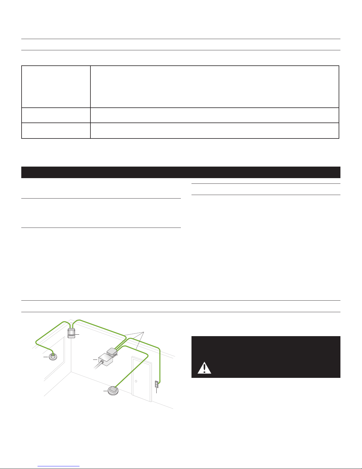
Détecteur de
Mouvement
en coin
Capteur
é
Boîte de
jonction
Vers
charge
Détecteur de présence
monté au plafond
Contrôleur
de pièce
EXEMPLE DE DISPOSITION
Réseau Local DLM
(câblage basse tension
Classe 2, câble LMRJ)
ATTENTION : POUR CONNECTER UN ORDINATEUR
AU RÉSEAU LOCAL DLM, UTILISER LE LMCI-100.
NE JAMAIS CONNECTER LE RÉSEAU LOCAL
Interrupteur
3
DLM À UN PORT ETHERNET – CELA
POURRAIT ENDOMMAGER LES ORDINATEURS
AINSI QUE LE MATÉRIEL CONNECTÉ.
 Loading...