

LEGRAND TradeMaster Installation Instructions Manual

INSTALLATION INSTRUCTIONS
TradeMaster
®
FAN SPEED CONTROLS
READ AND SAVE THESE INSTRUCTIONS!
To be installed by a certified electrician or other qualified person.
WARNING – To prevent severe shock or electrocution, always turn power OFF at
the service panel before installing this unit, working on the circuit, or changing a
lamp.
CAUTION – To reduce the risk of overheating and possible damage to
other equipment, do not install to control a receptacle, a fluorescent light,
or a transformer-supplied appliance. Use this control only with fans that are
marked as suitable for use with solid-state fan speed controls.
Any number of fans may be controlled by a single fan speed control provided
the sum amperage rating of the fans does not exceed the amperage rating of
the fan control.
Do not connect fan control to power source other than 120VAC, 60 Hz only.
Use copper wire only.
DIRECTIONS
1. Disconnect power to circuit at the panel by removing fuse or turning circuit
breakers OFF before installing.
2. Remove wall plate and switch mounting screws, pull existing switch from
wall box.
3. Disconnect existing switch from circuit.
4. Connect fan speed control as shown in the installation diagram using #12 or
#14 AWG stranded or solid copper conductors. Strip wire using gauge on
back of device.
5. Install fan speed control in wall box, with word ‘TOP’ on the strap right side
up, using mounting screws provided.
6. Restore power. To change the minimum speed DISCONNECT POWER
FROM CIRCUIT. Remove fan speed control from wall box. Use a small,
insulated, flat-tipped screwdriver to adjust trim pot located through access
opening on ground side of control. After adjusting, remount fan speed
control in wall box per above instructions. Restore power and test. Repeat
above as necessary. Disconnect power again when adjustment is complete.
NOTE: Never adjust trim pot when circuit is live.
7. Attach wall plate, then restore power to circuit.
NOTE: It is necessary to remove knob on Short Slide version before
attaching wall plate.
8. Attach wall plate.
NOTE: A 0.5A minimum load is required. It is normal for the control to feel
warm during operation. Use a separate neutral wire for each phase of a
multiphase system containing a dimmer, and for high power single phase
applications where flickering is present.
Toggle
FAN SPEED CONTROL TYPES
INSTALLATION DIAGRAM FOR SPEED CONTROLS (wiring is same with
each of the fan speed control types)
MULTIPLE GANGING OF DIMMERS & OTHER DEVICES
Any combination of fan control models and other devices may be ganged
together. Fan controls can be ganged without removing fins. De-rate the
maximum load according to the following table.
MAXIMUM
RATED LOAD
5A 4A 3A
WARRANTIES
Lifetime Warranty. The device you have purchased is warranted under normal
use against defects in workmanship and materials for as long as you own the
device. If the device fails due to manufacturing defect during normal use, return
the device for replacement to the store where purchased or send to:
All requests for replacement must include a dated sales receipt (legible copies
acceptable).
ALL OTHER WARRANTIES, INCLUDING BUT NOT LIMITED TO ANY
WARRANTIES OF MERCHANTABILITY OR FITNESS FOR A PARTICULAR
PURPOSE, ARE LIMITED TO A PERIOD OF TWO YEARS FROM THE
DATE OF PURCHASE. YOUR SOLE AND EXCLUSIVE REMEDY AGAINST
PASS & SEYMOUR LEGRAND UNDER ANY WARRANTY SHALL BE THE
EQUIVALENT REPLACEMENT OF THE DEVICE. IN NO EVENT SHALL ANY
WARRANTY APPLY TO ANY DEFECT ARISING OUT OF ANY ALTERATION
OF THE DEVICE, IMPROPER WIRING, IMPROPER INSTALLATION,
MISUSE, ABNORMAL USE OR NEGLIGENCE. IN NO EVENT SHALL PASS &
SEYMOUR LEGRAND BE LIABLE FOR LOST PROFITS, INDIRECT, SPECIAL,
EXEMPLARY, INCIDENTAL OR CONSEQUENTIAL DAMAGES. Some states
do not allow limitations on how long implied warranties last and do not allow
exclusion or limitation of incidental or consequential damages. Some of the
above limitations or exclusions may not apply to every purchaser.
GANG REDUCTION
2 CONTROLS 3+ CONTROLS
Pass & Seymour Legrand
50 Boyd Avenue
Syracuse, NY 13209
Decorator Slide
Short Slide
INSTRUCCIONES EN ESPA—OL
INSTRUCCIONES DE INSTALACIÓN
TradeMaster
MANDO DE VELOCIDAD DE VENTILADOR Y DOBLE MANDO
DE VELOCIDAD DE VENTILADOR/REDUCTOR DE LUZ
LEA Y GUARDE ESTAS INSTRUCCIONES
®
Para ser instalado por electricista certificado u otra persona capacitada.
ADVERTENCIA: Para prevenir una sacudida eléctrica severa o electrocución,
siempre CORTE la electricidad en el panel de servicio antes de instalar esta
unidad, trabajar en el circuito, o cambiar una lámpara.
AVISO: Para reducir el riesgo de recalentamiento y posiblemente dañar a
otro equipo, no instale para controlar un receptáculo, una luz fluorescente,
un artefacto alimentado por un transformador. Use este mando solo con
ventiladores que indican que son apropiados para uso con mandos de
velocidad de ventiladores de estado sólido.
Cualquier número de ventiladores pueden ser controlados por un solo mando
de velocidad de ventiladores dado que la suma de las tasas de amperaje de
los ventiladores no exija la tasa de amperaje del mando del ventilador.
No conecte al reductor de luz a otra fuente de potencia que no sea solo
120VAC, 60Hz.
Solo utilice cables de cobre.
INSTRUCCIONES:
1. Corte la electricidad al circuito en el panel quitando el fusible o
APAGANDO el interruptor automático antes de la instalación.
2. Quite la chapa de pared y los tornillos de montura de chucho, hale el
chucho existente de la caja embutida en la pared.
3. Desconecte el chucho existente del circuito.
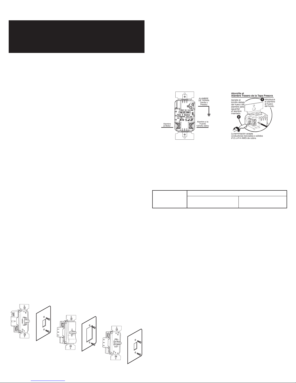
4. Conecte el controlador de velocidad del ventilador como mostrado en el
diagrama de instalación utilizando alambre trenzado o sólido #12 o #14
AWG de cobre. Pele el alambre utilizando la guÌa en la parte trasera del
aparato.
5. Instale el controlador de velocidad del ventilador en una caja de pared con
la palabra “TOP” en la correa hacia arriba, utilizando los tornillos de montaje
proveÌdos.
6. Restáurele la corriente al circuito. Para cambiarle la velocidad mÌnima
DESCONECTE LA CORRIENTE DEL CIRCUITO. Quite el controlador
de velocidad del ventilador de la caja de pared. Utilice un pequeño
destornillador plano aislado para ajustar el potenciómetro localizado
dentro del hueco de acceso en el lado de tierra del controlador. Después
de ajustar, monte el controlador de velocidad del ventilador en la caja de
pared de acuerdo con las instrucciones anteriores. Restaure la corriente y
pruebe. Repita lo anterior si es necesario. Desconecte la corriente otra vez
cuando el ajuste se termine. NOTA: Nunca ajuste el potenciometro cuando
el circuito está energizado.
7. Fije la chapa de pared, entonces restáurele la corriente al circuito. NOTA:
Es necesario quitarle la perilla en la versión de Deslice Corto antes de fijar
la chapa de pared.
8. Conecte la chapa de pared.
NOTA: Una carga mínima de 0.5A es requerida. Es normal que el mando se
sienta caliente durante su funcionamiento. Use un cable separado neutral
para cada fase de un sistema polifásico que tiene un reductor de luz, y para
aplicaciones de una fase de alta potencia donde ocurre centelleo.
TIPOS DE CONTROLADORES DE VELOCIDAD DE VENTILADORES
Volquete
ESQUEMA DE INSTALACIÓN DE CONTROLADORES DE VELOCIDAD DE
VENTILADORES (El alambrado es el mismo para cada tipo ???
AGRUPACIONES MÚLTIPLES DE REDUCTORES DE LUZ Y OTROS
APARATOS
Cualquier combinación de modelos de control de ventiladores u otros aparatos
pueden ser agrupados. Controles de ventiladores pueden ser agrupados sin
tener que remover los disipadores. Reduzca la capacidad máxima de acuerdo
con la siguiente tabla.
CAPACIDAD
MÁXIMA TASADA
5A 4A 3A
GARANTÍAS
Garantías de Por Vida: El aparato que Ud. ha comprado está garantizado
bajo uso normal contra de defectos de fábrica y materiales durante el tiempo
que Ud. posea el aparato. Si el aparato falla debido a defectos de fábrica
durante uso normal, devuelva el aparato para su reemplazo a la tienda
donde fue adquirido o envíelo a: Pass & Seymour Legrand, 50 Boyd Avenue,
Syracuse, NY 13209
Todos los pedidos de reemplazos deben incluir un recibo de compra fechado
(se aceptan copias legibles). TODAS LAS DEMÁS GARANTÍAS INCLUIDAS
PERO NO LIMITADAS A CUALQUIER GARANTÍA COMERCIAL O DE
PARTICULARIDAD PARA UN PROPÓSITO ADECUADO, ESTÁN LIMITADAS
A UN PERÍODO DE DOS A—OS A PARTIR DE LA FECHA DE COMPRA. SU
ÚNICO Y EXCLUSIVO DERECHO CON RESPECTO A PASS AND SEYMOUR
LEGRAND BAJO CUALQUIER GARANTÍA SERÁ EL REEMPLAZO POR
UN APARATO EQUIVALENTE. EN NINGÚN CASO, NINGUNA GARANTÍA
PODRÁ SER APLICADA A NINGÚN DEFECTO QUE SURJA DE NINGUNA
ALTERACIÓN DEL APARATO, CABLEADO IMPROPIO, INSTALACIÓN
IMPROPIA, MAL USO, USO ANORMAL O NEGLIGENCIA. BAJO NINGÚN
CASO, SERÁ RESPONSABLE PASS AND SEYMOUR LEGRAND DE DA—OS
POR PÉRDIDAS EN INGRESOS, INDIRECTOS, ESPECIALES, EJEMPLARES,
INCIDENTALES, O CONSECUENTES.
Algunos estados no permiten limitaciones en la duración de las garantías
implícitas y no permiten exclusión o limitación de daños accidentales o
consecuentes. Algunas de las limitaciones o exclusiones arriba enunciadas
podrán no ser aplicadas a cada comprador.
REDUCCIÓN DE AGRUPACIÓN
2 REDUCTORES DE LUZ 3+REDUCTORES DE LUZ
Deslice de Decoración
Deslice Corto
 Loading...