

Page 1
Source I
®
INSTALLATION INSTRUCTIONS
Installation Instruction No.: IB0001 R1 – Updated February 2007
Wiremold / Legrand electrical systems conform to and should be
properly grounded in compliance with requirements of the current
National Electrical Code or codes administered by local authorities.
All electrical products may present a possible shock or fire
hazard if improperly installed or used. Wiremold / Legrand electrical
products may bear the mark as UL Listed and/or Classified and should
be installed in conformance with current local and/or the National
Electrical Code.
IMPORTANT: Please read all instructions
before beginning.
Products Covered: 437, 439
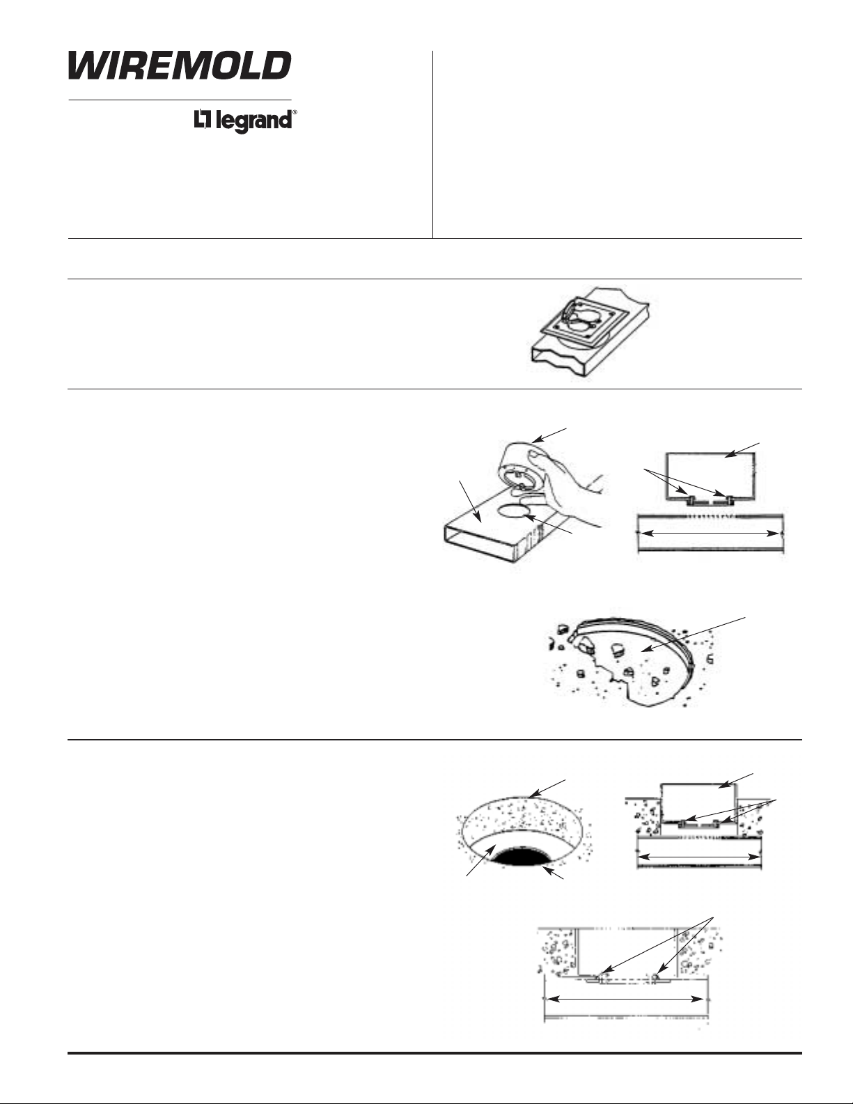
NOTE: Source I Fittings will run lengthwise on duct when
insert tabs are oriented toward the center as called
for in these instructions (see Figure 1).
AS A PRESET INSERT (437):
1. Install attaching ring in 2 1/2" [64mm] hole in raceway
before concrete is poured (see Figure A).
2. Hole can be factory prepunched or field drilled. Attaching
ring is secured by tightening locking tabs. Be sure the
locking tabs are oriented toward the center of the raceway
(see Figure B).
3. It is important that tabs on the attaching ring be properly
oriented on the duct so that activations will be aligned in
the desired direction. The mudcap should be securely in
place before the concrete pour. After the pour, chip away
concrete (see Figure C) and remove mudcap.
4. Go to Activation Instructions.
AS AN AFTERSET INSERT (437 or 439):
1. Establish location for the fitting, then core drill a 4" [102mm]
diameter hole in concrete (see Figure A). Do not drill
through the raceway.
2. Drill a 2 1/2" [64mm] diameter hole through the top of the
raceway (see Figure B). It should be located in the center of
the core drilled hole.
3. Install attaching ring on raceway making sure the locking
tabs are oriented toward the center of the raceway (see
Figure C). It is important that tabs on the attaching ring be
properly oriented so that activations will be aligned.
4. Go to Activation Instructions.
Figure 1
Figure A
Figure B
Figure C
Attaching Ring
2 1/2" [64mm]
Hole
Walkerduct
Attaching Ring
Duct Direction
Locking
Tabs
Mudcap
Figure A
Figure B
Figure C
4" [102mm]
Hole
2 1/2" [64mm]
Hole
Duct
Attaching Ring
Duct Direction
Locking
Tabs
Tabs Outward
Duct Direction
Page 2
Wiremold / Legrand
U.S. and International:
60 Woodlawn Street • West Hartford, CT 06110
1-800-621-0049 • FAX 860-232-2062 • Outside U.S.: 860-233-6251
Canada:
570 Applewood Crescent • Vaughan, Ontario L4K 4B4
1-800-723-5175 • FAX 905-738-9721
1B0001 R1 0207
© Copyright 2007 Wiremold / Legrand All Rights Reserved
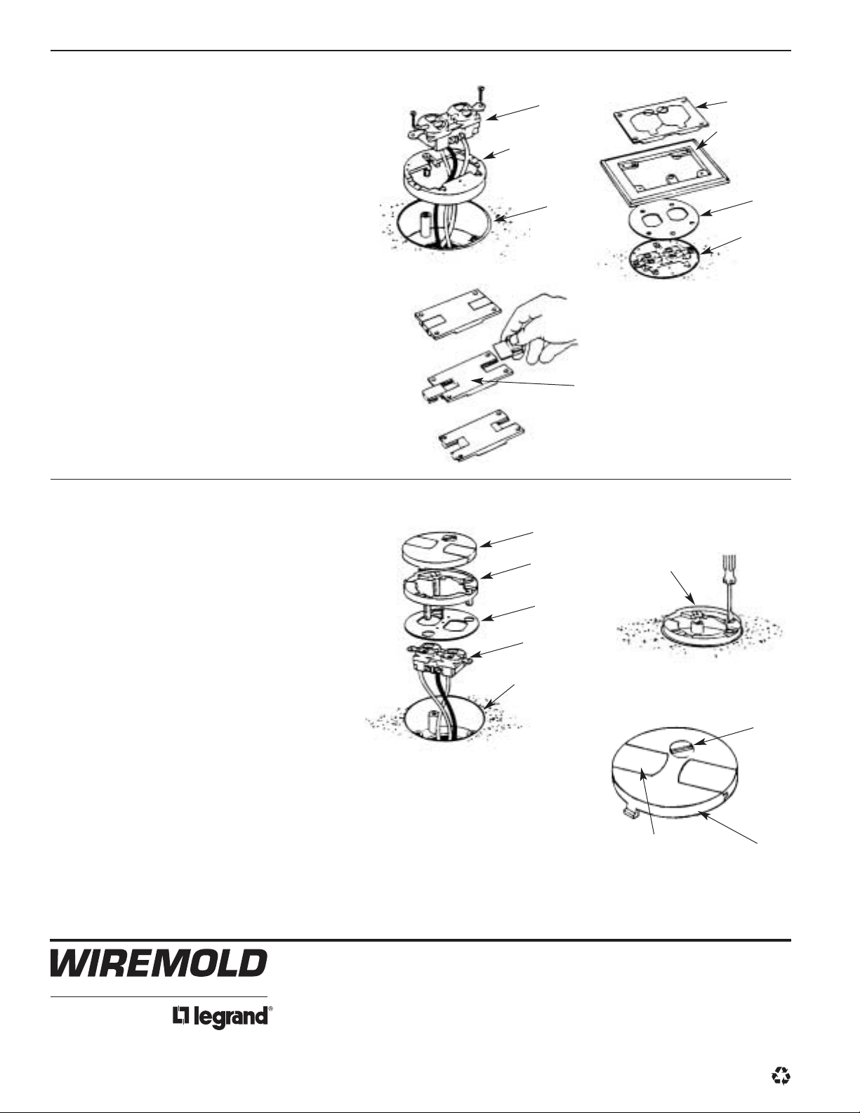
1. Pull wires through the hole in the bottom of the
attaching ring. The adjusting ring should then
be installed at the desired height.
2. Wire device and attach to the adjusting ring
(see Figure A).
3. After the gasket is put in place, the flange is
attached to the adjusting ring (see Figure B).
4. For power: The flip lid cover plate can be
attached to the flange (see Figure B).
5. For data: Turn slides upside down with thin
edge to inside. Attach cover plate to flange
(see Figure C).
FLUSH ACTIVATION:
1. Pull wires through the hole in the bottom of the
attaching ring.
2. Wire device and attach to threaded bosses in
bottom of attaching ring. Fasten receptacle
cover plate to device (see Figure A).
3. Install adjusting ring at desired height (see
Figure B).
4. Cover plate can be locked in place with quarter
turn swivel (see Figure C).
RECESSED ACTIVATION (S126R):
Walkerduct
Figure A
Figure C
Figure B
Wiring Device
437 Attaching Ring
Adjusting Ring
897AR for Power
(Shown) 898AR
for Tele/Data
Power Cover
Plate – S125B
Neoprene Gasket
Adjusting Ring
Assembly
Carpet Plate
S124B (Shown) or
S124BLK/BRN
Tele/Data Cover Plate
NOTE: Minimum 2 3/8" [60mm] Attaching
Ring required.
Walkerduct
Figure A
Figure C
Figure B
Cover Plate
Closure Plate
Wiring Device
Attaching Ring
437
Adjusting Ring
Swivel Lock
Adjusting Ring
Reversible Slides
Cover Plate
 Loading...