

Page 1
Integrated 5-Scene Preset Dimming System
INSTALLATION & OPERATING INSTRUCTIONS
Part No. 340542 Rev. B 85-1209
Important: Retain These Instructions For The End User.
DO NOT THROW AWAY!
For Use with Models: SCMC5, SC600, SCELV600, SCFB600,
SCDH15, SCR, SCIR, SCMCK
ESCRIPTION
D
Pass & Seymour Scene Control products are a
revolutionary system of advanced digital wallbox
dimmers for economical and flexible multi-scene, multichannel control. They provide flexible 5-scene preset
dimming control of up to 30 devices as well as 12
adjustable fade rates up to one hour that are
programmable by scene.
CAUTION
Be sure that power to the load being controlled has been
disconnected by removing fuse or turning circuit breaker
off. Installing these products with power on may expose
you to dangerous voltage and/or damage the device.
READ BEFORE BEGINNING INSTALLATION
1. All devices require a neutral connection. Each circuit feeding dimmers and
dimmed loads requires a separate neutral. Shared neutrals will result in
undesirable flashing of controlled loads.
2. Use Electronic Low Voltage dimmers to control only low-voltage fixtures
that have electronic, solid-state transformers or regular incandescent loads.
3. Use Fluorescent Ballast Dimmers to control Advance Mark X®Dimmable
Electronic Ballast.
4. Dimmers may be fed individually or in groups, regardless of phase.
5. Masters draw approximately one watt and may be fed from any circuit.
Multiple masters may be inter-connected. The total number of dimmers and
masters are not to exceed 30. An unlimited number of channel remotes
(SCR) may be used.
6. Line voltage must not be supplied by a GFI breaker.
INSTALLATION INSTRUCTIONS – DIMMERS
CAUTION: Be Sure that power is disconnected to avoid damage to unit and
shock hazard to installer.
1. If you are replacing an existing device with a Dimmer or Remote:
A. Remove faceplate from existing device.
B. Unscrew and pull device out of wallbox.
C. Disconnect wires from device. Identify and mark the "hot", "load" and
traveler wires connected to the device.
2. Be sure Dimmer is in "System Off" position by firmly pressing bottom of
device until it snaps into place and the "System Off" label at the top of
device is exposed.
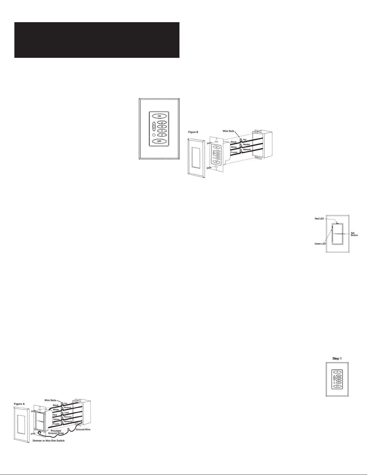
3. Connect the Dimmer wires to the Wallbox wires as follows:
A. Black to Hot (120V AC Source)
B. White to Neutral*
C. Red to Load (Light Fixture)
D. Yellow to Remote (SCR). Cap yellow if SCR is not used.
E. Purple to Network Connection (Line Voltage Class 1)**
4. Be sure the Ground wire (bare stranded) is connected to earth ground.
Note: Miswiring or failure to connect ground may result in improper
operation of the device.
5. Ensure all wire connectors are tight and completely cover copper wire,
(except ground).
6. Install device into wallbox, making sure that all wires are neatly installed
into wallbox. Using mounting screws provided, secure device into wallbox.
7. Install faceplate.
* The White wire must be connected to the
neutral wire in the wallbox. Failure to
connect the White wire to the neutral will
result in improper operation.
** Link all devices using one line voltage
wire connected between each Purple
wire. Connected devices will operate as
a system.
INSTALLATION INSTRUCTIONS – MASTERS (SCMC5)
1. Caution: Be sure that power is disconnected to avoid damage to unit and
shock hazard to installer.
2. Connect Master wires to the Wallbox wires as follows (Figure B):
A. Black to Hot (120V AC Source)
B. White to Neutral*
C. Purple to Network Connection (Line Voltage Class 1)**
3. Ensure all wire connectors are tight and completely cover copper wire.
4. Install device into wallbox, making sure that all wires are neatly installed
into wallbox. Using mounting screws provided, secure Master into wallbox.
5. Install faceplate.
* The White wire must be connected
o the neutral wire in the wallbox.
t
Failure to connect the White wire to
he neutral will result in improper
t
operation.
** Link all devices using one line
oltage wire connected between
v
each Purple wire. Connected
evices will operate as a system.
d
DIMMER OPERATING INSTRUCTIONS
1. To turn light on to preset level tap top of rocker. The dimmer will fade up
at the 1.5 second rate.
2. A second tap of the rocker fades the dimmer to full brightness.
3. To adjust the light level, press and hold top or bottom
of rocker until desired light level is reached, and then
release. Ramping will be at the 3 second rate.
4. To turn lights off, tap the bottom of the rocker. The
dimmer will fade at the 3 second fade rate.
5. To quickly return to the preset level when light is on,
quickly tap OFF and then ON. The lights will then
adjust to the preset level.
6. To bypass the fade rate and turn the lights to full ON or OFF, double tap
the dimmer for ON or OFF.
7. If the master is in the OFF scene, the master ON button will illuminate
when any dimmer is turned on.
8. To change the preset level of the current scene:
• Press and hold the rocker until lights reach the desired level then release
• Press the set button to save the preset in memory
LEDs on the Dimmers indicate status:
1. Red LED is on when Dimmer is off to locate Dimmer when room is dark.
2. As many as 3 green LEDs may be illuminated at any given time. The bright
green LED indicates the current level of the dimmer. The medium green
LED indicates the preset level of the current scene. The dim green LED
indicates the preset level of the ON scene.
PROGRAMMING AND OPERATING THE SCENE MASTER
After you have completed installation of all of the devices and have energized
the system, programming of each scene can be performed. Programming is
as simple as 1, 2, 3!
1. Tap the preset button (ON, A – D) on the Master Controller
that you wish to program.
2. Adjust each Dimmer to the desired intensity.
3. Press the Set button on each device (See step 8 in prior
section) after all devices have been adjusted.
Repeat Steps 1-3 until all scenes have been programmed.
* Note: Dimmers cannot be programmed off for the
“ON” preset.
Page 2
PERATING INSTRUCTIONS
On
Relax
E
ntertain
Dinner
Breakfast
O
ff
On
Night
E
vening
Daytime
Morning
O
ff
White
Bare
Black
G
round
Black
Purple
Black
White Purple
Black
White Purple
To Load
Red
Yellow
Bare
G
round
Gray
Hot (Black)
Neutral (White)
Communication Wire
D
immers*
SC600
SCELV300
SCFB600
SCDH15
SCR
(attach yellow wires if
remote control of a single
load is desired)
SCMC5
More than one Master can
be used to control entire scenes
from multiple locations.
Scene Controllers
*
Add additional dimmers as needed to control more loads. Use same wiring practices as dimmer shown above.
O
• Press or Tap the ON button to elegantly illuminate the entire area to the ON
"preset". The ON scene will ramp up at the 1.5 second rate.
• Press and hold the RAISE/LOWER button to brighten/dim
lighting level.
• Press or Tap the OFF button to fade lights to OFF.
• Tap a scene button to access one of the "preset" light
levels.
• Two quick taps of any button (except RAISE or
LOWER) will fade the lighting quickly.
• For information on the IR Receiver, see the Accessories section.
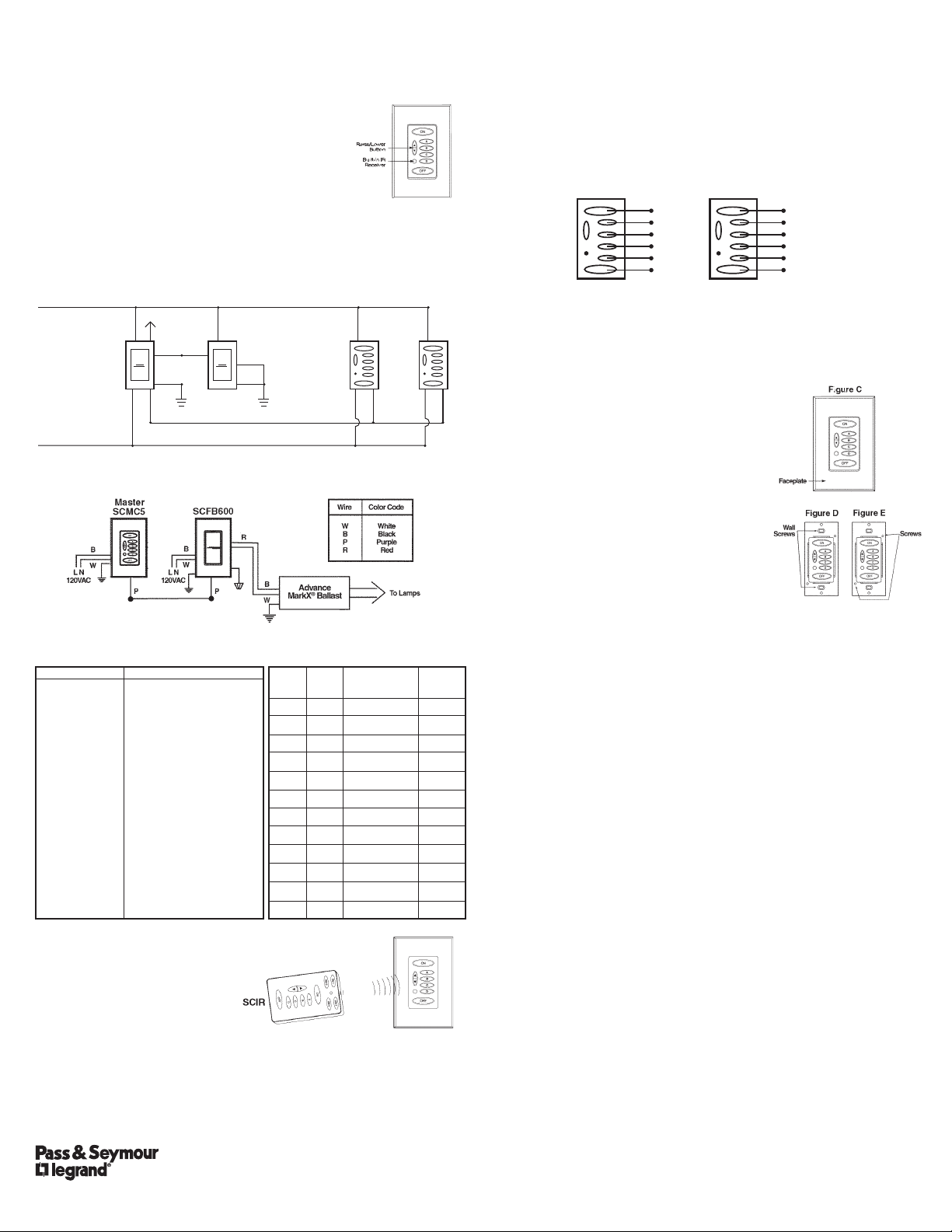
IRING DIAGRAM
W
DIRECT DRIVE FLUORESCENT DIMMING (FB DIMMER)
TROUBLESHOOTING GUIDE TOTAL BALLAST QUANTITY
FOR SCFB600
Sympton
Lamps do not start,
flicker or go out at
low-level
One lamp end
repeatedly
blackens
prematurely
Possible Solution
• Linear lamps are particularly
sensitive to the correct
grounding of the ballast to
the fixture. Verify proper
ground wire installation.
• Control device minimum set
point adjusted too low.
Try raising slightly.
• Lamps not seated properly in
lamp sockets. Reseat lamps.
• To ensure control is operating
properly, connect an
incandescent lamp load
across the red dimming wire
and white neutral wire at the
wallbox. Control should dim
the lamp properly.
• Possible loose, shorted or
broken wires between lamp
and ballast. Verify wiring is
correct and not damaged.
Lamp
Watts
26
32
42
26
40
40
25
25
25
32
32
32
Type
Lamp
T4
T4
T4
T4
T5
T5
T8
T8
T8
T8
T8
T8
Ballast
Model
REZ–IT32
REZ–IT32
REZ–IT42
REZ–2Q26
REZ–ITT540
REZ–2TT540
REZ–132
REZ–2532
REZ–3532
REZ–132
REZ–2532
REZ–3532
ACCESSORIES & OPTIONS
Infrared Remote
The SCMC5 Master has an integrated
infrared (IR) receiver that allows it to
receive IR commands from a remote
control unit (SCIR).
The SCIR infrared transmitter is capable of operating over an unobstructed
range of approximately 25 feet. Within this range, scenes can be selected,
raised and lowered, and lighting may be turned On and Off using the
handheld remote transmitter. In addition, the SCIR is capable of controlling
up to 4 different groups within a building. A Group here is defined as all
dimmers and master control units that are connected by the same (purple)
control wire.
P.O. Box 4822, Syracuse, NY 13221 www.passandseymour.com Technical Support (800) 223-4185
No. of
Ballast
19
15
12
10
15
7
19
10
6
15
8
5
NOTE: This system is based on line-of-sight operations. Therefore, the
receiver must be able to “See” the transmitter. Any obstruction between the
transmitter and receiver will adversely affect the performance of the unit.
Replacement Keypads
Replacement keypads are available for the SCMC5 with specific
descriptions for lighting scenes. The following two keypads are prescribed
with times of the day and events of the day, which help define your scenes
more clearly. They can be ordered using catalog number: SCMCK. Contact
your local Pass & Seymour dealer.
The lighting load fade rate and the master control button brightness are
both adjustable. Contact our Technical Applications group for further
instructions. (1-800-223-4185)
REPLACING THE KEYPAD MEMBRANE
The overlay on these models is easily replaced, even if the unit is currently
installed.
1. Turn the power off at the circuit breaker.
2. Remove the faceplate (Figure C).
3. Remove the master keypad wall screws
(Figure D).
4. Remove the retaining plate screws and plate
(Figure E).
5. Remove the existing keypad membrane.
6. Install the new keypad membrane, being
careful to line it up properly with the
openings.
7. Reinstall the retaining plate screws
(Figure E).
8. Reinstall the master keypad to wallbox
(Figure D).
9. Reinstall the faceplate (Figure C).
10. Turn the power back on at the circuit breaker.
LIMITED THREE YEAR WARRANTY
Pass & Seymour will remedy any defect in workmanship or material in Pass & Seymour
products which may develop under proper and normal use within three years from date
of purchase by a consumer:
(1) by repair or replacement, or, at Pass & Seymour's option, (2) by return of an amount
equal to consumer's purchase price. Such remedy is IN LIEU OF ANY AND ALL
EXPRESSED OR IMPLIED WARRANTIES OF MERCHANTABILITY OR FITNESS FOR A
PARTICULAR PURPOSE. Such remedy by Pass & Seymour does not include or cover
cost of labor for removal or reinstallation of the product. ALL OTHER FURTHER
ELEMENTS OF DAMAGE (INCIDENTAL OR CONSEQUENTIAL DAMAGES) FOR
BREACH OF ANY AND ALL EXPRESSED OR IMPLIED WARRANTIES INCLUDING
WARRANTIES OF MERCHANTABILITY OR FITNESS FOR A PARTICULAR PURPOSE
ARE EXCLUDED HEREBY. (Some states do not allow disclaimers or exclusion or
limitation of incidental or consequential damages, so the above disclaimer and limitation
or exclusion may not apply to you.) ANY IMPLIED WARRANTIES INCLUDING WHERE
REQUIRED WARRANTIES OF MERCHANTABILITY OR FITNESS FOR A PARTICULAR
PURPOSE SHALL BE LIMITED TO THE THREE YEARS PERIOD SET FORTH ABOVE.
(Some states do not allow limitations on how long an implied warranty lasts, so the
above limitation may not apply to you.)
To insure safety, all repairs to Pass & Seymour products must be made by Pass &
Seymour, or under its specific direction. Procedure to obtain performance of any
warranty obligation is as follows: (1) Contact Pass & Seymour, Syracuse, New York
13221, for instructions concerning return or repair; (2) return the product to Pass &
Seymour, postage paid, with your name and address and a written description of the
installation or use of the Pass & Seymour product, and the observed defects or failure to
operate, or other claimed basis for dissatisfaction.
This warranty gives you specific legal rights and you may also have other rights which
vary from state to state.
This product may be covered by one or more of the following U.S. Patents:
#4,413,211; 4,430,576; 4,465,956; 4,733,138; 4,792,731; 4,880,950; 4,988,840;
4,992,709; 5,128,654; 5,153,816; 5,189,259; 5,194,858; 5,371,439; 5,371,444;
5,636,111; 5,642,104; 5,646,490; 5,920,156; Des. 307,578; Des. 333,124; License
4,482,844 and corresponding foreign patents. Other Utility, Design and Foreign Patents
Pending.
We reserve the right to change details of design, materials and finish, in any way that
will not alter installed appearance or reduce function performance.
 Loading...