

Page 1
SAF21/2
Legrand/Wiremold electrical systems conform to and should be properly
grounded in compliance with requirements of the current National
Electrical Code or codes administered by local authorities.
All electrical products may present a possible shock or fire
hazard if improperly installed or used. Legrand/Wiremold electrical
products may bear the mark of a Nationally Recognized Testing
Laboratory (NRTL) and should be installed in conformance with current
local and/or the National Electrical Code.
Raised Floor Box
I N S T A L L A T I O N I N S T R U C T I O N S
Installation Instruction No.: 1 002 430R3 – Updated January 2011
IMPORTANT: Please read all instructions
before beginning.
PRODUCTS COVERED: SAF21/2
NOTE: Products are suitable for use in air handling spaces in accordance with Sec. 300-22(C) of the National Electrical Code.
CAUTION: Flange is an integral part of the box assembly. DO NOT REMOVE.
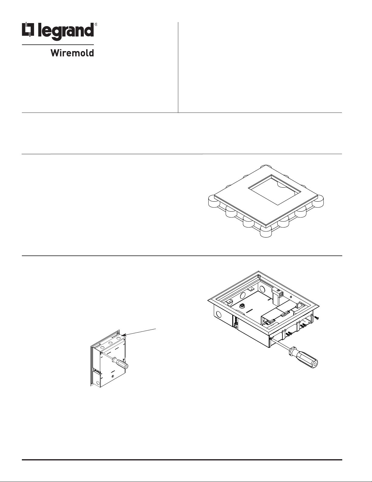
Step 1 Cut or form an 8 1/16" x 10 1/8" [205mm x
257mm] (+ 1/16" - 0") opening in the raised
floor panel and carpet. (See Fig. 1.)
FIG. 1
Step 2 Blank communication plates come standard in floor box.
If other communication plates are required, remove
communication conduit plate. (See fig 2.) Remove only
blank communication plates that need exchanged and
attach new communication plates (sold separately) to
the floor box using (2) #8-32 x 3/8" self-tapping
screws provided. (See fig 3.) Reattach communication
compartment cover. ( See fig 2.)
FIG. 2
NOTE: Communication conduit plate
required only if using conduit to supply
communications cabling. (See Step 5.)
Communication
Conduit Plate
FIG. 3
Page 2
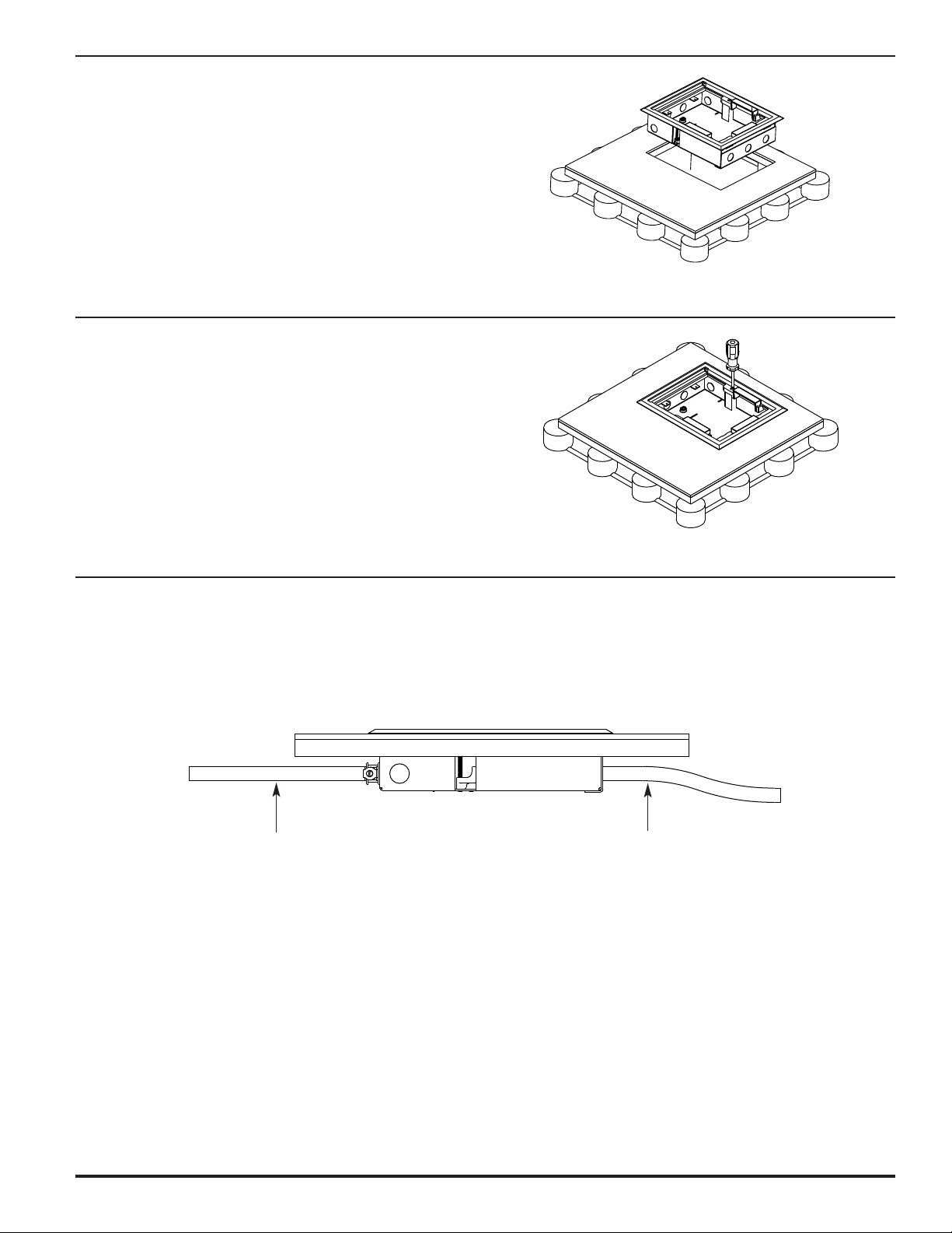
Step 3 Place Walker Shallow Raised Floor Box in
opening created in step one.
(See Fig. 4.)
CAUTION: Flange is an integral part of the box
assembly. DO NOT REMOVE.
Separating the Flange from the Box
may cause damage to the Flange and
Box, prevent reattachment, and may
also cause the Box to not sit properly
in the opening.
Step 4 Using a Phillips screwdriver tighten the (2)
#10-24 X 2 1/4" locking tab screws on
both sides of the floor box.
(See Fig. 5.)
Step 5 Remove appropriate knockout(s) and feed
flexible conduit to the floor box. Pull wires
into the box and connect conduit to the
box with a conduit connector. Pull
communication wires into box.
(See Fig. 6.)
FIG. 4
FIG. 5
FIG. 6
Power Conduit,
not supplied by
Walker Systems, Inc.
NOTE: The communication conduit plate does not need to be attached behind
a compartment used for low voltage. Where required by local codes,
connect conduit to the communication conduit plate. Type CMP
communications plenum cable is required in raised floor plenums when
wiring methods as described in NEC Article 300-22 are not followed.
Communication Cables,
not provided by
Walker Systems, Inc.
Page 3

Step 6 Attach electrical conductors to the UL Listed
duplex receptacles (provided by others).
Make sure that any ground leads are
connected to ground screws.
See Fig. 7.)
(
Step 7 Attach insulator and faceplate to receptacle
using one #6-32 x 3/8" screw provided. Attach
the receptacle to the receptacle mounting bracket
with two additional screws and nuts (Provided).
(See Fig. 8.) Make sure receptacle ground lug
faces toward inside of floor box. (See Fig. 9.)
FIG. 7
Insulator
Step 8 Make sure receptacles are oriented the same as in
Fig. 9. Neatly compress wires into compartment
and push the face plate back into the box until
the tabs on the bottom of the face plate engage
the slots in the bottom of the box. Attach the
face plate to the mounting tabs of the box
using (1) #8-32 x 3/8" screw provided.
(See Fig. 9.)
#6-32
Hex Nut
FIG. 8
Proper Receptacle
Orientation
FIG. 9
Engage tabs
into slots.
Page 4

Step 9 Make necessary connections to specified
ommunication jacks (Not supplied). Snap
c
the supplied bezel into opening followed
by the device. (See Fig. 10.)
NOTE: Low voltage cables may be pulled through
a bushing in one of the communication
device plates or may be attached to a
device that is mounted to the plate.
Step 10 When the box is not in service, the wire
retainer should be installed (textured side
up) to block off the cable exit. (See Fig. 11.)
Otherwise, any exiting cables should be
routed through the wire retainer prior to
closing the lid. (See Fig. 12.)
FIG. 10
Textured Surface
FIG. 11
Step 11 For carpet installations use the 8 1/16" x 10 1/8"
[205mm x 257mm] carpet blank remaining from
the opening and cut a piece to match the recess
in the cover. Glue the piece of carpet onto the
floor box cover. (See Fig. 13.)
NOTE: The Walker Shallow Raised Floor Box should
be used on access floor installations.
Do not use in concrete or wood floors.
FIG. 12
Carpet
FIG. 13
© Copyright 2011 Legrand/Wiremold All Rights Reserved
WIREMOLD
U.S. and International:
60 Woodlawn Street • West Hartford, CT 06110
1-800-621-0049 • FAX 860-232-2062 • Outside U.S.: 860-233-6251
Canada:
570 Applewood Crescent • Vaughan, Ontario L4K 4B4
1-800-723-5175 • FAX 905-738-9721
1 002 430R3 0111
 Loading...