

Page 1
Source I
®
Double Duplex Power Activation
Cat. No. S175BLK/BRN
INSTALLATION INSTRUCTIONS
Walker® electrical systems conform to and
should be properly grounded in compliance
with requirements of the current National Code
or codes administered by local authorities.
All electrical products may present a possible
shock or fire hazard if improperly installed or
used.Walker electrical products may bear the
mark as UL listed and/or classified and should
be installed in conformance with current local
and/or the National Electrical Code.
1. Locate center of duct runs using measurements from insert markers. Determine
location of activation fitting, then core
drill a 4" [102mm] diameter hole through
the concrete to the top of the duct.
Do not drill through the raceway metal.
2. Drill 2 1/2" [64mm] diameter hole in
duct concentric with the center of the
4" [102mm] diameter hole in the concrete.
3. Install attaching ring (Cat. No. 439) using
the two locking tabs to secure it to the
duct. Locking tabs are to be secured
to the left and right sides of the duct.
4. Attach the carpet flange to the attaching
ring with four #6-32 flat head screws provided (length of screws are determined
by depth of concrete over duct).
5. Pull wires through opening in bottom
of attaching ring and wire devices in
accordance with the National Electrical
Code and any local code that applies.
6. Secure devices to carpet flange using
screws provided (orient receptacles
with neutral sides facing one another).
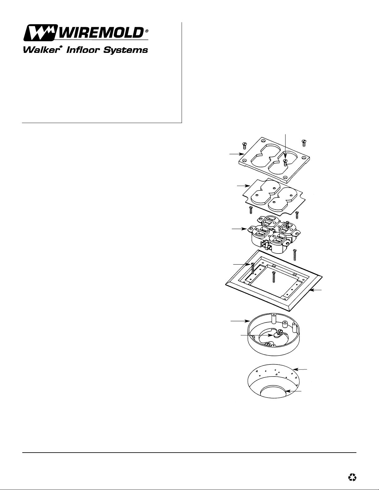
7. Place receptacle membrane over
receptacles and attach receptacle
plate to carpet flange with four flat
head self threading screws.
Receptacle Plate
Self Threading Screws
Receptacle Membrane
15 amp –
125V Receptacle
#6-32 x 2" [51mm] Screws
Carpet Flange
Attaching Ring
(Cat. No. 439)
Locking Tab
4" [102mm] Dia. Hole
2 1/2" [64mm] Dia. Hole
Walker Systems, Inc.
1000 Innovation Drive, Williamstown, WV 26187
IB0004 0300
© Copyright 2000 The Wiremold Company All Rights Reserved
 Loading...