

Page 1

TROUBLESHOOTING
To test the time switch:
The pilot light behind the ON/OFF button and time delay indicator light should
be ON when the switch is OFF. Press the ON/OFF button. The connected light or
fan comes ON. The pilot light behind the ON/OFF button turns OFF.
The connected light or fan should turn OFF in the number of minutes indicated
by the time selection indicator light. You can turn it OFF sooner by pressing the
ON/OFF button again.
Light or fan will not turn ON (pilot light is visible):
Press ON/OFF button. The connected light or fan should turn ON. If not:
• Check the light bulb and/or motor switch on the fan mechanism.
• Turn OFF power to the circuit then check wire connections.
Light or fan will not turn ON (no pilot light or indicator is visible):
• Shade the switch from external light to make sure that none of the indicator
lights on the switch are ON.
• Check the light bulb and/or motor switch on the fan mechanism.
• Make certain that the circuit breaker is ON and functioning.
• Turn OFF power to the circuit then check wire connections.
• Call 1.800.223.4185 for technical support.
Light or fan will not turn OFF:
• Press the ON/OFF button. If connected light or fan does not turn OFF, turn
OFF power to the circuit then check wire connections.
Visit our website at: www.passandseymour.com
340792RevB_Eng:NEW 10/23/08 10:54 AM Page 2
Page 2

Limited FIVE YEAR Warranty
Pass & Seymour/Legrand will remedy any defect in workmanship or material in Pass & Seymour/Legrand products
which may develop under proper and normal use within five years from the date of purchase by a consumer:
(1) by repair or replacement, or, at Pass & Seymour/Legrand’s option, (2) by return of an amount equal to the
consumer’s purchase price. Such remedy is IN LIEU OF ANY AND ALL EXPRESSED OR IMPLIED WARRANTIES OF
MERCHANTABILITY OR FITNESS FOR A PARTICULAR PURPOSE. Such remedy by Pass & Seymour/Legrand does not
include or cover cost of labor for removal or reinstallation of the product. ALL OTHER FURTHER ELEMENTS OF
DAMAGE (INCIDENTAL OR CONSEQUENTIAL DAMAGES) FOR BREACH OF ANY AND ALL EXPRESSED OR IMPLIED
WARRANTIES INCLUDING WARRANTIES OF MERCHANTABILITY OR FITNESS FOR A PARTICULAR PURPOSE ARE
EXCLUDED HEREBY. (Some states do not allow disclaimer or exclusion or limitation of incidental or consequential
damages, so the above disclaimers and limitation or exclusion may not apply to you.) ANY IMPLIED WARRANTIES
INCLUDING WHERE REQUIRED WARRANTIES OF MERCHANTABILITY OR FITNESS FOR A PARTICULAR PURPOSE
SHALL BE LIMITED TO THE FIVE YEAR PERIOD SET FORTH ABOVE. (Some states do not allow limitation on how long
an implied warranty lasts, so the above limitation may not apply to you.)
To ensure safety, all repairs to Pass & Seymour/Legrand products must be made by Pass & Seymour/Legrand or
under its specific direction. Procedure to obtain performance of any warranty obligation is as follows: (1) Contact
Pass & Seymour/ Legrand, P.O. Box 4822, Syracuse, NY 13221 for instructions concerning return or repair; (2) return
the product to Pass & Seymour/Legrand, postage paid, with your name and address and a written description of the
installation or use of the Pass & Seymour/Legrand product, and the observed defects or failure to operate, or other
claimed basis for dissatisfaction.
This warranty gives you specific legal rights and you may also have other rights which vary from state to state.
P.O. Box 4822, Syracuse, NY 13221-4822
Technical Support: 800.223.4185 • www.passandseymour.com
340792 Rev. B 07943
340792RevB_Eng:NEW 10/23/08 10:54 AM Page 3
Page 3
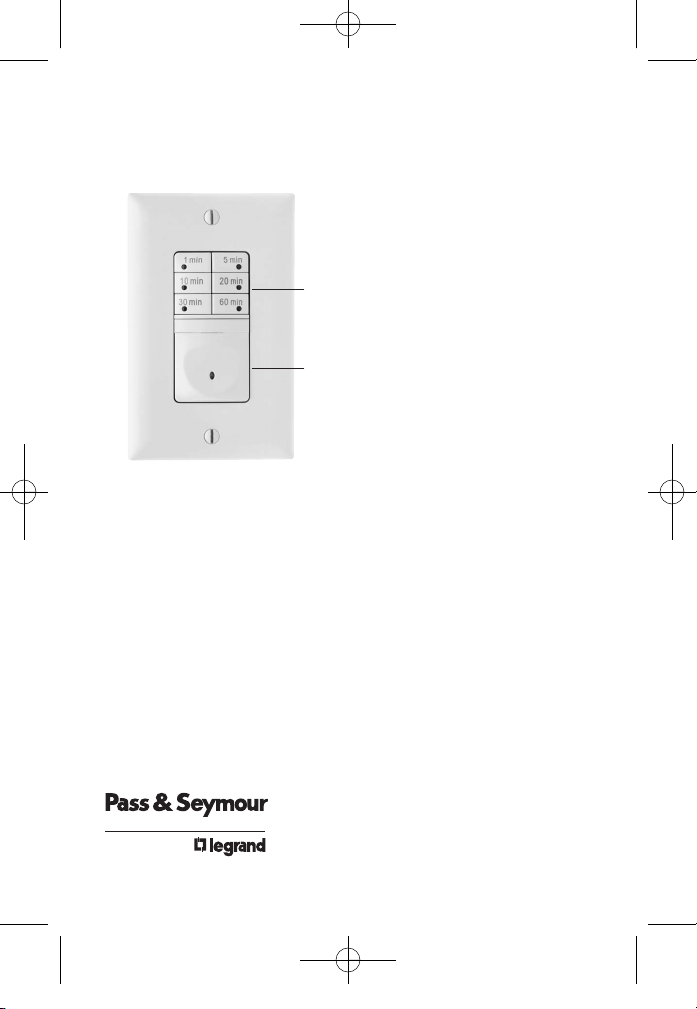
RT1
Time Switch
7-Button Preset
Installation Instructions
SPECIFICATIONS
Voltage . . . . . . . . . . . . . . . . . . . . . . . . . . . . . . . .120VAC, 60HZ
Load
Single Pole Circuit . . . . . . . . . . . . . . . . . . . . . 0 – 600 Watt
Incandescent or fluorescent lamp or 1/6HP fan motor
Time Delay . . . . . . . . . . . . . . . . . . .1, 5, 10, 20, 30, 60 minutes
Environment
Operating Temperature . . . . . . . .32° to 131°F (0° to 55°C)
Humidity . . . . . . . . . . . . . . . . . . . .95% RH, non-condensing
Tools Needed
Insulated Screwdriver
Wire Strippers
Please read all instructions before installing
6 time selection buttons with
activation indicator lights
ON/OFF button with pilot light
340792RevB_Eng:NEW 10/23/08 10:54 AM Page 4
Page 4

DESCRIPTION AND OPERATION
The RT1 is a time switch that turns OFF the connected light or fan when the
selected time expires. The pilot light behind the ON/OFF button and the time
delay indicator light illuminates while the switch is OFF. When the switch is ON,
the pilot light behind the ON/OFF button turns OFF.
Manual ON
Turn ON the connected light or fan by pressing the desired time button, or the
ON/OFF button. If you press the ON/OFF button, it activates the time delay that
was last used.
Manual OFF
While the timer is active, you can press the ON/OFF button to turn OFF the
connected light or fan without delay.
Changing the selected time
If you decide that you need more or less time than you originally selected,
restart the time switch by pressing the button that matches the amount of time
you think you’ll need.
Call 800.223.4185 for Technical Support
340792RevB_Eng:NEW 10/23/08 10:54 AM Page 5
Page 5
INSTALLATION & WIRING
1. Prepare the switch box.
After the power is turned OFF at the circuit
breaker box, remove the existing wall plate and
mounting screws. Pull the old switch out from the
wall box.
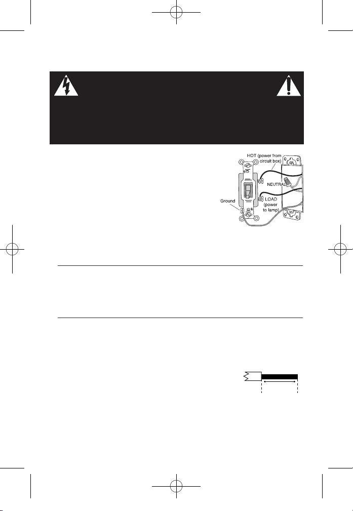
2. Identify the type of circuit.
In a Single Pole Circuit (see Fig. 2), two single
wires connect to two screws on the existing
switch. A ground wire may also be present and
connected to a ground terminal on the old switch.
A neutral wire should also be present in the
wall box.
CAUTION
For your safety: Connecting a proper ground to the time switch provides
protection against electrical shock in the event of certain fault conditions.
If a proper ground is not available, consult with a qualified
electrician before continuing installation.
Only connect the RT1 to a Single Pole Circuit. The RT1 is not suitable for
3-way switching. If the existing wiring does not match the description for a
Single Pole Circuit, you should consult with a qualified electrician.
3. Prepare the wires.
Tag the wires currently connected to the existing switch,
so that they can be identified later. Disconnect the wires.
Make sure the insulation is stripped off the wires to
expose their copper cores to the length indicated by the
“Strip Gage” in Fig. 3 (approximately 1/2 inch).
Visit our website at: www.passandseymour.com
Strip Gage
1/2"
12.7mm
Fig 3: Wire Stripping
WARNING
Disconnect power to the wall switch box by turning OFF the circuit
breaker or removing the fuse for the circuit before installing the
RT1, replacing lamps, or doing any electrical work.
Fig 2: Typical Single Pole
Switch Wiring
340792RevB_Eng:NEW 10/23/08 10:54 AM Page 6
Page 6
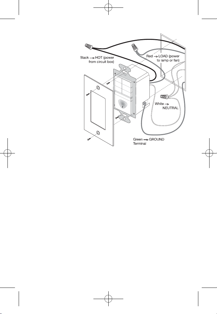
4. Wire the time switch.
Twist the existing
wires together with
the wire leads on
the time switch as
indicated in the
drawing. Cap them
securely using the
wire nuts provided.
See Fig 4.
• Connect the green
or non-insulated
(copper) GROUND
wire from the circuit
to the GROUND
terminal on the RT1.
• Connect the power
wire from the circuit
(HOT) to the black
wire on the RT1.
• Connect the power
wire to the lamp or fan
(LOAD) to the red wire
on the RT1.
• Connect the NEUTRAL wires from the circuit to the white wire on the RT1.
5. Put the RT1 in the wall box with the time selection buttons
positioned above the ON/OFF button.
Secure it to the wall box with the screws provided.
6. Attach the new cover plate.
7. Restore power to the circuit.
Turn on the breaker or replace the fuse.
Fig 4: Switch Orientation, Wire Connections and
Wall Box Assembly
340792RevB_Eng:NEW 10/23/08 10:54 AM Page 7
Page 7
REV. DESCRIPTION INT: REV.DATE APPROVED
1 ECO# C01610 MJS
• Print: 2-sided
• Ink Color: Black
• Paper: White 16lb (60g/m sq)
• Final trim size: 12" (Wide) x 6" (High).
• Three (3) fold.
• Final folded size: 4" (Wide) x 6" (High).
TITLE BOX PAGE ONLY.
DO NOT
MAKE FILM • DO NOT PRINT
SYRACUSE, NEW YORK
Title:
RT1 Installation Instructions
IF YOU HAVE ANY QUESTIONS REGARDING SPECIFICATIONS OR REQUIRE
ADDITIONAL FILE FORMATTING, PLEASE CONTACT Joyce Rougeau.
Phone: 315.437.7561
Email: jrougeau@aggraphics.com
Drawing
#:
Orig. Drawing Date: 29
Rev. #:
1
Revision Date:
ROUGEAU
Scale: 1:1
All information in this drawing is the property of P&S/Legrand and cannot be copied or used
without the written approval of P&S/Legrand.
Drawn by
PLM
MarCom
Engineering
QA
340792RevB_Eng:NEW 10/23/08 10:54 AM Page 1
 Loading...