

Page 1
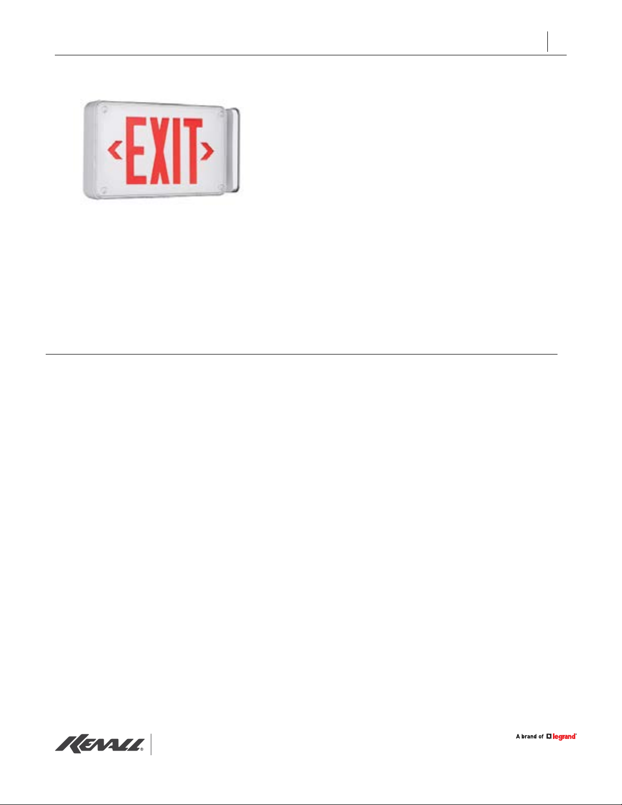
MILLENIUM METREX
METEL SERIES
™
INSTALLATION INSTRUCTIONS
IMPORTANT SAFEGUARDS
READ AND FOLLOW ALL SAFETY INSTRUCTIONS
• DO NOT USE OUTDOORS.
• DO NOT MOUNT NEAR GAS OR ELECTRIC HEATERS.
• EQUIPMENT SHOULD BE MOUNTED IN LOCATIONS AND AT HEIGHTS WHERE
IT WILL NOT BE SUBJECTED TO TAMPERING BY UNAUTHORIZED PERSONNEL.
• THE USE OF ACCESSORY EQUIPMENT NOT RECOMMENDED BY THE
MANUFACTURER MAY CAUSE AN UNSAFE CONDITION.
• DO NOT USE THIS EQUIPMENT FOR OTHER THAN ITS INTENDED USE.
When using electrical equipment, basic safety precautions should always be followed, including the following:
THIS PRODUCT MUST BE INSTALLED IN ACCORDANCE WITH THE APPLICABLE INSTALLATION CODE BY A PERSON FAMILIAR WITH
THE CONSTRUCTION AND OPERATION OF THE PRODUCT AND THE HAZARDS INVOLVED. DISCONNECT POWER TO ALL CIRCUITS
BEFORE WIRING FIXTURE. INSTALL IN ACCORDANCE WITH ALL NATIONAL, STATE, AND LOCAL CODES. DO NOT CONNECT TO
AN UNGROUNDED SUPPLY. READ ALL FIXTURE MARKINGS AND LABELS TO ENSURE CORRECT INSTALLATION OF FIXTURE.
SUPPLEMENTAL INSTRUCTIONS MAY BE LOCATED ON THE FIXTURE, IN ADDITION TO THIS INSTRUCTION SHEET, REGARDING
ORIENTATION, OR MOUNTING RESTRICTIONS.
SAVE THESE INSTRUCTIONS
1
APPLICATIONS
THIS PRODUCT MUST BE INSTALLED IN
ACCORDANCE WITH THE APPLICABLE
INSTALLATION CODE BY A PERSON FAMILIAR
WITH THE CONSTRUCTION AND
OPERATION OF THE PRODUCT AND THE
HAZARDS INVOLVED. FOLLOW ANY SPECIFIC
INSTRUCTIONS ON LUMINAIRE LABELS.
Preparation
• Read all xture markings and labels to
insure correct installation of the xture.
Additional information may be located on
the xture or in supplemental instructions
sheets, separate from this instruction sheet,
regarding orientation,mounting restrictions
and optional equipment.
• For Peace of Mind Warranty, xture must be
mounted to building with at least 4 fasteners
(4 point mounting). Attachment to the
electrical box only is NOT recommended.
• WARNING: Disconnect power to the circuit
before wiring xture.
• Minimum 12” supply wire pigtails
must extend from electrical junction box
for eld connections within xture enclosure.
• Drilling Tip: Drill small pilot holes from
inside, using drill points as guides. Enlarge
holes from outside, using spade bits and
light pressure to reduce “digging in” and
slow drill speed to prevent material
overheating. Remove burrs and plastic
chips from parts prior to assembly.
WALL MOUNTING (Fig.1): Remove SHIELD
and STENCIL ASSEMBLY. RemoveELECTRICA
L CHASSIS by disengaging tabs in upper corners.
Remove REFLECTOR (if provided). Locate
appropriate REAR PANEL drillpoints and drill (4)
5/16” dia. mounting holes and (1) hole of
suitable size for supply wire entry. Place
HOUSING over an installed electrical
junction box (drill points provided for temporary
j-box attachment prior to permanent mounting).
Locate and drill 4 pilot holes in mounting surface
using REAR PANEL as a template. For wet
location installation, attach self-adhesive pad
GASKET to REAR PANEL. Using 1/4-20 fasteners
and anchors appropriate for the mounting
surface (not supplied), attach HOUSING
to structure.
www.kenall.com | P: 800-4-Kenall | F: 262-891-9701 | 10200 55th Street Kenosha, Wisconsin 53144, USA
This product complies with the Buy American Act: manufactured in the United State swith more than 50% of the component cost of US origin It may be covered by patents
found at www.kenall.com/patents. Content of specication sheets is subject to change; please consult www.kenall.com for current product details. ©2019 Kenall Mfg.Co.
F-2189
Page 2

INSTALLATION (cont’d)
INSTALLATION INSTRUCTIONS
2
CANOPY MOUNTING (Figs. 1, 2, 4): Remove front
SHIELD and STENCIL ASSEMBLY.
Remove ELECTRICAL CHASSIS by disengaging tabs
in upper corners. Remove REFLECTOR
(if provided). Locate appropriate HOUSING drill
points and drill (2) 5/16” dia. holes for
MOUNTING CANOPY attachment and (1) hole of
suitable size for supply wire entry. Place
MOUNTING PLATE over an installed electrical
junction box (slotted holes provided for
temporary j-box attachment prior to permanent
mounting). Locate and drill 4 pilot holes in
mounting surface using MOUNTING PLATE as a
template. For wet location installation, attach
self-adhesive pad GASKET to MOUNTING PLATE.
Using 1/4-20 fasteners and anchors
appropriate for the mounting surface (not supplied),
attach MOUNTING PLATE to structure.
Connect supply ground to GROUND WIRE provided.
For wet location installation, attach selfadhesive
pad GASKET to CANOPY COVER. Using HARDWARE
provided, attach CANOPY
COVER and HOUSING to CANOPY
MOUNTING PLATE.
CONDUIT ATTACHMENT(Fig. 5) ½” trade size
conduit may be used for power entry into top or
end of HOUSING or into center of REAR PANEL.
Locate suitable drill point and drill 7/8” dia.
hole. HOUSING is reversible for conduit entry
from either end (Note UP indicator). Use proper
conduit hub and locknut for wet or damp/dry
location installation (not supplied).
Applications
Millenium Metrex METDU, METDW,
MWESW series
Features
• Sealed, maintenance-free nickel-cadmium
battery. EL option is suitable for use in
10ºC to 40°C environments. EL-CW option
includes a thermostatically controlled battery
warmer and is suitable for use in -40°C to
40°C environments.
• Self-testing circuitry automactically conditions
the battery and performs regularly scheduled
tests that conform to NFPA 101 Life Safty
Code. Self-diagnostic circuitry monitors
battery, charger, power transfer and lamp
functions.
ALL MOUNTING TYPES (Fig. 1, 3, 4) Congure
DIRECTIONAL ARROWs as needed. To
remove DIRECTIONAL ARROW COVER, use 7/16”
nut driver (not supplied) to loosen
RETAINER NUT approx. one complete turn and push
in cover from outside. Tighten RETAINER
NUT to secure COLOR FILTER PANEL and aluminum
LIGHT MASK (if provided). Install
ELECTRICAL CHASSIS. Install REFLECTOR (if
provided), routing supply wires thru center hole
(if wall mounted). Route supply wires around
ELECTRICAL CHASSIS and connect to
appropriate push-in connectors. Connector lead
color coding: White= Neutral, Black= 120V,
Orange= 277V, Blue= 347V. Install front STENCIL
ASSEMBLY and SHIELD to HOUSING using
Posigrip fasteners (included) and 9500 screwdriver
(ordered separately).
www.kenall.com | P: 800-4-Kenall | F: 262-891-9701 | 10200 55th Street Kenosha, Wisconsin 53144, USA
This product complies with the Buy American Act: manufactured in the United State swith more than 50% of the component cost of US origin It may be covered by patents
found at www.kenall.com/patents. Content of specication sheets is subject to change; please consult www.kenall.com for current product details. ©2019 Kenall Mfg.Co.
Installation
• Fixture is shipped with battery
disconnected.
• Follow Kenall Installation Instruction Sheet
F-2189 FOR proper mounting, assembly and
wiring of unit.
• After installing electrical chassis and making
eld wiring connections ( AC power OFF),
connect polarized 2-pin battery connector to
PC board assembly.
• Exit legend will illuminate for a few seconds
and then extinguish. This signals that battery
is properly connected and is protected from
discharging until AC power is established.
• Attach front stencil assembly and shield.
F-2189
Page 3
• Applications Metrex Egress METEL Series
wall surface mount unit equipment for high
abuse environments. See xture label
for restrictions.
Features
• Sealed, maintenance-free nickel-cadmium
battery. Standard xture is suitable for use in
10°C (50°F) to 45°C (113°F) environments.
CEL option includes a thermostatically
controlled battery warmer and is suitable
for use in -30°C (-22°F) to 45°C (113°F)
environments. Follow Kenall Instruction Sheet
F-2929 for proper wiring of unit.
• Self-testing circuitry automatically conditions
the battery and performs regularly scheduled
tests that conform to NFPA 101Life Safety
Code. Self-diagnostic circuitry monitors
battery, charger, power transfer and lamp
functions.
INSTALLATION INSTRUCTIONS
3
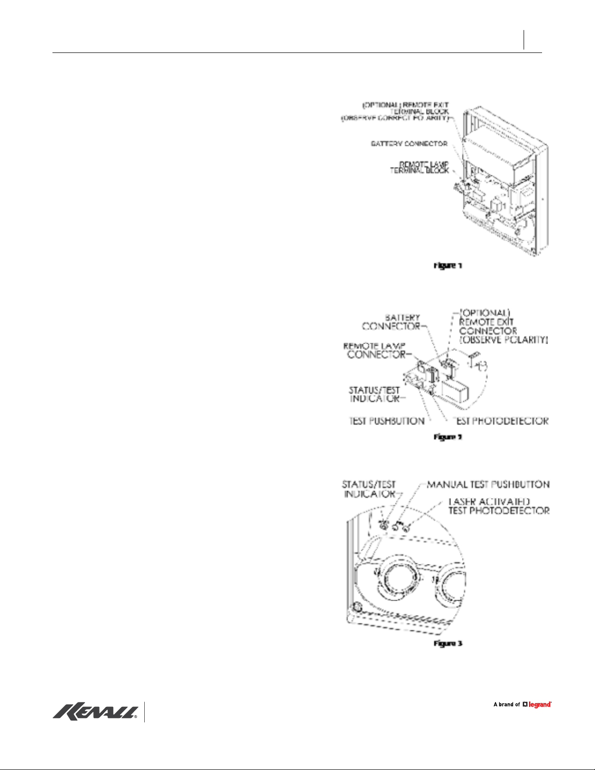
Installation (Figs. 2, 3)
• Follow Kenall Instruction Sheet F-2932 for
proper mounting,assembly and wiring of unit.
Start Up (Figs. 2, 3)
• Do not apply power to xture unless supply
can be maintained for at least 7 days without
interruption.
• If battery is not connected when power is
applied, the selfdiagnostic feature will detect
the missing battery and the status LED will
display a steady red signal. Connect the
battery and reset the system by pressing
and holding the manual test pushbutton for
approximately 7 seconds.
• Battery connection sequence: Always connect
BATTERY CONNECTOR 1 rst and BATTERY
CONNECTOR 2 (if equipped) second. Always
disconnect in reverse order.
www.kenall.com | P: 800-4-Kenall | F: 262-891-9701 | 10200 55th Street Kenosha, Wisconsin 53144, USA
This product complies with the Buy American Act: manufactured in the United State swith more than 50% of the component cost of US origin It may be covered by patents
found at www.kenall.com/patents. Content of specication sheets is subject to change; please consult www.kenall.com for current product details. ©2019 Kenall Mfg.Co.
F-2189
Page 4

INSTALLATION (cont’d)
INSTALLATION INSTRUCTIONS
4
Battery Conditioning
• Upon initial power-up, the xture will supply
a trickle charge to the battery for 90 minutes.
Then it will switch to full charge mode for
approximately 24 hours. The xture will
thencondition the battery with a pair of 90
minute discharge and 24 hour
recharge cycles.
Load Learning (Fig. 3)
• During the nal discharge/recharge
cycle of the battery conditioning function,
the self-diagnostic feature will
measure the operating current of the
internal and external (if equipped
emergency lamps and external LED exit
sign (RXR option only).
CAUTION: To avoid electrical overload, total
connected lamp load (factory and eld installed)
should not exceed output rating.
User Initiated Tests (Fig. 3)
• A single momentary actuation of the laseractivated photodetector (see g.1) or the
manual test pushbutton will initiate a
one-minute test. The normally off emergency
lamps will come on and the status LED will
display single green ashes,signaling a test
is in progress.
• Within the rst 5 seconds, pressing the
manual test pushbutton twice will change
the test duration to 30 minutes, three times
for 60 minutes, or four times for 90 minutes.
• Actuating the photodetector or the
manual test pushbutton after the rst 5
seconds will cancel any user initiated test.
Automatic Tests (Fig. 3)
• Automatic tests meet or exceed requirements
NFPA 101 Life Safety Code, Section 4.6,
Article 7.9.3: Monthly Test 30 minute cycle
every 30 days.
• Any time the total emergency lamp load
(internal or external) or the remote exit sign
load (RXR option only) is intentionallyaltered,
the system must be reset by pressing and
holding themanual test pushbutton for
approximately 7 seconds. Failure to do so will
result in a lamp fault indication.
Normal Operation
Normal operation is indicated by a steady
green signal from the status LED. This indicates t
he fully charged battery is receiving a
maintenance (trickle) charge and normal
A power is present. The normally off emergency
lamps will be off and any normally on remote
exit signs (RXR option only) will operate from
normal AC power.
www.kenall.com | P: 800-4-Kenall | F: 262-891-9701 | 10200 55th Street Kenosha, Wisconsin 53144, USA
This product complies with the Buy American Act: manufactured in the United State swith more than 50% of the component cost of US origin It may be covered by patents
found at www.kenall.com/patents. Content of specication sheets is subject to change; please consult www.kenall.com for current product details. ©2019 Kenall Mfg.Co.
• These tests allow the self-diagnostic
circuit to monitor battery discharge and
power transfer functions and exercise the
battery to optimize its capacity. The normally
off emergency lamps will come on and
the status LED will display single green
ashes,signaling a test is in progress.
• Actuating the TEST PHOTODETECTOR or the
manual TEST PUSHBUTTON after the rst 5
seconds will cancel any automatic test and
delay by 12 hours all subsequent automatic
tests.
Emergency Operation
• When the AC voltage drops below a
predetermined level either due to a power
failure or a brownout condition, the unit
willswitch to emergency operation. The status
LED will turn off, signaling normal AC power
is not present. Unit will remain in emergency
operation for 10 minutes after resumption of
normal AC power to allow normal lighting
systems to return to full brightness.
F-2189
Page 5
INSTALLATION INSTRUCTIONS
5
• Upon resumption of normal operation there
will be a 90 minute time delay before a full
charge is applied to the battery to allow the
unit to reach normal operating temperature
(CEL option). During full charge the status
LED will display two green ashes. The
charger will return a depleted battery to full
capacity within 24 hours. When the battery
has reached full capacity, maintenance
(trickle) charging begins and the status
LED will display steady green.
Load Learning (Fig. 3)
• In the event of a prolonged power outage,
the battery is protected from deep discharge
by a low voltage disconnect circuit.
CAUTION: To avoid electrical overload, total
connected lamp load (factory and eld installed)
should not exceed output rating.
• Any time the total emergency lamp load
(internal or external) or the remote exit sign
load (RXR option only) is intentionallyaltered,
the system must be reset by pressing and
holding themanual test pushbutton for
approximately 7 seconds. Failure to do so will
result in a lamp fault indication.
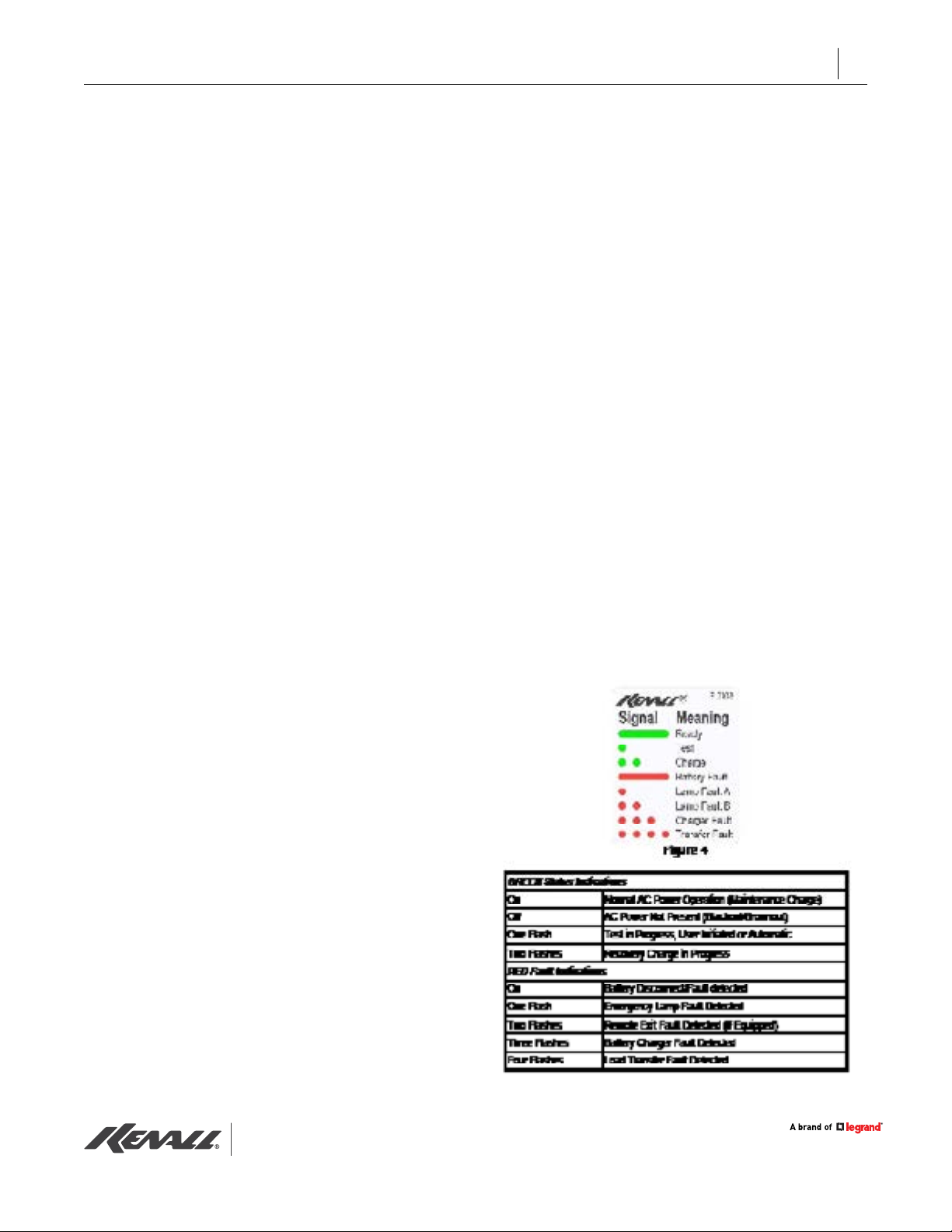
Emergency Lamps: The emergency lamp
condition is constantly monitored during test
cycles. A variation of more than 10% of
nominal load current will cause the
status indicator to display single red ashes.
Remote Exits (if equipped): The LED
lamp condition is constantly monitored during
normal operation and test cycles. A variation
of more than 25% of nominal load current
will cause the status indicator to
display two red ashes.
Charger: The charger function is constantly
monitored during battery charging. A
charger malfunction will terminate the
charge and return the unit to normal operation.
The status indicator will display three red ashes.
Transfer: The normal-to-emergency
and emergency-tonormal power transfer
functions are monitored at the beginning and
end of each test cycle. A transfer circuit
malfunction will cause the status indicator to
display four red ashes.
Status Indicator (Figs. 3, 4)
• A single dual-color status/fault LED is
provided to allow monitoring of the circuit
function. See g. 2.
Self-Diagnostics (Figs. 3, 4)
Battery: The battery condition is
constantly monitored during normal operation,
tests and charge cycles. A malfunctioning or
end-of-life battery will terminate any charge or
test and return the unit to normal operation. The
status indicator will display steady red.
www.kenall.com | P: 800-4-Kenall | F: 262-891-9701 | 10200 55th Street Kenosha, Wisconsin 53144, USA
This product complies with the Buy American Act: manufactured in the United State swith more than 50% of the component cost of US origin It may be covered by patents
found at www.kenall.com/patents. Content of specication sheets is subject to change; please consult www.kenall.com for current product details. ©2019 Kenall Mfg.Co.
F-2189
Page 6
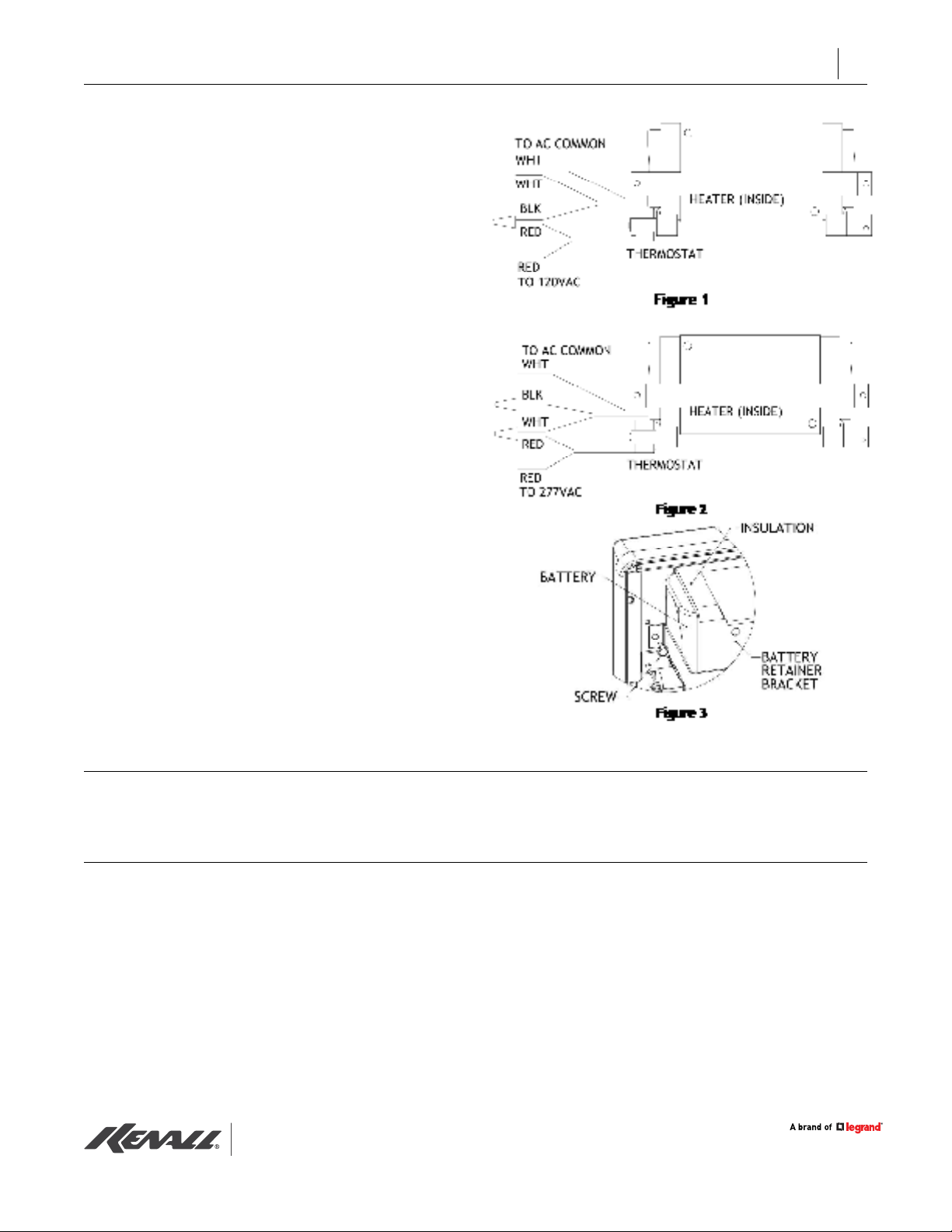
120VAC Installation (Fig.1)
• Connect the WHITE wires from the BATTERY
HEATER to COMMON.
• Connect one RED wire from the THERMOSTAT
to the BLACK wire from the BATTERY HEATER.
• Connect the second RED wire from the
THERMOSTAT to 120VAC supply.
277VAC Installation (Fig.2)
• Connect one WHITE wire from the BATTERY
HEATER to COMMON.
• Cap off the BLACK wire from the
BATTERY HEATER.
• Connect one RED wire from the
THERMOSTAT to the second WHITE wire
from the BATTERY HEATER.
• Connect the second RED wire from the
THERMOSTAT to 277VAC supply.
INSTALLATION INSTRUCTIONS
6
Battery Maintenance (Fig.3)
• To remove battery, remove (2) screws
securing BATTERY RETAINER BRACKET.
Remove bracket.
• Unwrap the foil lined berglass INSULATION
from the BATTERY. There is no need to
remove the INSULATION.
• Installation is the reverse of removal.
CUSTOMER SERVICE
For technical assistance, call 1-800-4KENALL (1-800-453-6255).
WARRANTY
For warranty information visit www.kenall.com/Resources/Certied-Performance-Warranties
www.kenall.com | P: 800-4-Kenall | F: 262-891-9701 | 10200 55th Street Kenosha, Wisconsin 53144, USA
This product complies with the Buy American Act: manufactured in the United State swith more than 50% of the component cost of US origin It may be covered by patents
found at www.kenall.com/patents. Content of specication sheets is subject to change; please consult www.kenall.com for current product details. ©2019 Kenall Mfg.Co.
F-2189
 Loading...