

Page 1
No: 341090 – 10/14
Pass & Seymour
®
De-Hummer® Fan Control and Dimmer: CFL/LED 150W, 120VAC, 60 Hz; Incandescent 300W, 120VAC, 60 Hz;
Fan Control: 1.6A, 120VAC, 60Hz
Gradateur et Contrôleur de Ventilateur De-Hummer® : CFL/LED 150 W, 120 VCA, 60 Hz; Incandescents 300 W,
120 VCA, 60 Hz; Contrôleur de ventilateur 1,6 A, 120 VCA, 60 Hz
De-Hummer® Control de Ventilador y Atenuado: CFL/LED 150 W, 120 VCA, 60 Hz; Incandescente 300 W, 120 VCA,
60 Hz; Control de ventilador 1,6 A, 120 VCA, 60 Hz
Installation Instructions • Instructions d’Installation • Instrucciones de Instalación
Catalog Number(s) • Numéro(s) de Catalogue • Les Numéros de Catálgo: LSCLDC163P
Country of Origin: Made in China • Pays d’origine: Fabriqué en Chine • País de origen: Hecho en China
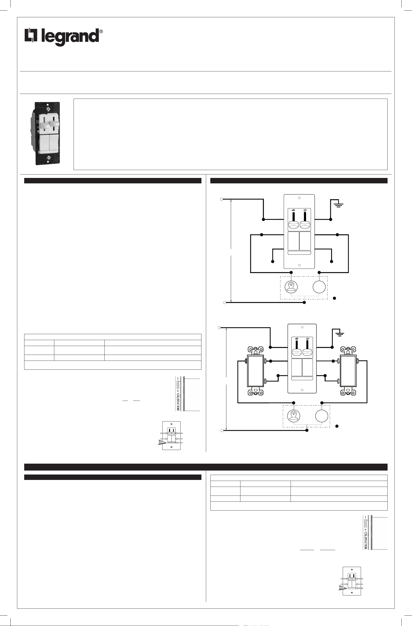
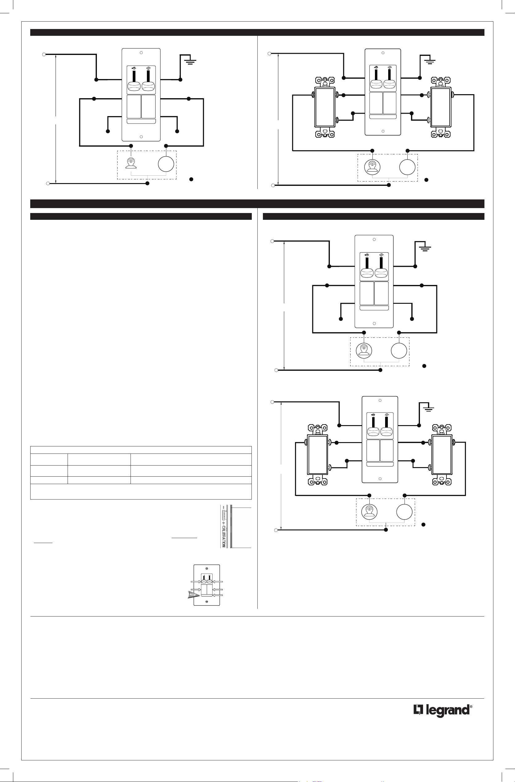
WIRING DIAGRAM FOR 3-WAY INSTALLATION
READ AND SAVE THESE INSTRUCTIONS
To be installed by a certified electrician or other qualified person.
WARNING – To prevent severe shock or electrocution, always turn power
off at the service panel before installing this unit, working on the circuit,
or changing a lamp.
CAUTION: To reduce the risk of overheating and possible damage to
other equipment:
• Do not install dimmer to control a receptacle, a motor-operated appliance
or a transformer-supplied appliance.
• Use only with incandescent or compatible dimmable CFL /LED bulbs
which screw into conventional incandescent lamp sockets (compatible
bulbs listed at www.legrand.us).
Connect to 120VAC, 60 Hz power source only.
A minimum load of 10W is recommended for optimal operation of
the dimmer.
Use copper wire only.
LIRE ET CONSERVER CES INSTRUCTIONS
Doit être installé par un électricien certifié ou une autre personne qualifiée.
AVERTISSEMENT – Pour éviter tout choc électrique ou une électrocution,
toujours couper l’électricité au niveau du panneau d’alimentation avant
d’installer cette unité, de travailler sur le circuit électrique ou de changer
une lampe.
ATTENTION : Pour réduire le risque de surchauffe ou d’endommagement
d’autres pièces d’équipement :
• Ne pas installer un gradateur pour contrôler une prise électrique, ou un
appareil ménager équipé d’un moteur ou alimenté par un transformateur.
• À n’utiliser qu’avec des ampoules à incandescence ou variable à
luminosité CFL/ LED ampoules compatibles qui se vissent dans
des douilles d’ampoules à incandescence traditionnelles (ampoules
compatibles énumérés à www.legrand.us).
Connecter à une source de 120 VCA, 60 Hz uniquement.
Une charge minimale de 10W est recommandée pour un fonctionnement
optimal du gradateur.
N’utiliser que des fils en cuivre.
LEA Y CONSERVE ESTAS INSTRUCCIONES
Para ser instalado por un electricista certificado o persona competente.
ADVERTENCIA – Para evitar descargas eléctricas serias o electrocución,
antes de instalar, trabajar en el circuito o cambiar una lámpara de este
atenuador apague siempre el suministro eléctrico en el panel de servicio.
PRECAUCIÓN: Para reducir el riesgo de sobrecalentamiento y posibles
daños a otros equipos:
• No instale un atenuador para controlar un tomacorriente, un
electrodoméstico que funciona con motor o un electrodoméstico con
transformador.
• Utilícese solamente con bombillas incandescentes CFL o LED
atenuables que se atornillan en portalámparas incandescentes
convencionales (bombillas compatibles enumerados en
www.legrand.us).
Conecte solamente a un suministro eléctrico de 120 VAC, 60 Hz.
Una carga minima de 10W se recomienda para un funcionamiento óptimo
del atenuador.
Utilice únicamente alambres de cobre.
IMPORTANT NOTES:
1. All Fan Speed Controls can be damaged by improper wiring. Check for short circuits prior to installing the fan
speed control.
Procedure for short circuit check:
a. Disconnect power to circuit by removing fuse or turn circuit breakers OFF.
b. Install a switch instead of the fan speed control. Turn the switch to the “ON” position.
c. If the fan fails to turn ON and OFF with the switch, the wiring may be incorrect.
d. Correct wiring, if necessary and retest.
e. Install the fan speed control only after the fan operates properly with the switch.
2. Protect from dirt and dust. The Fan Speed Control can be damaged from contaminants encountered during the
construction process. The control should not be installed until the construction process is complete.
Any Fan Speed Control damage due to improper installation is not covered under warranty.
Attention: In most retrofit applications, it is necessary to add an additional wire from the Control to the Fan. This
is necessary to achieve independent control and maximize the versatility of the Fan & Light. The additional wire
should not be confused with the Neutral wire, usually White, nor the Ground wire, normally Bare or Green. Retrofit
installations should be done only by a certified electrician.
INSTRUCTIONS:
1. Prior to installation, set the fan to its highest speed and the light to its brightest setting.
2. Disconnect power to the circuit.
3. Strip installed wires per the chart below.
4. Connect the Control’s wires to installed wiring as shown in the Wiring Diagram using the wire connectors provided.
5. Mount the Control to outlet box using mounting screws provided.
6. Attach the wall plate.
7. Set the fan control to its OFF (lowest) position.
8. Restore power to the circuit.
9. Be sure the fan starts and does not stall in any of the ON positions. The best operation may be obtained by
starting the fan in the highest setting and then moving the control to the desired speed. Do not allow the fan to
remain stalled. This may overheat the fan. DO NOT USE THE PULL CHAIN TO CONTROL THE FAN SPEED
AFTER INSTALLATION OF THIS CONTROL.
10. Dimmer may require adjustment to the low end setting to reliably start and/or remove flickering in bulbs. To
adjust, DISCONNECT POWER FROM CIRCUIT, and remove the wall plate. Use a small insulated, flat tipped
screwdriver to adjust the trim pot wheel, which is accessible via the slot (marked “CALIBRATION”) provided on
the strap (Figure 1). Turn the wheel downwards to increase the minimum light intensity setting and turn the
wheel upwards to decrease light intensity. Next, install the wall plate, restore the power and test. Repeat above
as necessary. Note: Never adjust trim pot when circuit is live.
WIRE CONNECTOR USAGE CHART
CONNECTOR WIRE COMBINATIONS WIRE STRIP LENGTH
LARGE 1 #14 + 1 #18
SMALL 1 #18 3/8" (9.5mm) for Solid wire
Strip wires per chart. Align ends. Push wires firmly into connector. Screw connector securely onto wires.
Note: The Control is supplied with #18 wire.
Note: It is normal for the dimmer to feel warm during operation. Use a separate neutral wire
for each phase of a multiphase system containing a dimmer, and for high power single phase
applications where flickering is present.
Any combination of dimmers and other devices may be ganged together.
OPERATING INSTRUCTIONS:
Toggle the light or fan switch provided to turn the respective unit ON or OFF.
To change lighting level or fan speed, slide the respective knob up or down until
desired level is reached.
Use only copper or copper clad wire with this device.
LIGHT MODULE: (Sold separately, Catalog #TM8LMCC)
Transform in minutes a standard dimmer into an illuminated dimmer
(ON when light is OFF) – allows the dimmer to be found in the dark.
Average 20-year life expectancy.
No wiring – quick snap-in installation.
7/16" (11mm) for Solid wire
1/2" (13mm) for Stranded wire
Light Level
Control Knob
Light Switch
Figure 1
Fan Speed
Control
Knob
Fan Switch
Optional
Light Module
120VAC
120VAC
60Hz
INSTALLATION DIAGRAM
WIRING DIAGRAM FOR SINGLE POLE INSTALLATION
HOT (Black Wire)
BLACK
WIRE
YELLOW
WIRE
YELLOW WIRE
WITH 3-WAY
60Hz
NEUTRAL (White Wire)
HOT (Black Wire)
BLACK
OR
COMMON
3-WAY SWITCH FOR LIGHT 3-WAY SWITCH FOR LIGHT
NEUTRAL (White Wire)
LABEL
CAP WITH WIRE NUT CAP WITH WIRE NUT
LIGHT
CEILING FAN
WITH
LIGHT
BLACK
WIRE
YELLOW
WIRE
YELLOW
WIRE WITH
3-WAY LABEL
LIGHT
CEILING FAN
WITH
LIGHT
GREEN
WIRE
RED
WIRE
FAN
GREEN
WIRE
RED
WIRE
RED WIRE
WITH
3-WAY LABEL
FAN
RED WIRE
WITH 3-WAY
GROUND
LABEL
REPRESENTS WIRE NUT
GROUND
REPRESENTS WIRE NUT
BLACK
OR
COMMON
INSTRUCTIONS EN FRANÇAIS
REMARQUES IMPORTANTES :
Attention : Dans la plupart des applications de mise à niveau, il est nécessaire d’ajouter un fil entre le contrôleur
et le ventilateur. Ceci est nécessaire pour assurer un contrôle indépendant et maximiser la souplesse d’utilisation
de la lampe et du ventilateur. Ce fil supplémentaire ne doit pas être confondu avec le fil du neutre, habituellement
blanc, ou le fil de terre, habituellement nu ou vert. Les installations de mise à niveau doivent être effectuées par un
électricien certifié uniquement.
INSTRUCTIONS :
1. Avant l’installation, régler le ventilateur à sa vitesse la plus élevée et la lumière à son intensité maximale.
2. Couper l’alimentation du circuit.
3. Dénuder les fils installés selon les indications du tableau ci-dessous.
4. Raccorder les fils du gradateur aux fils installés comme indiqué sur le Diagramme de câblage en utilisant les
5. Fixer le contrôleur sur la boîte à l’aide des vis de fixation fournies.
6. Fixer la plaque murale.
7. Régler le contrôleur du ventilateur sur sa position la plus basse (OFF/ARRÊT).
8. Remettre le circuit sous tension.
9. S’assurer que le ventilateur démarre et ne s’arrête dans aucune des positions ON (MARCHE). Pour assurer
10. Le gradateur peut avoir à être réglé aux faibles intensités pour que certaines lampes s’allument correctement et/
connecteurs de fils fournis.
le meilleur fonctionnement, il peut s’avérer utile de démarrer le ventilateur à sa position la plus élevée, puis de
réduire sa vitesse jusqu’à la valeur désirée. Ne pas laisser le ventilateur en position « calée ». Ceci pourrait faire
surchauffer le ventilateur. NE PAS UTILISER LA CHAÎNE POUR CONTRÔLER LA VITESSE DU VENTILATEUR
APRÈS L’INSTALLATION DE CE CONTRÔLEUR.
ou ne clignotent pas. Pour cela, COUPER L’ALIMENTATION DU CIRCUIT et retirer la plaque murale. Utiliser
un petit tournevis plat isolé pour régler le potentiomètre qui est accessible à travers la fente (« CALIBRATION »)
située sur la bande (Figure 1). Tourner la mollette vers le bas pour augmenter le réglage de l’intensité
lumineuse minimale et tourner la mollette vers le haut pour réduire l’intensité lumineuse. Ensuite, remonter
la plaque murale, remettre sous tension et tester. Répéter les étapes ci-dessus au besoin. Remarque : ne
jamais régler le potentiomètre si le circuit est sous tension.
TABLEAU D’UTILISATION DES CONNECTEURS DE FILS
CONNECTEUR COMBINAISONS DE FILS
GROS 1 #14 + 1 #18
LONGUEUR DE DÉNUDAGE DES FILS
7/16 po (11 mm) pour fil massif
1/2 po (13 mm) pour fil torsadé
PETIT 1 #18 3/8 po (9,5 mm) pour fil massif
Dénuder les fils selon les indications du tableau. Aligner les extrémités. Enfoncer les fils fermement dans le
connecteur. Bien visser le connecteur sur les fils. Remarque : Le contrôleur est fourni avec des fils #18.
Remarque : Il est normal que le gradateur soit tiède au toucher en cours de
fonctionnement. Utiliser un neutre séparé pour chaque phase d’un système multiphasé
contenant un gradateur, et pour les applications monophasées à forte puissance lorsqu’il
existe un scintillement.
N’importe quelle combinaison de gradateurs et d’autres dispositifs peuvent être
installés ensemble.
INSTRUCTIONS D’UTILISATION
Basculer l’interrupteur de la lumière ou du ventilateur pour l’allumer ou l’éteindre.
Pour modifier l’intensité lumineuse ou la vitesse du ventilateur, faire glisser le curseur
Figure 1
correspondant jusqu’au niveau souhaité.
N’utiliser ce dispositif qu’avec des fils en cuivre ou cuivrés.
MODULE LUMINEUX : (vendu séparément,
n° de catalogue TM8LMCC)
Permet de transformer en quelques minutes un gradateur standard
en un gradateur lumineux (ALLUMÉ lorsque la lumière est
ÉTEINTE) – Permet de trouver le gradateur dans le noir.
Durée de vie moyenne : 20 ans
Pas de câblage – Installation rapide par enfichage
Bouton du
gradateur
d’intensité
lumineuse
Interrupteur
de la lumière
Bouton
du contrôleur
de vitesse
du ventilateur
Interrupteur
du ventilateur
Optionnel module
lumineux
341090_revB_Dimmers IS_11x17.indd 1 10/6/14 4:13 PM
Page 2
800.223.4185
1.877.BY.LEGRAND
www.legrand.us
www.legrand.ca
No: 341090 – 10/14
© Copyright 2014 Legrand All Rights Reserved.
© Copyright 2014 Tous droits réservés Legrand.
© Copyright 2014 Legrand Todos los derechos reservados.
For covering patents, see www.legrand.us/patents
Pour connaître les brevets applicables, consultez www.legrand.us/patents
Para obtener patentes de protección, visite www.legrand.us/patents
DIAGRAMME D’INSTALLATION
DIAGRAMME DE CÂBLAGE POUR INSTALLATION UNIPOLAIRE
SCHÉMA DE CÂBLAGE POUR INSTALLATION TRIPOLAIRE
PARA ALAMBRE
DIAGRAMA DE CABLEADO PARA INSTALACIÓN DE 3 VÍAS
CHAUD (fil noir)
TERRE
FIL
FIL ROUGE
AVEC
ÉTIQUETTE
3 VOIES
ISOLER AVEC UN
REPRÉSENTE UN
CONNECTEUR DE FIL
120VAC
60Hz
FIL JAUNE
AVEC
ÉTIQUETTE
3 VOIES
ISOLER AVEC UN
CONNECTEUR DE FIL
NEUTRE (fil blanc)
FIL
NOIR
FIL JAUNE FIL ROUGE
LUMIÈRE
VENTILATEUR
DE PLAFOND
AVEC
LUMIÈRE
VERT
CONNECTEUR DE FIL
VENTILATEUR
INSTRUCCIONES EN ESPAÑOL
NOTAS IMPORTANTES:
1. Todos los controles de velocidad de ventilador pueden dañarse a causa de un cableado incorrecto. Antes de
instalar el control de velocidad de ventilador, revise en busca de cortocircuitos.
Procedimiento de revisión para localizar cortocircuitos:
a. Desconecte el suministro eléctrico al circuito quitando el fusible o apagando los cortacircuitos (OFF).
b. Instale un interruptor en lugar del control de velocidad de ventilador. Coloque el interruptor en la posición
encendido (ON).
c. Encienda el suministro eléctrico. Si el cortacircuitos se dispara, existe un cortocircuito. Si el ventilador no se
enciende y apaga con el interruptor, el cableado podría estar incorrecto.
d. Si es necesario, corrija el cableado, y pruebe nuevamente.
e. Instale el control de velocidad de ventiladorúnicamente después de que el ventilador funcione
apropiadamente con el interruptor.
2. Proteja contra la suciedad y el polvo. El control de velocidad de ventilador puede dañarse por contaminantes
que se generan durante el proceso de construcción. El control no debe instalarse antes de terminar la
construcción.
Cualquier daño del control de velocidad de ventilador causado por una instalación incorrecta no está
amparado por la garantía.
Atención: En la mayoría de las aplicaciones de reacondi cionamiento, es necesario agregar un alambre. adicional
no debe confundirse con el alambre neutro, habitualmente blanco, ni con el alambre de conexión a tierra,
normalmente desnudo o verde. Las instalaciones de reacondicionamiento sólo deben ser realizadas por un
electricista certificado.
INSTRUCCIONES:
1. Antes de la instalación, ajuste el ventilador a su velocidad más alta y la luz a su posición de mayor intensidad.
2. Desconecte la corriente al circuito.
3. Desforre los alambres instalados de acuerdo con la tabla presentada abajo.
4. Conecte los alambres del control al cableado instalado, tal como se muestra en el Diagrama de cableado
usando los conectores para alambre suministrados.
5. Monte el control en la caja de salida con los tornillos de montaje suministrados.
6. Conecte la placa de pared.
7. Coloque el control de ventilador en su posición de APAGADO (más baja).
8. Restaure la corriente al circuito.
9. Asegúrese de que el ventilador arranque y que no se bloquee en ninguna de las cuatro posiciones de
ENCENDIDO. El mejor funcionamiento puede obtenerse arracando elventilador a la velocidad más alta y
luego moviendo el control a la velocidad deseada. No permita que el ventilador continúe bloqueado. Esto
podría causar recalentamiento. NO USE LA CADENA DE TIRO PARA CONTROLAR LA VELOCIDAD DEL
VENTILADOR DESPUÉS DE HABER INSTALADO ESTE CONTROL.
10. Es posible que el atenuador requiera ajuste a baja intensidad para encender lámparas o eliminar fluctuaciones
en las bombillas. Para ajustar, DESCONECTE LA ALIMENTACIÓN DEL CIRCUITO y quite la placa de pared.
Con un destornillador pequeño aislado de punta plana, ajuste la rueda del potenciómetro que es accesible a
través de la ranura (marcada “CALIBRATION”) situada sobre la banda (Figura 1). Gire la rueda hacia abajo
para aumentar la intensidad mínima de la luz y gire la rueda hacia arriba para disminuir la intensidad de la
luz. Luego, instale la placa de pared, restaure el suministro eléctrico y realice una prueba. Repita lo anterior
según sea necesario. Nota: Nunca ajuste el potenciómetro cuando el circuito está energizado.
TABLA DE UTILIZACIÓN DE LOS CONECTORES DE ALAMBRE
CONECTOR COMBINACIONES DE
ALAMBRES
GRANDE 1 #14 + 1 #18
PEQUEÑO 1 #18 3/8 pulg. (9.5 mm) para alambre sólido
Desforre los alambres de acuerdo con la tabla. Alinee los extremos. Empuje los alambres firmemente en el
conector. Atornille el conector en forma segura sobre los alambres.
Nota: El control se suministra con alambre #18.
Nota: Es normal que el atenuador se sienta tibio durante la operación. Utilice un alambre
neutro por separado para cada fase de un sistema multifase que contiene un atenuador,
y para aplicaciones monofásicas de alta potencia donde existan fluctuaciones.
Se puede instalar en grupo cualquier combinación de atenuadores y otros dispositivos.
INSTRUCCIONES DE OPERACIÓN:
Mueva la báscula del interruptor de luz o del ventilador suministrado para ENCENDER
o APAGAR la unidad respectiva.
Para cambiar el nivel luminoso o la velocidad del ventilador, deslice la perilla respectiva
hacia arriba o hacia abajo hasta alcanzar el nivel deseado.
Use solamente alambre de cobre o recubierto de cobre con este aparato.
MÓDULO LUMINOSO: (vendido separado, N° de catálogo TM8LMCC)
Transforme en minutos un control estándar del ventilador en un
control iluminado (ENCENDIDO cuando la luz está APAGADA) –
permite encontrar el control en la oscuridad.
20 años de expectativa de vida promedio.
Instalación con inserción rápida – no requiere cableado.
LONGITUD DE DESFORRADO
DEL ALAMBRE
7/16 pulg. (11 mm) para alambre sólido
1/2 pulg. (13 mm) para alambre trenzado
Perilla
de control
de nivel
luminoso
Interruptor
de luz
Figura 1
Perilla de control
de velocidad del
ventilador
Interruptor del
ventilador
Módulo de
luz opcional
CHAUD (fil noir)
NOIR
OU
COMMUN
120 VCA
60Hz
INTERRUPTEUR TRIPOLAIRE
POUR LA LUMIÈRE
NEUTRE (fil blanc)
ENERGIZADO (Alambre Negro)
120VAC
60Hz
NEUTRO (Alambre Blanco)
ENERGIZADO (Alambre Negro)
NEGRO
O
COMÚN
120 VCA
60Hz
INTERRUPTOR DE 3 VÍAS PARA LÁMPARA INTERRUPTOR DE 3 VÍAS PARA LÁMPARA
NEUTRO (Alambre Blanco)
FIL
NOIR
FIL
JAUNE
FIL JAUNE
AVEC ÉTIQUETTE
3 VOIES
LUMIÈRE
VENTILATEUR
DE PLAFOND
AVEC
LUMIÈRE
VERT
AVEC ÉTIQUETTE
VENTILATEUR
TERRE
FIL
FIL
ROUGE
FIL ROUGE
3 VOIES
INTERRUPTEUR TRIPOLAIRE
POUR LA LUMIÈRE
REPRÉSENTE UN
CONNECTEUR DE FIL
DIAGRAMA DE INSTALACIÓN
DIAGRAMA DE CABLEADO PARA INSTALACIÓN UNIPOLAR
ALAMBRE
NEGRO
ALAMBRE
AMARILLO
ALAMBRE
AMARILLO CON
ETIQUETA
3 VÍAS
SELLE CON TUERCA
PARA ALAMBRE
ALAMBRE
NEGRO
ALAMBRE
AMARILLO
ALAMBRE
AMARILLO CON
ETIQUETA 3 VÍAS
LUZ
LUZ
VENTILADOR
DE TECHO
CON
LÁMPARA
VENTILADOR
DE TECHO
CON
LÁMPARA
ALAMBRE
VERDE
ALAMBRE
SELLE CON TUERCA
VENTILADOR
ALAMBRE
VENTILADOR
TIERRA
ROJO
ALAMBRE
ROJO CON
ETIQUETA
3 VÍAS
PARA ALAMBRE
TIERRA
VERDE
ALAMBRE
ROJO
ALAMBRE
ROJO CON
ETIQUETA 3 VÍAS
REPRESENTA TUERCA
REPRESENTA TUERCA
PARA ALAMBRE
NOIR
OU
COMMUN
NEGRO
O
COMÚN
WARRANTIES
Lifetime Warranty. The device you have purchased is warranted under normal use against defects in
workmanship and materials for as long as you own the device. If the device fails due to manufacturing
defect during normal use, return the device for replacement to the store where purchased or send to:
Legrand, 50 Boyd Avenue, Syracuse, NY 13209
All requests for replacement must include a dated sales receipt (legible copies acceptable).
ALL OTHER WARRANTIES, INCLUDING BUT NOT LIMITED TO ANY WARRANTIES OF
MERCHANTABILITY OR FITNESS FOR A PARTICULAR PURPOSE, ARE LIMITED TO A PERIOD
OF TWO YEARS FROM THE DATE OF PURCHASE. YOUR SOLE AND EXCLUSIVE REMEDY
AGAINST LEGRAND UNDER ANY WARRANTY SHALL BE THE EQUIVALENT REPLACEMENT OF
THE DEVICE. IN NO EVENT SHALL ANY WARRANTY APPLY TO ANY DEFECT ARISING OUT OF
ANY ALTERATION OF THE DEVICE, IMPROPER WIRING, IMPROPER INSTALLATION, MISUSE,
ABNORMAL USE OR NEGLIGENCE. IN NO EVENT SHALL LEGRAND BE LIABLE FOR LOST
PROFITS, INDIRECT, SPECIAL, EXEMPLARY, INCIDENTAL OR CONSEQUENTIAL DAMAGES.
Some states do not allow limitations on how long implied warranties last and do not allow exclusion or
limitation of incidental or consequential damages. Some of the above limitations or exclusions may not
apply to every purchaser.
341090_revB_Dimmers IS_11x17.indd 2 10/6/14 4:13 PM
GARANTIES
Garantie à vie. L’appareil que vous venez d’acheter est garanti, sous condition d’utilisation normale,
contre tout défaut dans la fabrication et les matériaux tant qu’il est en votre possession. Si cet appareil
tombe en panne à cause de défauts de fabrication pendant son utilisation normale, le rapporter pour
qu’il soit remplacé, le cas échéant, là où vous l’avez acheté ou l’envoyer à: Legrand, 50 Boyd Avenue,
Syracuse, NY 13209.
Toute demande de remplacement doit contenir un reçu de vente (photocopies lisibles acceptées).
TOUTES AUTRES GARANTIES, Y COMPRIS MAIS NON LIMITEES A TOUTE GARANTIE DE
COMMERCIALISATION OU APTITUDE A SATISFAIRE UNE FONCTION PAR TICULIERE, SONT
LIMITEES A UNE PERIODE DE DEUX ANS A COMPTER DE LA DATE D’ACHAT. VOTRE RECOURS
UNIQUE ET EXCLUSIF CONTRE LEGRAND SOUS TOUTE GARANTIE EST LE REMPLACEMENT
EQUIVALENT DE VOTRE APPAREIL. EN AUCUN CAS LA GARANTIE NE S’APPLIQUE A DES
DEFAUTS DE FONCTIONNE MENT DUS A DES MODIFICATIONS DE L’APPAREIL, UN CABLAGE
INCORRECT, UNE INSTALLATION INCORRECTE, UNE MAUVAISE UTILISATION, UNE UTILISATION
ANORMALE OU DE LA NEGLIGENCE. EN AUCUN CAS LEGRAND N’EST RESPONSABLE POUR
UNE PERTE DE PROFIT, OU DES DEGATS INDIRECTS, PARTICULIERS, EXEMPLAIRES, MINEURS
OU CONSEQUENTS.
Certains états n’autorisent pas de limite sur la durée des garanties implicites et ne permettent pas
d’exclusion ou de limite quant aux dégâts mineurs ou conséquents. Il se peut que certaines des limites
ou exclusions ci-dessus ne s’appliquent pas à tous les acheteurs.
GARANTÍAS
Garantías de Por Vida: El aparato que Ud. ha comprado está garantizado bajo uso normal contra de
defectos de fábrica y materiales durante el tiempo que Ud. posea el aparato. Si el aparato falla debido
a defectos de fábrica durante uso normal, devuelva el aparato para su reemplazo a la tienda donde fue
adquirido o envíelo a: Legrand, 50 Boyd Avenue, Syracuse, NY 13209.
Todos los pedidos de reemplazos deben incluir un recibo de compra fechado (se aceptan copias
legibles).
TODAS LAS DEMÁS GARANTÍAS INCLUIDAS PERO NO LIMITADAS A CUALQUIER GARANTÍA
COMERCIAL O DE PARTICULARI DAD PARA UN PROPÓSITO ADECUADO, ESTÁN LIMITADAS
A UN PERÍODO DE DOS AÑOS A PARTIR DE LA FECHA DE COMPRA. SU ÚNICO Y EXCLUSIVO
DERECHO CON RESPECTO A LEGRAND BAJO CUALQUIER GARANTÍA SERÁ EL REEMPLAZO
POR UN APARATO EQUIVALENTE. EN NINGÚN CASO, NINGUNA GARANTÍA PODRÁ SER
APLICADA A NINGÚN DEFECTO QUE SURJA DE NINGUNA ALTERA CIÓN DEL APARATO,
CABLEADO IMPROPIO, INSTALACIÓN IMPROPIA, MAL USO, USO ANORMAL O NEGLIGENCIA.
BAJO NINGÚN CASO, SERÁ RESPONSABLE LEGRAND DE DAÑOS POR PÉRDIDAS EN
INGRESOS, INDIRECTOS, ESPECIALES, EJEMPLARES, INCIDENTALES, O CONSECUENTES.
Algunos estados no permiten limitaciones en la duración de las garantías implícitas y no permiten
exclusión o limitación de daños accidentales o consecuentes. Algunas de las limitaciones o exclusiones
arriba enunciadas podrán no ser aplicadas a cada comprador.
 Loading...