

LEGRAND LMBC-600, Wattstopper LMBC-600 User Manual
Wattstopper
®
DLM Wireless Network Bridge Module
No: 25224 – 08/17 rev. 3
Quick Start Guide • Guide de démarrage rapide • Guía de inicio rápido
Catalog Number • Numéro de Catalogue • Número de Catálogo: LMBC-600
Country of Origin: Made in China • Pays d’origine: Fabriqué en Chine • País de origen: Hecho en China
LMBC-600-U is BAA and TAA compliant (Product produced in the U.S.)
Voltage ...........................................................................................24VDC
Current Consumption ....................................................................... 20mA
Power Supply ..............................................Wattstopper Room Controller
Connection to the DLM Local Network .................................2 RJ-45 ports
Segment Network ......................................... BACnet IPv6 Mesh Network
DLM Local Network characteristics when using LMRC-11x/2xx room
controllers:
Low voltage power provided over Cat 5e cable (LMRJ); max current
800mA. Supports up to 64 load addresses, 47 communicating
devices including up to 4 LMRC-10x series and/or LMPL-101
controllers. Free topology up to 1,000’ max.
This unit is pre-set for Plug n’ Go™ operation, adjustment
is optional.
For full operational details, adjustment and more features of the product,
see the DLM System Installation Guide provided with Wattstopper room
controllers, and also available at www.legrand.us/wattstopper.
Installation shall be in accordance with all applicable regulations,
local and NEC codes. Wire connections shall be rated suitable for the
wire size (lead and building wiring) employed.
For Class 2 DLM devices and device wiring: To be connected to a Class
2 power source only. Do not reclassify and install as Class 1, or Power
and Lighting Wiring.
DESCRIPTION AND OPERATION
The LMBC-600 Network Bridge module provides a network
connection for a group of Wattstopper Digital Lighting
Management (DLM) Local Network room level devices.
The DLM local network must include at least one room/load
controller. Connecting the LMBC-600 to the DLM local network
then to either the DLM Segment Manager or a third party
system using the BACnet protocol exposes the status and
parameters of all connected devices to the broader network.
Environment ..............................................................For Indoor Use Only
Operating Temperature ............................. 32° to 158°F (0° to 70°C)
Storage Temperature ...............................23° to 176°F (-5° to 80°C)
Relative Humidity ................................... 5 to 95% (non condensing)
Indoor Use Only
Security
AES 128bit Key Encryption
Preshared key (non-commissioned state)
Key rotation after commissioning
Wireless
IEEE 802.15.4 , 2.4gHZ
Channels .................................11-26, default is 15 non-overlapping
.................................................................. 15, 20, 26 recommended
Wireless Standard .............................................................6LoWPAN
CoAP—constrained application protocol
Internal Antennas with Diversity
Bandwidth .................................................................. up to 156kbps
Range .................................................................. up to 100 ft. radius
Supported Standards ..........................Bacnet, IPV6, Contiki, RPL,SMRF
RoHS compliant
UL2043 Plenum rated
SPECIFICATIONS
Determine a suitable location for the LMBC-600. This will usually be in the ceiling closely located to the DLM local network devices to
be networked either directly in the room/space or just outside in a hallway for easier access. Classrooms and patient rooms are ideal for
hallway mounting of the bridge.
The LMBC-600 is UL2043 Plenum rated and comes with an DIN rail mounting plate for flexibility.
Warning: The LMBC-600 is a wireless device. Avoid mounting next to motors, large metal obstructions, or within 12” of another wireless
emitting device.
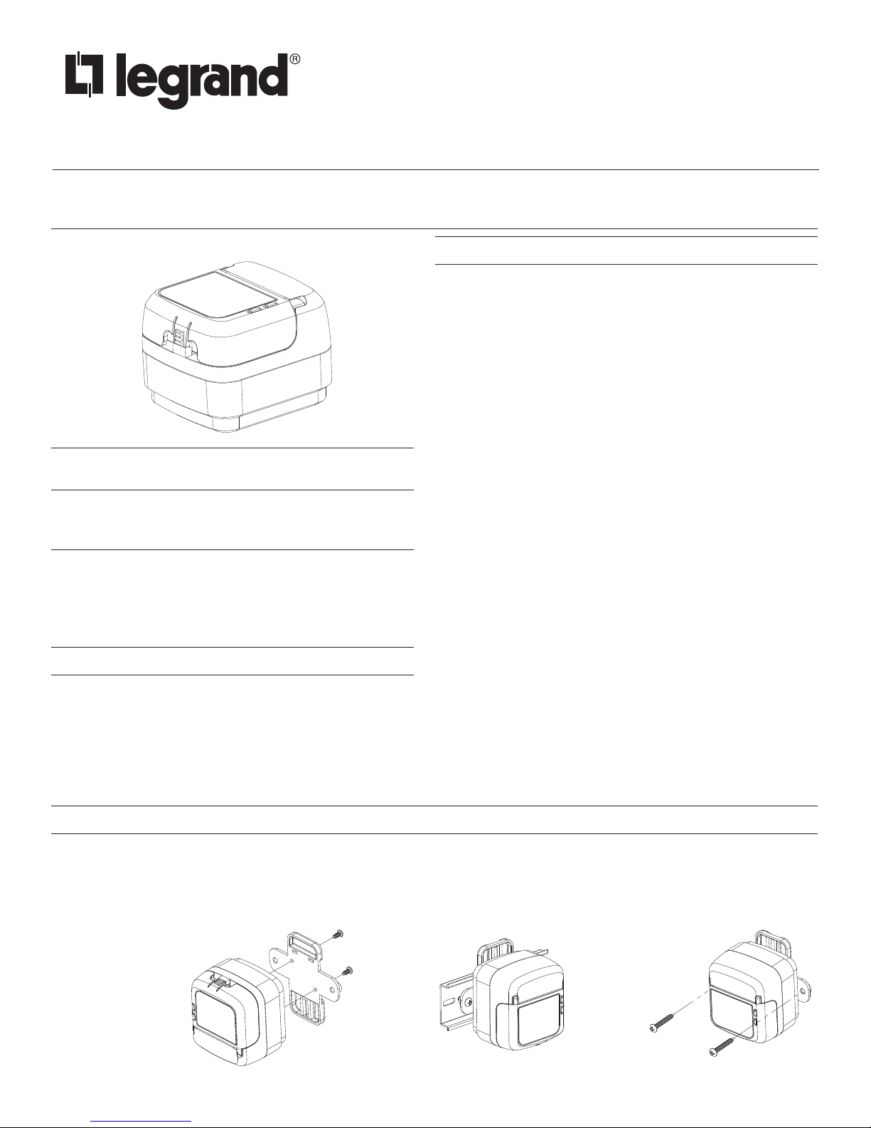
Attach DIN rail clip
MOUNTING AND INSTALLATION
Option 1: Attach to DIN rail
Option 2: Mount to wall

Attach the LMRJ Local Network Cable
WIRING TO THE DLM LOCAL NETWORK
The DLM local network uses free topology low voltage wiring. The LMBC-600 can connect anywhere on the DLM local network using
LMRJ cables.
Use a Wattstopper LMRJ series cable or a Cat5e patch cable to connect the LMBC-600 to one of the RJ-45 jacks on any of the DLM
local network devices. When connected to a powered DLM local network the red Transmit LED blinks rapidly. The red Config LED blinks
at the same rate as the other DLM local network devices.
WARNING: Connect the LMBC-600 RJ-45 jack only to DLM lighting control devices. Do not connect Ethernet to the LMBC-600 RJ-45 jack.
CAUTION: TO CONNECT A
COMPUTER TO THE DLM LOCAL
NETWORK USE THE LMCI-100.
NEVER CONNECT THE DLM LOCAL
NETWORK TO AN ETHERNET PORT
– IT MAY DAMAGE COMPUTERS AND
OTHER CONNECTED EQUIPMENT.
Switch
Occupancy
Sensor
Segment Manager
To
or BAS
LMRJ Cables
LMBC-600
Wireless
Network Bridge
LED INDICATORS
The bridge has two LED indicators visible when the top cover is closed or open
Blue LED
• Blinking – network traffic associated with a border router
• Solid – device is active but not connected to a border router
Network Switch
Room
Controller
(LMRC-112)
Line
Voltage
Line Voltage
Class 1 Dimming
(Class 2 also available)
LMBR-600
Border Router
Load
Examples
(any relay)
Switched
A
Switched with
0-10 Volt control
B
B
Dimming Ballast
LED Driver, etc.
etc.
Red LED
• Blinking – DLM Local network IRB traffic
The following information is intended for use by a Wattstopper authorized start-up technician.
IMPORTANT: Ensure all border routers are installed and powered off (LMRJ unplugged or breaker off) before installing wireless bridges.
For multi story installations, please follow the steps below for each floor.
1. Using a Wattstopper LMRJ Cat5e cable, connect the wireless bridge by plugging the Cat5e cable into an available RJ45 port on
both the bridge and any room controller inside the space or zone to be networked. Once connected to the room controller, the
bridge will power on.
2. After power up sequence(less than 30 seconds), a solid BLUE led indicates the wireless radios are active and searching for border
routers. The BLUE led will remain solid until it has associated with a border router(LMBR-600).
3. Power on all border routers installed in the space or on the individual floor
4. Bridges will automatically discover and join the panID of available border routers. Once this happens, the BLUE led will begin to
blink periodically.
5. Confirm that all wireless bridges are powered on with the BLUE led blinking. Once verified the bridge installation for the area or
floor is complete.
6. Important: For Multi-story deployments, it is recommended that all border routers be powered off to avoid bridges connecting to
border routers on different floors. This method ensures more robust wireless communication between wireless nodes and easier
system startup and management.
7. When all floors have been installed per the steps 1-6, the system is ready to be commissioned by a remote or on-site authorized
Wattstopper Startup technician.
LMBC-600 START-UP PROCESS
2
 Loading...