

LEGRAND LEXIC 037 25 Quick Start Manual
+
+
+
??
25°C
P
2000 W 2000 W
1000 VA1000 VA
2000 W
1000 VA1000 VA
Ø 38 mm
+
Ø 26 mm
Max.
N0064A31/08
TM
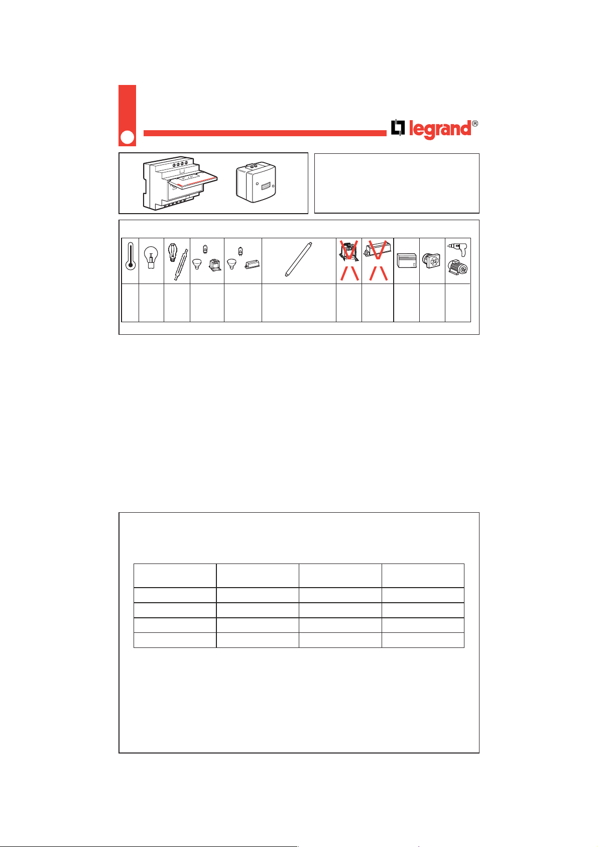
Interrupteur crépusculaire
037 25
Les valeurs de ce tableau sont à diminuer de 20 % par tranche de 10 °C au-dessus de 25 °C.
Caractéristiques techniques
Principe
Cet appareil commande automatiquement un
éclairage ou autre charge suivant un seuil de
luminosité déterminée.
Pour éviter des basculements intempestifs, la sortie
est commutée 5 secondes après la détection.
2000 VA,
compensé série
300 VA,
compensé parallèle
à 45 µF
2
Nombre de tubes admis en fluorescence.
- Alimentation : 230/240 V
~
- 50-60 Hz
- Contact : 10A - 250 V
~
µ - Cos φ =1
- Sensibilité 0,5 à 2000 lux
- Capacité des bornes : 2 x 1,5 mm
2
- Température de stockage et d’utilisation : -25 °C à +60 °C
- Diamètre des tubes et câbles admissibles : de 4 à 15 mm pour cellule (IP 55 - IK 07)
- Temps de réponse du relais aux changements de luminosité : 5 secondes environ.
Caractéristiques techniques (suite)
Tube Non compensé Compensé série Compensé parallèle
Ø38 - 65 W 18 30 4
Ø38 - 40 W 28 50 7
Ø26 - 58 W 20 35 5
Ø26 - 36 W 30 55 8
LEXIC
L
N
D
C
B
A
3
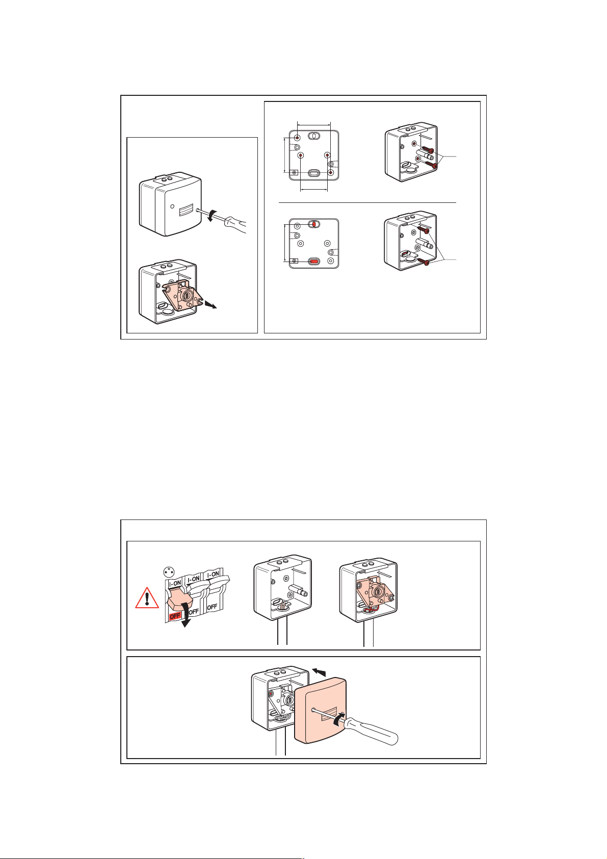
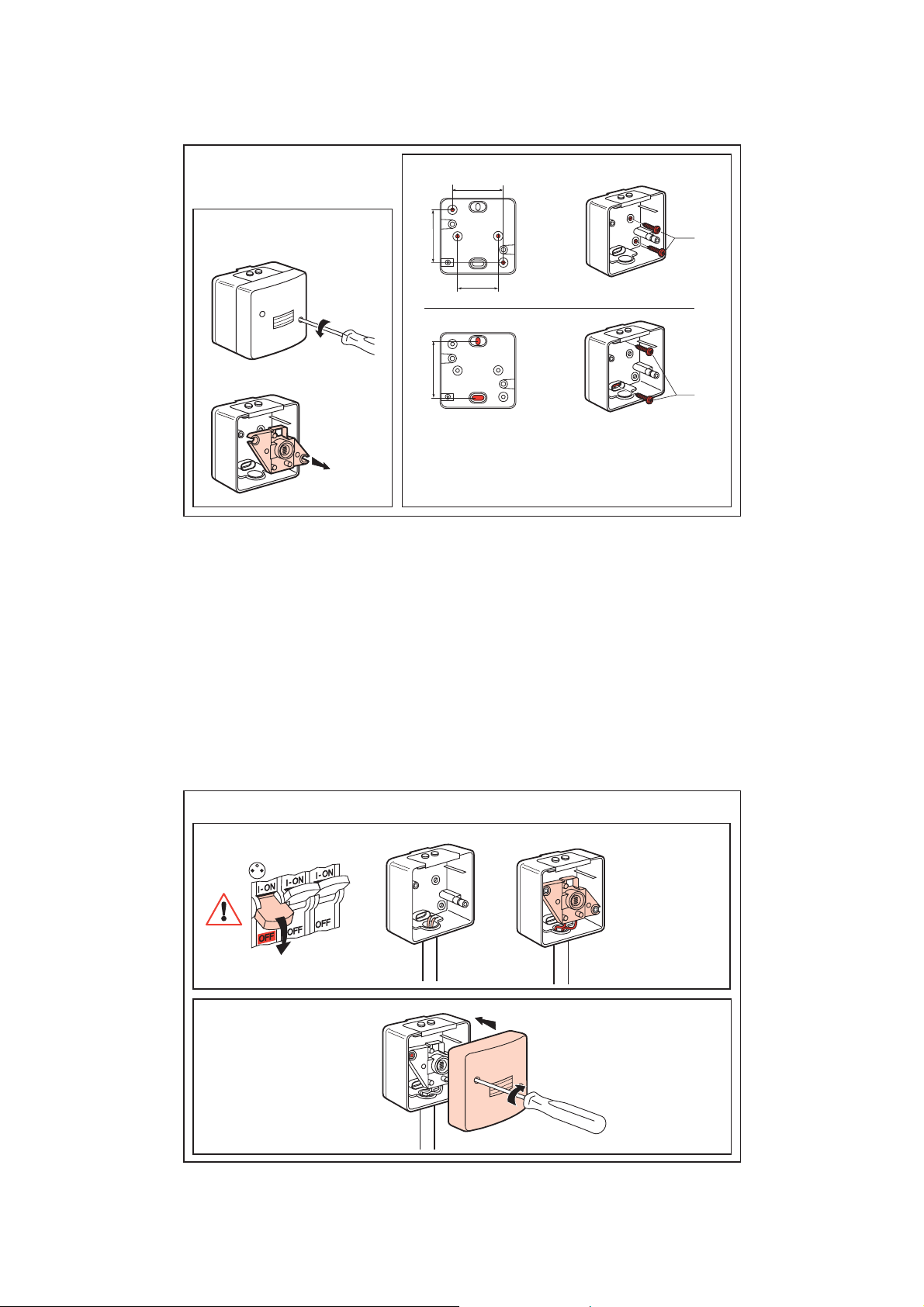
Cellule photoélectrique
Démontage
Ø 4
48
48
38
Ø 4
52
IP 55-5
Fixation
쐃
쐇
La cellule doit être montée verticalement, câblage de préférence par
le bas pour assurer l’étanchéité. La cellule ne doit pas être placée
face aux lampes commandées, face à un éclairage public, près d’un
lieu de stationnement et de passage.
4
Cellule photoélectrique (suite)
Raccordement
Remontage
쐃
쐇
쐃
쐇
Longueur maxi : 50 m
(1,52) entre la cellule
et l’inter crépusculaire.
5
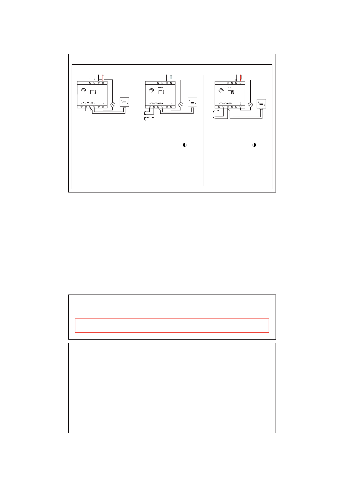
Ensemble inter crépusculaire et cellule
LUX
EF
NL
ABCD
10A
50 m maxi.
10A
250V~
LUX
EF
NL
ABCD
10A
EM
AM
50 m maxi.
10A
250V~
LUX
EF
NL
ABCD
10A
EM
AM
50 m maxi.
10A
250V~
Raccordement
SCHEMA A
Programme 1
Fonctionnement normal :
- court-circuiter les bornes B-C.
La lumière s’allume à la
tombée de la nuit et s’éteint
quand il fait jour.
Programme 2
Fonctionnement inverse :
- court-circuiter les bornes B-C.
- court-circuiter les bornes E-F.
La charge est alimentée quand
il fait jour et coupée quand il
fait nuit.
SCHEMA B
Programme 3
Fonctionnement en rallumage
automatique :
Placer le commutateur sur
- après un allumage automatique, la
nuit étant tombée, le poussoir (EM)
permet d’éteindre manuellement.
Le rallumage sera automatique le
lendemain soir
- le poussoir (AM) est facultatif : il
permet d’allumer manuellement quand
il fait nuit.
SCHEMA C
Programme 4
Fonctionnement en extinction
automatique :
Placer le commutateur sur
- le poussoir (AM) permet d’allumer
manuellement quand il fait nuit.
L’extinction sera automatique dès que
le jour sera suffisant.
- le poussoir (EM) est facultatif, il
permet d’éteindre manuellement sans
attendre le basculement automatique.
6
Ensemble inter crépusculaire et cellule (suite)
Réglages
Raccordement (suite)
Attention : le non respect des schémas de branchements est destructif pour l’appareil, notamment le fait de
raccorder le secteur sur les bornes A, B, C, D, E, F.
Interrupteur crépusculaire modulaire (préréglé à 20 lux)
Régler le seuil de luminosité par action sur le potentiomètre.
+
+
+
??
25°C
P
2000 W 2000 W
1000 VA1000 VA
2000 W
1000 VA1000 VA
Ø 38 mm
+
Ø 26 mm
Max.
Schemerschakelaar
037 25
De waarden in de tabel moeten verminderd worden met 20 % per 10 °C boven 25 °C
.
Technische gegevens
Principe
Dit apparaat bestuurt automatisch een verlichting of
andere belasting, overeenkomstig een vastgestelde
lichtsterktedrempel.
Om ongewenste schakelingen te voorkomen zal de
uitgang pas 5 sec. na detectie worden omgeschakeld.
7
2000 VA,
serie gecompenseerd
300 VA,
parallel gecompenseerd
met 45 µF
TM
8
Aantal toegelaten TL-buizen.
- Voeding : 230/240 V
~
- 50-60 Hz
- Contact : 10A - 250 V
~
µ - Cos φ = 1
- Gevoeligheid 0,5 tot 2000 lux
- Klemmencapaciteit : 2 x 1,5 mm
2
- Opslag- en bedrijfstemperatuur : -25 °C tot +60 °C
- Doorsnede van de toelaatbare buizen en kabels : 4 tot 15 mm voor fotocel (IP 55 - IK 07)
- Reactietijd van het relais op lichtsterkteveranderingen : ong. 5 sec.
Technische gegevens (vervolg)
Buis Nier gecompenseerd Serie gecompenseerd Parallel gecompenseerd
Ø38 - 65 W 18 30 4
Ø38 - 40 W 28 50 7
Ø26 - 58 W 20 35 5
Ø26 - 36 W 30 55 8
LEXIC
L
N
D
C
B
A

9
Fotocel
Demonteren
Ø 4
48
48
38
Ø 4
52
IP 55-5
Bevestigen
쐃
쐇
De fotocel moet vertikaal gemonteerd worden, en bij voorkeur met de
bedrading aan de onderzijde om een correcte dichtheid te verkrijgen.
De fotocel mag nooit tegenover de bediende lampen of een openbare
verlichting worden geplaatst, noch in de buurt van een parkeerplaats
of voorbijgaand verkeer.
10
Fotocel (vervolg)
Aansluiten
Monteren
Max. lengte : 50m (1,52)
tussen fotocel en
lichtgevoelige schakelaar.
쐃
쐇
쐃
쐇

11
Schemerschakelaar/fotocel-unit
Aansluiten
SCHEMA A
Programma 1
Normale werking:
- kortsluiting van de klemmen B-C.
De verlichting wordt ingeschakeld
bij donker en uitgeschakeld bij
daglicht.
Programma 2
Tegenovergestelde werking:
- kortsluiting van de klemmen B-C
- kortsluiting van de klemmen E-F
De belasting wordt gevoed bij
daglicht en verbroken bij donker.
SCHEMA B
Programma 3
Werking met automatische
herinschakeling :
Zet de schakelaar op
- na automatische inschakeling bij
donker, kan met de hand worden
uitgeschakeld met behulp van
drukknop (EM).
De verlichting wordt nu de volgende
avond opnieuw automatisch
ingeschakeld.
- de drukknop (AM) is facultatief. Deze
is bestemd voor handbediende
inschakeling bij donker.
SCHEMA C
Programma 4
Werking met automatische
uitschakelig
Zet de schakelaar op
- de drukknop (AM) is bestemd voor
handbediende inschakeling wanneer
het donker wordt.
De uitschakeling vindt automatisch
plaats zodra er voldoende daglicht is.
- De drukknop (EM) is facultatief.
Hiermee is handbediende
uitschakeling mogelijk zonder op
automatische omschakeling te
wachten.
LUX
EF
NL
ABCD
10A
50 m maxi.
10A
250V~
LUX
EF
NL
ABCD
10A
EM
AM
50 m maxi.
10A
250V~
LUX
EF
NL
ABCD
10A
EM
AM
50 m maxi.
10A
250V~
12
Schemerschakelaar/fotocel-unit (vervolg)
Instellen
Aansluiten (vervolg)
Opgelet : het niet naleven van de aansluitschema's kan leiden tot ernstige beschadiging van het apparaat, met
name bij aansluiting van de netstroom op klemmen A, B, C, D, E, F.
Modulaire lichtgevoelige schakelaar (vooringesteld op 20 lux)
Stel met de potentiometer de lichtsterktedrempel in.

13
+
+
+
??
25°C
P
2000 W 2000 W
1000 VA1000 VA
2000 W
1000 VA1000 VA
Ø 38 mm
+
Ø 26 mm
Max.
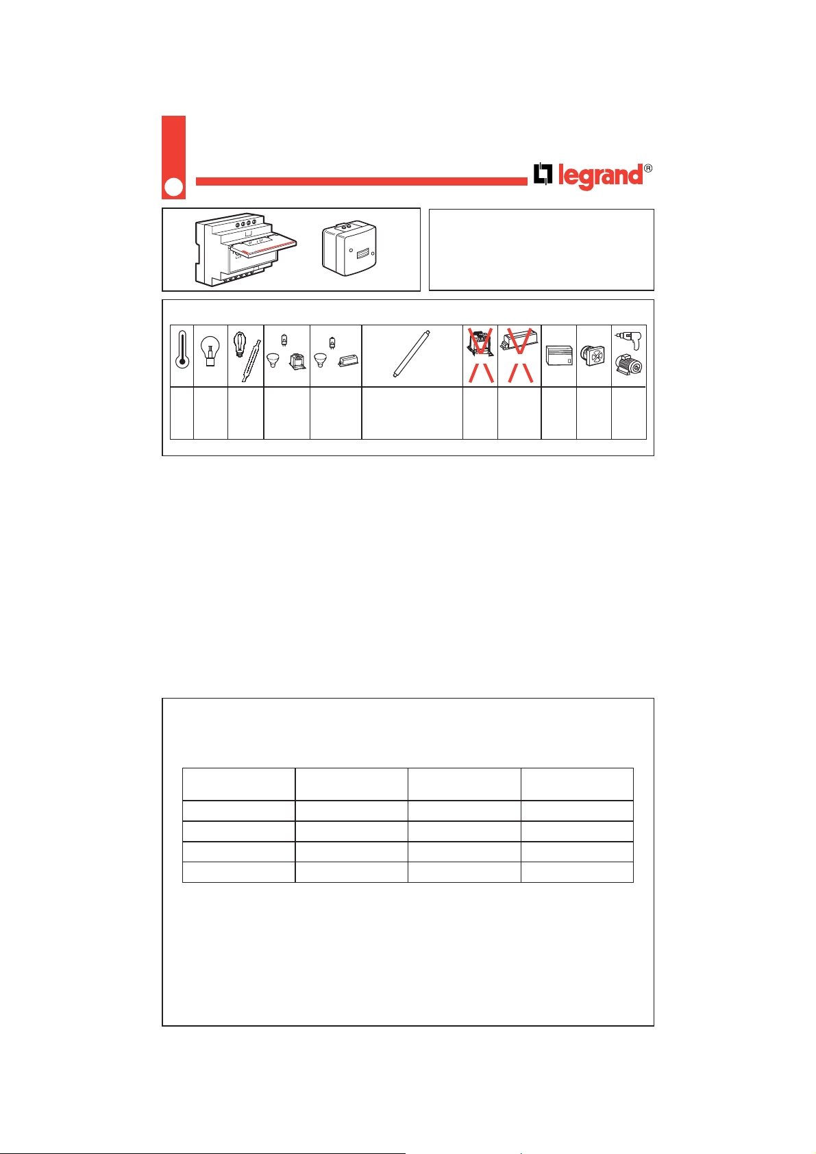
Light sensitive switch
037 25
The values given in this list must be reduced by 20% for each 10 °C above 25 °C.
Technical specifications
Principle
This device controls lighting, or another load,
automatically, according to a set level of light.
To avoid unwanted switching, the output switches
5 seconds after detection.
2000 VA,
series compensated
300 VA,
parallel compensated
at 45 µF
TM
14
Number of fluorescent tubes permissible.
- Power supply : 230/240 V AC - 50/60 Hz
- Switch : 10A - 250 V AC µ - Cos
φ = 1
- Sensitivity 0,5 to 2000 lux
- Terminal capacity : 2 x 1.5 mm
2
- Storage and operating temperature range : -25 °C to +60 °C
- Diameter of conduit on cable entring : 4 to 15 mm (IP 55 - IK 07)
- Reaction time of relay to light level changes is about 5 seconds
Technical specifications (continued)
Tube Uncompensated Series compensation Parallel compensation
Ø38 - 65 W 18 30 4
Ø38 - 40 W 28 50 7
Ø26 - 58 W 20 35 5
Ø26 - 36 W 30 55 8
LEXIC
L
N
D
C
B
A
15
Photocell
Disassembly
Ø 4
48
48
38
Ø 4
52
IP 55-5
Fastening
쐃
쐇
Photocell is to be installed vertically, and preferably cabled from below
to ensure weatherproofing. The photocell should not to be located
facing the controlled lights or any street lighting, or near to car parks
or roadways.
16
Photocell (continued)
Connection
Refitting
Maximum length between
photocell and light sensitive
switch is 50 m (1,52).
쐃
쐇
쐃
쐇

17
Light sensitive switch and photocell assembly
Connection
DIAGRAM A
Programme 1
Normal operation :
- link terminals B-C.
The lamp is on at nightfall and
off at daybreak.
Programme 2
Reverse operation :
- link terminals B-C
- link terminals E-F
The load is powerel during
daylight, and is switched off
after dark.
DIAGRAM B
Programme 3
Automatic operation to on with
manuel off :
Set the selection switch to
- following automatic switch on, a
manual switch off is possible by
pressing the (EM) button.
The unit will function automatically
at the next nightfall.
The button AM (if installed) : per mits
manual on.
DIAGRAM C
Programme 4
Automatic operation to off with
manuel on :
Set the selector switch to
- following on automatic switch off a
manuel switch on is possible by
pressing the button (AM).
Automatic extinction is carried-out
as soon as daylight is sufficient.
- the button EM (if installed) per mits
manuel off.
LUX
EF
NL
ABCD
10A
50 m maxi.
10A
250V~
LUX
EF
NL
ABCD
10A
EM
AM
50 m maxi.
10A
250V~
LUX
EF
NL
ABCD
10A
EM
AM
50 m maxi.
10A
250V~
18
Light sensitive switch and photocell assembly (continued)
Setting
Connection (continued)
Attention : fail to observe the wiring information may result in domage to the product. It is important not to connect
the mains supply to the terminals A, B, C, D, E, F.
Modular light sensitive switch (pre-set to 20 lux)
Set light level with the potentiometer.
 Loading...