

LEGRAND LEGD365 061, LEGD365 062, LEGD365 066, LEGD365 064, LEGD365 068 Installation Instructions Manual
...
Installation instructions for entry kits using entry panels
LEGD365 061/062/064/066/068/069/060
Description
Components required for 1 to multi apartment kits
Entry Panel
(Made up in 2 button increments
to suit number of call buttons required)
1650
Ground
1600
85
219
Ground
Series 7 Handset
Surface Box
mild steel or
3CR12 stainless steel
with light grey epoxy coating
(Select size according to
configuration of entry panel)
Power supply unit
CP13E/12V
alternatively connect to
12V DC battery of gate motor
System operation
When a call button on the outside entry panel is pressed all the handsets connected to this call button will ring. A
maximum of four handsets can be connected to one call button. There will be a simultaneous ring at the entry panel to
confirm the ringing at the handset(s ). When lifting the handset off its cradle inside, communication between the
handset and entry panel can take place. If at the same time any other handset is lifted off its cradle, there will be
common communication with the first handset and the entry panel. At any time any handset in the system can be lifted
off its cradle and there will be a communication link with the entry panel. This is regardless of whether this handset has
been called from the entry panel. The speech volume at the handset(s) and entry panel can be set independently.
The entrance door or gate can be operated using the door/gate release pushbutton provided on the handset. A second
pushbutton is provided to operate auxiliary functions such as other features on the entrance gate operator or switch a
light outside the front door or gate. A pushbutton is provided on the entry panel to illuminate the call button label and
improve usability in dark conditions. This latest generation of entry panels, the Series 7, simplifies the installation of the
system, and through improved weatherproofing enhances the long term reliability of the product.
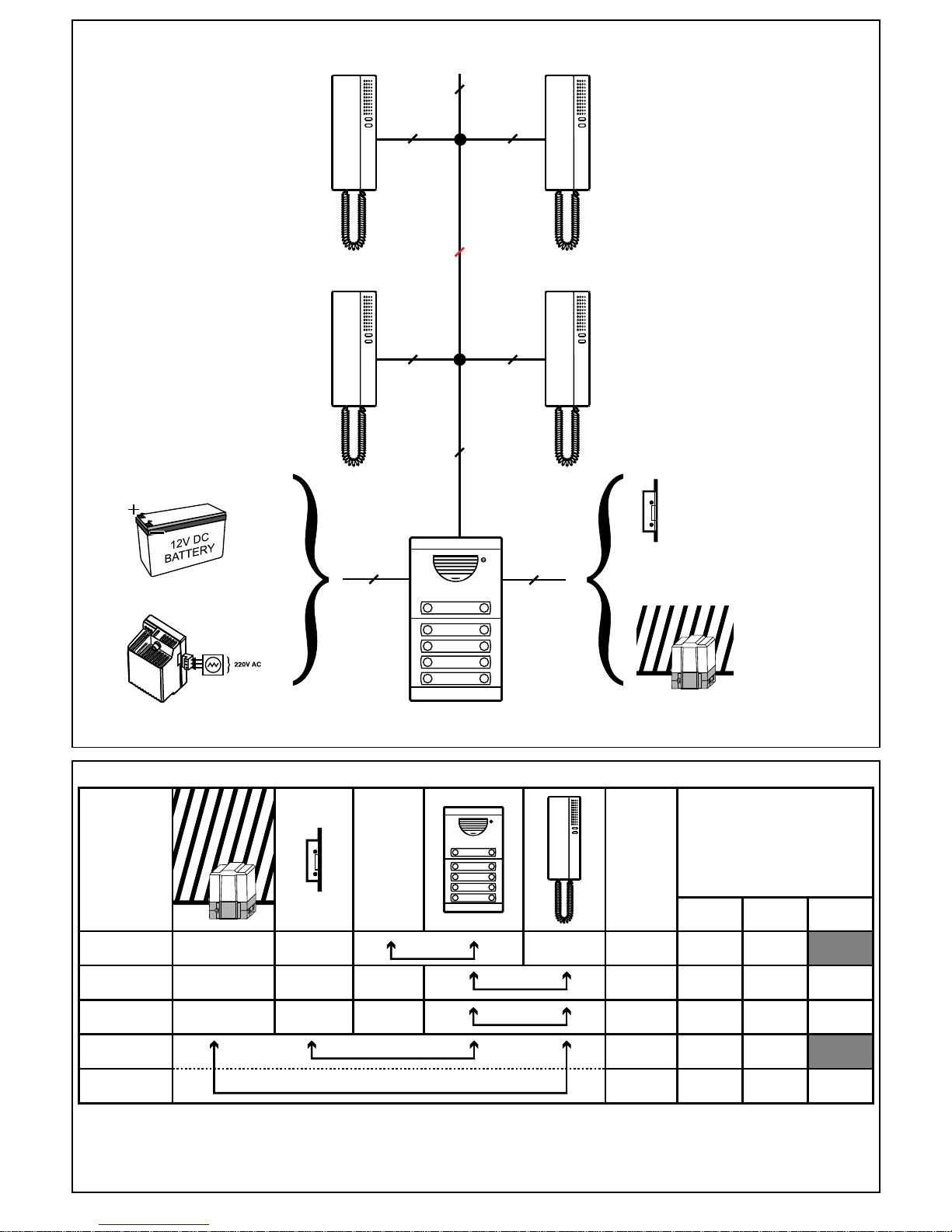
Line diagram for Series 7 entry panel
2
3
†
1+n
2
2
1.5
0.25
0.25
1.5
0.25
2.5
0.25
0.5
2.5
0.25
0.5
2
2
0.5
50 m 100 m 200 m
Min.
Cross-sections (mm²)
Number
of wires
Power
Supply
Connections
9, 10
3, 4, 5
1E, 2
10, 11
2, 3
ALTERNATIVELY
Table of recommended cross-sections
2
4+n
5
2
5
5 5
4+(n-2)
4+(n-4)
OR
12V DC Power Supply only.
Door strike
or
Gate release
CP13E/12V
Power supply
Wiring diagram for Series 7 entry panel
NOTES
1 - A door strike can only be connected directly to the entry panel as shown, if an AC supply is powering the unit.
2 - If the cable distance is greater than 100m a ring amplifier (CP112) is recommended on the call line circuit
†
n = number of call buttons
SITUATION:
1. The gate / door release is used to operate a gate motor and the power supply to the
system is either 12V DC or AC.
2. The gate / door release is used to operate a low current door strike and the power
supply to the system is strictly 12V AC.
See note 1
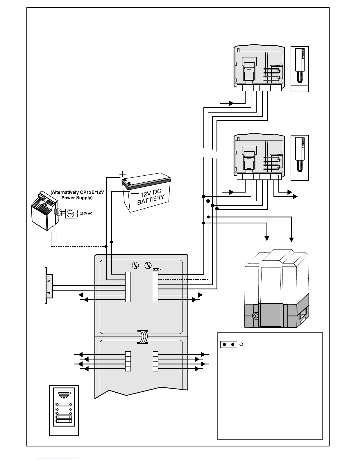
Wiring diagram for Series 7 entry panel
Series 7
2
3 4 51EPP
1Z
2
3 4 5
1EPP1Z
Pn
P1
9
10
10
11
3
4
5
9
10
10
11
2
3
4
5
P
4
P
2
P
3
P
1
P1
P3
P2
P4
3
4
5
P
2
P
4
P
6
P
8
9
10
10
11
P
1
P
3
P
5
P
7
COM TRG
See note 1
See note 2
See note 3
12V DC Power Supply
Note polarity
Series 7 entry panel
Series 7
NOTE 1 Select the chime type in the sound unit.
Left jumper: electronic
NOTE 2 Only connect if operating a door lock and not
a gate motor
NOTE 3 A door strike can only be connected directly to
the entry panel as shown, if an AC supply is powering
the unit.
NOTE 4 p1, p2…pn are the call lines to the
handset(s) in each apartment / house. With an
apartment system each apartment will typically have a
dedicated call line.
P1 = top right hand call button of a call button panel
(viewed facing the front of the panel)
P2 = top left hand call button etc
SITUATION:
1. The gate / door release is used to operate a gate motor and the power supply to the
system is either 12V DC or AC.
2. The gate / door release is used to operate a low current door strike and the power
supply to the system is strictly 12V AC.
See note 4
See note 4 See note 4
Potential free
auxiliary contact
(NO)
 Loading...