

Page 1
0 035 66
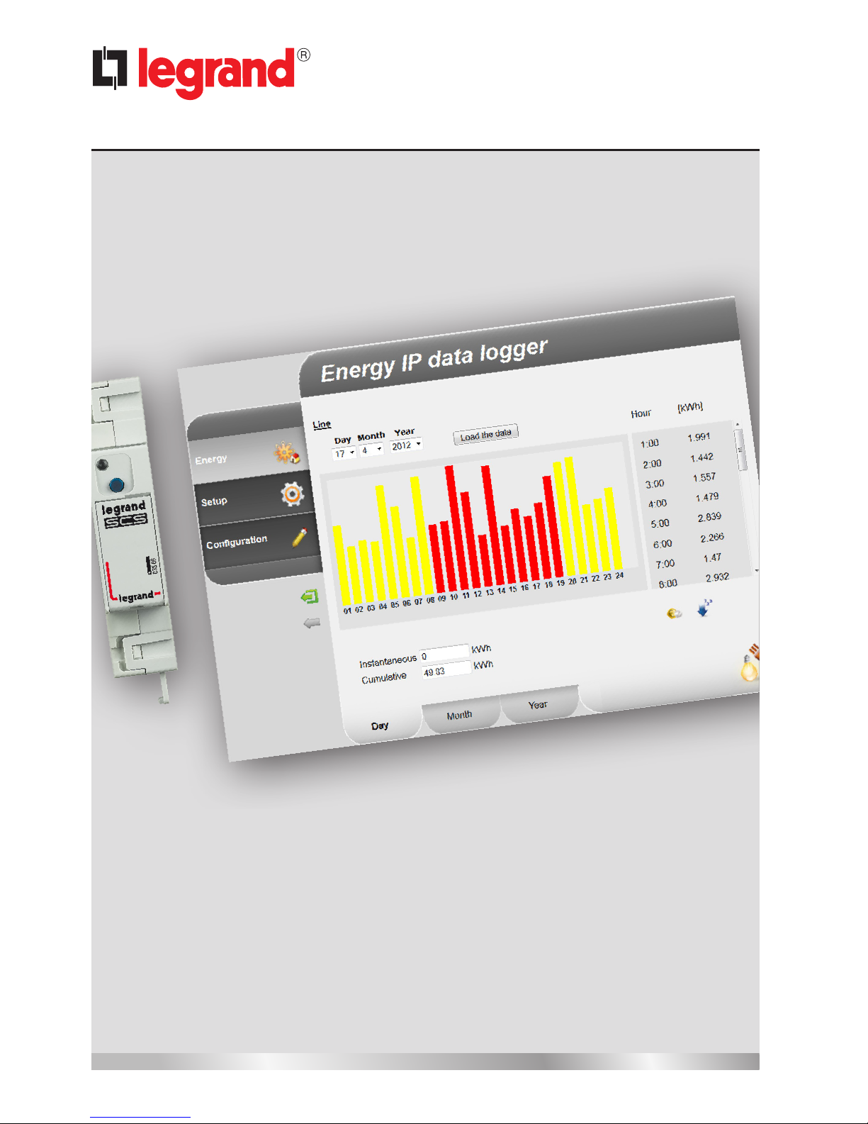
Energy Data Logger
Installer manual
06/12-01 PC
Page 2
2
Page 3

Energy Data Logger
Contents
3
Installer manual
1 Description 4
1.1 Warnings and recommendations 4
1.2 Main functions 4
1.3 Legend 5
2 Connection 6
2.1 Wiring diagrams 6
3 Configuration 7
3.1 Procedure with Windows 2000 or XP operating system 7
3.2 Procedure with Windows Vista or 7 operating system 16
3.3 Procedure for Tablet and Smartphone 22
3.4 Troubleshooting 22
4 Appendix 23
4.1 Technical data 23
Page 4

4
1.1 Warnings and recommendations
Before proceeding with the installation we recommend that you read the content of this manual
very carefully.
The warranty will automatically become void in case of negligence, improper use, and tampering
by unauthorised personnel.
1 Description
1.2 Main functions
The SCS device saves the consumption values in separate energy lines. These lines can be both
electric, by connecting Bus meters with 3 inputs for toroids, item F520, or a load management
central unit, item F521, and non-electric, by connecting pulse counter interfaces, item 3522. The
total number of lines managed cannot exceed 10.
Page 5
Energy Data Logger
5
Installer manual
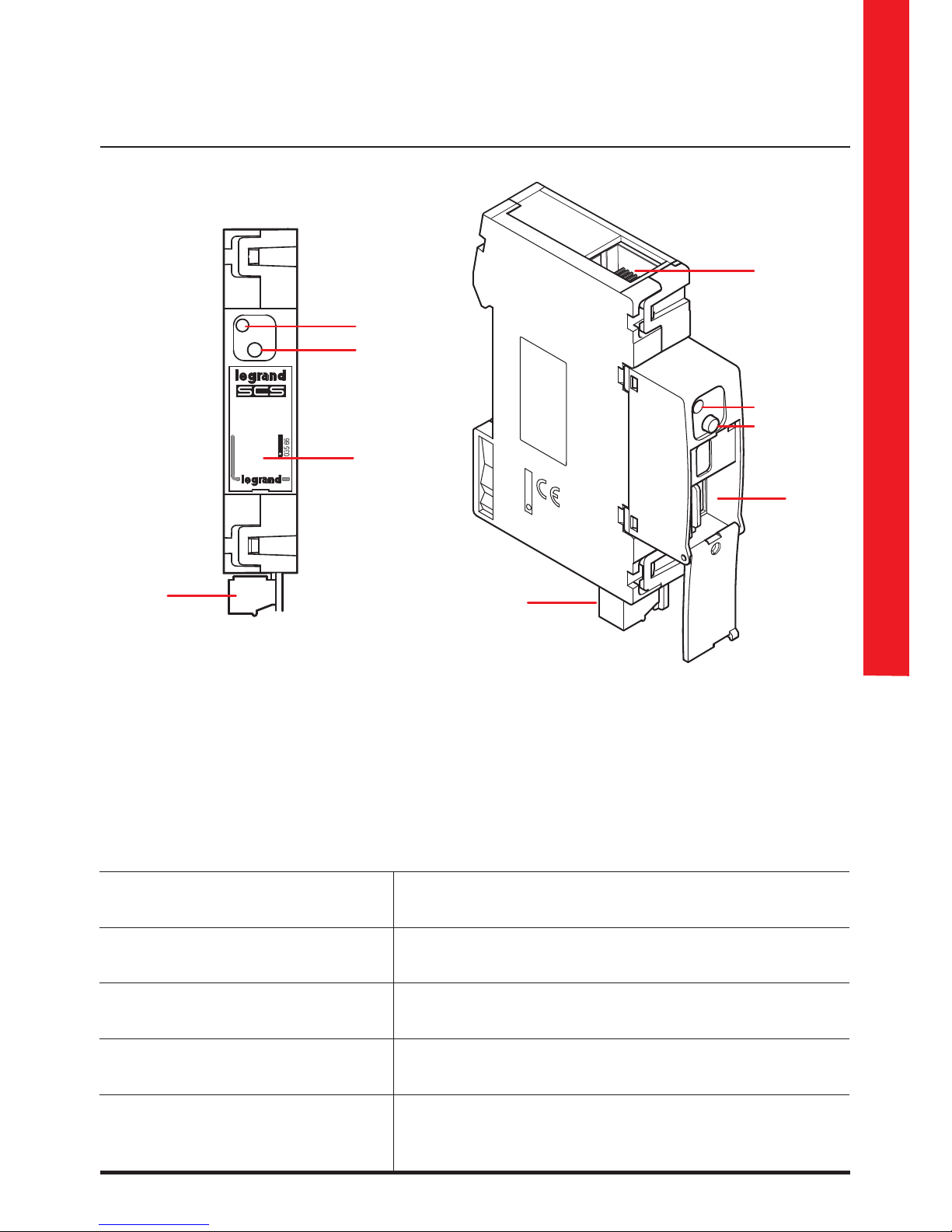
1 - User interface LED: see table
2 - MicroSD memory card slot (optional)
3 - Connection to the SCS BUS
4 - Ethernet connection
5 - Reset key:
– press and hold for 10 seconds to restart the Energy Data Logger;
– press and hold for 20 seconds to restart the Energy Data Logger , and set the dynamic
selection of the IP address.
1.3 Legend
User interface LEDs table
Red LED
flashing slowly and regularly:
no network found;
waiting for an address to be assigned.
Green LED
flashing slowly and regularly:
device waiting to be configured.
Green LED
flashing quickly and regularly:
time on the device not configured.
Green LED
flashing slowly and irregularly:
device working and configured.
Red-green LED
flashing quickly:
IP or microSD configuration error.
Reset, check the configuration, and the microSD
memory card model.
4
2
1
2
3
1
5
5
3
Page 6

6
Check that your PC is set for automatic acquisition of the IP address (network parameters);
then select the Energy Data Logger device among the network resources.
2 Connection
Diagram with direct or crossover cable
2.1 Wiring diagrams
To put the device into operation, this must be connected following the diagrams below.
Diagram with switch
BUS
BUS
Switch / router
Page 7
Energy Data Logger
7
Installer manual
3.1 Procedure with Windows 2000 or XP operating system
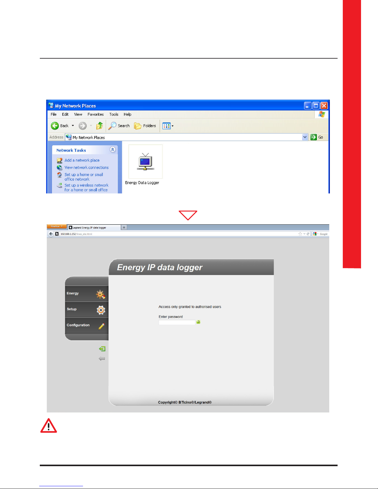
If the connection is correct, it will be possible to display the device in the My Network Places
window, with the name “Energy Data Logger”.
3 Configuration
The Web pages can be accessed with two authority levels: “user" and as “administrator”.
In addition to having access to the same pages as the user, the administrator can also
access the “Configuration” function and define some Data Logger parameters. Ask your
installer for the access passwords, if this has not already been provided.
To learn how to navigate through the web pages refer to the user manual.
Double click on the icon to open the configuration WEB page.
Page 8
8
1
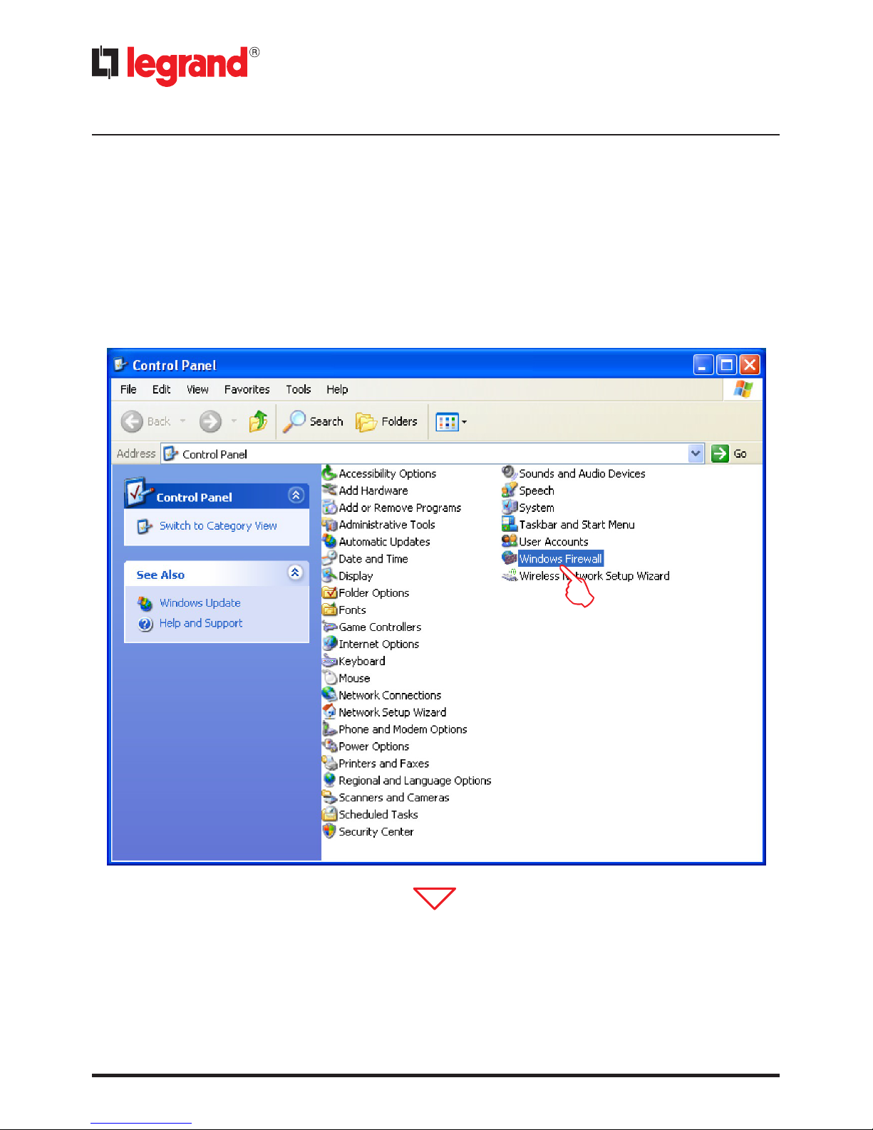
From the Start / Control panel menu
1 - Click "Windows Firewall".
If the device is not automatically recognised by the PC, follow the instructions below. To access
the configuration page, and display the device IP address, the following parameters must be set:
3 Configuration
Page 9

Energy Data Logger
9
Installer manual
4
2 - Select “Exceptions”.
3 - Enable "UPnP Framework".
3
2
From the
Start / Control panel menu
4 - Click “Add or Remove
Programs”.
Page 10

10
5 - Click “Add/Remove
Windows components”.
5
6 - Enable “Networking
services”
7 - Click “Details”.
6
7
3 Configuration
Page 11

Energy Data Logger
11
Installer manual
8 - Enable "Internet Gateway
Device Discovery and
Control Client".
9 - Enable "UPnP User
Interface".
10 - Click.
8
9
10
11
11 - Click.
Page 12

12
12 - Click “Finish”.
12
From the Start / Control panel menu
13 - Click “Administrative Tools”.
13
3 Configuration
Page 13

Energy Data Logger
13
Installer manual
14 - Click “Services”.
14
15 - Set Automatic Startup Type for “Universal Plug and Play Device Host”.
15
Page 14

14
18
16 - Click “Start”
17 - Click.
16
17
18 - Set Automatic Startup Type for “SSDP Discovery Service”.
3 Configuration
Page 15

Energy Data Logger
15
Installer manual
19 - Click “Start”.
20 - Click.
19
20
Page 16

16
3.2 Procedure with Windows Vista or 7 operating system
If the connection is correct, it will be possible to display the device in the My Network Places
window, with the name “Energy Data Logger”.
3 Configuration
The Web pages can be accessed with two authority levels: “user" and as “administrator”.
In addition to having access to the same pages as the user, the administrator can also
access the “Configuration” function and define some Data Logger parameters. Ask your
installer for the access passwords, if this has not already been provided.
To learn how to navigate through the web pages refer to the user manual.
Double click on the icon to open the configuration WEB page.
Page 17

Energy Data Logger
17
Installer manual
If the device is not automatically recognised by the PC, follow the instructions below. To access
the configuration page, and display the device IP address, the following parameters must be set:
From the
Start / Control panel menu
1 - Click "Windows Firewall".
1
2 - Click “Allow a program or
feature through Windows
Firewall”.
2
3 - Enable both Public
and Private “Network
Discovery”.
3 3
Page 18

18
3 Configuration
From the
Start / Control panel menu
4 - Click “Network and Sharing
Center”
5 - Click "Change advanced
sharing settings"
5
6
6 - Turn on “Network
discovery”
4
Page 19

Energy Data Logger
19
Installer manual
From the
Start / Control panel menu
7 - Click “Administrative Tools”
7
8 - Click “Services”.
8
Page 20

20
3 Configuration
9 - Set Automatic Startup Type for item "UPnP Device Host" and ensure that it has actually been
enabled.
9
10 - Click “Start”.
11 - Click.
10
11
Page 21

Energy Data Logger
21
Installer manual
12 - Set Automatic Startup Type for item “SSDP Discovery” and ensure that it has actually been
enabled.
12
13 - Click “Start”.
14 - Click.
13
14
Page 22

22
3 Configuration
3.3 Procedure for Tablet and Smartphone
If viewing the pages using a Tablet or a Smartphone, it is recommend to set fixed IP and IP mask;
in alternative, use an application for the identification of UPnP devices.
3.4 Troubleshooting
Problem Solution
When directly connected to the
PC, the device cannot be displayed
among the system resources.
Power the device by pressing and holding down the reset
key until the red LED starts flashing: initialisation of the
device will start, and the following parameters will be set:
IP address: 192.168.1.5
IP Mask: 255.255.255.0
It will now be possible to connect to the device and
reconfigure the parameters.
The device web pages are not
correctly displayed
1. In the browser parameters enable "Compatibility
mode";
2. Delete the browser history, including, including
"Temporary files/cache”.
Internet Explorer 7 (on Windows XP) and 9 (on windows 7)
Google Chrome 19.0.1084.56
Safari 5.1.7
Mozilla Firefox 12
Opera 11.64
Note: the device has been tested with the following browser versions:
Page 23

Energy Data Logger
23
Installer manual
4 Appendix
Power supply from BUS 18 – 27 Vdc
Assorbimento 30 mA (max)
Operating temperature 5 – 45 °C
4.1 Technical data
Page 24

Legrand reserves at any time the right to modify the contents of this booklet and to communicate in any form and
modality, the changes brought to the same.
World Headquarters and
International Department
87045 LIMOGES CEDEX FRANCE
: 33 5 55 06 87 87
Fax : 33 5 55 06 74 55
www.legrand.com
 Loading...