

LEGRAND Evolution ATCFF, Evolution 6STC, Evolution, Evolution 6CFFTC, Evolution 15FFHA Installation Instructions Manual
...Page 1
Wiremold electrical systems conform to and should be properly
grounded in compliance with requirements of the current National
Electrical Code or codes administered by local authorities.
All electrical products may present a possible shock or fire
hazard if improperly installed or used. Wiremold electrical products may
bear the mark as UL Listed and/or Classified and should
be installed in conformance with current local and/or the National
Electrical Code.
Evolution™Series
6" Furniture Feed Poke-Thru Devices
I N S T A L L A T I O N I N S T R U C T I O N S
Installation Instruction No.: 1 007 155 R2 – Updated May 2010
Products Covered: 6ATCFF, 6STC, 6CFFTC, 15FFHA, 152CHA, CE6ATCFF
CAUTION DO NOT operate tile stripper, cleaning, or resurfacing equipment over top of covers. This may result in
damage to the surface finish of the product.
Suitable for use in air handling spaces in accordance with Sec. 300-22 (C) of the National Electrical Code.
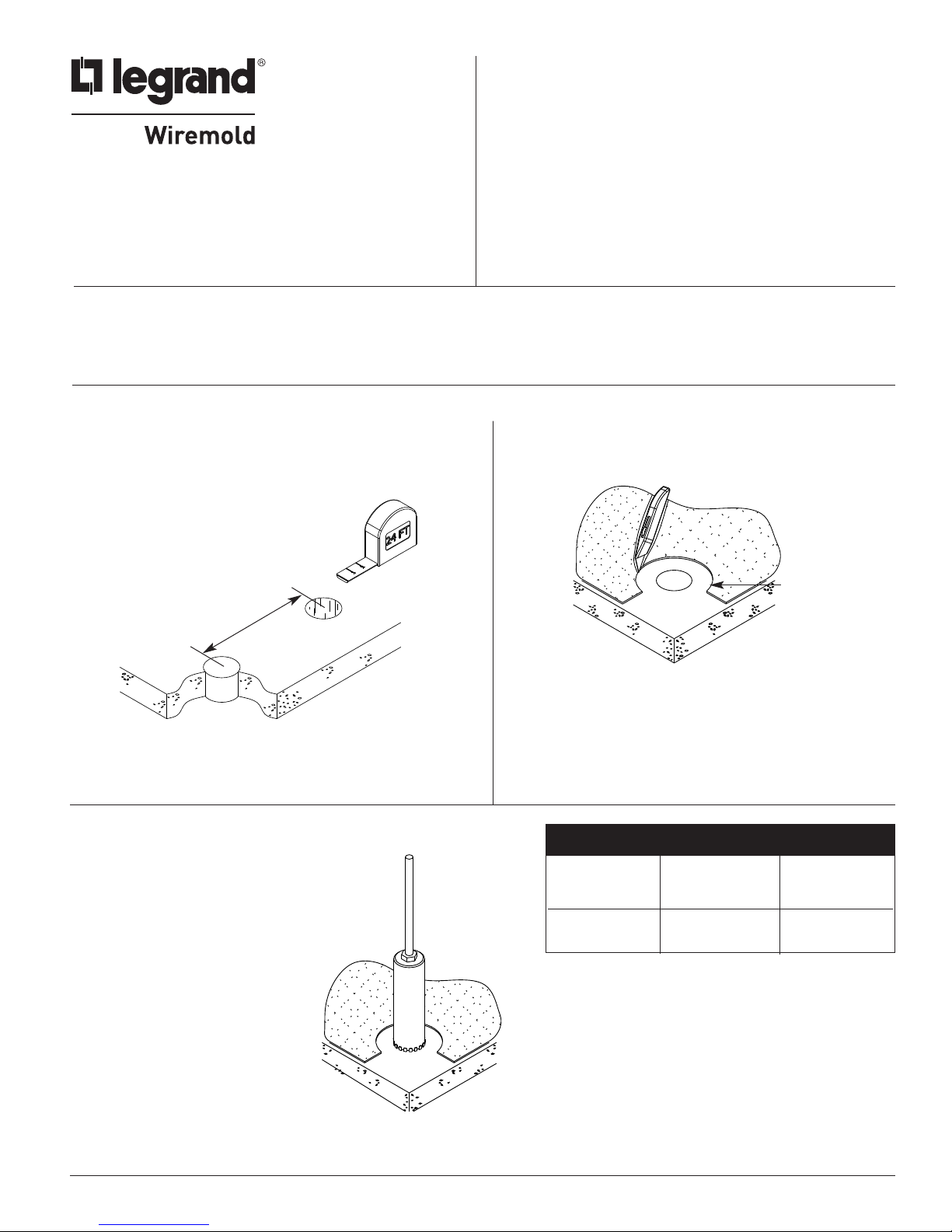
FLOOR PREPARATIONS
Step 1 Layout and locate position of hole(s).
CAUTION: Minimum spacing of 2ft on center and not more than
one device per each 65 square feet of floor area in
each span.
IMPORTANT: Please read all instructions
before beginning.
Step 2 Remove 7 1/4" dia. [166mm] section from
carpet or tile. Use template provided.
24" [610mm] Min
Center – Center
CAUTION: Be certain to locate hole at least 6" [152mm] from any wall or
pillar to leave enough room for Poke-Thru cover assembly.
Step 3 Create core hole according to the
dimensions provided in the chart.
7 1/4"
[166mm]
FLOOR CORE CORE
TYPE SIZE (Min.) SIZE (Max.)
Covered Floors 6" [152mm] 6 1/8" [156mm]
(Carpet, Tile or
Wood)
Bare Concrete 6 1/16" [154mm] 6 1/8" [156mm]
or Terrazzo
1
Page 2
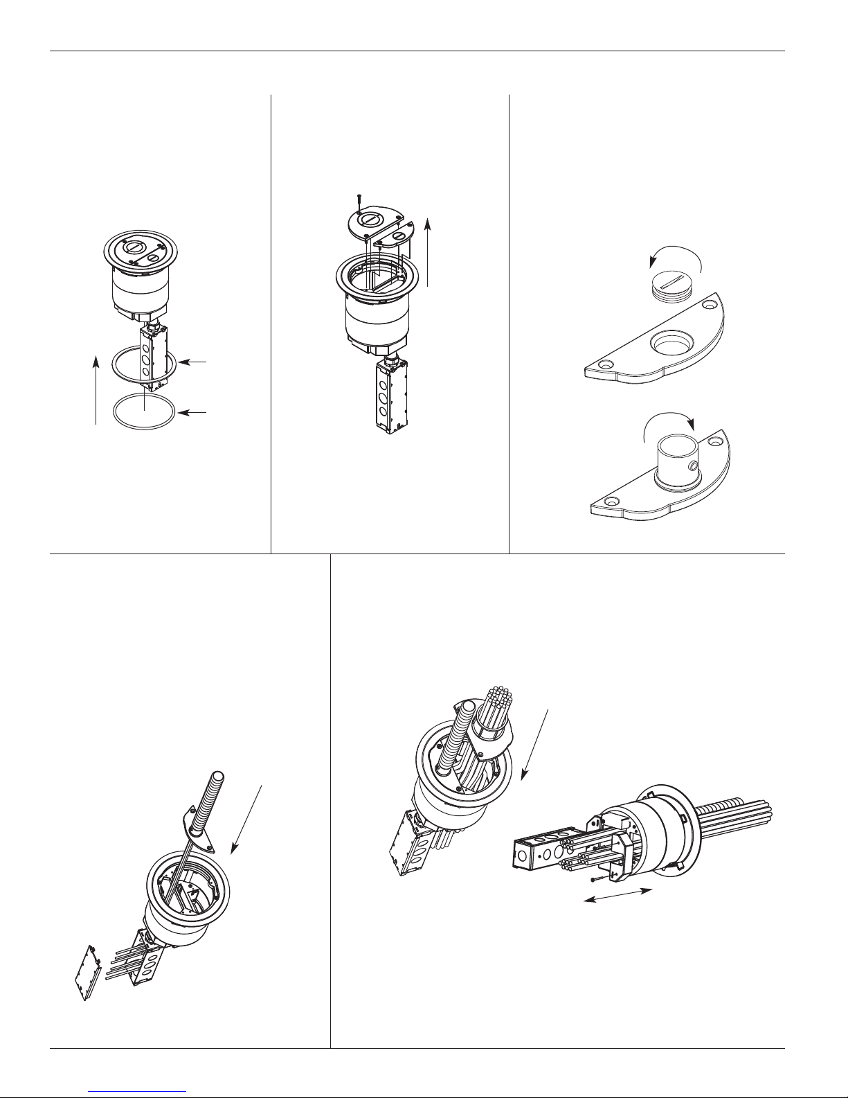
NSTALLING COMPLETE ASSEMBLY
I
Step 1 Place appropriate gasket
around Poke Thru and
slide under flange. Use
flat foam gasket for tile
pplications or use round
a
neoprene gasket for
carpet applications.
ile Gasket
T
Carpet
asket
G
Step 2 Remove cover plates by
removing (5) 8-32 screws.
Step 3 Remove 3/4" plug from small
cover plate by rotating counterclockwise using a large straight
lade screwdriver. Install 3/4"
b
conduit fitting (provided) into
opening on large cover. Repeat
procedure for 2" conduit fitting,
on large cover plate. (provided)
Step 4 Feed 3/4" inch flexible conduit
into 3/4" conduit fitting on cover
plate. Feed power wires through
small compartment and into the
junction box. Make wiring connections in the junction box.
Refer to copper cross section
chart to determine quantity of
wires to pass through each opening. Attach cover to the flange
using (2) 8-32 x 3/8" screws.
Step 5 Feed data wires through larger compartment and through
2" conduit fitting on cover plate. Refer to copper cross
section chart to determine quantity of cables to pass
through each opening. Attach cover to the flange using
(3) 8-32 x 3/8" screws.
NOTE: Splices must be made in junction box.
NOTE: If necessary remove Feed Plates to pull communications wires through
Poke-Thru device. Replace Feed Plates when finished pulling wires.
CAUTION: To maintain fire classification, Feed Plates must be installed.
2
Page 3

Step 6 Orient Poke Thru so that the three channels span across the corrugations of the deck.
Push Poke-Thru into floor.
B BA A
Device openings must
span across deck
CAUTION: Cover must be removed to rotate Poke Thru once it has been installed in the floor.
Step 7 Installation complete.
3
Page 4

NSTALLING STEM ASSEMBLY AND SEPARATE COVER
I
Step 1 Orient Stem Assembly such that the three channels span across the corrugations of the deck.
nsert Stem Assembly into core hole.
I
A A B B
Device openings must
span across deck
CAUTION: Cover must be removed to rotate Poke Thru once it has been installed in the floor.
Step 2 Remove disposable plate and (2) plate clips by removing the 8-32 screws. Install Flange using the
(2) 8-32 x 1/2" Cap Head screws provided with the cover assembly.
4
Page 5

CONFIGURING FEED PLATES
Step 1 Remove cover assembly from Poke Thru by
emoving (2) 8-32 screws and lifting cover off.
r
tep 2 Remove Poke Thru from floor by bending
S
tabs inward and pulling unit up.
Step 3 Remove (4) 8-32 screws and pull off
feed housings.
Step 4 Use (4) 8-32 screws to install new feed plate
or housing.
CAUTION: To maintain fire classification, Feed Plates
must be installed.
5
Page 6

Evolution Series Poke-Thru Devices are UL Listed and Classified to U.S. and Canadian safety standards to the
following conditions:
The 6STC Poke-Thru Stem with the 6CFFTC Service Head Fitting, and the 6ATCFF factory assembled Poke-Thru device are
for use with 1-, 1 1/2 -, or 2- hour rated unprotected reinforced concrete floors and 1-, 1 1/2 -, or 2- hour rated floors employing
unprotected steel floor units and concrete topping (D900 Series Designs), or concrete floors with suspended ceilings. (Fire resistive
esigns with suspended ceilings should have provisions for accessibility in the ceiling area below the Poke-Thru fittings).
d
The assembled Poke-Thru stem and service fitting will not reduce the ratings of the floor assembly when the thickness and type
of concrete (required for the specific rating) are within the specified limits and the fittings are installed as specified:
1. Spacing – Minimum of 2' [610mm] OC and not more than one unit per 65 sq. ft. [6 m
2
] of floor area in each span.
2. Concrete – Minimum thickness of structural concrete topping of 2 1/4" [57mm] over metal deck or a minimum 3" [76mm]
thick reinforced concrete slab. Unit weight of concrete to be 110 to 155 pcf.
3. Installation – Mounted in a 6" [152mm] diameter hole in concrete per installation instructions accompanying
the fittings. For use with power circuits, data and/or audio/visual cables as tabulated below:
COPPER CROSS-SECTION
POWER DATA CHANNEL DATA CHANNEL
CHANNEL (CENTER) (OUTSIDE)
Max Copper .0815 sq. in. .0686 sq. in. .0187 sq. in.
X-Section [52.6mm2] [44.3mm2] [12.1mm2]
Max # (10) 10 AWG (176) 23 AWG (48) 23 AWG
Conductors
NOTE: When using conductor sizes other than listed above, the aggregate cross-sectional area of
the copper conductors shall not exceed the cross-sectional areas listed.
The “TC” suffix letters indicate that the device may be installed on tile or carpet covered concrete floors.
Copper Cross Sectional Area
of Commonly Used Conductors
Size Solid
#24 .00032 sq. in. [.20645mm2]
#22 .00050 sq. in. [.32258mm2]
#14 .00323 sq. in. [2.08386mm2]
#12 .00512 sq. in. [3.30321mm2]
#10 .00815 sq. in. [5.25805mm2]
#8 .01296 sq. in. [8.36127mm2]
NOTE: Use above values for solid or stranded conductors.
6
Page 7

7
Page 8

Carpet Cutout Template
arpet Cutout
C
1/2" [166mm]
6
(See chart below for
Core Hole dimensions.)
Core Hole
CAUTION: When printing copies of this
template please be sure template
is scaled correctly and is the
correct size once it is printed.
© Copyright 2009 Wiremold All Rights Reserved
FLOOR CORE CORE
TYPE SIZE (Min.) SIZE (Max.)
Covered Floors 6" [152mm] 6 1/8" [156mm]
(Carpet, Tile or
Wood)
Bare Concrete 6 1/16" [154mm] 6 1/8" [156mm]
or Terrazzo
WIREMOLD
U.S. and International:
60 Woodlawn Street • West Hartford, CT 06110
1-800-621-0049 • FAX 860-232-2062 • Outside U.S.: 860-233-6251
Canada:
570 Applewood Crescent • Vaughan, Ontario L4K 4B4
1-800-723-5175 • FAX 905-738-9721
1 007 155 R1 0709
 Loading...