

Page 1
V-Trough INSTAllATION GUIDElINES
www.LEGRAND.us/cAbLofiL
www.LEGRAND.us/cAbLofiL
V-TROUGH
INSTALLATIONS
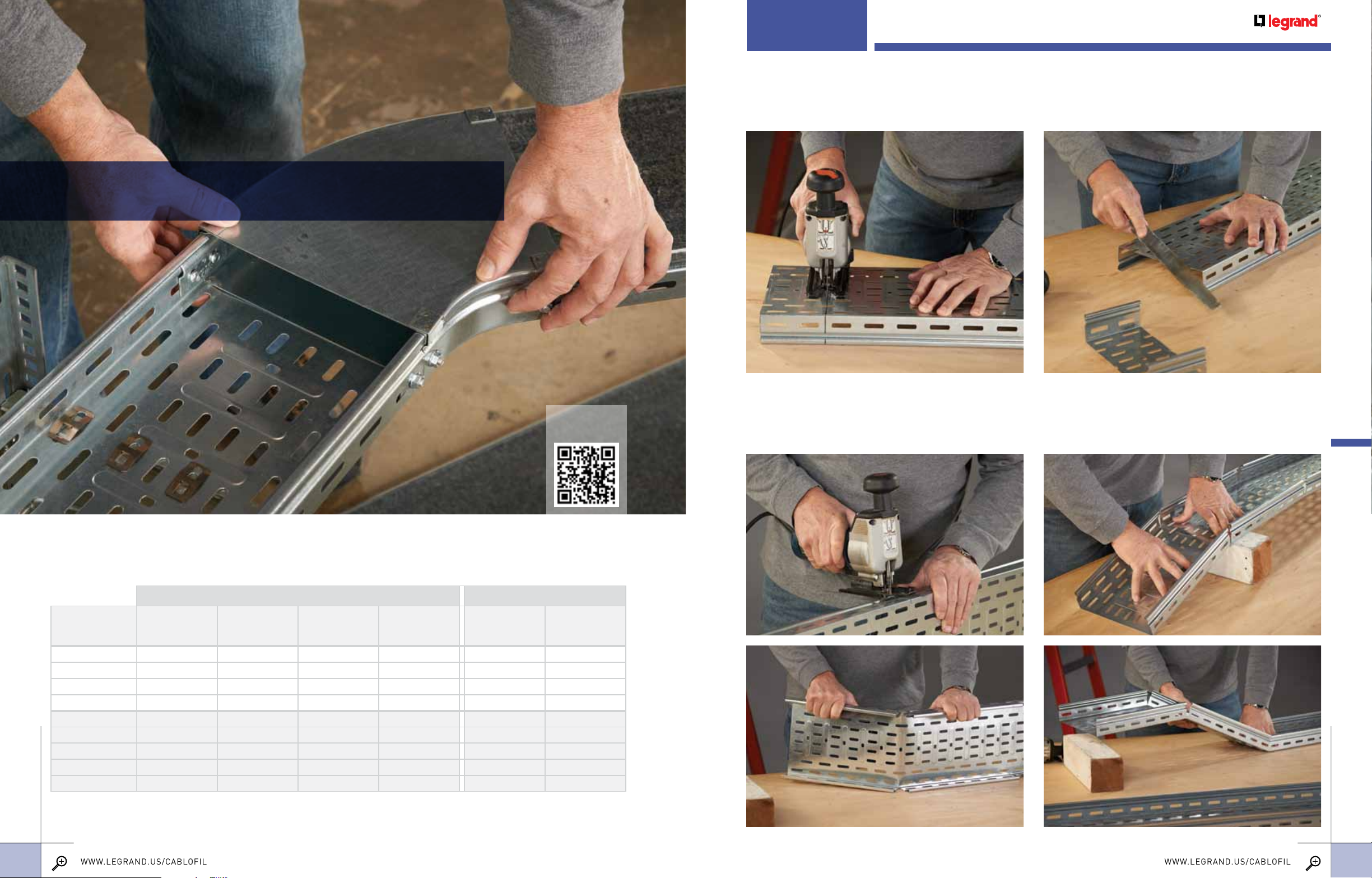
Cutting straight seCtions
V-Trough can be cut to length with a reciprocating saw fitted with a fine metal cutting blade. Mark three sides of
the tray using a square and make allowances to keep mounting hole slots in position for splicing to other straight
sections or fittings. Use a flat file to remove all rough edges. Cover sections can be modified in the same way.
Planning
Use these cable fill tables to determine the tray size(s) needed for your installation.
data cable fill table Mc Power cable fill table
MAX NUMBER OF CABLES PER CODE MAX NUMBER OF CABLES PER CODE
TRAY
VT 50/50 (2x2) 88 71 53 20 11 10
VT 50/100 (2x4) 177 142 106 41 23 21
VT 50/200 (2x8) 355 284 212 83 47 42
VT 50/300 (2x12) 532 426 318 125 71 63
VT 100/100 (4x4) 351 281 209 82 23 21
VT 100/200 (4x8) 703 563 419 165 47 42
VT 100/300 (4x12) 1055 844 629 248 71 63
VT 100/500 (4x20) 1758 1407 1049 414 119 105
INSTALLATIONS
VT 100/600 (4x24) 2110 1689 1259 497 143 126
Cat 5e 4-pr
Plenum (.17”)
Cat 5e 4-pr
Non-Plenum (.19”)
Cat 6e 4-pr
Plenum (.22”)
Cat 6a 4-pr
Plenum (.35”)
2C (12 AWG) THHN
TypeMC AlumArmor
View V-Trough
Installation Video
3C (12 AWG) THHN
TypeMC AlumArmor
Cutting straight seCtions for elevation Changes
Cut only the sides of the tray for changes in cable pathway elevations. Make a 90 degree cut in both sides of
the tray for a downward bend. For an upward bend, make a double cut to form a notch. The notch should be
sized to fit the tray angle needed. Then, using a straight edge, form the tray to the proper angles.
INSTALLATIONS
18
19
For detailed dimensions, see pages 22-23. For finish descriptions, see page 25.
Page 2
www.LEGRAND.us/cAbLofiL
www.LEGRAND.us/cAbLofiL
V-TROUGH
INSTALLATIONS
V-TROUGH
INSTALLATIONS
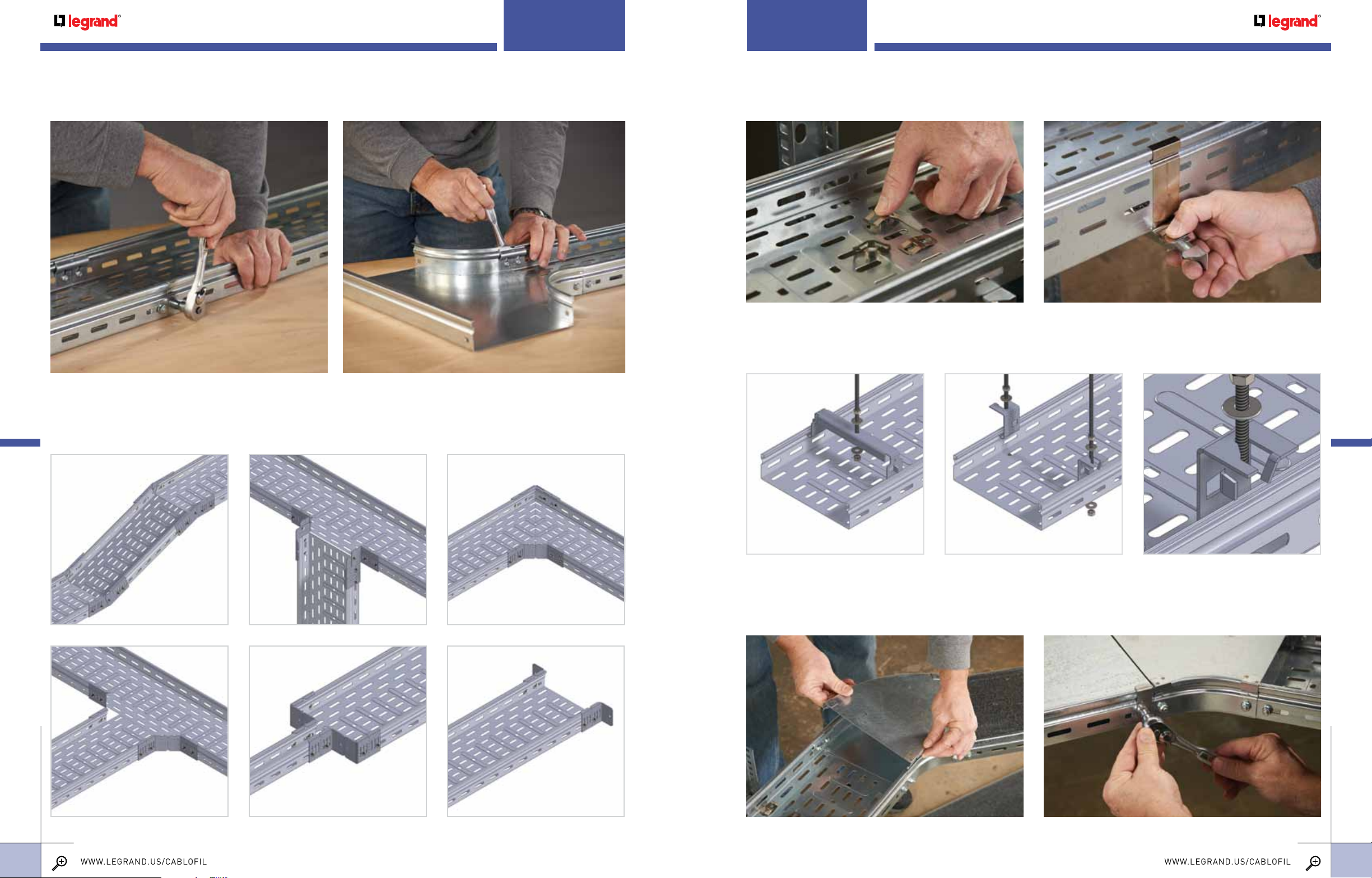
sPliCing straight seCtions and fittings
To splice straight sections of V-Trough use the FTEF. The FTEF has attachment hardware
included and should be used when splicing V-Trough straight sections or fittings.
attaChing to wall or floor suPPorts
Securing tray to supports is easy. For attachment to the FAS U or CS series support, use the FTFCL.
It simply snaps in place. Another option is the FTHDCL Tray Hold Down Clip. Both allow a cover to be used.
traPeze suPPorts
For trapeze mounting, two options are available: The FTCH Center Hanger requires only a single threaded rod. The FTAS Trapeze
Hanging Clip requires two 3/8" threaded rods, but allows cables to be side loaded. Folding tabs secure tray to supports.
sPliCing tees, reduCtions and level Changes
The FTUS is a versatile splice that can be used to construct tees, reductions and elevation changes.
Use with EZ BN 1/4 bolt/nut or BTRCC6x12.
FTCH CENTER HANGER FTAS TRAPEzE HANGING CLIP
Cover attaChment oPtions
Complete the security of your cables with covers. These cover sections can be cut to fit with a
reciprocating saw and simply snap on. For additional security, use the FTCFCL Cover Fastening
Clip. This clip can be used in conjunction with splicing hardware to keep covers secure.
INSTALLATIONS
20
INSTALLATIONS
21
For detailed dimensions, see pages 22-23. For finish descriptions, see page 25.
 Loading...