

Page 1
1/3
87045 LIMOGES Cedex
Telephone: +33 5 55 06 87 87 – Fax: +33 5 55 06 88 88
DX3 Manual Supply Invertor
Cat. Nos: 4 063 14/15/16
CONTENTS PAGE
1. Description - Use ................................ 1
2. Range ................................................. 1
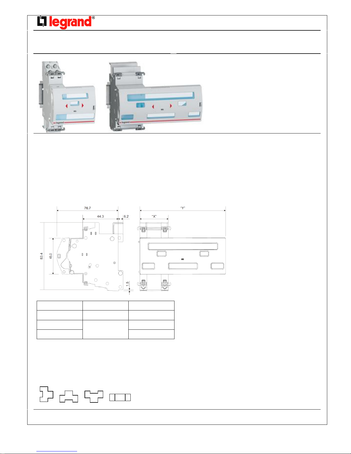
3. Overall dimensions ............................. 1
4. Preparation - Connection .................... 1
5. General Characteristics ....................... 3
6. Compliance and approvals .................. 3
1. DESCRIPTION - USE:
For a pre-defined circuit the Manual Supply Invertor (MSI), allows the end user to manually switch to another power source (ex. a generator) when
the mains supply is not available
2. RANGE
Cat. Nos:
. 4 063 14 : for devices 2 poles/2 modules.
.4 063 15 : for devices 3 poles/3 modules.
. 4 063 16 : for devices 4 poles/4 modules.
3. OVERALL DIMENSIONS:
4. PREPARATION –CONNECTION
Fixing:
. On symmetric rail EN/IEC 60715 or DIN 35 rail, by the device which is associated.
Operating positions:
. Vertical, horizontal, upside down, on the side
Cat. Nos
“X” (mm)
“Y” (mm)
4 063 14
17.8 mm
53.1 mm
4 063 15
35.6 mm
89.0 mm
4 063 16
106.8 mm
Technical data sheet: F01931EN/00
Updated: -
Created: 15/04/2014
Page 2
2/3
DX3 Manual Supply Invertor
Cat. Nos: 4 063 14/15/16
4. PREPARATION –CONNECTION
(continued)
Supply:
. No power supply.
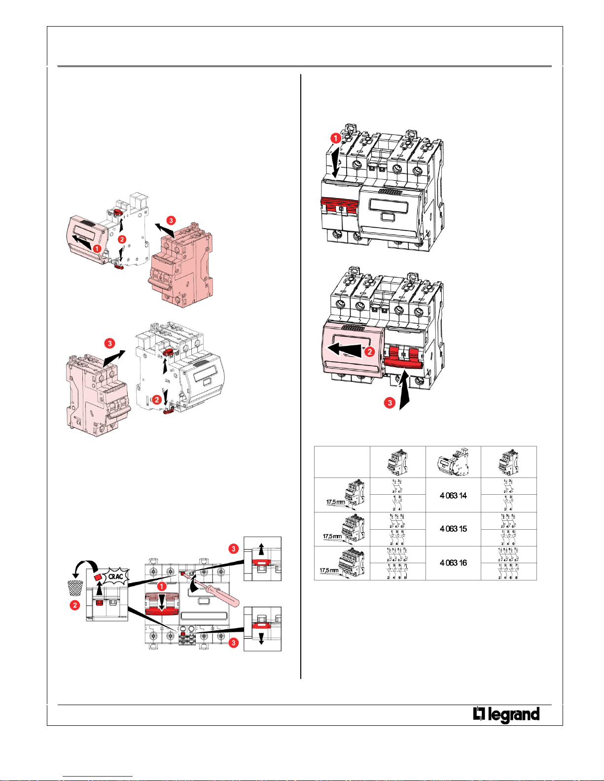
Assembling:
. Between two modular protection devices (see the association table
for the type of products to associate)
. Clipped on the associated device by mean of plastic clamps present
on each side of MSI.
. Assembling on the right side
. Assembling on the left side
Tools required:
. Fixing the MSI and protection devices: no tools.
. Fixing on the DIN rail: no tools.
. To remove the security seals: flat screwdriver 5,5 mm (6 mm
maximum).
Lockout:
. The MSI is equipped with security seals that ensure the association
between MSI and the associated device.
. By padlock on the associated device (cat. nos 4 063 13 or 227 97),
and padlock support (cat. no 4 063 03) on the device (MCB or IS)
powered-on.
4. PREPARATION –CONNECTION
(continued)
Operation:
. To perform the source inversion:
1. Lower the handle of the protection device powered-on.
2. Slide the frontal slider on the device with the handle lowered.
3. Lift the handle of the other circuit breaker to restore the supply.
Association table
. To the left and right of the Manual Supply Invertor must be installed
the same type of devices (IS-IS or MCB-MCB).
Technical data sheet: F01931EN/00
Updated: -
Created: 15/04/2014
Page 3

3/3
DX3 Manual Supply Invertor
Cat. Nos: 4 063 14/15/16
5. GENERAL CHARACTERISTICS
Front face marking:
. By permanent ink pad printing:
- Device name: MSI
- Directional arrows
- Legrand reference code and Logo
- Mark: Legrand.
Plastic materials:
. 10% Glass fiber reinforced polycarbonate
. Characteristics of this material: self extinguishing, heat and fire
resistant according to EN 60898-1, glow-wire test at 960°C.
Average weight per device:
Cat.Nos
Weight (kg)
4 063 14
0,057
4 063 15
0,089
4 063 16
0,094
Volume when packed:
Cat.Nos
Volume (m3)
4 063 14
0,49
4 063 15
1.25
4 063 16
Ambient temperature:
. operating= - 25 °C Max. = + 60 °C.
. storage= - 25 °C Max. = + 60 °C.
5. GENERAL CHARACTERISTICS
(continued)
Class protection:
. Protection index of the box against solid and liquid bodies:
IP40 (in accordance with standards IEC 529, EN 60529 and NF C 20-
010).
Sinusoidal vibration resistance in accordance with
IEC 60068-2-6:
. Axes : x, y, z.
. Frequency: 5÷100 Hz ; duration 90 minutes
. Displacement (5÷13,2 Hz) : 1mm
. Acceleration (13,2÷100 Hz) : 0,7g (g=9,81 m/s2)
Power dissipated (W) :
. 0 W.
Identification:
. MSI is equipped with several windows, so all information of the
associated device remain visible
6. COMPLIANCE AND APPROVALS
In accordance with:
. CEE guidelines : 73/23/CEE + 93/68/CEE
. Legrand devices can be used under the conditions of use as defined
by IEC /EN 60947-1
. The performance of circuit breakers can be influenced by particular
climates: hot dry, cold dry, hot humid, salt fog atmosphere
Plastic materials :
. Halogens-free plastic materials.
. Marking of parts according to ISO 11469 and ISO 1043.
Packaging:
. Design and manufacture of packaging in accordance with decree 98638 of 07.20.98 and Directive 94/62/EC
Technical data sheet: F01931EN/00
Updated: -
Created: 15/04/2014
label in the label holder
handle marking
front face marking
 Loading...