

Page 1
Wattstopper
®
Dual Technology Multi-Way Wall Switch Occupancy Sensor (V3)
No: 24582 – 08/16 rev. 1
Installation Instructions • Instructions d’Installation • Instrucciones de Instalación
Catalog Numbers • Les Numéros de Catalogue • Números de Catálogo: DW-103 and DW-203
Country of Origin: Made in China • Pays d’origine: Fabriqué en Chine • País de origen: Hecho en China
DESCRIPTION AND OPERATION
The DW Dual Technology Multi-Way Wall Switch sensors
combine advanced passive infrared (PIR) and ultrasonic
technologies into one unit. The combined technologies
help to eliminate false triggering even in difficult
applications.
Selectable operating modes allow the sensor to turn
a load ON, and hold it ON as long as either or both
technologies detect occupancy. The DW Dual Technology
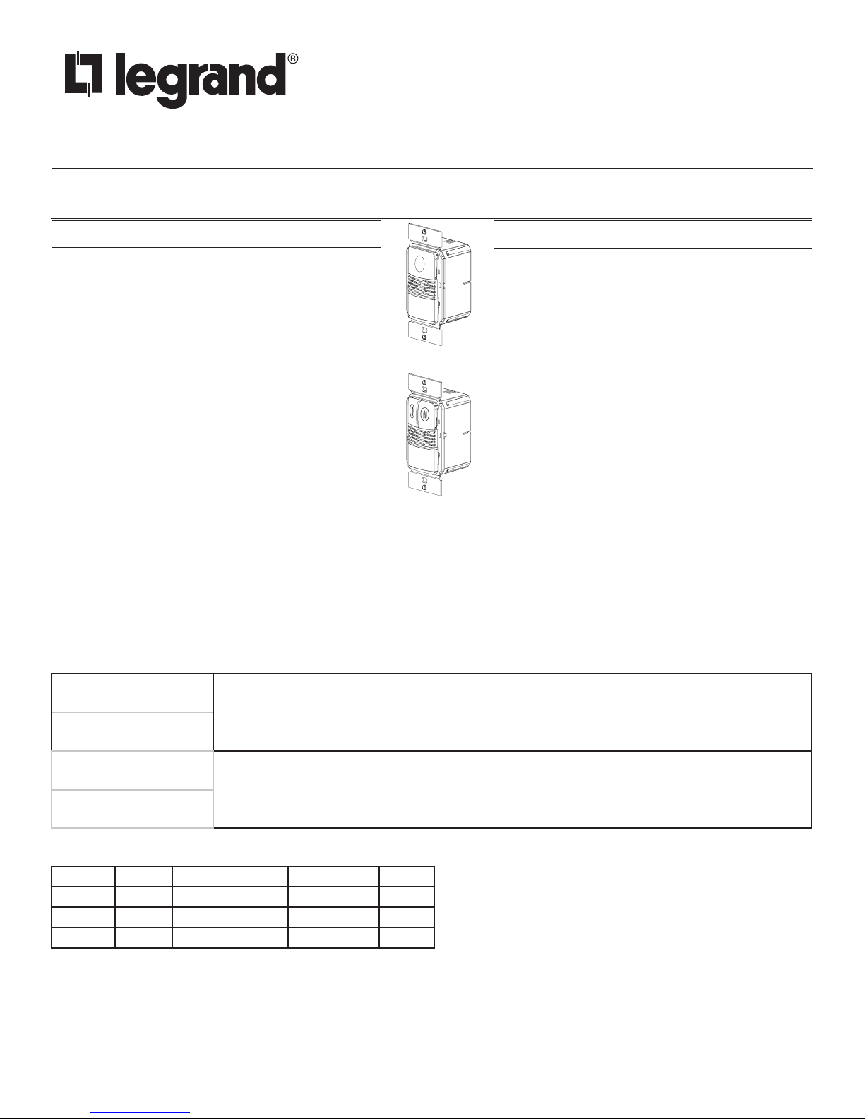
DW-103 Single Relay
Multi-Way Wall Switch Occupancy Sensor allows for up
to 4 sensors to be connected to the same circuit. The
first sensor to detect occupancy will turn ON all the lights
that are connected to the same circuit. After the room is
unoccupied, the last sensor that detected occupancy turns
OFF all the lights once the time delay has expired. The
occupant can turn OFF the load at any time by pressing
the ON/OFF button of any sensor that is connected to the
circuit. A “walk-through” mode can turn lights OFF after
only 3 minutes, if no activity is detected after 30 seconds
DW-203 Dual Relay
following an occupancy detection.
The DW-103 has one relay and one ON/OFF button. The DW-203 contains two relays and two ON/OFF buttons to allow control of one
or two loads independently. Pressing a button toggles the state of the corresponding relay.
DW sensors contain a light level sensor. If adequate daylight is present, the sensor holds the load OFF until light levels drop, even if the
area is occupied. In the DW-203, light level only affects the load on Relay 2. Users can overule this function by pressing the ON/OFF
button. See Light Level Adjustment.
Voltages ...........................................................120/277VAC, 50/60Hz
Load Limits for each relay:
@120VAC .......................... 0-800W tungsten or ballast, 1/6 HP
@277VAC ........................................................ 0-1200W ballast
Load Type Compatibility:
Incandescent, fluorescent
Horsepower Rating (each relay) ....................1/6 HP @120VAC
Time Delay Adjustment ...............................................5 to 30 minutes
Walk-Through Mode .......... 3 minutes if no activity after 30 sec.
Test Mode ................ 5 sec. for 10 min. with DIP Switch setting
PIR Adjustment ........................................... High or Low (DIP Switch)
Ultrasonic Adjustment ................. Minimum to Maximum (trimpot), Off
Frequency................................. .........................................40kHz
Light Level Adjustment ....................................................8fc to 180+fc
Alerts ......................................................................Selectable Audible
US Patents: 5640113, 6617560, 7436132, 8067906
SPECIFICATIONS
Turning ON the Load
The relays are programmed independently for either Auto ON or Manual ON. In either mode, the load can be turned ON or OFF using
the ON/OFF button. In either mode, the load can be turned ON or OFF using the ON/OFF button.
Auto ON
(DIP# 8 OFF for Relay 1)
(DIP #9** OFF for Relay 2)
Manual ON
(DIP #8 ON for Relay 1)
(DIP #9** ON for Relay 2)
With an ON Mode DIP Switch in the OFF position, the load turns ON and OFF automatically based on
occupancy. If the load is turned OFF manually, Presentation Mode operation applies. This prevents the
load from turning ON automatically after it was deliberately turned OFF. Pressing the button to turn lights
ON returns the sensor to Auto ON mode.
With an ON Mode DIP Switch in the ON position, the occupant must press the ON/OFF button to turn
ON the load. The sensor keeps the load ON until no motion is detected for the selected time delay.
There is a 30 second re-retrigger delay. If occupancy re-triggers during the delay (see Trigger Mode), the
sensor turns the load back ON. After the re-trigger delay elapses the ON/OFF button must be pressed to
turn ON the load.
** DW-103: DIP Switch 9 is not used. DW-203: DIP Switch 9 default is ON to comply with CA Energy Commission Title 24 bi-level
switching requirements.
Sensor Relay Default ON Mode DIP Switch # Setting
DW-103 1 Manual ON 8 ON
DW-203 1 Auto ON 8 OFF
2 Manual ON 9 ON
Presentation Mode
This is a feature of the Auto ON mode. When both relays are manually turned OFF the DW holds the lights OFF until no motion has
been detected for the duration of the Time Delay. With subsequent occupancy, the DW turns the load ON. If both relays are ON and one
relay is manually turned OFF this relay remains OFF until both the Time Delay and the retrigger delay expire for the relay that is ON.
After that time the ON Mode control settings again apply.
Page 2
NOTE: Shaded cells below indicate default operation and switch setting.
Time Delays
The DW sensor holds the load ON until no motion is detected for the selected time delay. Select the time delay using DIP Switch
settings. In the DW-203, both relays use the same delay.
Test/20 min
(DIP# 1 & 2 OFF)
A Test Mode with a short time delay of five seconds is set when DIP Switches 1 & 2 are OFF. It cancels
automatically after ten minutes, or when you set a fixed time delay. When the Test Mode times out, the
sensor will assume a 20 minute time delay. To restart Test Mode, change the time delay setting to any fixed
amount and then return it to the Test setting.
Time Delay / 15 min.
Time delays of 5, 15 (default), or 30 minutes are available. See DIP SWITCH SETTINGS for information.
(DIP# 1 ON & #2 OFF)
Walk-Through
The Walk-Through mode shortens the time delay to reduce the amount of time the load is ON after a brief moment of occupancy, such
as returning to an office to pick up a forgotten item, then immediately exiting.
Walk-Through Mode
(DIP# 3 ON)
No Walk-Through
The DW sensor turns the load OFF three minutes after the area is initially occupied, if no motion is detected
after the first 30 seconds. If motion continues beyond the first 30 seconds, the set time delay applies.
Walk-Through mode disabled.
(DIP# 3 OFF)
PIR Sensitivity Adjustment
The DW sensor constantly monitors the controlled environment and automatically adjusts the PIR to avoid common ambient conditions
that can cause false detections, while providing maximum coverage.
High
Default setting. Suitable for most applications.
(DIP #4 OFF)
Low, 50%
(DIP #4 ON)
Reduces sensitivity by approximately 50%. Useful in cases where the PIR is detecting movement
outside of the desired area (also consider masking the lens) and where heat sources cause unnecessary
activation.
Alerts
The DW can provide audible alerts as a warning before the load turns OFF.
Audible Alerts
(DIP #7 ON)
No Audible Alerts
Unit will beep at one minute, at 30 seconds, and at 10 seconds before turning OFF load. When
Walk-Through is active, the unit beeps three times at 10 seconds before the load goes OFF.
No audible warnings provided.
(DIP #7 OFF)
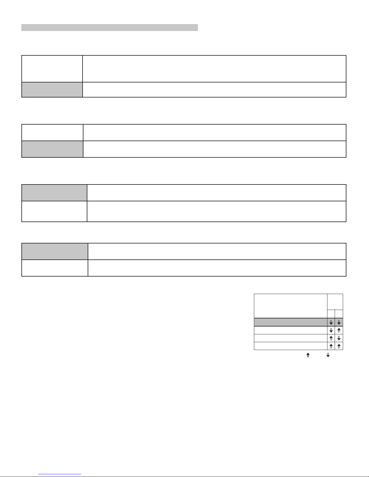
Trigger Mode
The DW sensor has 4 occupancy trigger options, set with DIP Switches 5 and 6. Determine the
appropriate option using the Trigger Mode matrix.
In the Trigger Mode DIP Switch setting table, in order to deem the area occupied:
• Both requires motion detection by the PIR and the Ultrasonic.
• Either requires motion detection by only one technology.
• PIR requires motion detection by the PIR.
Initial Occupancy: The method that activates a change from “Standby” (area unoccupied and
load OFF) to “Occupied” (area occupied and load may turn ON).
Maintain Occupancy: The method indicating that the area is still occupied and the lights should
remain ON.
Trigger
Mode
Standard
Option A
Option B
Option C
Initial
Maintain
Occupancy
Occupancy
Both EitherEither
Either EitherPIR
PIRPIR PIR
Both Both Both
=ON =OFF
Re-trigger: In Manual ON mode, after the load automatically turns OFF, detection by the
selected technology within 30 seconds automatically turns the lights back ON. In Auto ON mode, after the load turns OFF automatically,
detection by the selected technology turns the lights back ON.
DIP
Switch
Re-trigger
56
2
Page 3

COVERAGE PATTERNS
(10.6m)
(6.1m)
4’
(1.2m)
(6.1m)
35’
)
Strip Gauge
12.7mm
15’
(4.5m)
Top View
7.5’
(2.2m)
7.5’
(2.2m)
(3.0m)
Major motion
Minor motion
Ultrasonic
Coverage
20’
15’
(4.5m)
10'
20’
(10.6m
Coverage testing has been performed according to the NEMA WD 7 guideline. For best
performance, use in spaces not larger than 18' x 15'.
PIR Sensor
The sensor has a two-tiered, multi-cell viewing Fresnel lens with 180 degree field of view. The red
Major motion
Minor motion
PIR
Coverage
35’
LED on the sensor flashes when the PIR detects motion.
Masking the Lens
Opaque adhesive tape is supplied so that sections of the PIR sensor’s view can be masked. This
allows you to eliminate coverage in unwanted areas. Since masking removes bands of coverage,
remember to take this into account when troubleshooting coverage problems.
20’
(6.1m)
Ultrasonic Sensor
The sensor has two ultrasonic transceivers operating at 40kHz. Detection sensitivity can be
adjusted using the trimpot under the ON/OFF buttons.
Service Mode
The Service Mode allows the DW to operate as a toggle switch. Service Mode turns OFF all the
sensor features, and only allows load control through the button(s). While in Service mode, the
time delay, detection, and light level settings are ignored and Ultrasonic transmisions are turned OFF. To activate the Service Mode, turn
the Ultrasonic trimpot fully clockwise to MIN. The Red LED turns ON and stays on until the trimpot is returned to a normal setting.
Side View
0
INSTALLATION
1. Make sure that the power has been turned OFF at the circuit breaker.
2. Connect wires to the DW flying leads as shown in the wiring diagram
that is appropriate to the DW model and electrical supply. The ground
wire (green) must be fastened to ground for the sensor to work
properly.
3. Attach the sensor to the wall box by inserting screws into the two wide holes on the top and bottom of the
attached metal bracket. Match them up with the holes in the wall box and tighten.
4. Turn the circuit breaker ON. Wait one minute, then push the Auto ON/OFF switch for each load and the lights
will turn ON. There is a delay due to initial power-up of the sensor that only occurs during installation.
5. Test and adjust the sensor if necessary.
6. Attach the cover plate.
Load
White (Neutral)
Black (Line)
DW-103
Remote
1
Black (Line)
Ground
DW-103
Main
Junction BoxJunction Box
White (Neutral)
Red (Load 1)
Yellow (Traveler)
White (Neutral)
Black (Line)
DW-203
Remote
WARNING: TURN THE POWER OFF AT THE
CIRCUIT BREAKER BEFORE WIRING.
#12 – #14 AWG
Cu Wire Only
Load 2
2
Load 1
1
Junction Box
Junction Box
White (Neutral)
Black (Line)
Blue (Line)
Red (Load 1)
Brown (Load 2)
Yellow (Traveler)
Ground
1/2"
DW-203
Main
DW-103 Wiring
Load 2
2
White (Neutral)
Black (Line 2)
Black (Line 1)
DW-203
Remote
White
Blue
Black
Red
Brown
Yellow
DW-203 Dual Circuit Wiring
Junction
Box
Load 1
1
Junction
Box
White (Neutral)
Blue (Line 2)
Black (Line 1)
Red (Load 1)
Brown (Load 2)
Yellow (Traveler)
GroundGround
DW-203
Main
DW-203 Bi-Level Wiring
Important:
Wire the remote unit to the same branch circuit as the main
unit controlling the load. If relay 2 of the main unit cannot be
controlled from the remote unit, check wiring to be sure both
units are on the same branch circuit.
3
Page 4

DIP SWITCH SETTINGS
7
=ON =OFF
On Mode
DW-200 series
ON/OFF Buttons
Relay 1
Relay 2
Tabs
Button
Hinges
DW-203 shown.
DW-103 has a single
button and the
Ultrasonic
Sensitivity
Adjustment
Trimpot
'(/$<
:$/.
75,**(5
3,5
$/(576
5/<0$1
5/<0$1
DIP Switches
Ultrasonic
Cones
Detection LEDs
Red = PIR
Green =
Ultrasonic
PIR Lens
Time Delay
Test
5 minutes
15 minutes
30 minutes
Walk-Through
Enabled
Disabled
PIR Sensitivty
Low, 50%
High
12
3
4
Time
Delay
ON
123456 78
Walk-Through
PIR Sensitivity
Trigger
Mode
Standard
Option A
Option B
Option C
Trigger
Mode
Audible Alerts
Initial
Maintain
Re-trigger
Occupancy
Occupancy
Both Either(5)Either
Either Either(5)PIR
PIRPIR PIR
Both Both Both
Relay 1
Relay 2
9
duration)
(seconds
56
Audible Alert
Enabled
Disabled
Relay 1
ON Mode
Manual On
Auto On
DW-203 only:
Relay 2
On Mode
Manual On
Auto On
Factory Settings:
All models
1
DW-100 series
2
8
1
2
9
Ultrasonic sensitivity
adjustment trimpot
is in a slightly
different position.
ADJUSTMENTS
Sensor Adjustment
Remove the wall plate. Remove the button cap by firmly squeezing together the top sides of the button assembly. Gently pull it away
from the unit.
When the adjustments are completed, replace the button cap by inserting its hinges into the tabs on the main unit and then squeeze the
top of the button while pressing it into the unit. Reinstall the cover plate.
Light Level Adjustment
The light level can be set with loads ON or OFF. The light level feature operates as a Hold OFF function, meaning that once the light
level in a room reaches a set point the lights will not turn ON until the light level drops below the set point. In order to achieve the
maximum energy savings the light level feature offers, pick a time during the day when there is enough ambient light in the room to
perform the necessary tasks without the aid of artificial light. In order to set this as the threshold level of brightness so that the artificial
lights remain OFF, perform the following steps:
1. Make sure the room is lit appropriately.
2. Put the sensor into TEST mode. You have 5 minutes to complete the procedure.
3. Press and hold the ON/OFF button (Relay 1 button on the DW-203) for 3 seconds, until you hear a beep.
4. Step away from the sensor. After 25 seconds a beep sounds, indicating that the threshold level is set. This threshold is retained,
even if power is lost, until it is re-set or disabled. In the DW-203, light level control only affects Relay 2.
To disable light level control, press and hold the ON/OFF button (Relay 1) button for 7 seconds, until a double beep tone sounds.
Reset to Default
Use the DIP Switch Settings tables to return features to factory settings. To reset the DW press and hold the ON/OFF button (Relay 1)
for 10 seconds, until a triple beep sounds. This resets the sensor and disables light level control (the brightest ambient light will not hold
the light OFF).
Service Mode
To enter service mode set the ultrasonic trimpot to MIN (Fully counter-clockwise).
4
Page 5

TROUBLESHOOTING
Lights do not turn ON with motion (LED does ash).
1. Press and release each button to make sure that the correct lights come ON for each relay. If the lights do NOT turn ON, check
wire connections, especially the Load connection. If the lights turn ON, verify that the correct ON Mode is selected in DIP Switches
8 and 9.
2. Check to see if light level control is enabled: cover the sensor lens with your hand. If the lights come ON, adjust the light level
setting.
3. If lights still do not turn ON, call 800.879.8585 for technical support.
Lights do not turn ON with motion (LED does not ash).
1. Press and release each button to make sure that the correct lights come ON for each relay. If the lights turn ON, verify that PIR
and Ultrasonic sensitivity are set to High.
2. Check the wire connections.
• Verify the ground connection.
• Make sure line and load are not reversed.
• Confirm that connections are tightly secured.
3. If lights still do not turn ON, call 800.879.8585 for technical support.
Lights do not turn OFF.
1. There can be up to a 30 minute time delay after the last motion is detected. To verify proper operation, set DIP Switch 1 to
ON, then reset Switches 1 and 2 to OFF to start Test Mode. Move out of view of the sensor. The lights should turn OFF in
approximately 5 seconds.
2. Verify that the sensor is mounted at least six feet (2 meters) away from any heating/ventilating/air conditioning device that may
cause false detection. Verify that there is no significant heat source (such as a high wattage light bulb) mounted near the sensor.
3. Verify that the trimpot is not pointing at “override” (red LED ON). If so, rotate the trimpot to it’s middle setting (pointing up). The
override setting allows users to operate the sensor as a service switch in the unlikely event of a failure.
4. If the lights still do not turn OFF, call 800.879.8585 for technical support.
Sensing motion outside desired areas.
1. Select PIR Sensitivity – Low (DIP Switch 4 = ON) if necessary.
2. Mask the PIR sensor’s lens to eliminate unwanted coverage area.
3. Adjust the Ultrasonic Sensitivity. Rotate the trimpot counterclockwise to reduce sensitivity.
Red LED is lit all the time and the sensor features don’t work.
1. Check the Ultrasonic trimpot. If it is set at fully clockwise (MIN) the unit is in Service Mode. Set the trimpot to a mid-range position.
2. If re-setting the trimpot does not clear the LED, call technical support.
COVER PLATES
Wattstopper DW series wall switches fit behind industry standard decorator-style switch cover plates. Cover plates are not included.
Units come in the following colors, which are indicated by the final suffix of the catalog number (shown here in parentheses):
White (-W), Light Almond (-LA), Ivory (-I), Grey (-G), Black (-B).
5
Page 6

WARRANTY INFORMATION INFORMATIONS RELATIVES À LA GARANTIE INFORMACIÓN DE LA GARANTÍA
Wattstopper warranties its products to be free
of defects in materials and workmanship for a
period of five (5) years. There are no obligations
or liabilities on the part of Wattstopper for
consequential damages arising out of, or in
connection with, the use or performance of this
product or other indirect damages with respect
to loss of property, revenue or profit, or cost of
removal, installation or reinstallation.
No. 24582 – 08/16 rev. 1
© Copyright 2016 Legrand All Rights Reserved.
© Copyright 2016 Tous droits réservés Legrand.
© Copyright 2016 Legrand Todos los derechos reservados.
Wattstopper garantit que ses produits sont
exempts de défauts de matériaux et de fabrication
pour une période de cinq (5) ans. Wattstopper
ne peut être tenu responsable de tout dommage
consécutif causé par ou lié à l’utilisation ou
à la performance de ce produit ou tout autre
dommage indirect lié à la perte de propriété, de
revenus, ou de profits, ou aux coûts d’enlèvement,
d’installation ou de réinstallation.
Wattstopper garantiza que sus productos
están libres de defectos en materiales y mano
de obra por un período de cinco (5) años. No
existen obligaciones ni responsabilidades por
parte de Wattstopper por daños consecuentes
que se deriven o estén relacionados con el
uso o el rendimiento de este producto u otros
daños indirectos con respecto a la pérdida
de propiedad, renta o ganancias, o al costo
de extracción, instalación o reinstalación.
800.879.8585
www.legrand.us/wattstopper
 Loading...